

Summit Systems SFC-500 SERIES Installation Instructions Manual

SFC-500 SERIES
FIRE ALARM PANEL
INSTALLATION
INSTRUCTIONS
LT-959SUM Rev 1

Canada
25 Interchange Way
Vaughan, ON L4K 5W3
U.S.A.
4575 Witmer Industrial Estates
,
w
Niagara Falls
Ne
York 14305
Phone: 1-866-SUMM
Fax: 1-888-660-4113
www.summit-st.net
-0 (1-866-786-6480)
IT

SFC-500 Series Installation and Operation Manual
Table of Contents
List of Figures ..................................... .......................................... ........................................... ii
FCC Notice.............................. ... .... .......................................... ............................................. ... . 1
Introduction.............................................................................................................................. 2
Conventions ............................................................................................................................ 3
System Components .............................................................................................................. 4
Panel Models ........................................................................................................................ 4
Output Class A converter: four circuits ................................................................................. 4
Polarity reversal/city tie ......................................................................................................... 4
Remote Annunciator ............................................................................................................. 5
Smart Relay Module ............................................................................................................. 5
SRAM-216 Remote Annunciator........................................................................................... 5
Panel Components and System Accessories ....................................................................... 6
Analog/Addressable Devices ................................................................................................ 7
Mechanical Installation ........................................................................................................... 8
Installing Adder Modules ........................................................................................................ 10
Circuits and Devices.................................. ... ... .......................................... .............................. 14
Field Wiring .............................................................................................................................. 16
Main Fire Alarm Board Field Wiring ..................................................................................... 16
Loop Isolators ....................................................................................................................... 16
Loop Operation ..................................................................................................................... 17
Indicating (Powered Output) Circuits .................................................................................... 18
Indicating Circuit Wiring ....................................................................................................... 18
Dialer Wiring ......................................................................................................................... 20
Polarity Reversal and City Tie Module (SPR-200) Wiring .................................................... 21
Auxiliary Power Supplies ...................................................................................................... 22
Power Supply Connections................................................................................................... 23
System Checkout .................................................................................................................... 24
Troubleshooting ................................. .......................................... ........................................... 24
Indicators, Controls and Operations ..................................................................................... 25
Remote Annunciators Operation............................................................................................ 34
Dialer Operation ....................................................................................................................... 35
Appendix A: Compatible Receivers ......................... ... ... ... .... ... .......................................... .... 35
Appendix B: Reporting........................................................................................................... 36
Appendix C: Specifications.................................................................................................... 38
Appendix D: Power Supply and Battery Calculations......................................................... 39
Warranty & Warning Information............................. ... ... ... .......................................... ........... 41
i

SFC-500 Series Installation and Operation Manual
List of Figures
Figure 1: Wallbox Dimensions / Mounting the SFC-500 - Surface .......................................... 8
Figure 2: Mounting the SFC-500 - Flush ................................................................................ 9
Figure 3: Flush Trim Detail ...................................................................................................... 9
Figure 4: Installation of Adder Modules .................................................................................. 10
Figure 5: Main Fire Alarm Board Cable Connectors and Jumper Locations ........................... 11
Figure 6: SOCA-204 Output Class A Converter Adder Modules............................................. 12
Figure 7: Polarity Reversal and City Tie Module .................................................................... 13
Figure 8: Addressable Loop Wiring - Class B or Style 4 ......................................................... 16
Figure 9: Addressable Loop Wiring -Class A or Style 6 .......................................................... 17
Figure 10: Indicating Circuit – Class B or Style Y Wiring .......................................................... 19
Figure 11: Indicating Circuit –Class A or Style Z Wiring............................................................ 19
Figure 12: Dialer Wiring ............................................................................................................ 20
Figure 13: Polarity Reversal and City Tie Module Terminal Connection .................................. 21
Figure 14: Supervision Of Auxiliary Supplies ............................................................................ 22
Figure 15: Main Power Supply Connections ............................................................................. 23
Figure 16: LCD Display, LED indicators and control buttons ................................................... 25
Figure 17: Evacuation Codes .................................................................................................... 31
ii

SFC-500 Series Installation and Operation Manual
FCC Notice
Notice for all SFC-500 Series Built-in UDACTs Sold in the U.S.A.
Note: The Ringer Equivalence Number (REN) assigned to each terminal device provides an indication of the maximum number
of terminals allowed to be connected to a telephone interface. The termination on an interface may consist of any
combination of devices subject only to the requirement that the sum of the Ringer Equivalence Numbers of all the devices
does not exceed 5.
The REN for this product is part of the product identifier that has the format US:1M8AL02BFX350. The 02B represents the
REN without a decimal point (e.g., 02B is a REN of 0.2B). For earlier products, th
Summit's SFC-500 SERIES BUILT-IN UDACT Digital Communicator described in this manual is listed by Underwriters Laboratories Inc.
(ULI) for use in slave application in conjunction with a Listed Fire Alarm Control Panel under Standard 864 (Control Units for Fire Protective
Signalling Systems). These Communicators comply with the National Fire Protection Association (NFPA) performance requirements for
UDACTs and should be installed in accordance with NFPA 72 Chapter 4 (Supervising Station Fire Alarm System). These Communicators
should be installed in accordance with this manual; the National Electrical Code (NFPA 70); and/or the local Authority Having Jurisdiction
(AHJ).
FCC Notice
This equipment complies with Part 68 of the FCC rules and the requirements adopted by the ACTA. On the telco transformer of this
equipment is a label that contains, among other information, a product identifier in the format US:1M8AL02BFX350. If requested, this
number must be provided to the telephone company. This equipment is capable of seizing the line. This capability is provided in the
hardware.
Type of Service: The Communicator is designed to be used on standard device telephone lines. It connects to the telephone line by
means of a standard jack called the USOC RJ-11C (or USOC FJ45S). Connection to telephone company provided coin service (central
office implemented systems) is prohibited. Connection to party lines service is subject to state tariffs.
Telephone Company Procedures: The goal of the telephone company is to provide you with the best service it can. In order to do this, it
may occasionally be necessary for them to make changes in their equipment, operations or procedures. If these changes might affect your
service or the operation of your equipment, the telephone company will give you notice, in writing, to allow you to make any changes
necessary to maintain uninterrupted service.
In certain circumstances, it may be necessary for the telephone company to request information from you concerning the equipment which
you have connected to your telephone line. Upon request of the telephone company, provide the FCC registration number and the ringer
equivalence number (REN); both of these items are listed on the equipment label. The sum of all of the REN’s on your telephone lines
should be less than five in order to assure proper service from the telephone company. In some cases, a sum of five may not be usable on
a given line.
If Problems Arise: If any of your telephone equipment is not operating properly, you should immediately remove it from your telephone line,
as it may cause harm to the telephone network. If the telephone company notes a problem, they may temporarily discontinue service. When
practical, they will notify you in advance of this disconnection. If advance notice is not feasible, you will be notified as soon as possible.
When you are notified, you will be given the opportunity to correct the problem and informed of your right to file a complaint with the FCC.
Contact your telephone company if you have any questions about your phone line. In the event repairs are ever needed on the
Communicator, they should be performed by Summit Systems Technologies or an authorized representative of Summit Systems
Technologies For information contact Summit Systems Technologies at the address and phone numbers shown on the back page of this
document.
e REN is separately shown on the label.
1

Introduction
Introduction
Summit’s SFC-500 Series Analog/Addressable Fire Alarm Control Panel provides a loop for 60 or 126 addressable
input and output devices, four supervised Class B or A (Style Y or Z) indicating circuits, a full range of auxiliary
power supplies, and extensive common control features via its integrated LCD display and push button console.
Many of its features are fully configurable utilizing the built-in configuration capability via the front panel display and
switches. The panel is available with an integrated dialer/modem. Optional modules include Polarity Reversal and
City Tie, and Class A Converter for indicating circuits. Semi-flush or surface mountable enclosures can be used for
retrofits and on new installations. This manual covers the following panels:
SFC-500-60-DR One Loop (60 devices) Panel, c/w dialer, red door
SFC-500-126-DR One Loop (126 devices) Panel, c/w dialer, red door
Note: Installation of the SFC-500 Series Fire Alarm Control panel should be in accordance with National
Electrical Code NFPA 70 and NFPA 72. Final acceptance subject to the Local Authority Having
Jurisdiction (AHJ).
Features
• The SFC-500 panels support a loop of 60 or 126 addressable devices, including thermal, ion, photo detectors,
and contact input and output devices. Drift compensation and Auto Test features are provided for analog
devices.
• Four Power Limited Class B (Style Y) indicating circuits. Each indicating circuit may be configured as Class A
(Style Z) using an output Class A converter adder module. Each indicating circuit may be configured as
silenceable signal, non-silenceable signal, silenceable strobes, non-silenceable strobes, or relay output. The
audible signal may be Steady, Temporal Code, California Code, or March Time. The system provides the
necessary protocols to sync strobes from major manufacturers.
• Configurable Signal Silence Inhibit, Auto Signal Silence, and One-Man Walk Test.
• Subsequent Alarm, Supervisory, and Trouble operation.
• provides a regulated, supervised 21.1VDC auxiliary power supply @ 500mA max.; unfiltered, unsupervised 24V
FWR power supply @ 1.7 A max and a resettable auxiliary power supply @ 300mA max.
• Relay Contacts for Common Alarm, Common Supervisory and Common Trouble all non-disconnectable and
Auxiliary Alarm Relay (disconnectable).
• Output for remote trouble indicator and Buzzer.
• RS-485 Interface for SRAM-200LCD Annunciators, SRA-300 Series Remote Annunciators, SRAM-216 and
SRAM-208 Remote Annunciators and SSR-212 Smart Relay Modules (max total of 7 remote annunciators).
• Optional Module for City Tie and Polarity Reversal Signaling.
• Extensive transient protection
• Built-in UDACT (Digital Alarm Communicator Transmitter).
• Extensive and easy configuration of the panel via the integrated LCD display and keypad or laptop computer.
• Remote dial up (with built-in UDACT) for event log checking and/or configuration changing
2

SFC-500 Series Installation and Operation Manual
Conventions
Circuits
Refers to a physical electrical interface for the analog loop, indicating signals or relays, and common alarm,
supervisory, and trouble relay outputs.
Zone/Group
Is a logical concept for a Fire Alarm Protected Area, and will consist of at least one Circuit. Groups are used to
facilitate bypassing of inputs and outputs.
Display Points
The SFC-500 provides an LCD display to annunciate the status of the system and connected devices.
Wiring Styles
The analog loop can be connected in Class B (Style Y) or Class A (Style D) configurations. Changing the indicating
circuits to Class A requires an SOCA-204 adder board which will convert four indicating zones from Class B (Style
Y) circuits to Class A (Style Z). This is done without reducing the number of circuits.
Note: The Model SFC-500-60DR panels DO NOT recognize any devices with addresses higher than 60.
3

System Components
- SIG1 OUT+- SIG2 OUT+
- SIG1 RET+- SIG 2 RET+
BLK RED
BLK RED
- SIG3 OUT+- SIG4 OUT+
- SIG3 RET+- SIG 4 RET+
BLK RED
BLK RED
POLARITY
REVERSAL
ALARM
POLARITY
REVERSAL
SUPV
CITY
TIE
+ | - + | - + | -
JW4
System Components
Panel Models
SFC-500 SERIES
Addressable Fire Alarm Control Panel
SYSTEM NORMAL
MAY 21, 2006 02:41PM
AC ON
1 2
X
ABC3DEF
COMMON ALARM
5
4
GHI
7 8
PRS
* 0QZ#
M
JKL6MNO
?
TUV9WXY
SIGNAL
SILENCE
BUZZER
SILENCE
LAMP
TEST
SPARE
COMMON SUPV
COMMON
TROUBLE
CPU FAULT
GROUND
FAULT
SYSTEM
RESET
FIRE
DRILL
ALARM
ACKNOWLEDGE
GENERAL
ALARM
Model Description
Multi-zone fire alarm control panel with 2 x 20 L CD
display, one (Style Y or Style D) analog loop (60 or
126 devices), four Power Limited Class B (Style Y)
indicating circuits (max 1.7 Amps each - 5 Amps
total), and dedicated common alarm, supervisory,
trouble, and auxiliary alarm relays. Both these
models have a two line UDACT Digital
Communicator and modem included. An optional
SFC-500-60-DR,
SFC-500-126-DR
SOCA-204 Class A converter module may be used
to convert the indicating circuits to Class A (S tyle Z).
Additional outputs include connections for a SRTI200 remote trouble indicator, SPR-200 Reverse
Polarity Module, an RS-485 bus for connection of
up to seven SRAM-200LCD, SSR-212, SRA-300
Series and SRAM-216/208 annunciators. Auxiliary
power is available in the form of 24V FWR unfiltered
and unsupervised, 24VDC filtered and regulated,
and resettable auxiliary power supply . The panels
are available with a red door.
Output Class A converter: four circuits
Polarity reversal/city tie
4
Model Description
SOCA-204
Output Class A converter module (four
circuits)
Model Description
SPR-200
Polarity Reversal and/or City
Tie Module
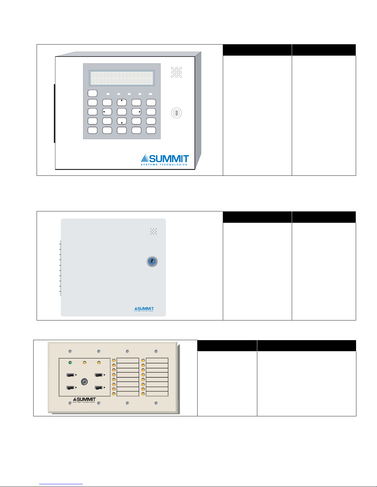
Remote Annunciator
SFC-200 SERIES
Remote Annunciat or
SYSTEM
RESET
SIGNAL
SILENCE
FIR E
DRILL
BUZZER
SILENCE
LAMP
TEST
1
4
7
*
2
5
8
0
3
6
9
#
ENTER
MEN U
CANCEL
INFO
ABC DEF
GHI JKL MNO
PRS
TUV
WXY
QZ
A.C. ON ALARM SUPV TRBL CPU FAIL
SYSTEM NORMAL
18:01 MON 2003-04-05
A.C.ONCOMMON
TROUBLE
SIGNAL
SILENCED
SIGNAL
SILENCE
SYSTEM
RESET
LAMP
TEST
BUZZER
SILENCE
SRAM-216
SFC-500 Series Installation and Operation Manual
Model Description
Remote Annunciator
SRAM-200LCDR
Module, LCD
display, red painted
box
Smart Relay Module
SFC-200 SERIES Remote Relay
SRAM-216 Remote Annunciator
Model Description
Smart Relay Module
SSR-212R
(12 relays) with red
enclosure
Model Description
SRAM-216 16 Zone remote annunciator
5

System Components
Panel Components and System Accessories
MODEL NO. DESCRIPTIONS
SRAM-208 / R 8 LED Remote Annunciator
SRAM-316 16 LED Remote Annunciator chassis
SRAM-332 / TZ
SGD-32 Graphic Annunciator
SGD-048 Graphic Annunciator Adder Driver Board
SRTI-200 Remote Trouble Indicator, Buzzer and LED
SFC-200TRB Trim Ring For Enclosure (Black)
SBB-301 / R Enclosure for one annunciator, white. R version is red.
MP-300 End-of-line resistor plate, 3.9K ohm
BC-160 External Battery Cabinet
Remote Annunciator with 32 bi-colored (red and yellow) LEDs. TZ version has 32 yellow
LEDs for trouble indication.
6

SFC-500 Series Installation and Operation Manual
Analog/Addressable Devices
DESCRIPTION Summit Model
Ionization Smoke Detector (UL Listed) SII-200
Photoelectric Smoke Detector SIP-200
* Multi-sensor (photoelectric with supplemental rate-of-rise heat sensor)
Heat Detector SIH-200
SIM-200
BASES
4 inch Standard Base SIB-4
6 inch E-Z Fit Base SIB-6
6 inch Base with Relay SIB-6R
6 inch Base with Sounder SIB-6S
6 inch Base with Temporal Tone Sounder SIB-6TH
ANCILLARY MODULES
Priority Monitor Module SIM-100P
Mini Priority Monitor Module SIM-101P
Single Relay Output Module (1 Form C Contacts, 2 Gang Mount) 55000-820
Supervised Control Module SIM-100S
SIM-100X (Kit)
Isolator c/w Mounting Base
100XH (Isolator)
100XB (Base)
ADDRESSABLE DUCT DETECTORS
Ionization Duct Smoke Detector (UL Listed) SIDH-200I
Photoelectric Duct Smoke Detector (UL Listed) SIDH-200P
Ionization Duct Smoke Detector with relay (UL Listed) SIDH-200IR
Photoelectric Duct Smoke Detector with relay (UL Listed) SIDH-200PR
ADDRESSABLE PULL STATIONS
Addressable Single Stage Single Action Pull Station SPS-201ID
Addressable Single Stage Dual Action Pull Station SPS-202ID
* Unit employs an integral heat sensor; however it must not be used as a regular heat detector. Refer to the
product data sheet for detailed functionality, operation and application.
Manual configuration for the SIM-200 is NOT PERMITTED. This device must be configured via the AUTO
CONFIG.
7
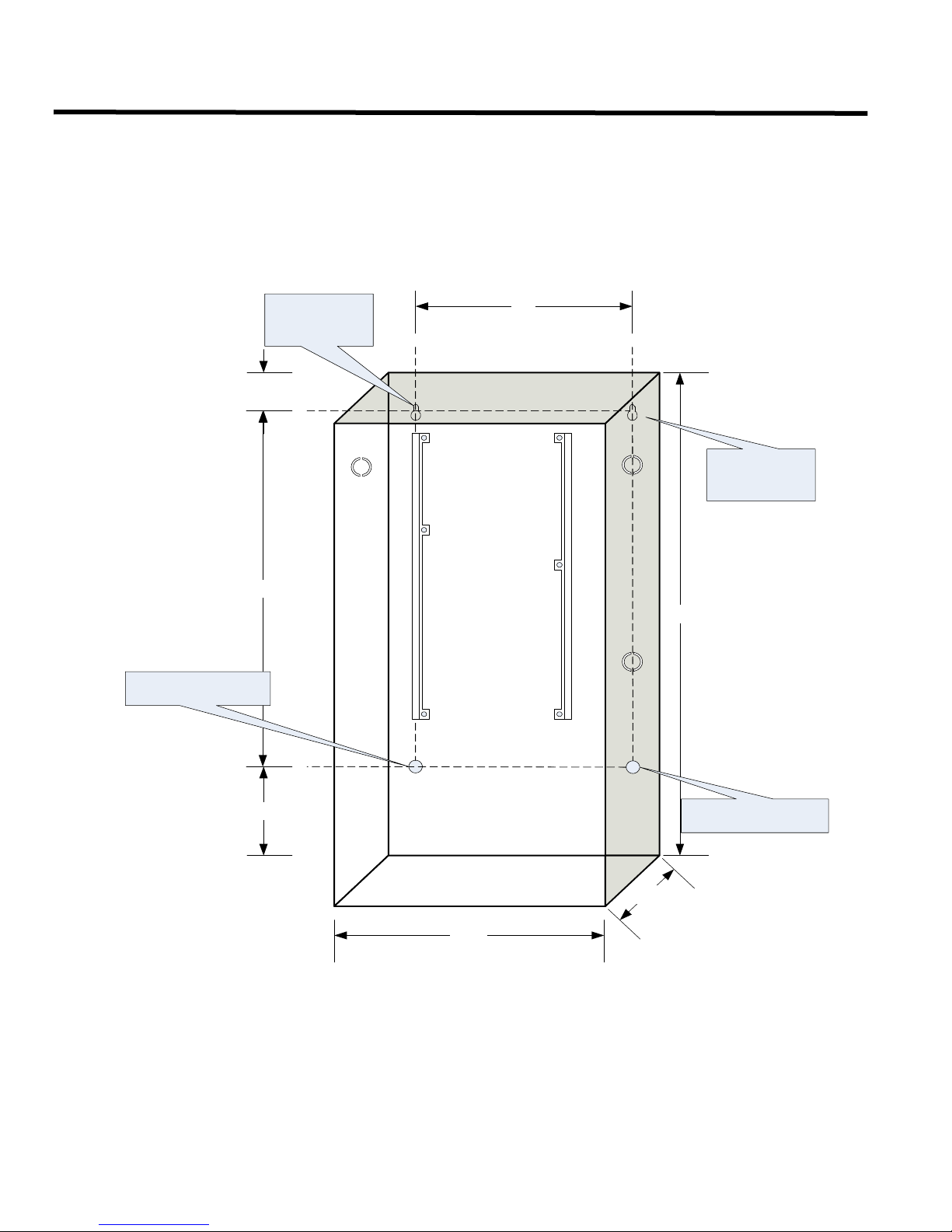
Mechanical Installation
11"
14.5"
1.5"
14.5"
5.4"
4.5"
20"
Mounting
Hole
Mounting Hole
Mounting
Hole
Mounting Hole
Mechanical Installation
Installing the Enclosure
Install the SFC-500 Series Fire Alarm Panel enclosure as shown below. Mount the enclosure using the four mounting
holes and the screws provided.
Figure 1: Wallbox Dimensions / Mounting the SFC-500 - Surface
8
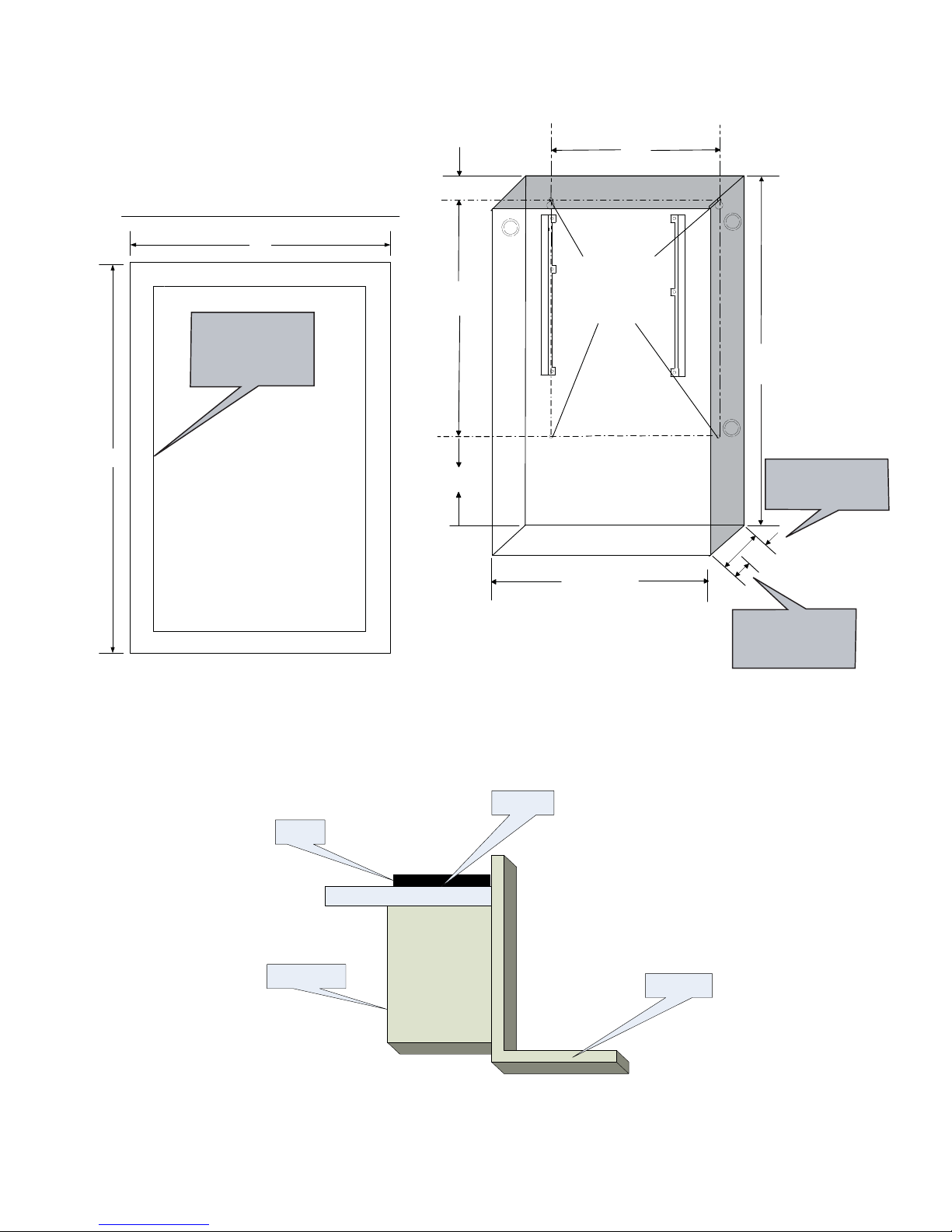
Figure 2: Mounting the SFC-500 - Flush
17"
22.5"
PLACE SFC-200TRB TRIM RING OVER BACKBOX
14.5"
3.5"
1"
4
.
5
"
11"
20.0"
1.5"
4"
14.5"
3.5" is the maxi mum depth
for semi-flush mounting
using the flush tr im ring
1" is the mini mum depth
above the wal l requi red
for semi-flush mounting
using the flush tr im ring
4 Mounting
Holes for
Surface
Mounting
Adhere trim ring to
wall surface around
SFC-500 backbox
Back box
Trim ring
Wall
Wood stud
SFC-500 Series Installation and Operation Manual
The figure below shows a cross-section of the semi-flush mounted backbox and the trim ring. Make sure to allow
a minimum depth of 1” above the wall surface for proper door opening.
Figure 3: Flush Trim Detail
9
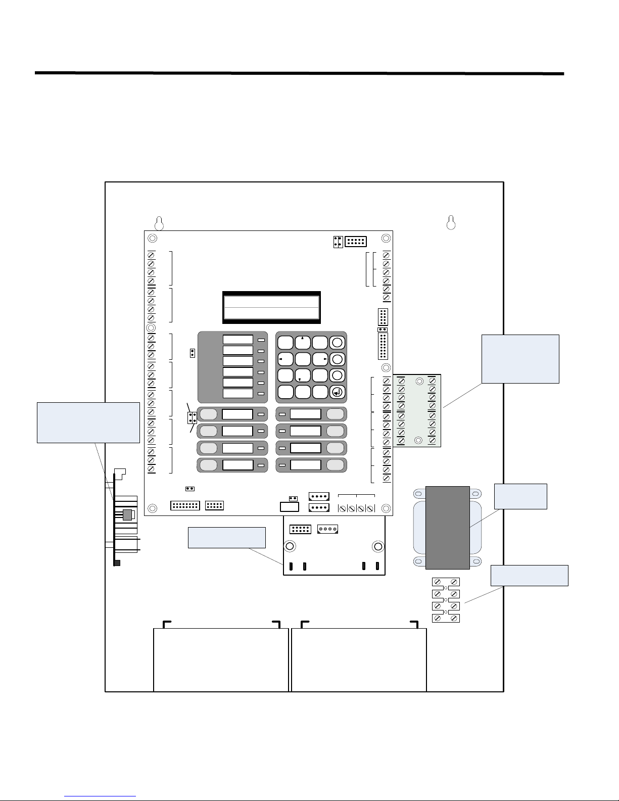
Installing Adder Modules
CLASSA converter
board for indicating
Circuits SOCA-204
(4 circuits)
Reverse polarity and city
tie modu le SPR-200.
Mounted on hex spacer
with two screws p rovide d .
Transformer
AC wiring terminal
-SIG1 OUT+-SIG2OUT+
-SIG1 RET+-SIG2RET+
BLK
RED
BLK
RED
-SIG3OUT+-SIG4OUT+
-SIG3RET+-SIG4RET+
BLK
RED
BLK
RED
P3
BATTERY
P4
+
-
P1
P2
SEC TX
P6 P5
POWER
SUPPLY
Power supply
board
BATTERY
+-
BATTERY
+-
S-+NC NOCNC NOCNC NOCNC NOC RTRT RTRT
RES CO RES CO
LINE1
LINE2
JW7
-+-+
-+-+-+-+
SIG 1SIG 2SIG 3SIG 4
RS-485AUX. RELAY
ALARM
RELAY
SUPERVISORY
RELAY
TROUBLE
RELAY
AUX
SUPPLY
4-WIRE
SUPPLY
COM+COM-TRLTRB
UNFILTERED
FWR 24VDC
RTI
PORT
SYSTEM NORMAL
OCT 21 , 2005 02:41AM
Loop
A
+
-
+
-
B
JW9
JW1
JW3
JW4
SYSTEM
RESET
FIRE
DRILL
ALARM
ACKNOWLEDGE
GENERAL
ALARM
SIGNAL
SILENCE
BUZZER
SILENCE
LAMP
TEST
SPARE
AC ON
1 2
ABC
3
5 6
7 8 9
*
0 #
4
X
M
?
DEF
GHI JKL MNO
PRS
TUV
WXY
QZ
COMMON ALARM
COMMON SUPV
COMMON TROUBLE
CPU FAULT
GROUND FAULT
JW2
JW6
JW5
For PC programming use UIMA
Interface module not UL-864 or
ULC-527 listed. Please refer to
Document LT-929 for details
RS-232C PORT
TO POWER SUPPLY
P12
P3
P2
P8
P4
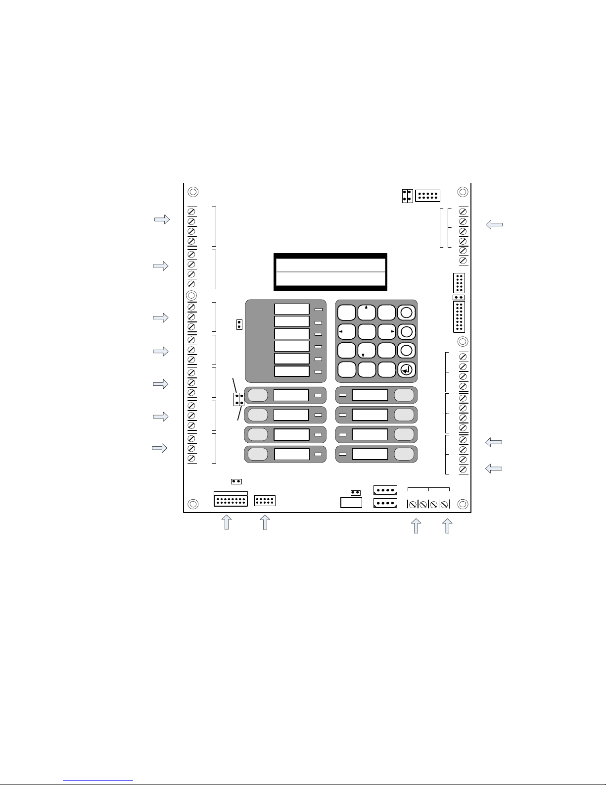
Installing Adder Modules
The SFC-500 Fire Alarm panels come pre-assembled with all components and boards except for Adder Modules.
Module installation locations are shown below. Refer to Figure 5 on the next page for Jumper or DIP Switch settings
and see Wiring Tables and In formation for wiring specifications.
Figure 4: Installation of Adder Modules
10
SFC-500 Series Installation and Operation Manual
Tele p h o n e lin e #1
Tele p hone lin e # 2
RS-485 for
annunciators
Aux ilia ry R elay
Alarm Relay
Supervisory Relay
Trouble Relay
Auxiliary
Supply
Addressable
loop
Resettable
Auxiliary
Supply
Unfiltered
24V supply
Connect to
Remote trouble
indicator
BLK
RED
BLK
RED
BLK
RED
BLK
RED
POWER
SUPPLY
S-+NC NOCNC NOCNC NOCNC NOC RTRT RTRT
RES CO RES CO
LINE1
LINE2
JW7
-+-+
-+-+-+-+
SIG 1SIG 2SIG 3SIG 4
TO SPR-200 MODULE
RS-485AUX. RELAY
ALARM
RELAY
SUPERVISORY
RELAY
TROUBLE
RELAY
AUX
SUPPLY
4-WIRE
SUPPLY
COM+COM-TRLTRB
UNFILTERED
FWR 24VDC
RTI
PORT
SYSTEM NORMAL
OCT 21 , 2005 02:41AM
Loop
A
+
+
-
B
JW9
JW1
JW3
JW4
SYSTEM
RESET
FIRE
DRILL
ALARM
ACKNOWLEDGE
GENERAL
ALARM
SIGNAL
SILENCE
BUZZER
SILENCE
LAMP
TEST
SPARE
AC ON
1 2
ABC
3
5 6
7 8 9
*
0 #
4
X
M
?
DEF
GHI JKL MNO
PRS
TUV
WXY
QZ
COMMON ALAR M
COMMON SUPV
COMMON TROUBLE
CPU FAULT
GROUND FAULT
JW2
JW6
JW5
For PC programming use UIMA
Interface module not UL-864 or
ULC-527 listed. Please refer to
Document LT-929 for details
RS-232C PORT
TO SRAM-332
TO POWER SUPPLY
P12
P3
P2
P8
P4
Connect to
SPR-200
NOT USED
Cable and Jumper Connections for Main Board and Adder Modules
Figure 5: Main Fire Alarm Board Cable Connectors and Jumper Locations
11
 Loading...