

Summit Systems DIGITAL VIDEO RECORDER Operation Manual
SUMMIT SYSTEMS
DIGITAL VIDEO RECORDER
OPERATIONS MANUAL
Summit Systems Digital Recorder - 1 - Operations Manual Ver. 1.0 March 2008

INDEX
3 – 4 Initialising the DVR
5 Getting to know the main screen
6 Information Bar
7 Information Bar (Cont) Question mark Help
8 Control Bar
9 Logging into the DVR
10 Defaulting the screen view layout back to normal
11 Playing back and reviewing records
12 Control Bar (real time snap shot)
13 R.G.B.A (Brightness, Contrast. Etc)
14 Pan, Tilt Zoom (P.T.Z) function (where installed)
15 Playback control
16 – 17 Camera screen, numbers layout
18 Backup Tab
19 Save a Record
20 Save an Image
21 – 24 Copying records to CD / DVD
25 Copying Shots (still images)
26 – 27 SSViewer - CD / DVD playback application
28 T.M.A Timer, Motion Alarm configuration
29 Setup – (Configuring Passwords to log into the DVR)
30 TV-MD (Spot monitor image configuration)
30 Adjust the time (minutes & seconds) – Set time Adjustment
31 – 32 Camera channels Button.
Summit Systems Digital Recorder - 2 - Operations Manual Ver. 1.0 March 2008
INITIALISING THE DVR
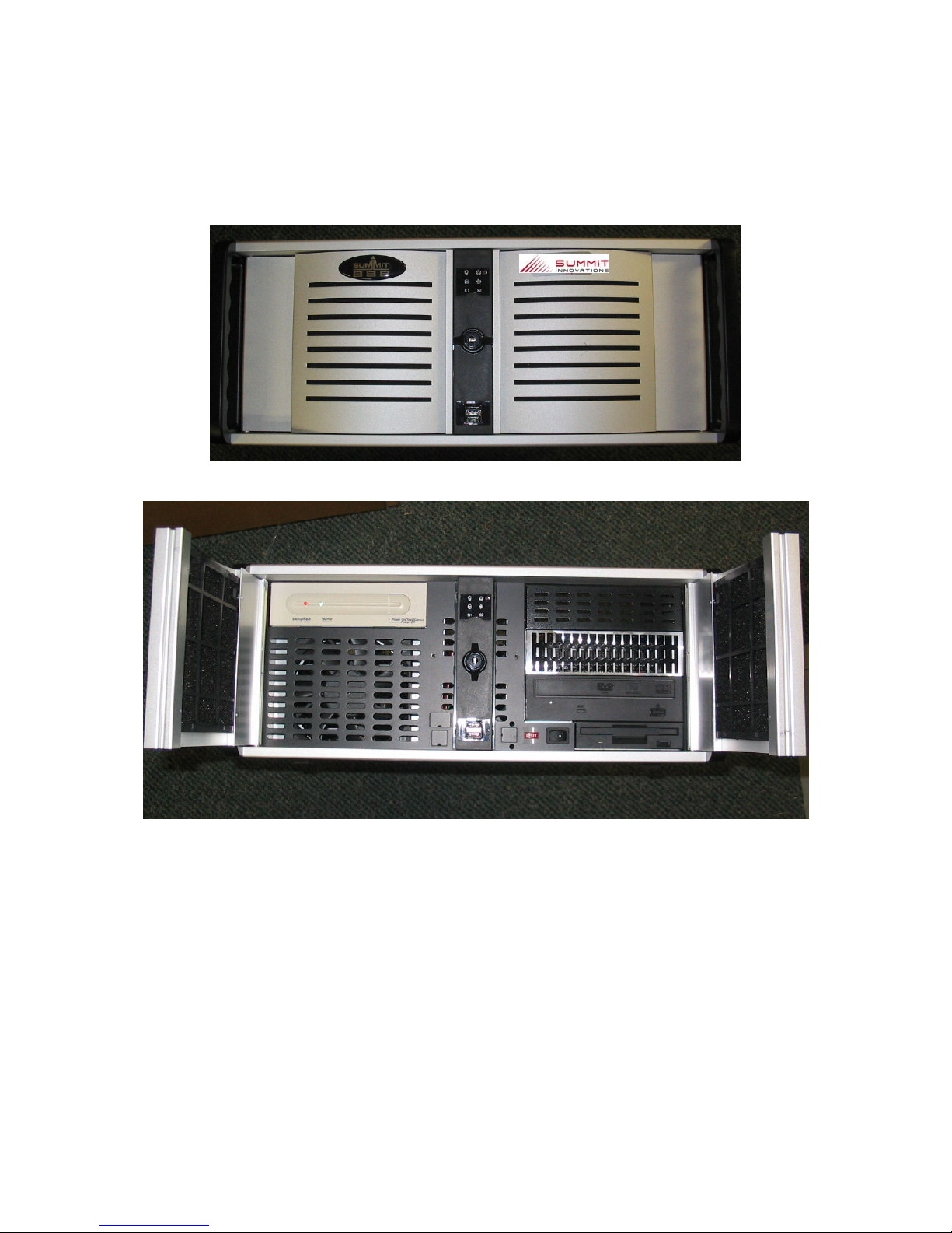
Rotate the centre toggle lock and swing open the right hand door on the front of the DVR unit.
Down the bottom next to the 3½ inch floppy drive, there is a red button with ‘RESET’ on it, and
next to that a black button with a white dot on one side.
Press the white dot on the switch and then release. The switch will spring back to its original
position.
Your DVR will boot up into Microsoft Windows XP and the SS3 software will start automatically.
Summit Systems Digital Recorder - 3 - Operations Manual Ver. 1.0 March 2008
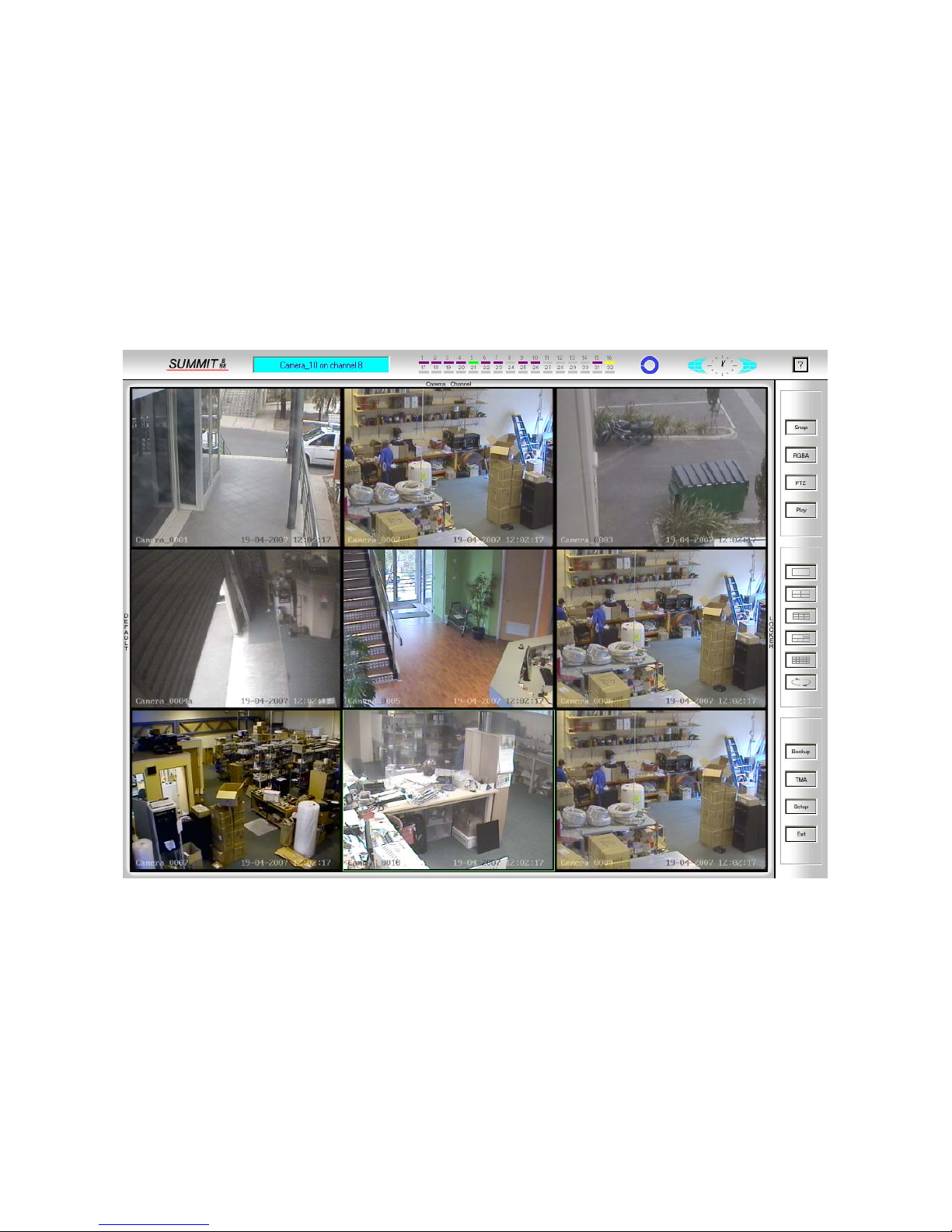
Welcome to the SS3 software! Your screen will look something like this:
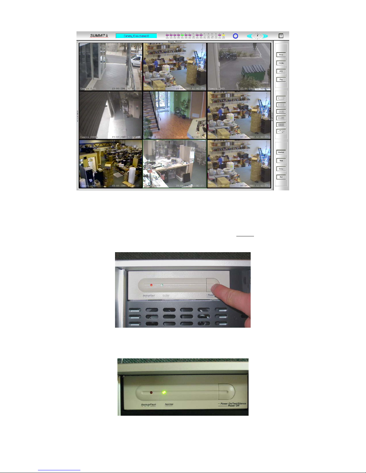
The optional UPS (Uninterruptible Power Supply) with your DVR will be either a cream coloured
or black bay in either the right or left side of the case doors. Ensure that the lights on this device are
illuminated, green for normal operation & red if the unit has been shutdown.
For the DVR to function properly the UPS MUST
be turned on.
To turn the UPS on, press the right hand side of the units raised area on the face, like so:
The red and green lights on the unit will flash on an d you will be left with a permanently on green
light once the unit is active.
Summit Systems Digital Recorder - 4 - Operations Manual Ver. 1.0 March 2008
R
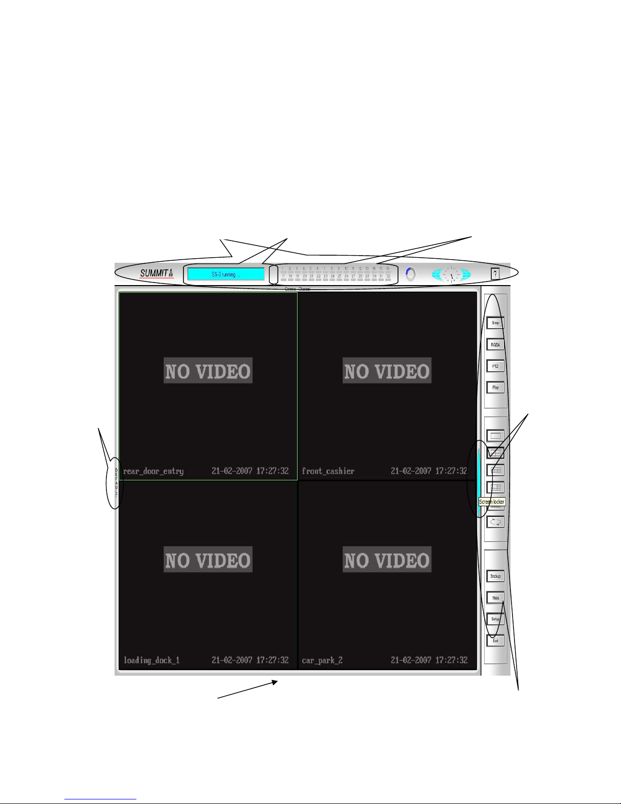
GETTING TO KNOW THE MAIN SCREEN
In order to navigate around the screen you must first understand the screen layout and what tabs and
buttons refer to which areas of the software
The main screen consists of 4 specific areas
INFORMATION BAR at the top of the screen.
CONTROL BAR along the right side of the screen.
VIEWING AREA video images up to 32 channels depending on the size of the system installed.
LOCKER Tab between the Control Bar and the Viewing Area
DEFUALT Tab at the far left of the screen
INFORMATION BAR
OPERATIONS STATUS WINDOW
LOCAL CAMERA RECORDING STATUS
DEFAULT
TAB
VIEWING AREA
CONTROL BAR
LOCKE
Summit Systems Digital Recorder - 5 - Operations Manual Ver. 1.0 March 2008

INFORMATION BAR
The Information Bar shows the following.
SUMMIT 888 logo (hover mouse cursor over the logo to see the current software version)
OPERATIONS STATUS SCREEN.
Changes information such as who has logged in
Which ca mera is currently selected
When you have clicked on System Setup etc.
LOCAL CAMERA RECORDING STATUS
Cameras 1 to 24 or 32 depending on the software version installed.
Will present in a different colour depending on the recording status of each camera
Greyed Out - No camera installed on this channel or TMA not configured (refer Pg-40)
Purple - camera is installed on this channel but not currently recording
Yellow - Camera is recording from motion detection
Green - Camera is set to record from timer at designated times continuously
Red - Camera is being triggered to record from an external alarm source
Green/Yellow – Camera is set to record at 1 frame every second continuos but when motion is
detected in front of the camera it will record at full frame rate until motion ends (usually only used
in gaming facilities)
CURRENT STORAGE ON SYSTEM DRIVES (BLUE/GREY CIRCLE)
As the System Drives fill with stored information (Video Footage) the Blue line will move around
the circle, hover the mouse cursor over the circle to get information on the following
TOTAL VALID SPACE
Shows (In Gigabytes) the Total capacity of storage on the DVR.
AVAILABLE SPACE
Shows the available space (In Gigabytes) of the remaining capacity left for the system to record
onto.
RECORDS SINCE
Shows how far back the earliest records are on the system.
(the DVR is designed to automatically overwrite the earliest recorded records to continue operation,
this means that records from the 1
st
time it began recording will be over written record by record,
systems are generally designed to have the capacity to store records for up to 30 days ((depends on
the size of disk drives and their numbers installed)) when the drives reach their full capacity they
will begin to overwrite the records from 30 days ago ((or earlier)) these records are no longer
retrievable if they have not been backed up I.E. Records Since 04-01-2007 means that the earliest
the records on the system go back to is the shown date.
SYSTEM TIME CLOCK
Shows the current time, hover mouse over clock to see current date, refer to the section on changing
the current time to change minutes and seconds of the system.
Summit Systems Digital Recorder - 6 - Operations Manual Ver. 1.0 March 2008

INFORMATION BAR (Cont)
QUESTION MARK
Left click the mouse cursor once on the Question mark and then click on any tab or box for a text
information screen
Summit Systems Digital Recorder - 7 - Operations Manual Ver. 1.0 March 2008
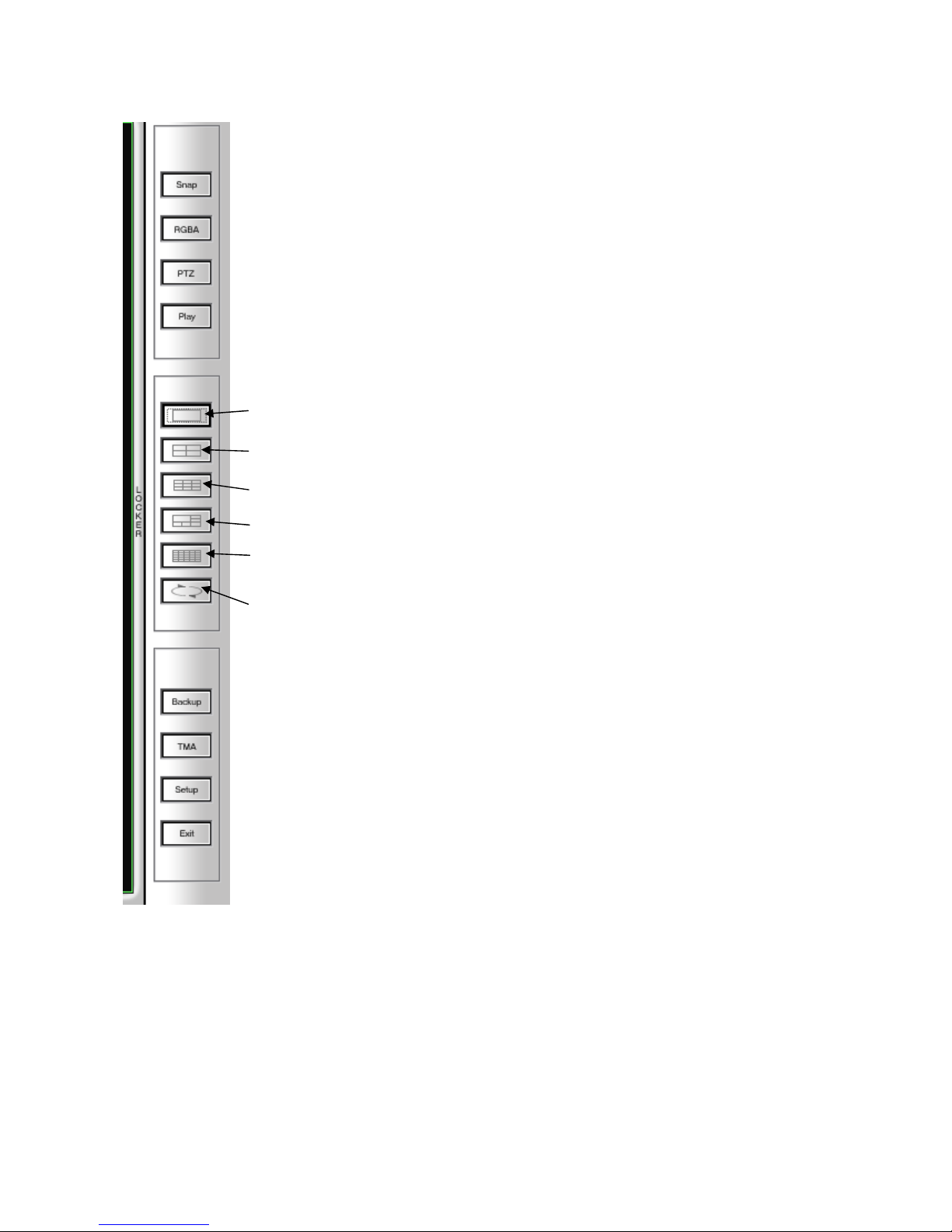
CONTROL BAR
m
The control bar is the heart of the systems controlling functions, here you change camera screen
layouts, setup the system, backup or copy records etc.
SNAP - allows for a real time image snap shot
RGBA - adjusts Brightness, Contrast etc of each individual camera
PTZ - controls the Pan Tilt Zoom Function of a camera (when installed)
PLAY - returns the playback box to the screen when in playback mode
Left click once to show 1 camera in full screen left click again to cycle through
each consecutive camera
Shows 4 cameras on the screen, left click again shows the next 4 cameras etc.
Shows 9 cameras on the screen, left click again to see the next 9 cameras
Shows 1 large and seven small cameras in view
Shows all cameras on the syste
AUTO SEQUENCE - left click once to scroll through the channels
automatically when in 1, 4, or 9 screen views (depends on the number of
cameras installed)
BACKUP - Allows you to copy records and or single images to disk or
CDROM
TMA - sets recording types for Time, Motion or Alarm recording
SETUP - set-up and configuration of entire system (depends on password
access level as to how much setup you will have access to.)
EXIT - Exits the Summit DVR software and returns you to Windows
Interface, note that once Exited the system is no longer recording
Summit Systems Digital Recorder - 8 - Operations Manual Ver. 1.0 March 2008
LOGGING INTO THE SYSTEM
Locker Tab
The ‘Screen Locker’ tab is located on the inside right hand edge of the interface.
It is used to unlock the DVR software, note that software versions 3 and above will automatically
re lock the system after 5 minutes of non activity.
What is ‘Unlocking the screen’? Why do I have to do it?
Unlocking the screen allows the mouse pointer to interact with the buttons on
the screen allowing the user to access the software. Note that the level of
access I.E. what you can do within the software, will be determined by your
Authority level given when the code is set in user manager.
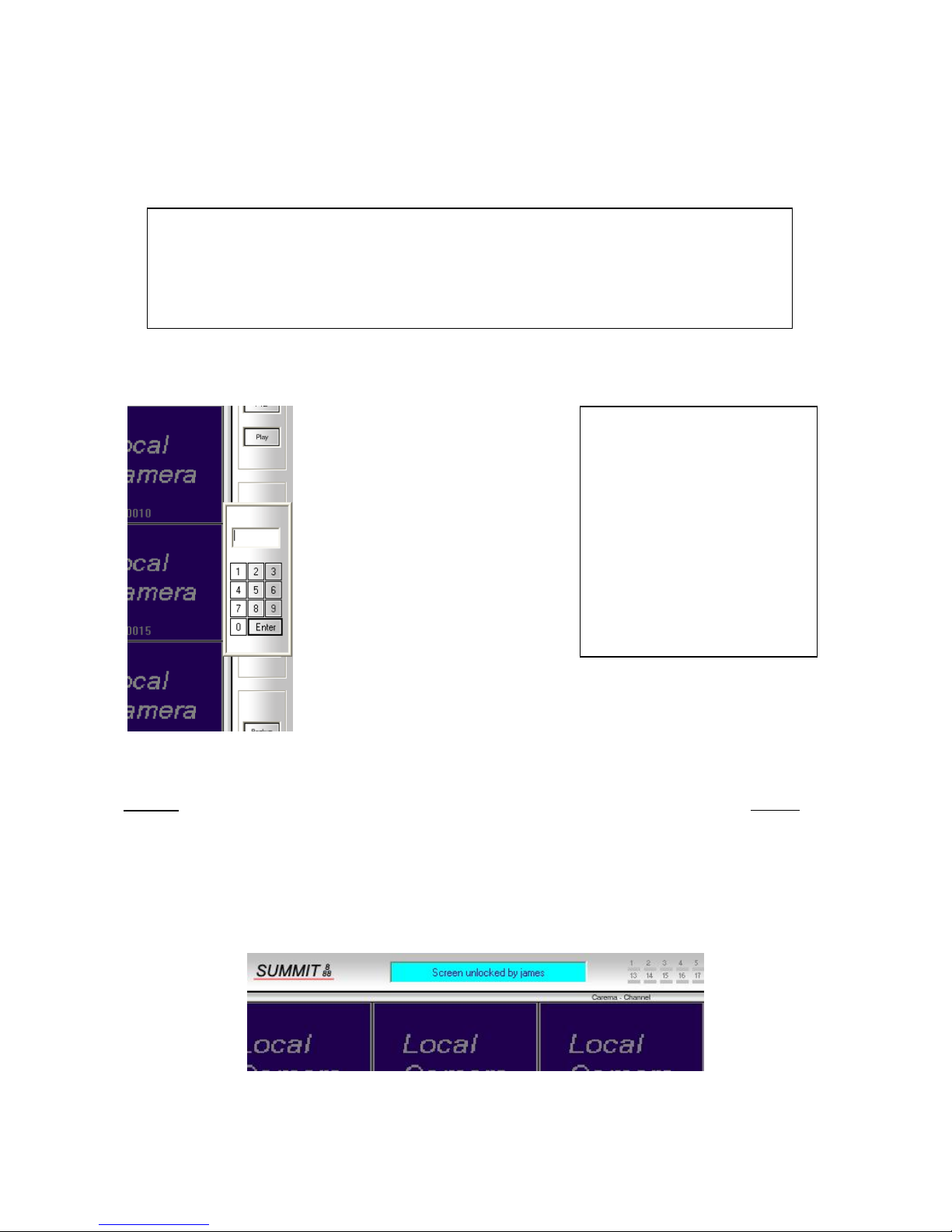
To unlock the screen click the Locker button located on the inside right edge of the interface. The
keypad box will open and allow you to enter your code.
To enter your code simply
click on the corresponding
numbers of your code and
then press the enter
button.
If you make a mistake
entering your code simply
press enter button at
anytime and then click the
‘locker’ button again to re
try.
What is my code?
Where do I get one?
An access code can be
obtained from your
administrator/manager if
you have been granted
access to the security
system. (refer section on
creating user accounts &
their corresponding levels
of access)
NOTE:
done prior to accessing any functions, software versions 3 and above will automatically re lock the
screen after 5 minutes of no mouse or keyboard activity.
Once you have entered your code and pressed the enter button, the light blue screen along the
Information Bar will advise that the screen has been successfully unlocked. The interface buttons
can now be utilised.
Summit Systems Digital Recorder - 9 - Operations Manual Ver. 1.0 March 2008
The locker button is used to gain access to all other buttons on the interface so it MUST be
DEFAULTING THE SCREEN VIEW LAYOUT
Default Tab
The Default Tab is located in the middle of the left hand edge of the screen and is used to reset th e
viewing area to its default setting.
Pressing the Default Tab will “reset” your Camera View layout to real time viewing, that is,
images being viewed are real time and not in playback or review mode.
To reset your screen using the Default Tab make sure the ‘screen is unlocked’ as per previous
instructions, then simply press the Default Tab on the left and the screen will flicker slightly as the
windows view reset to their default configuration.
Note:- for the software versions SS1 and SS2 a simple left mouse
click on the Default Tab will reset the screen, however, for
software version SS3 and above there are more choices when you
click on the Default Tab which allow you to save multiple
variations of screen layouts, to know which software version you
have simply move the mouse cursor over the SUMMIT 888 logo on
the Control Bar and the version and release date will be shown
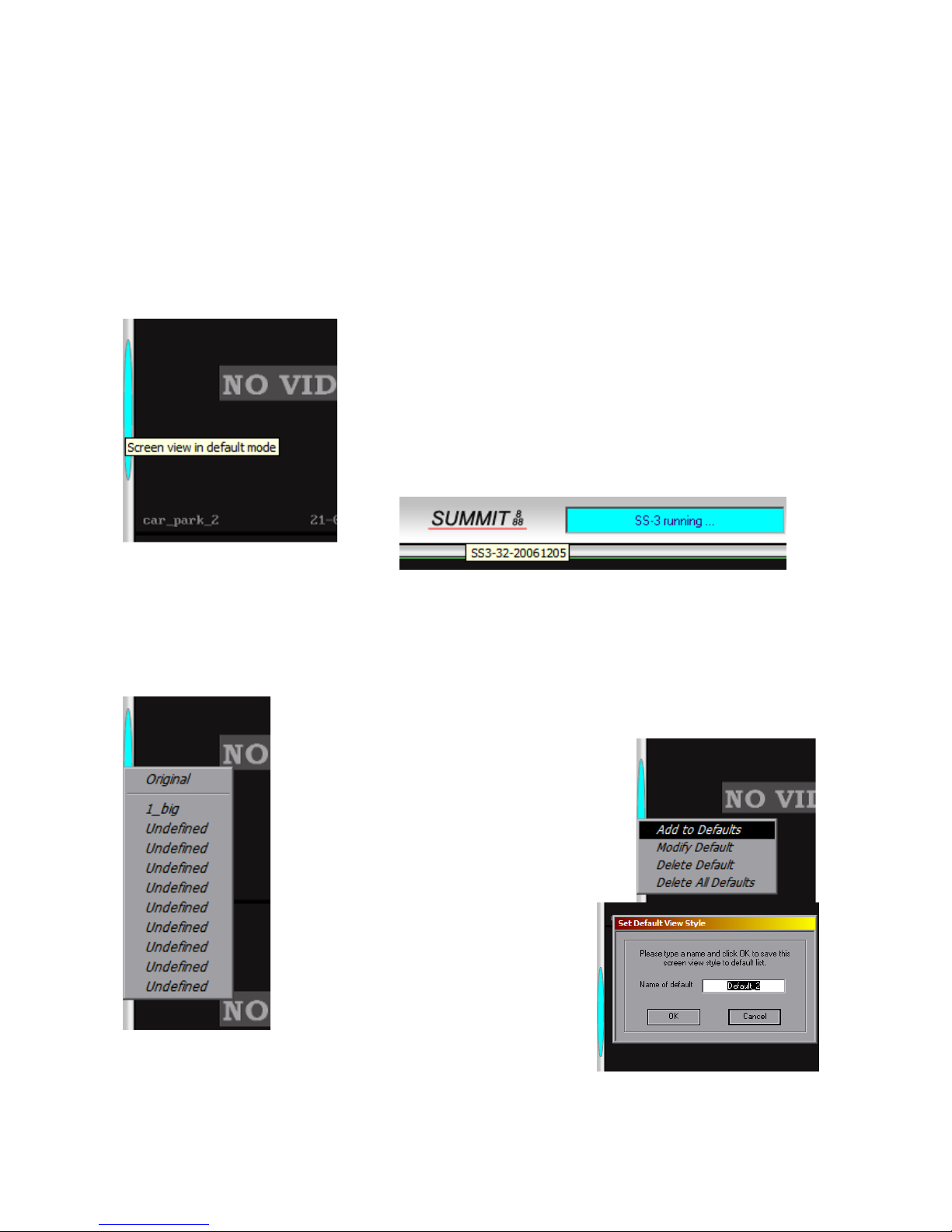
Changing Default View Styles on SS3 and above
Left Click on Default and click on the chosen
screen layout setting, the video screens will
change to suit your choice.
To create your own layouts, right click on
Default and then left click on Add to Defaults,
give the new Default a distinctive name and
click OK.
Summit Systems Digital Recorder - 10 - Operations Manual Ver. 1.0 March 2008
 Loading...