

Page 1
Summit Audio Model TLA-100A
Tube Leveling Amplifier
Operating Manual
IMPORTANT!: CAREFULLY READ THE ENTIRE INSTRUCTION
MANUAL BEFORE HOOKUP OR OPERATION OF THE TLA-100A
WARNING!: HIGH VOLTAGE THIS UNIT CONTAINS NO USER
SERVICEABLE PARTS. SERVICING SHOULD ONLY BE DONE BY
QUALIFIED SERVICE PERSONNEL OR FACTORY. DO NOT OPERATE
THE TLA-100A WITH THE COVERS REMOVED.
Summit Audio, Inc.
1183 Baltic Suite A
Gardnerville, NV 89410
Copyright 1992, 2003 Summit Audio, Inc. ALL RIGHTS RESERVED. Printed in the U.S.A.
Page 2

Doc.# 1085A01
INTRODUCTION
The Summit Audio Tube Leveling Amplifier is a hybrid of technologies. It
contains both vacuum tube and solid state components. This combination
of old and new technologies produces an incredibly warm and smooth
sounding compression device without the inherit disadvantages of the older
designs. Input connections are made using three pin XLR connectors.
Features are as follows:
• EASE OF OPERATION
• “SOFT KNEE” CHARACTERISTIC
• SWITCH SELECTABLE ATTACK AND RELEASE SETTINGS
• SIDE CHAIN ACCESS
• STEREO COUPLING CAPABILITY
• BALANCED INPUT
• 990 BALANCED OUTPUT STAGE
• HAND CRAFTED IN THE USA
Having found this manual, carefully unpack the TLA-100A and its power
cord. Save the carton and packing material, should it be needed. Before
powering the unit read this manual, observing the cautions for HIGH
VOLTAGE. Proceed by doing the following :
• Check the line voltage switch.
• Determine the proper fuse size by referring to the specifications.
• Check for meter illumination and the pilot lamp when the unit is
powered up.
• Note that this unit is wired PIN 2 HOT.
2
Page 3

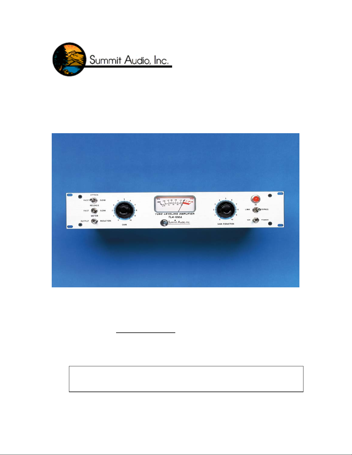
THE CONTROLS
ATTACK SWITCH : A three position switch with fast, medium and
slow settings, which controls the time it takes
the TLA-100A to respond to the input signal.
RELEASE SWITCH: Controls the time it takes the TLA-100A to
return to unity again. A three position switch
with fast, medium and slow settings. The
release time is also effected by the program
material. The slower the release time setting,
the more the program material determines the
release time.
METER SWITCH: Allows monitoring the output level of the TLA-
100A or the amount of gain reduction taking
place.
BYPASS SWITCH: This is a three position switch. In the bypass
position, the TLA-100A is removed from the
audio path. In the middle (or in) position, the
TLA-100A is switched into the audio path. In
the left (or link) position, the stereo link signal
is connected to its back panel connector. This
allows stereo or mono operation of two units by
front panel selection.
GAIN: Sets the voltage gain of the TLA-100A. It
determines the output level, which can be
monitored on the meter.
GAIN REDUCTION: Sets the amount of gain reduction taking place,
and the operating point where gain reduction
begins. The higher the gain reduction, the
higher the ratio becomes.
POWER: A.C. power on and off.
BAL/UNBAL SWITCH: A rear panel switch which changes the output
and metering circuit for proper operation into
balanced or unbalanced loads.
3
Page 4

Attack switch changes the time
(fast, medium, slow) it takes
for the TLA-100A to respond to
input signal.
Release switch adjusts the
time (fast, medium, slow) it
takes for the TLA-100A to
return to unity gain.
Link/In/Bypass switch toggles between
bypass (no compression), in
(compressing) and link mode for
stereo linking with another TLA-100A,
TLA-50, or MPC-100A.
Gain controls the output
level (makeup gain).
Meter switch selects the VU meter to
monitor the output level or gain
reduction taking place.
Gain reduction determines
the amount of gain
reduction taking place on a
signal.
Power switch.
VU Meter monitors output
level or gain reduction.
4
Page 5

TRACKING, LIVE SOUND, MIXING
Plug the TLA-100A into your mixing console’s insert jack or patch bay.
The TLA-100A also sounds great if inserted directly in line after the
preamplifier.
DE-ESSING
Plug a TRS insert cable into the side chain jack on the back of the TLA100A. Plug the send (tip) of the insert cable to the input of an EQ, and the
return (ring) of the cable to the EQ output. Boost the frequencies on the EQ
that you want to compress (de-ess).
DUCKING
Send the output of the “lead” program material into the side chain input
after inserting the TLA-100A on the “background” program material.
Example: Send the output of a vocal mic into the side chain, with the TLA100A inserted on the lead guitar track. As the singer uses the vocal mic, the
lead guitar will decrease in amplitude.
CIRCUIT EXPLANATION
The TLA-100A features a vacuum tube amplifier driving an electronically
balanced 990 output stage. All the signal amplification in the audio path
takes place in the tube circuit. The 990 amplifiers provide a low output
impedance for driving cables and 600 Ω loads. The 990 is a high
performance op amp made of discrete parts, and then potted for thermal
stability.
The input is electronically balanced, and directly feeds the unique
compression cell. The SIDE CHAIN allows for stereo coupling, or the
insertion of an equalizer. Due to the combination of tube and solid state
circuitry long term drift of the compression circuit is minimal and tracking
of two TLA-100As stereo linked is within .3dB.
5
Page 6

ELECTRICAL CONNECTIONS
INPUT:
(This TLA-100A is wired as a pin 2 hot device. Units made before March 1
wired with pin 3 hot.)
Unbalanced: 3 pin XLR Connector Balanced: 3 pin XLR Connector
Pin 1 – Ground Pin 1 – Ground
Pin 2 – (+) Signal Pin 2 – (+) Signal
Pin 3 – Connect to Pin 1 Pin 3 – (-) Signal
st,
2003 come factory
OUTPUT:
Unbalanced: 3 pin XLR Connector Balanced: 3 pin XLR Connector
Pin 1 – Ground Pin 1 – Ground
Pin 2 – (+) Signal Pin 2 – (+) Signal
Pin 3 – Connect to Pin 1 Pin 3 – (-) Signal
SIDE CHAIN:
Tip – Signal output (to EQ)
Ring – Signal input (from EQ)
Sleeve - Ground
Set the rear panel switch for the proper position.
STEREO LINK:
Tip – Signal
Sleeve – Ground
Use the shielded patch cord with ¼” plug
Note: When running an unbalanced output it is best to connect pin 3 to pin
1 in the connector that plugs into the TLA-100A.
The TLA-100A contains heat generating devices, ample ventilation needs
to be provided. Good ventilation will give long, trouble free operation.
THINK TUBES!!
SPECIFICATIONS
6
Page 7

OUTPUT :
+4dBm corresponds to 0 VU. The output is
electronically balance or unbalanced using 990
operational amplifiers. Output impedance is
75 Ω. The recommended output load is
600 Ω or more. Maximum output is +25dBm.
INPUT:
PANEL SIZE:
DEPTH BEHIND PANEL
POWER:
COMPONENTS:
The input is electronically balanced or
unbalanced. Input impedance is 20k Ω.
Maximum input level is +26dBm.
Standard 19” by 3.5” (two units of rack space).
10.5” in addition to users I/O cabling
:
35 watts.
115-230 Volt.
50 or 60 Hz.
Fuse size is .5 amp for 115 volt and
.25 amp for 230 Volt.
1 x 12AX7A Vacuum Tube
2 x high reliability 990 operational amplifiers
13 x integrated circuits
3 x transistors
1 x compression cell
.
SHIPPING WEIGHT:
To operate this unit on 115 volts, switch the line voltage selector on the
back of the unit to read 115 volts and confirm that the external fuse
(mounted in chassis) is a [3 AG ½ Amp slow blow].
To operate this unit on 230 volts, switch the line voltage selector on the
back of the unit to read 230 volts and confirm that the external fuse
(mounted in chassis) is a [3 AG ¼ Amp slow blow].
16 Lbs.
7
Page 8

OPERATION
The first step in the operation of any device using a vacuum tube is to apply
power and let the unit fully warm up (15 minutes). After warm up, set the
Gain Reduction control to 0 and adjust the Gain control for 0 VU on the
meter. Switch the Attack to slow and the Release to fast. Now adjust for
the desired amount of Gain Reduction and recheck the output level.
As the amount of Gain Reduction is increased, the processed audio follows
a smooth reduction curve, thereby changing the compression ratio. In this
way, compression may be easily controlled.
If a large peak is detected, the unit will automatically increase the
compression ratio to keep the audio output controlled. If a low
compression ratio is desired, turn the Gain Reduction control until the
meter indicates a small amount of Gain Reduction.
If a higher ratio is desired, set the Gain Reduction control so the meter
indicates a high amount of Gain Reduction. Try different Attack and
Release setting, depending upon the program material and the desired
effect.
8
Page 9

STEREO INTERCONNECT
Insertion of a cable, with a ¼” plug on each end, into two TLA-100As will
operate them in stereo for mastering tapes and compressing other program
material. To operate the TLA-100A in stereo, set the Attack and Release
switches the same, and set the Gain Reduction control to the same level on
both units. The channel with the strongest peak will override both units.
The easiest way to do this is to set the Gain Reduction of each unit before
they are stereo linked, then put the Bypass switch on each unit into the link
position. To disable the stereo link, only one switch needs to be in the nonlinked position.
SIDE CHAIN INSERTION
This connection allows for the insertion of an equalizer in the Side Chain.
By doing this, the TLA-100A becomes frequency selective. Program
material with large amounts of low frequency may have the low
frequencies attenuated in the Side Chain, causing the low frequency content
to not affect the Gain Reduction. High frequency response of the Side
Chain may be boosted to help prevent high frequency overload; it becomes
a “de-esser” in this mode.
9
Page 10

Allow the TLA-100A to warm up for at least 15 minutes before using it in
your processing chain. The tubes and other circuitry need time to reach an
electronic equilibrium before they will operate at optimal specifications.
For the longest life, it is recommended that you turn off the unit when it is
not in use.
Please mount the unit in your rack, making sure that there is sufficient
ventilation, especially on the right and left side of the chassis. The
TLA-100A will generate a significant amount of heat; therefore, it is
necessary to have good air flow to prevent damage to your TLA-100A or
any other pieces of gear housed in the rack with it.
The tubes in your Summit Audio TLA-100A have been intensely screened
for desired distortion and gain characteristics. We recommend that you do
not replace the tubes with “guitar amp” tubes. Please consult your dealer
about availability of appropriate replacement tubes. These can also be
ordered directly from Summit Audio.
Please fill out the warranty info at www.summitaudio.com for a full threeyear warranty on your TLA-100A. If you have any questions about the
operation of your TLA-100A, please do not hesitate to call our Customer
Service Department at 775-782-8838 or contact us on the internet at:
sound@summitaudio.com.
10
 Loading...