

Page 1
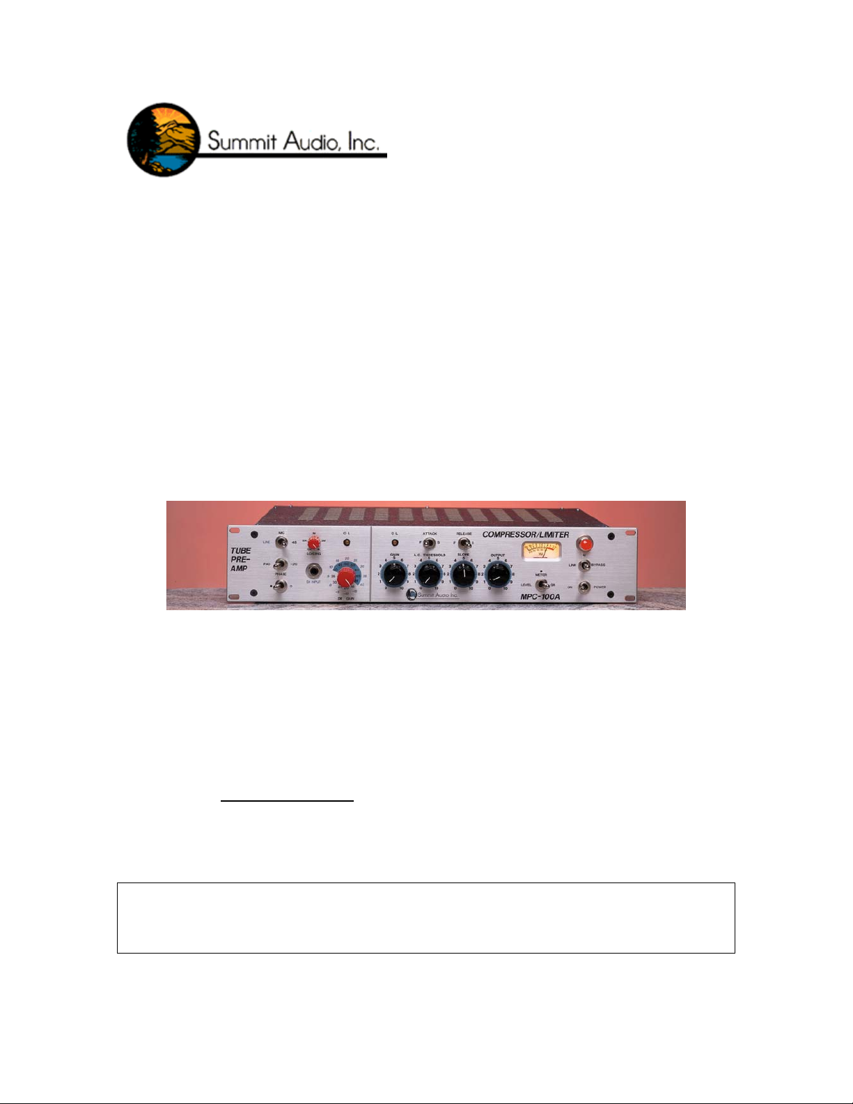
Summit Audio Model MPC-100A
Mic Preamp/ Compressor
Operating Manual
IMPORTANT!: CAREFULLY READ THE ENTIRE INSTRUCTION MANUAL
BEFORE HOOKUP OR OPERATION OF THE MPC-100A.
WARNING!: HIGH VOLTAGE. THIS UNIT CONTAINS NO USER SERVICEABLE
PARTS. SERVICING SHOULD ONLY BE DONE BY QUALIFIED SERVICE
PERSONNEL OR FACTORY. DO NOT OPERATE THE MPC-100A WITH THE
COVERS REMOVED.
Summit Audio, Inc.
1183 Baltic Suite A
Gardnerville. NV 89410
Copyright 1997, 1999 Summit Audio Inc. ALL RIGHTS RESERVED. Printed in the
U.S.A. Doc.# 523A00
Page 2

Product Introduction
The Summit Audio MPC-100A Mic Preamp/ Compressor-Limiter is a single
channel tube preamp and tube compressor/limiter all in a two-space
rackmount unit. It accepts line, microphone, and Hi-Z input signals. The
preamplifier provides a warm yet crisp vacuum tube tone. The
compressor/limiter section has very fast attack times, making it ideal for
optimizing signal prior to entering the digital domain. In addition to having
superb sound and a user friendly interface, the MPC-100A has the robust
build quality consistent with the Summit Audio family of products.
Features include:
Mic, Line and Hi-Z inputs
“Clean” to “Saturated” tube sounds
Tube drive indicators
Unique Hi-Z instrument DI with impedance matching control
Two stages of tube amplification
3 position “smart” attack and release switches
High quality true VU meter
Continuously variable level control
+4 dB balanced and –10 dB unbalanced outputs (useable simultaneously)
Stereo linkable to another MPC-100A or TLA-100A
Jensen Mic transformer
990, discrete output stages
Hand crafted in the USA
Having found this manual, carefully unpack the MPC-100A and it’s power cord. Save the
carton and packing material should it be needed for future shipping. Before powering the
unit, read this manual. Please observe the cautions for HIGH VOLTAGE. Proceed by
doing the following:
1. Set the line voltage switch to the proper position
2. Determine the proper fuse size by referring to the specifications
3. Check for pilot illumination when powered up
Page 3

THE CONTROLS
1. Line/Mic/48 3 position switch selects the input being used, line or mic, and also
engages the phantom power +48 volts for condensor microphones
2. Pad/-20 2 position switch engages 20 dB of input signal attenuation
3. Phase/180 2 position switch engages a 180 degree phase shift of the signal
4. DI Input 1/4" mono jack accepts Hi-Z instruments such as electric guitars
and basses; a direct input into the preamp tube, bypassing the input
transformer
5. Loading variable resistor for impedance matching of the Hi-Z input (range
is 10k to 1M ohms); adjust for desired upper harmonic content in
guitar sound
6. Gain 12 position rotary switch controls signal gain in the input preamp only
note: for Hi-Z input only top 7 positions have any effect (as shown in
blue)
7. OL left yellow LED indicates preamp vacuum tube saturation; when
LED is blinking, the tube is just entering soft clipping
Compressor Section Controls:
8.Gain variable resistor controls compressor vacuum tube gain
9. OL right yellow LED indicates compressor vacuum tube saturation; when
LED is blinking, the tube is just entering soft clipping
10. A.C. Threshold variable resistor sets the signal amplitude threshold, above
which compression engages
*NOTE!!! A setting of 10 yields the least compression, whereas a setting of 0
yields the most compression
11. Slope variable resistor controls the magnitude of compression (sometimes
referred to as ratio); a setting of 10 yields maximum compression,
whereas a setting of 0 yields the least compression
12. Attack 3 position switch selects fast, medium, and slow compression response
time to input signal peaks; this is how fast the compression can kick in
13. Release 3 position switch selects fast, medium, and slow compression release
time; this is how long it takes the compressor to stop attenuating signal
Page 4

Output Section Controls:
14. Output variable resistor controls overall output signal level; this is a post-
preamp and post-compressor gain control preceding the 990 discrete solid
state output
note: this feature enables the user to saturate both the preamp
tube and the compressor tube while still maintaining a proper signal level
sending to other devices - i.e. recording media
15. Level/G.R. 2 position switch selects the VU meter's mode of operation;
in level mode, the meter indicates peak amplitude of output signal; in G.R.
mode, the meter indicates the gain reduction is being applied to the signal
note: this meters right to left from 0 VU
16. Link/In/Bypass 3 position switch selects stereo linked compression, compression
engaged, or bypass compressor (preamp by itself)
note: when linking two MPC-100A's for stereo operation, the unit
which is set for the most compression will act as the controller for both
units; also, a 1/4" mono connection is required between units
Back Panel Connections:
Mic Input female XLR jack for microphone signal in
Line Input female XLR jack for line level signal in (Pin 3 is + of balanced pair)
Side Chain 1/4" stereo jack for balanced signal in for ducking and d'essing
Stereo Link 1/4" mono jack to connect two MPC-100A's for stereo compression
-10 dB Output 1/4" mono jack for low level -10 dB unbalanced signal out
+4 dB Output male XLR jack for pro level +4 dB balanced signal out (Pin 3 is hot)
Page 5

1. 5. 7.
9.
12.
13.
15.
16.
2.
3. 4.
6.
8.
10. 11. 14.
Page 6

Use Scenarios and set up
Recording and compressing a stereo mix: Insert a ¼” patch cord into the
stereo link jack on the back of two MPC-100A’s (or a TLA-100A). Set both
MPC-100A’s to Link mode and to line input. Whichever one is set for more
compression will act as the master (slope and threshold are the only controls
affected). Insert the MPC-100A into the main inserts on the console, with
the send from the console to the line level input, and the return from the
–10 dB output of the MPC-100A.
Getting tube guitar distortion: Plug the output of the guitar into the Hi-Z
input on the front of the MPC-100A. Set the impedance loading high (try
0.5M ohms). Turn the output low. Turn the preamp gain up to +60 or more
and play the guitar. The Tube Drive light should be blinking or steady
yellow. Turn the compressor gain up to 6 or more, and the associated Tube
Drive light should also be yellow. Set the compressor to your favorite
settings (try Threshold –5dB and Slope 5 with a fast attack and release time),
then slowly turn up the output until you reach the desired recording/
monitoring level.
Getting a clean microphone signal: Plug the microphone into the mic input
on the back of the MPC-100A and set the input switch to mic (or 48 for
condensor mics needing 48 volt phantom power). Make sure both the
preamp and compressor gains are turned all the way down. Turn the output
gain up very high, then slowly turn up the preamp gain and compressor gain
to the desired recording/ monitoring level. Set the compressor to your
desired settings (try threshold 0 dB, slope 5.5 with fast attack and medium
release times).
Getting a warm bass tone: Plug the bass directly into the Hi-Z input. Turn
the Output knob very low. Set the Loading to about .1M ohm and turn the
preamp gain up until the Tube Drive light just starts to flash while the bass is
being played (the flashing light indicates soft clipping). Increase the
compressor gain until that Tube Drive just starts to flash occasionally, and
set the compressor to the desired settings (try –10 dB threshold, a slope of 5,
with fast attack and medium release). Turn the output knob until you achieve
the desired recording/ monitoring level. This can also be done if the bass is
plugged into a DI box. Just take the XLR out of the DI into the Mic input on
the MPC-100A, and set the input switch to Mic.
Page 7

De-essing: (Requires external EQ) Plug a TRS insert cable into the side
chain jack on the back of the MPC-100A. Plug the send (tip) of the insert
cable to the input of the EQ, and the return (ring) of the cable to the EQ
output. Boost the frequencies on the EQ that you want to compress (de-ess).
Ducking: Send the output of the “lead” program material into the side chain
input after inserting the MPC-100A on the “background” program material.
Example: Send the output of the lead guitar mic into the side chain, with the
MPC-100A inserted on the rhythm guitar track. As the lead guitar player
plays, the rhythm guitar will decrease in amplitude. This is perfect for
broadcast use when the DJ needs to speak over music, live use when the lead
singer needs to be heard over the lead guitar, or film sound when an actor’s
voice has to overcome a noisy background tone.
Page 8

Further Notes……
Linking: use a 1/4" mono patch cord with tip~signal and sleeve~ground; the MPC-
100A which is set for more compression will act as the master controller for both units;
slope and threshold are the only controls effected [note: an MPC-100A can also be linked
to a TLA-100A]
Side Chain Insertion: use a 1/4" stereo patch cord with tip~send, ring~return, and
sleeve~ground; to execute "ducking" (compression of principle audio signal, triggered
by an external audio signal) tie tip and sleeve to ground, and bring the triggering signal in
on the ring; to execute "de-essing" (engaging a frequency dependence in the compression
of the principle signal) send to the outboard equalizer on the tip, return from the EQ to
the compressor on the ring and tie the sleeve to ground - then boost the frequency you
want to compress and roll off the frequencies you want uncompressed; this can be
particularly useful in removing sibilance from vocal tracks.
Sleeve Ring Tip
Ground
Side Chain EQ
Input Output
Side Chain connections are unbalanced
Unbalanced Connection: to go into the line input XLR jack of the MPC-100A
unbalanced, it is necessary to connect the signal to pin 3 and tie pin 2 and pin 1 to
ground; unbalanced out has its own dedicated 1/4" mono jack
Tonality: because there are two stages of vacuum tube gain in the MPC-100A as well as
a discrete, solid state gain stage, the range of tonality in the unit is significantly wide; we
recommend that you experiment with moderately overdriving either or both of the tubes
and compensating for desired output level using the discrete gain control; be aware that
when one of the yellow LED's comes on, it is indicating that the signal is reaching soft
clipping "saturation" in the vacuum tube; for the most transparent signal tone set the solid
state gain to maximum and adjust the tube gains only as high as your necessary output
level requires.
Page 9

A Word About Tubes
The tubes that are used in the MPC-100A are selected to give the best possible
performance in the position that they are in the circuit. Switching them to
different positions might cause performance deterioration of the audio path.
Replacing them with “gold” or high end tube types may not be desirable. In cases
that we have measured, these tubes have shown higher distortion and noise
compared to the tubes we have selected. In some cases, the so called “gold” or
high end tubes have made the unit unusable. The reason for this is some of the
“gold type” tubes are selected for high distortion in guitar amplifiers. Using gold
tubes is no guarantee of better performance. All of these so called “Brand X”
types are selected with 6.3 volts AC on the filaments, whereas Summit Audio
uses 5 volts DC on the heaters for longer tube life and lower noise. The reduced
gain may raise the noise floor, increase distortion, and reduce headroom.
For proper performance from a tube, the replacements must be selected using 5
volts DC on the filaments. The tubes we use are selected in the circuits that they
are used in to ensure proper operation, long life, and low distortion and noise.
In at least 50% of the cases we have tested, gear that has been used for several
years actually has lower noise and distortion levels than when new. This makes
the question of when to replace tubes difficult to answer. If a tube turns microphonic, the distortion will be obvious and the tube must be replaced. However,
tube life will most likely be greater than 10,000 hours of operation. Tubes are
generally very reliable; don’t replace them just because they are old. In the MPC100A there are gain adjustments that will need to be checked when the tubes are
replaced, or else the metering could become inaccurate and the noise floor could
change. Replacement should be done on the bench with a distortion analyzer
attached to ensure that the distortion levels are proper and it is comprised of
second order harmonics.
Before replacing the tubes in your MPC-100A, please talk to your dealer, call
Summit Audio, or find a technician who has experience working with tubes and
high end audio equipment.
Page 10

Electrical Connections:
(This MPC-100A is wired as a pin 2 hot device. Units made before March 1
st,
2003 come
factory wired with pin 3 hot.)
Input:
Unbalanced: 3 pin XLR Connector Balanced: 3 pin XLR Connector
Pin 1 – Ground Pin 1 – Ground
Pin 2 – (+) Signal Pin 2 – (+) Signal
Pin 3 – Connect to Pin 1 Pin 3 – (-) Signal
Output:
Unbalanced: 3 pin XLR Connector Balanced: 3 pin XLR Connector
Pin 1 – Ground Pin 1 – Ground
Pin 2 – (+) Signal Pin 2 – (+) Signal
Pin 3 – Connect to Pin 1 Pin 3 – (-) Signal
Note: When running an unbalanced output it is best to connect pin 3 to pin 1 in the
connector that plugs into the MPC-100A.
Allow the MPC-100A to warm up for at least 15 minutes before using it in your
processing chain. The tubes and other circuitry need time to reach an electronic
equilibrium before they will operate at optimal specifications. For the longest life, it is
recommended that you turn off the unit when it is not in use.
Please mount the unit in your rack, making sure that there is sufficient ventilation,
especially on the right and left side of the chassis. The MPC-100A will generate a
significant amount of heat; therefore, it is necessary to have good air flow to prevent
damage to your MPC-100A or any other pieces of gear housed in the rack with it.
The tubes in your Summit Audio MPC-100A have been intensely screened for
desired distortion and gain characteristics. We recommend that you do not replace the
tubes with “guitar amp” tubes. Please consult your dealer about availability of
appropriate replacement tubes. These can also be ordered directly from Summit Audio.
Please fill out the enclosed warranty card. If you have any questions about the operation
of your MPC-100A, please do not hesitate to call our customer service department at
775-782-8838 or contact us on the internet at: sound@summitaudio.com.
Page 11

Note on specifications: Summit Audio is uncompromisingly committed to excellence. All
of our specifications are made with the latest technology and are UNWEIGHTED
measurements. What does this mean? When measurements are “weighted” (e.g. “A”
weighted, dB (B), dB C weighted, etc.), the measurement devices are basically EQed or
filtered before the measurement is taken. This filtering was developed so that sound
pressure level (SPL) measurements can more nearly match human’s non-linear hearing
characteristics. However, when used in noise, frequency response, and distortion
measurements, weighting will alter the results. Completely flat frequency measurements
are key to giving accurate specifications. Summit Audio devices are the highest quality
professional audio gear and the specifications below are made with the flattest possible
unweighted measurements, giving the most accurate results.
Specifications:
• Output: +4 dBu corresponds to 0 VU. The output is balanced or unbalanced using 990
operational amplifiers. Output impedance is 75 Ω. The recommended output load is
600 Ω or more. Maximum output is +25 dBu.
• Input: The input transformer is balanced. The mic input impedance is 1500 Ω. The
line level input impedance is 40 kΩ and the Hi-Z input impedance is one mega-ohm.
The mic and line inputs are balanced and the Hi-Z input is unbalanced.
• Frequency Response: 5 Hz to 65 kHz
• Noise: Less than –80 dBu at unity gain from 20 Hz to 20 kHz
• Distortion: Less than 0.05% at +4 dBu from 20 Hz to 20 kHz
• Attack Time: 0.75 mS, 6.5 mS, 35 mS
• Release Time: 30 mS, 90 mS, 2.5 S
• Slope: Adjustable from 1:1 to10:1
• Panel Size: Standard 19” by 3.5” (2 units of rack space)
• Depth: 10.5”
• Power: 35 watts, 115 or 230 volts, 50 or 60 Hz
• Fuse Size: 0.5 Amp for 115 VAC, 0.25 Amp for 230 VAC
• Shipping Weight: 18 lbs. (8.17KGs)
To operate this unit on 115 volts, unplug the unit, switch the line voltage selector on the
back of the unit to read 115 volts and confirm that the external fuse (mounted in chassis)
is a [3 AG ½ Amp slow blow]. To operate this unit on 230 volts, switch the line voltage
selector on the back of the unit to read 230 volts and confirm that the external fuse
(mounted in chassis) is a [3 AG ¼ Amp slow blow].
 Loading...