

Page 1

MPE-200/EQ-200
by
Guide To Operations
for firmware version 2.19-2.23
Page 2
Page 2 MPE-200 Guide to Operations
Important Safety Instructions
Always follow these basic safety precautions when using the MPE-200:
1) Read all the instructions before using the MPE-200. Keep these instructions.
2) Do not block or obstruct the ventilation holes in the side, or the fan opening at the
rear. Locate it away from heat sources such as heat registers, or other products that
produce heat.
3) If the MPE-200 is mounted in a rack case for portable use, rear support brackets
must be provided.
4) The MPE-200 in combination with an amplifier and speakers or headphones might
be capable of producing sound levels that could cause permanent hearing loss. Do
not operate for a long period of time at a high sound level or at a level that is
uncomfortable.
5) The MPE-200 has no user-serviceable parts other than the rear panel fuses. In event
of any of the following, please contact an authorized Summit service station:
• The MPE-200 does not appear to be operating normally or exhibits a marked
change in performance;
• It has been dropped, or the enclosure damaged;
• Liquid has been spilled into it or if it has been exposed to rain.
WARNING:
TO REDUCE THE RISK OF FIRE OR ELECTRIC
SHOCK, DO NOT EXPOSE THIS APPLIANCE TO
!
!
!
!
!
!
RAIN OR MOISTURE.
ATTENTION:
POUR EVITER TOUS RISQUES D'INCENDIE OU DE
DECHARGE ELECTRIQUE, NE PAS EXPOSER A LA
PLUIE OU A L'HUMIDITE.
Grounding Instructions
Improper grounding can cause a risk of electric shock. Check
with a qualified service person or electrician if you doubt the
product is properly grounded.
The MPE-200 must be grounded. In the event of a malfunction,
grounding provides a path of least resistance for electric current to reduce
the risk of electric shock. This product is equipped with a cord having a
grounding conductor and a grounding plug. The plug must be plugged
into an electric supply outlet that is properly installed and grounded in
accordance with all local rules and electrical standards. Protect the power
cord from being walked on or pinched particularly at plugs, convenience
recepticals, and the point where they exit from the apparatus.
Page 3

MPE-200 Guide to Operations Page 3
TABLE OF CONTENTS
IMPORTANT SAFETY INSTRUCTIONS.....................................................................2
GROUNDING INSTRUCTIONS .....................................................................................2
1. UNPACKING AND CONNECTING .......................................................................4
AUDIO
CONNECTIONS ....................................................................................5
2. SYSTEM OVERVIEW..............................................................................................6
CHANNEL
STATUS...........................................................................................8
3. INPUT SCREENS......................................................................................................9
MIC
GAIN SCREEN (GREEN).................................................................................9
HP/LP FILTER SCREEN (AMBER).......................................................................10
INPUT SETUP SCREEN (YELLOW)......................................................................11
4. EQUALIZER SECTION.........................................................................................12
EQUALIZER
OVERVIEW................................................................................12
BOOST / CUT CONTROL.................................................................................12
FREQUENCY
CONTROL.................................................................................12
Q CONTROL......................................................................................................13
5. MASTER SCREENS................................................................................................14
MASTER
CHANNEL SELECT.........................................................................14
EQ GAIN TRIM.................................................................................................14
MASTER PRESET SCREEN (AMBER).................................................................15
MASTER SETUP SCREEN (YELLOW).................................................................15
OUTPUT FADER SCREEN (DARK GREEN)..........................................................17
6. MIDI..........................................................................................................................18
7. SLEEP MODE..........................................................................................................19
8. FUSE AND VOLTAGE SELECTION...................................................................20
FUSE
VOLTAGE
INSPECTION OR REPLACEMENT......................................................20
SELECTION.................................................................................211
9. REGISTRATION...................................................................................................212
Page 4

Page 4 MPE-200 Guide to Operations
1. UNPACKING AND CONNECTING
1.1 Carefully unpack the unit and report any shipping damage
promptly to your Summit dealer and to the carrier.
1.2 The MPE-200 is normally shipped set up for 115 volt AC
(100-125 volts is OK).
For 200-230 and 230-250 volt AC operation, the rear
panel voltage selector should be set to 240v. The fuses
!
!
!
!
!
!
1.3 Turn the unit on by using the rocker switch at the rear power
1.4 Due to its Class A circuit design, the MPE-200 will run warm.
Be careful not to block the vent holes on the right side
!
!
!
should be slow-blow type, 0.8 amp for 90-125v or 0.4
amp for 200-250v.
ATTENTION:
UTILISER UN FUSUBLE DE RECHANGE DE MEME TYPE
DE 0.8 A - 90-125v, 0.4 A - 200-250v.
ATTENTION:
DEBRANCHER AVANT DE REMPLACER LE FUSIBLE.
For more information on fuses and voltage selection, see
section 8 at the back of this manual.
entry. For rack mounting, leave this power switch on, and use
the front panel Sleep control to turn off or on. See section 7
for details.
Its quiet, low-speed fan ensures safe operation over a wide
range of ambient temperatures.
panel or the fan opening on the rear of the MPE-200.
Page 5

MPE-200 Guide to Operations Page 5
1.5 AUDIO CONNECTIONS
Mic and Eq inputs and outputs are all balanced and floating,
using standard 3-pin connectors on the rear panel. Outputs
are transformer coupled.
To interface unbalanced equipment, connect signal to pin 2,
and tie pin 3 to pin 1. The inputs will also work if connected
'pin 3 hot', but the phase will be inverted.
The Mic inputs can accept up to +21 dBu (+18 dBu if
unbalanced) when set to zero gain, and can be used with
most line level signals. The Mic Pre outputs are always
active. When Eq In is selected, you can insert external
equipment between the Mic Pre outputs and the EQ inputs.
See section 3.3 for details.
INPUT / OUTPUT SPECIFICATIONS
Mic In:
Impedance: 10k ohms
Maximum input level +21 dBu
(at 0 gain)
Line In:
Impedance: 10k ohms
Maximum input level +21 dBu
(at 0 gain)
Outputs:
Maximum level +24 dBu
(internal jumper installed) +28 dBu
All outputs are balanced and transformer isolated
Page 6
Page 6 MPE-200 Guide to Operations
GAIN
2. SYSTEM OVERVIEW
2.1 The MPE-200 provides two independent channels
which can be controlled separately, or as a stereo pair.
See section 5.4 for details on selecting the channel
mode.
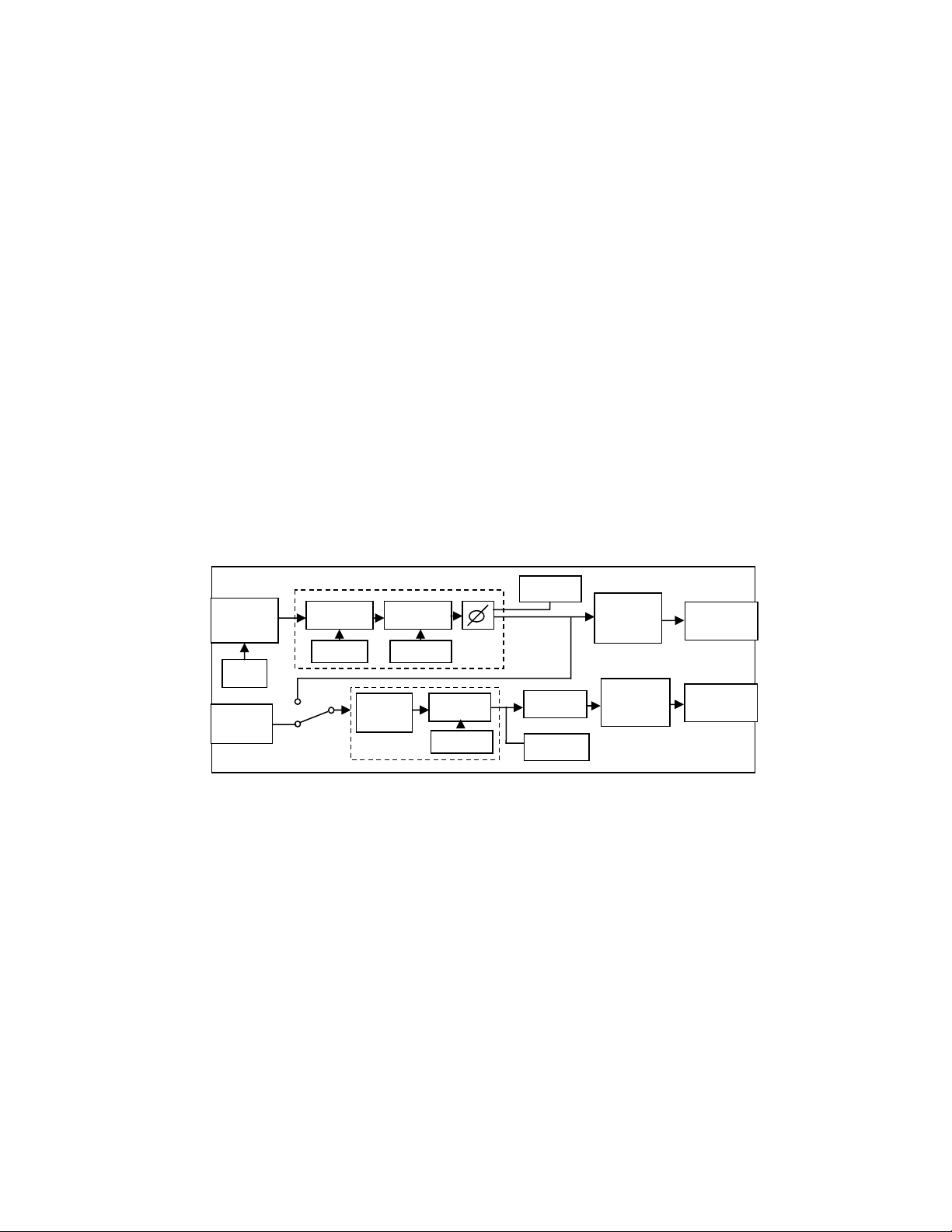
2.2 The Signal flow of one channel is shown below. Note
that the gain trim is in front of the EQ modules, and that
the output meter tap is before the fader. These facts are
important for proper operation of the MPE-200.
MIC IN
XLR
+48
EQ IN
XLR
PREAMP FILTERS
GAIN
TRIM
IN SEL.
Signal Flow of an MPE Channel
BYPASS
EQ (4)
BYPASS
METER
FADER
METER
XFMR
OUTPUT
STAGE
XFMR
OUTPUT
STAGE
MIC OUT
XLR
EQ OUT
XLR
Page 7

MPE-200 Guide to Operations Page 7
SYSTEM OVERVIEW (ctd)
2.2 The MPE-200 has six control modules which are labeled on
the front panel. The outer two modules control Input
functions (mic gain, HP/LP filters, and setup) on the left, and
Master functions (gain trim, presets, setup and fader) on the
right. The four remaining modules control each of the four
equalizer bands, which are post mic preamp. The EQ may be
used separately from the mic preamps which have their own
outputs.
2.3 The MPE-200 uses two types of controls: Displays Switches
and Encoders. In general, pressing the display switch changes
the screen to a new mode. Turning the encoder changes the
parameter, and pressing the encoder knob selects the
parameter associated with that encoder. The display screen
backlight color is used to convey status for each module, but
this information is also contained in the screen contents, to
accommodate users whose color perception is impaired.
Page 8

Page 8 MPE-200 Guide to Operations
2.4 CHANNEL STATUS
Channel status is displayed by a lock icon, showing both
unlocked or locked status, as well as channel and EQ
selection.
Channel selected or EQ on, preset unlocked
Channel selected or EQ on, preset locked
Channel unselected or EQ off, preset unlocked
Channels unselected or EQ off, preset locked
These icons also show what is being controlled by the
associated encoder(s). When a preset is unlocked, all changes
made to that preset will automatically be saved. If the preset is
locked, settings can still be changed and the changes will affect the
audio path, but these changes will be lost when another preset is
loaded or the MPE-200 is turned off.
Preset Memory
Control changes
and
Control Flow
Working
Memory
Load preset
Audio Signal Control
NOTE: A special situation occurs when recalling a preset on a single chann el
that has the same number as the preset on the other channel. In this instance, the
new preset will acquire the settings of the other channel, even if the new preset
is locked. For example, say Channel A has preset 1 loaded and it is locked, and
channel B has preset 2 loaded. Changes are made to channel A. If preset 1 is
now recalled on channel B, the changes made on channel A will also be applied
to channel B, even though these changes have not been stored in preset 1 (which
is locked). See section 5.3 to learn more about how presets work.
Locked?
No Yes
Preset
memory
Don’t Save
Page 9

MPE-200 Guide to Operations Page 9
3. INPUT SCREENS
The input controls are located on the far left of the MPE-200. Press
the Display Switch to select the Mic Gain, Filter, or Setup screens;
press the Encoder Knob until the desired item flashes and rotate
the knob to modify the selected item.
3.1 MIC GAIN screen (green).
Chan A gain
9 dB
5 dB
………..:..
• The Mic Gain control can apply to either or both channels. The
lock icons show which gain(s) are currently being controlled.
Pushing the knob selects chan A, chan B, or both channels.
Gain offsets can be obtained be selecting each channel
individually and selecting a gain amount, then selecting both
channels. This operation emulates a clutched stereo analog
control in that the offset is removed if both channels are set to
minimum or maximum gain.
• The Mic Gain control is always in fine mode, or one dB per
click. Note that even in Master stereo mode, individual mic
gain adjustments are possible, and both mic gains are stored in
a single preset when used for stereo operation.
• The Mic peak indicator triggers at +20 dBu (entire screen
changes to red), or 3 dB before clipping begins. The meter
indicates a ranges of –43 dBu to +15 dBu, with a reference
level marker at 0 dBu. The A channel level is shown by the
upper meter bar.
Chan B gain
Chan A level
Chan B level
Mic gain for Channel B selected,
preset for Channel B locked
Page 10

Page 10 MPE-200 Guide to Operations
3.2 HP/LP FILTER screen (amber).
[*]
20 30
Hz kHz
This screen controls the two 12 dB/octave filter sections of the
MPE Mic Preamps. Each filter can be highpass or lowpass, and if
both are set to the same frequency, the resulting slope is 24
dB/octave. Push the knob to select either filter. Rotate the knob to
select the desired frequency, or an off position. When off, these
filters are completely removed from the signal path.
The filter settings shown are applied to the active
channels(s) determined by the Master channel selector
(see section 5.1), not the channel(s) selected on the mic
gain screen.
Highpass filter at 20 Hz and
lowpass filter at 30 kHz selected
Page 11

MPE-200 Guide to Operations Page 11
3.3 INPUT SETUP screen (yellow).
48
+ Ph -
Mic In
This screen controls 48v. phantom power on or off for each
channel; phase + or – for each channel; Mic or Eq input to both Eq
channels. Push the knob to select the desired function; rotate the
knob to modify the setting.
• An open circle indicates +48v is off; a filled circle is +48v on.
• The minus sign (-) means the Mic Pre phase is inverted.
• The input selection (Mic or Eq) selects what is feeding the Eq.
The input selection and phase are retained if the power is cycled,
but the phantom power settings are not saved and default to off as
a safety feature.
When Mic In is selected, the output of each preamp is routed to
the corresponding Eq input; if Eq In is selected, the inputs on the
back of the MPE are routed to the Eq. Both channels are switched
together. The direct outputs of the Mic preamps are always live.
This allows the MPE-200’s preamps and Eq's to be used
separately. If Eq In is selected, you can also insert external
equipment such as compressors between the Mic Pre outputs and
Eq inputs of the MPE.
Chan A phantom power on
Chan B phase inverted 180°
Mic preamp selected to feed EQ input
Page 12

Page 12 MPE-200 Guide to Operations
4. EQUALIZER SECTION
2
+9.5
35 Hz
4.1 EQUALIZER OVERVIEW
The MPE-200 has four bands of Eq, each of which can be selected
either ON (green) or OFF (amber) by pressing each display. The
on/off state of each Eq band is also shown by the lock icons on its
display. A lock icon on the left of the display refers to the “A”
channel, with the state of the “B” channel shown on the right. When
off, the filter circuit is completely removed from the signal path.
4.2 BOOST / CUT CONTROL
The Eq Boost/Cut control is to the right of each filter display. The
range is ±16 dB, in coarse (2 dB) steps or fine (0.5 dB) steps.
Pressing the encoder knob switches between coarse and fine control,
and the LEDs below the knob show the current control mode.
4.3 FREQUENCY CONTROL
Frequencies are selected by rotating the encoder knob below each
Eq display. For High and Low Eq, peaking or shelving can be
selected by pressing the frequency knob. In either case, the filter
slope is fixed at 12 dB/octave.
Channel B LF filter off (amber), set for shelving,
preset unlocked, with 9.5 dB added at 35 Hz
Page 13

MPE-200 Guide to Operations Page 13
4. EQUALIZER SECTION (ctd)
1
+16.0
100 Hz
4.5 Q CONTROL
Low-mid and High-mid EQ sections are parametric peaking filters.
Filter Q adjustment is accessed by pressing the frequency encoder
knob. The range of adjustment is 0.6 (1.6 octave) to 2.0 (0.5
octave). A higher Q number represents a sharper or narrower
bandwidth filter. The encoder scale always shows frequency, even
when Q is being adjusted.
1
+16.0
q 1.2
+20
+10
d
+0
B
u
-10
Channel A peaking Eq on (green), preset
locked, 16 dB gain applied at 100 Hz
The same filter settings, showing the
Q, or bandwidth adjustment
-20
20 40k 50 100 200 500 1k 2k 5k 10k 20k
Page 14

Page 14 MPE-200 Guide to Operations
5. MASTER SCREENS
Press the Master LCD Display Switch on the far right side of the
MPE-200 to select Gain Trim, Preset, Setup, or Fader screen.
Channel A selected, preset locked, stereo operation
with 8.5 dB cut applied.
Channel A Eq In level
Channel B Eq In level
the EQ modules. If
[*]
Ch 1S
-8.5
………:…
5.1 MASTER CHANNEL SELECT
If the MPE-200 is in 2-channel mode, pressing the knob selects
the channel select icon (it will start blinking). Turn the knob to
switch the control of gain trim, all Eq modules, and the Mic
filters between channel A and channel B. All the displays
change to show the settings of the selected channel. If Stereo
mode is set, both channels are controlled at once (“S” will
appear behind the channel number).
If both channels have the same preset number loaded, the MPE200 behaves as if in stereo mode. Set each channel to a different
preset for 2-channel mode. See section 5.3 for details concerning
presets.
The EQ Output Meter and peak displays are also on this screen,
with the meter reference line at 0 dBu, and a peak indicator level of
+18 dBu which flashes red when 3 dBu below clipping.
5.2 EQ GAIN TRIM
Turning the encoder sets gain of ±16 dB for each channel. The
adjustment occurs in the signal path before
there is a substantial amount of EQ boost, reduce the EQ gain to
prevent overload of the EQ circuits. Conversely, if there is much
EQ cutting, add some positive trim to maintain output level.
Page 15

MPE-200 Guide to Operations Page 15
5.3 MASTER PRESET screen (amber)
4 6
↑ 25
1 8
There are 25 user presets which store all settings and controls
except input setup and the output fader. Each channel has a preset,
whose number is shown on the top row of the Preset screen, along
with the lock status. Select a preset by turning the knob, and load it
by pressing the knob. A flashing arrow will always show the
pending preset selection.
If the preset selected is the same number as the current preset, the
pending preset number changes to the last previously loaded one.
Thus, by repeatedly pressing the knob, you can alternate between
any two presets, for “A-B” comparison.
If the MPE-200 is set to Stereo mode, a single preset is loaded
simultaneously for both channels, as shown on the preset page.
You can also manually select the same preset for both channels
while the MPE-200 is in 2-channel mode. In this state, all the
controls will operate as if in stereo mode, but changing presets is a
bit cumbersome. When changing from Stereo mode to 2-channel
mode, the MPE-200 will enter this state.
Any changes made to the settings while an unlocked
[*]
See the next section for details on locking and unlocking presets.
preset is selected will be automatically stored. Any
changes made to a locked preset will be lost when another
preset is loaded or when the MPE-200 is turned off.
Channel B is the active channel, preset 6 selected
and unlocked, with preset 25 waiting to be loaded;
preset 8 is the previous preset for Channel B.
Page 16

Page 16 MPE-200 Guide to Operations
5.4 MASTER SETUP screen (yellow).
2-Chan
NoFade
Master Setup functions include preset locking, channel mode, and
fader enable. Press the encoder knob to select the desired function
and turn the knob to change the parameter.
Preset Locking
To lock and unlock presets, turn the encoder knob while the lock
icon is blinking. Press the encoder knob to select either channel. If
Stereo mode is selected or if presets A and B are identical, both
lock icons will be selected.
When a preset is changed from locked to unlocked, changes made
while it was locked will NOT be stored; only changes made while
the preset is unlocked will be stored in the preset memory.
Channel Mode
The channel mode controls the basic configuration of the MPE-
200. When set to Stereo, all the Eq controls operate equally on
both channels. The Mic gains can still be set separately, but both
gains are part of a single preset. See Section 3.1 for details. When
the channel mode is set to 2-Chan, each of the A and B channels
has its own Eq and gain settings, stored in separate presets.
To adjust the channel mode, turn the encoder knob while the
Stereo / 2-Chan icon is blinking. When changing from 2-Chan to
Stereo mode, channel B inherits the current settings of channel A,
even if either or both presets are locked.
The channel mode is not part of the preset memory and is not
affected by the lock state, but is saved when power is turned off.
Presets A and B unlocked
2 channel mode selected,
Fader disabled
Page 17

MPE-200 Guide to Operations Page 17
MASTER SETUP (ctd)
Fader Enable
The last item of the Master Setup screen enables the Fader screen.
If set to No Fade, the Fader Screen is bypassed, and the Fader
attenuator is set fully on (0 dB). Push the knob until No Fade/Fader
is blinking, and turn the knob to enable or disable the Fader page.
5.5 OUTPUT FADER screen (dark green).
Fade
-39
-
The output fader approximates a standard fader curve, with –20 dB
occuring at mid-scale. The fader is always in fine mode, with 64
steps covering the full range.
The precision attenuator is after the meter and peak
[*]
sensing in the signal path, so it should always be set to
“0” unless doing a fade.
Fader screen
Channel A has 39 dB of attenuation
Channel B has 72 dB of attentuation
Both channels are enabled for Fade
Pressing the knob selects either or both channels to fade. Each
channel can be controlled separately, even if the Master channel
mode is Stereo, and any offset is retained when switching back to
stereo fade. Settings are not stored and will be discarded when the
fader is disabled, or when a new preset loaded.
Page 18

Page 18 MPE-200 Guide to Operations
6. MIDI
The Musical Instrument Digital Interface is an industry-wide standard
system for conveying musical and audio control data between devices
of many types, including keyboards, samplers, signal processors, and
audio mixers. Standard MIDI cables are available at most music stores.
The MPE-200 has three standard rear panel MIDI connectors:
• MIDI IN receives data into the MPE-200 from other devices such
as computer sequencers, suitably equipped mixers and controllers,
or another MPE.
• MIDI OUT sends data from the MPE-200 to compatible devices.
• MIDI THRU sends out an exact copy of the signal at the
jack. Think of it as a built-in 'Y' connector.
MIDI
ID
MIDI channel 1 selected
1
Every time a preset is loaded, a SysEx message containing the preset
just loaded is sent to the MIDI output. This SysEx message can be
recorded on a SysEx librarian or sequencer, to store the preset data.
You can also connect two MPE's directly together by MIDI.
In all cases, the receiving MPE must have the preset page selected, and
the preset must be unlocked. The received data will be stored into the
currently selected preset location, not the one corresponding to that of
the sending unit.
Turning any encoder or pressing any LCD display sends MIDI
continuous controler messages (CC commands) through the MIDI
output, which can be recorded in a MIDI sequencer. Send these
messages back into the MIDI input for full automation of all
parameters of the MPE-200.
The MIDI connectors are also necessary for use with the Extension 78
TDM plug-in for Digidesign’s ProTools digital audio workstations.
MIDI ID select page on input LCD
MIDI in
Page 19

MPE-200 Guide to Operations Page 19
7. SLEEP MODE
The MPE-200 can be turned off from the front panel by pressing and
holding the Master display, then with the Master screen held, press the
Input display for one second. This turns off the analog power and
displays a flashing green beacon as a reminder that the MPE-200 is
only sleeping. To wake it up, press the Input display for ½ second.
This unit can also be put to sleep by pressing and holding the input
encoder, pressing the input LCD, releasing the encoder, and holding
the input LCD until the unit turns off. This is great for one-handed
operation, and for turning off slave units (MPE-200S, EQ-200S).
Page 20

Page 20 MPE-200 Guide to Operations
8. FUSE AND VOLTAGE SELECTION
The main fuse and the voltage selector are part of the Power Entry
module on the rear panel of the MPE-200, where the power cord
connects. The fuse will only fail if there is a circuit fault. If the
MPE shuts down unexpectedly, or fails to turn on, first confirm
that it is connected to a source of the correct voltage.
!
!
!
8.1 FUSE INSPECTION OR REPLACEMENT
Remove the rectangular fuse holder by gently prying at the notch
provided with a small screwdriver or paper clip. Use only slowblow 5x20 mm. fuses of these types and values:
!
!
!
The fuse should only fail if there is an internal circuit fault in the
MPE-200. If you find a blown fuse, please contact Summit Audio
Customer Service before attempting replacement.
CAUTION: Disconnect the power cord from the MPE
before attempting fuse inspection or voltage selection!
ATTENTION:
FUSIBLE.
For 90-125 volt, use two 0.8 amp fuses type IEC 127-2
For 200-250 volt, use two 0.4 amp fuses type IEC 127-2
UTILISER UN FUSUBLE DE RECHANGE DE MEME TYPE DE
0.8A - 90-125v, 0.4A - 200-250v.
DEBRANCHER AVANT DE REMPLACER LE
ATTENTION:
Page 21

MPE-200 Guide to Operations Page 21
8.2 VOLTAGE SELECTION
Changing the supply voltage requires some
mechanical dexterity. If you have any doubt
about your mechanical abilities, please contact
your Summit dealer for assistance.
1) Using a long-nose pliers, gently pull the voltage selector
tab out of the right end of the Power Entry module.
2) Carefully move the white plastic key around the side of the
selector tab, until it faces AWAY from the desired voltage
legend printed on the tab.
3) Push the plastic key gently into the locating notch in the
edge of the tab. Double check that the voltage printed on
the edge of the tab away from the key is the one you want.
4) Carefully insert the selector tab back into the slot at the
right side of the Power Entry module, with the white plastic
key facing away from the MPE and the printed voltage
legend on the side of the tab toward the fuse holder. Firmly
push the tab into the slot until it seats.
5) Install the correct value fuse for the voltage you have
chosen. See section 8.1 for these values. Replace the fuse
holder and gently press it until it clicks.
6) Inspect the white dot which shows through the fuse holder
and confirm that the voltage setting is what you want.
9. REGISTRATION
Thank you for purchasing the MPE-200. Please fill out and return
the enclosed warranty card. When you register the unit, Summit
Audio will better be able to notify you of manual, firmware, and
MIDI upgrades. This unit must be registered for the extended three
year warranty to be in effect.
Please do not hesitate to phone, fax or e-mail Summit Audio with
any questions or comments. Many thanks from the Element 78
group of Summit Audio.
Page 22

Page 22 MPE-200 Guide to Operations
The MPE-200 is designed and manufactured in the USA by
Summit Audio, Inc.
1183 Baltic Suite A
Gardnerville, NV 89410 USA
TEL 775-782-8838
email: sound@summitaudio.com
Contents of this manual are Copyright ©1999/2000
by Summit Audio, Inc. All Rights Reserved
Summit document 1044C01
 Loading...