

Summit VV40H, VV40HL, VV40AK, VV40L, VV40KK Installation, Operation & Maintenance Manual
...Page 1
SUMMIT PUMP MODEL SPL PROGRESSIVE CAVITY i
Page 2

INSTALLATION, OPERATION, AND MAINTENANCE MANUAL
ii SUMMIT PUMP MODEL VV40 INTERNAL GEAR PUMP
Page 3

INSTALLATION, OPERATION AND MAINTENANCE MANUAL
i. WARRANTY
Pumping units assembled by Summit Pump, Inc., Green Bay, WI are guaranteed to be free from defects in
material and workmanship for one year from date of shipment from factory in Green Bay, WI. The
obligation under this warranty, statutory or otherwise, is limited to replacement or repair at Green Bay, WI,
of such part as shall appear to us upon inspection at such point, to have been defective in material or
workmanship.
This warranty does not obligate Summit Pump, Inc. to bear the cost of labor or transportation charges in
connection with replacement or repair of defective parts; nor shall it apply to a pump upon which repairs or
alterations have been made unless authorized by Summit Pump, Inc.
No warranty is made in respect to engines, motors, or trade accessories, such being subject to warranties of
their respective manufacturers.
No express implied or statutory warranty, other than herein set forth is made or authorized to be made by
Summit Pump, Inc.
In no event shall Summit Pump, Inc. be liable for consequential damages or contingent liabilities arising out
of the failure of any Summit Pump, Inc. pump or parts thereof to operate properly.
ii. LIABILITY
Summit Pump, Inc. shall not be liable for personal physical injury, damage or delays caused by failure to
follow the instructions and procedures for installation, operation and maintenance contained in this manual.
The equipment is not for use in or with any nuclear facility or fire sprinkler system. Buyer accepts the
responsibility for insuring that the equipment is not used in violation and Buyer shall indemnify and hold
Seller harmless from any and all liability (including such liability resulting from seller’s negligence) arising
out of said improper use.
iii. COPYRIGHT
This Installation, Operation, and Maintenance Manual contains proprietary information, which is protected
by copyright. No part of this Installation, Operation, and Maintenance Manual may be photocopied or
reproduced without prior written consent from Summit Pump.
The information contained herein is for informational use only and is subject to change without notice.
Summit Pump assumes no responsibility or liability for any errors or inaccuracies that may appear in this
manual.
SUMMIT PUMP MODEL VV40 INTERNAL GEAR PUMP iii
Page 4

INSTALLATION, OPERATION, AND MAINTENANCE MANUAL
iv SUMMIT PUMP MODEL VV40 INTERNAL GEAR PUMP
Page 5

INSTALLATION, OPERATION AND MAINTENANCE MANUAL
1 CONTENTS
I. WARRANTY .............................................. III
II. LIABILITY .................................................. III
III. COPYRIGHT .............................................. III
1 CONTENTS ............................. V
2 INTRODUCTION ..................... 1
7.2.3 Grease ............................................ 15
7.3 PACKING ................................................ 15
7.3.1 Packing Adjustment ....................... 16
7.3.2 Packing Lubrication ........................ 16
7.4 MECHANICAL SEALS .............................. 17
7.5 FIRST RUN CHECK .................................. 17
7.5.1 Start Up .......................................... 17
7.5.2 Shut Down ...................................... 18
3 SAFETY .................................. 2
3.1 PUMP SAFETY WARNINGS ....................... 2
4 NOMENCLATURE ................... 4
4.1.1 Model Size ........................................ 4
4.1.2 Seal Type & Material ........................ 4
4.1.3 Materials of Construction ................. 4
4.1.4 Additional Items ............................... 5
4.1.5 Special to Application ....................... 5
5 RECEIPT AND STORAGE ......... 7
5.1 RECEIVING THE PUMP .............................. 7
5.2 STORING THE PUMP ................................ 7
5.2.1 Temporary ........................................ 7
5.2.2 Long Term ......................................... 7
5.3 HANDLING ............................................... 7
5.4 LIFTING .................................................... 7
6 INSTALLATION ....................... 8
6.1 GENERAL .................................................. 8
6.2 LOCATION ................................................ 8
6.3 BASE PLATE .............................................. 8
6.4 FOUNDATION .......................................... 8
6.4.1 Concrete Sub-Base ........................... 8
6.5 BASE PLATE GROUTING............................ 9
6.6 ORIENTATION AND ROTATION .............. 11
6.6.1 Casing Orientation .......................... 12
6.7 PIPING CONNECTION – SUCTION /
DISCHARGE ............................................ 12
6.7.1 Suction Piping ................................. 12
6.7.2 Discharge Piping ............................. 12
6.8 ALIGNMENT ........................................... 13
6.8.1 Coupling Connected Units .............. 13
6.8.2 Belt Driven Units ............................. 13
6.8.3 Alignment Checks ........................... 13
7 OPERATION ......................... 14
7.1 CHECKING ROTATION ............................ 14
7.2 LUBRICATION ......................................... 14
7.2.1 Packing ........................................... 14
7.2.2 Bearings .......................................... 15
8 MAINTENANCE TIMETABLE . 19
8.1 DAILY MAINTENANCE ............................ 19
8.2 THREE MONTH MAINTENANCE ............. 19
8.3 SIX MONTH MAINTENANCE ................... 19
8.4 YEARLY MAINTENANCE ......................... 19
9 TROUBLESHOOTING ............ 20
9.1 PUMP PROBLEMS .................................. 20
9.2 PROBABLE CAUSE AND REMEDY. ........... 20
10 EXPLODED VIEWS ............... 21
10.1 VV40H & VV40HL CAST IRON.................... 21
10.2 VV40H & VV40HL STAINLESS STEEL ............ 22
10.3 VV40H & VV40HL CAST IRON & STAINLESS
STEEL – BEHIND ROTOR MECHANICAL SEAL .... 23
10.4 VV40L, LL, LQ & LS CAST IRON & STAINLESS
STEEL ....................................................... 24
11 DISASSEMBLY MODEL VV40 25
11.1 HEAD AND CASING ................................ 26
11.2 BEARING HOUSING ................................ 26
11.3 REMOVING SEALS .................................. 27
11.3.1 Packing ........................................... 27
11.3.2 Component Mechanical Seal.......... 27
11.4 BRACKET AND CASING ........................... 28
11.5 INTERNAL RELIEF VALVE ........................ 28
12 ASSEMBLY MODEL VV40 ..... 29
12.1 BRACKET & IDLER BUSHINGS ................. 29
12.1.1 Normal installation ......................... 30
12.1.2 Heated installation ......................... 30
12.1.3 Bushing Temperature Limits .......... 31
12.2 BRACKET AND CASING ........................... 31
12.3 INSTALLING SEALS ................................. 31
12.3.1 Packing ........................................... 32
12.3.2 Component Mechanical Seal.......... 32
12.4 BEARING HOUSING ................................ 33
12.5 HEAD AND CASING ................................ 34
12.6 ADJUSTING END CLEARANCE ................. 35
12.6.1 Measured Rotation Method .......... 35
12.6.2 Dial Indicator Method .................... 36
SUMMIT PUMP MODEL VV40 INTERNAL GEAR PUMP v
Page 6

INSTALLATION, OPERATION, AND MAINTENANCE MANUAL
12.7 INTERNAL RELIEF VALVE ......................... 38
12.7.1 Mounting valve on head ................. 38
12.7.2 Setting pressure .............................. 38
13 APPENDIX E – REFERENCE
TABLES ................................ 40
13.1 TORQUE GUIDELINES ............................. 40
13.1.1 Bolt Torques .................................. 40
13.1.2 Locknut Torques ............................. 40
14 PUMP INFORMATION .......... 41
ii SUMMIT PUMP MODEL VV40 INTERNAL GEAR PUMP
Page 7
INSTALLATION, OPERATION, AND MAINTENANCE MANUAL
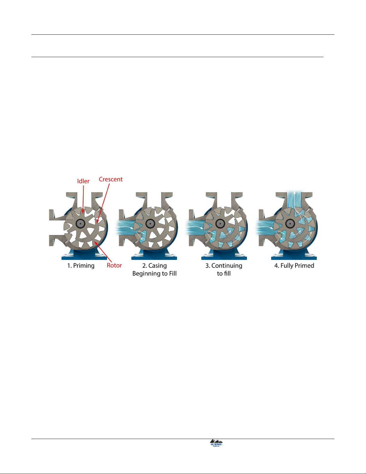
Figure 2-1: Priming cycle and gear pump design principle
2 INTRODUCTION
This installation, operation, and maintenance manual is designed to help you achieve the best performance
and longest life from your Summit Pump.
This pump is a positive displacement internal gear type. The pump’s drive shaft turns a ring gear (rotor), with
internal teeth, which rotates the external gear (idler). The idler rotates on a pin and meshes its external teeth
with the rotor’s internal teeth.
The crescent is integrated with the pump head and spaced between the internal teeth and external teeth. As
the gear teeth disengage at the intake port, liquid enters and is trapped in the space of each gear tooth. The
liquid is carried to the discharge port. The meshing of the two gears and the space reduction, forces the liquid
from the pump through the discharge port. Figure 2-1 below illustrates the internal gear pump design
principle.
If
there are any questions regarding this pump or its application, which are not covered in this manual, please
contact your local Summit Pump, Inc. Distributor.
For information or technical assistance on the driver service, contact the driver manufacturer’s local dealer or
representative.
SUMMIT PUMP MODEL VV40 INTERNAL GEAR PUMP 1
Page 8
INSTALLATION, OPERATION, AND MAINTENANCE MANUAL
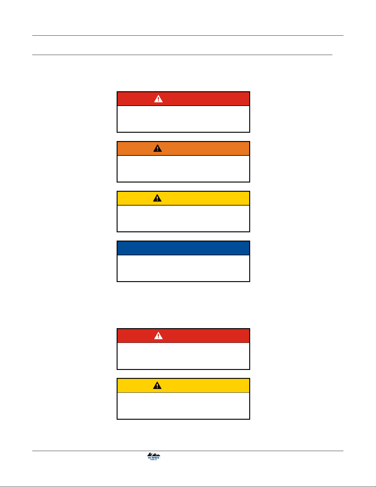
3 SAFETY
The following message types are used in this manual to alert maintenance personnel to procedures that
require special attention for the protection and safety of both personnel and equipment:
DANGER
Imminently hazardous situation which, if not
avoided, will result in death or serious
injury.
WARNING
Potentially hazardous situation which, if not
avoided, could result in death or serious
injury.
CAUTION
Potentially hazardous situation which, if not
avoided, may result in minor or moderate
injury.
NOTICE
Includes Information on operation,
maintenance, rules or directions. May
indicate possible property damage.
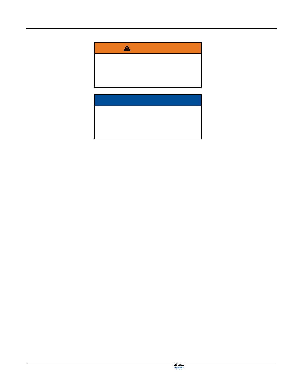
3.1 PUMP SAFETY WARNINGS
The safety information below should be followed and observed to prevent damage to equipment or injury to
operators:
DANGER
Ensure discharge line is open and free of
clogs before operation. Negligent acts may
result in serious injury or death.
CAUTION
Feeding very hot or very cold fluid into the
pump at room temperature may result in
fracture of pump wet end.
2 SUMMIT PUMP MODEL VV40 INTERNAL GEAR PUMP
Page 9
INSTALLATION, OPERATION, AND MAINTENANCE MANUAL
WARNING
Follow all auxiliary equipment (motors,
drives, couplings etc.) manufacturer’s
manuals, instructions or procedures during
installation, operation and maintenance of
the pump.
NOTICE
Check all end clearances, drive to shaft
alignments, fastener torques, equipment
lubrication, gaskets and seals for leaks and
all equipment is fastened into place before
operation.
SUMMIT PUMP MODEL VV40 INTERNAL GEAR PUMP 3
Page 10

INSTALLATION, OPERATION, AND MAINTENANCE MANUAL
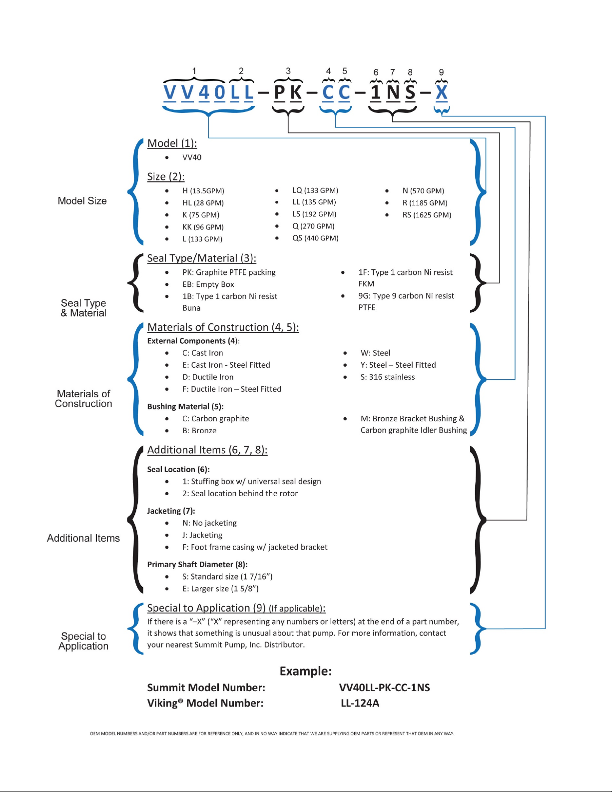
4 NOMENCLATURE
On page 41 of this manual, record the nameplate data from your pump. This will assist with any maintenance
questions or pump identification in the future.
As where “sections” are stated in section 4, NOMENCLATURE, refer to Page 6 for clarification.
Summit internal gear pumps are essentially identified by Model Size (sections 1 & 2, i.e. VV40LL). The
remaining format consists of the Seal Type & Material (section 3, i.e. “PK”), Materials of Construction
(sections 4 & 5, i.e. “CC”), Additional Items (sections 6, 7 & 8, i.e. “1NS”), and finally Special to
Application (section 9, if applicable, i.e. “X”). These items together represent the complete identification of
the pump and should be stated when ordering repair parts.
4.1.1 Model Size
(“VV40LL”, Sections 1 & 2) The format consists of the pump model (section 1) and the pump size (section
2).
Section 1 specifies a specific group or style of gear pump. This value changes when the style of gear pump is
altered. For this manual section 1 is “VV40”.
Section 2 identifies a specific pump size within the gear pump model. Sizes are justified via the capacity
(GPM) of the pump. (i.e. “LL”)
4.1.2 Seal Type & Material
(“PK”, Section 3) Section 3 identifies how the pump is sealed and with what materials. Options are packing,
type 1 or type 9 component mechanical seals, or a cartridge mechanical seal.
4.1.3 Materials of Construction
(“CC”, Sections 4 & 5) Section 4 identifies the materials of the working internals and cast parts of the pump.
Each letter represents a relationship with these components. See Figure 4-1 for specific item materials of
construction.
Section 5 identifies the type of bushing used in the bracket and idler. Options are either carbon graphite or
bronze.
4 SUMMIT PUMP MODEL VV40 INTERNAL GEAR PUMP
Page 11
INSTALLATION, OPERATION, AND MAINTENANCE MANUAL
(C) CAST IRON (D) DUCTILE IRON (W) STEEL (S) STAINLESS STEEL
CAST I RON DUCTILE IRON STEEL STAINLESS STEEL
CAST I RON DUCTILE IRON STEEL
STAINLESS STEEL
CAST I RON STEEL STEEL CAST I RON
CAST I RON DUCTILE IRON STEEL STAINLESS STEEL
*CAST I RON *CAST I RON *CAST I RON
STAINLESS STEEL
STANDARD
MATERIAL
**CAS T IRON **CAS T IRON **CAS T IRON
STEEL
CONSTRUC TION
STEEL
("E" in NOMENCLATURE)
STEEL
("F" in NOMENCLATURE)
STEEL
("Y" in NOMENCLATURE)
STEEL STEEL STEEL STAINLESS STEEL
HARDENED STEEL HARDENED STEEL HARDENED STEEL
HARD COATED
STAINLESS STEEL
PACKED BRONZE BRONZE BRONZE
MECHANIC AL
SEAL
^ CARB ON GRAPHITE ^ CARB ON GRAPHITE ^ CARB ON GRAPHITE
CAST I RON STEEL STEEL
STAINLESS STEEL
* STEEL FOR Q AND QS STEEL FITTED OPTION. H AND HL ARE POWERED METAL
** KK, LS, QS HAVE DUCTILE IRON ROTOR
^ BEHIND ROTOR SEAL: ALL BUSHINGS ARE BRONZE EXCEPT SIZES H TO KK HAVE CARBON GRAPHITE IDLER BUSHINGS
INTER NAL PRESSURE RELI EF VALVE (4 7)
SECTION "4" EXTERNAL COMPONENTS IN NOMENCLATURE
ITE M (ITEM NUMB ER)
STAINLESS STEEL
^ CARB ON GRAPHITE
MODEL VV40 MATERIALS OF CONSTRUCTION
ROTOR (3 6)
IDLER BUSHING (38)
& B RACKET B USHIN G (25 )
CASING (31)
HEAD (40)
JAC KET HEAD PLATE (4 2)
BRAC KET (27 )
IDLER (37)
SHAF T (36)
IDLER PIN (39)
4.1.4 Additional Items
(“1NS”, Sections 6, 7 & 8) These sections define additional information about the options of the pump.
Section 6 identifies the sealing location, either behind the rotor or in the stuffing box.
Section 7 identifies the type of bracket and casing. There is an option to jacket these parts to induce a heat
exchanger for high temp applications.
Section 8 identifies the standard or larger shaft diameter.
4.1.5 Special to Application
(“X”, Section 9) Section 9 may or may not be present. Usually, there will be no “X” following the pump
identification. If there is an “X”, you will need to contact your nearest Summit Pump, Inc. Distributor to
determine exactly what makes this pump special.
See following page for nomenclature definitions and examples
SUMMIT PUMP MODEL VV40 INTERNAL GEAR PUMP 5
Page 12
INSTALLATION, OPERATION, AND MAINTENANCE MANUAL
Figure 4-1: Materials of Construction; Reference Summit Pump VV40 nomenclature
6 SUMMIT PUMP MODEL VV40 INTERNAL GEAR PUMP
Page 13
INSTALLATION, OPERATION, AND MAINTENANCE MANUAL
5 RECEIPT AND STORAGE
5.1 RECEIVING THE PUMP
Immediately upon arrival, carefully inspect the pump for evidence of damage during transit. Immediately
report any damage to your local Summit Pump, Inc. Distributor.
5.2 STORING THE PUMP
5.2.1 Temporary
Temporary storage: less than six months.
1. Flush the pump with clean water. If pumped product is water reactive, remove the pump head, and
with compressed air blow all liquid from cavity. Lightly cover all internal metal parts with oil and
replace the head.
2. Store pump in a clean, dry place, free from extreme swings in temperature and humidity.
3. Cover with a protective covering to reduce dust contamination.
4. Loosen the packing gland nuts; remove the gland, packing rings and lantern ring. Apply grease to the
stuffing box I.D. and packing rings. Return the packing and lantern rings to their position in the
stuffing box. Snug down the packing gland nuts finger tight. Do not use grease if gland is water
flushed. Only a small amount of light oil should be applied in this scenario.
5. Rotate the shaft once a week to protect the bearings from being indented into the raceway.
5.2.2 Long Term
Long Term Storage: more than six months.
1. Follow temporary storage guidelines 1-5.
2. Coat all unpainted and machined surfaces with a rust inhibitor, such as LPS-3.
5.3 HANDLING
Pump unit boxes and crates may be unloaded using a forklift or slings depending on size and package
construction.
WARNING
Pump and assemblies are heavy, improper
handling could result in serious injury.
5.4 LIFTING
To avoid damage to pump and/or motor use a nylon, chain, or a wire rope sling. The slings should be placed
so lift is equally supported at four or more points.
Be sure all components are securely
fastened to baseplate before lifting.
WARNING
SUMMIT PUMP MODEL VV40 INTERNAL GEAR PUMP 7
Page 14

INSTALLATION, OPERATION, AND MAINTENANCE MANUAL
6 INSTALLATION
6.1 GENERAL
Summit Pumps are fully assembled at the factory. The pumps are ready to be installed and put into service.
Follow all instruction tags on the pump.
6.2 LOCATION
If the pump is going to have a water flush, it should be located as close as possible to the supply of water.
Other location considerations are: easy access for inspection, maintenance and ample overhead space for
lifting with crane or hoist.
6.3 BASE PLATE
Each pump unit should be mounted on a fabricated steel base plate. Common base configurations are inline,
piggyback and L-shape. The base plate should be mounted on a concrete sub base 4” to 8” longer and wider
than the fabricated base plate.
6.4 FOUNDATION
6.4.1 Concrete Sub-Base
The concrete sub foundation performs a number of functions. It must support the weight of the entire pump
assembly, maintain the alignment of all system components, and absorb the loads, forces and vibrations that
are developed under normal operating conditions. The concrete material used must be top quality and
conform to local building codes as well as the contractor’s strength requirements. Reinforcing bars and mesh
should be used as required. The mounting surface of the concrete foundation must be flat and level beneath
the footprint of the sub-base, or the pump could be installed out of square. This could create problems
aligning the piping, place extra loads on the couplings and bearings, and alter the operating levels of
lubricants or hydraulic fluids in the system. It is recommended that the top surface of the slab be held flat and
level to at least F50 according to American Concrete Institute (#117) and the Canadian Standards
Association (#A23.1) which is approximately 1/8” per 10 foot. The sub base height is usually determined by
the process piping runs and elevation.
The weight of the sub foundation should be 3-5 times the weight of the pump, motor and baseplate.
Dimensionally, it should be 4” to 8” longer and wider than the polymer concrete or fabricated steel base
plate. Anchor bolts are installed in pipe sleeves. The pipe diameter is 2.5 times larger than the anchor bolt
diameter. This sleeve/bolt assembly is embedded in the base when poured.
The pipe sleeve should be filled with sand or plastic foam to the top of the sleeve. This will prevent the grout
material from spilling into the sleeve and reducing the movement of the sleeve when pouring the grout.
Anchor bolt sizes: 1”-8UNC. Length is 7.5” to 10”, depending on base thickness and overall size.
8 SUMMIT PUMP MODEL VV40 INTERNAL GEAR PUMP
Page 15
INSTALLATION, OPERATION, AND MAINTENANCE MANUAL
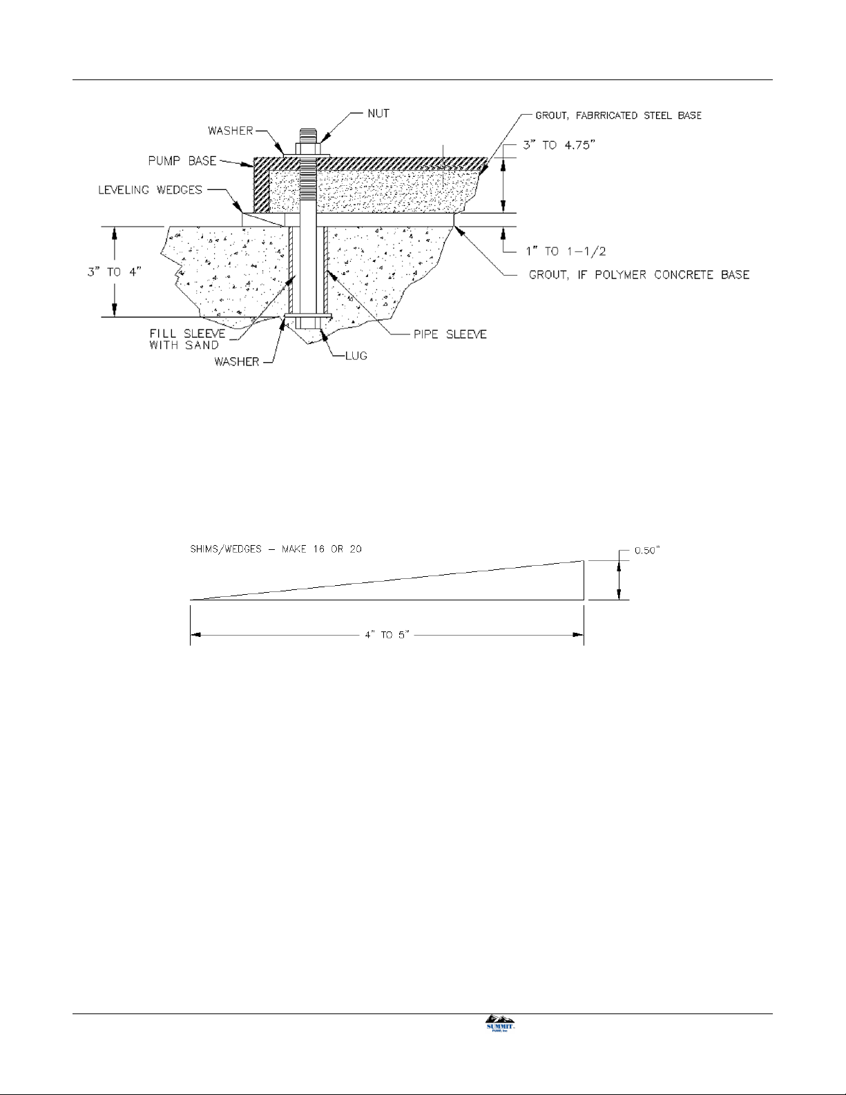
Figure 6-1: Anchor Bolt configuration
Figure 6-2: Wooden Wedges
6.5 BASE PLATE GROUTING
1. This grouting instruction assumes a concrete sub base has been put in place to accept the baseplate.
The subbase should be clean of dirt, oil and any other debris.
2. Shims/wedges should be wood.
3. Shims/wedges should be placed on the sub base, as shown in Figure 6-3. Use 2 to 3 per stack to
obtain desired gap between baseplate and sub-base. Normal gap is 1” to 1-1/2”.
4. Carefully lower baseplate with pump and motor onto sub base over anchor bolts.
5. Level baseplate to 0.125” over length and 0.088” in over width.
6. When leveling is complete, uniformly hand tighten the anchor bolts.
SUMMIT PUMP MODEL VV40 INTERNAL GEAR PUMP 9
Page 16

INSTALLATION, OPERATION, AND MAINTENANCE MANUAL
Figure 6-3: Wedge Locations
7. Build a plywood form around baseplate supported on the sub base. It should be 3” high and 1” to 1.5”
larger than the baseplate. Its size should be large enough to include the shims or wedges that are left
in place.
8. Use a high quality non-shrinking epoxy grout, following manufacturer’s mixing and installation
instructions.
9. When grout has cured, per grout manufacturer’s recommended cure time, tighten anchor bolts till
secure.
10. When grouting is complete, check coupling alignment and re-align as necessary.
10 SUMMIT PUMP MODEL VV40 INTERNAL GEAR PUMP
Page 17

INSTALLATION, OPERATION, AND MAINTENANCE MANUAL
Figure 6-4: Wet end configurations
6.6 ORIENTATION AND ROTATION
There are four main different wet end configurations for the VV40 pump. Refer to Figure 6-4 for the
different configurations. The configurations are dependent on two variables, casing orientation and shaft
rotation. The configurations are important to understand when installing the casing to the bracket and the
internal relief valve on the head. The internal relief valve must be positioned correctly or the valve will not
work correctly, potentially damaging equipment, severely injuring or causing death to personnel.
DANGER
Install pressure relief valve correctly to
avoid equipment failure, severe injury or
death.
SUMMIT PUMP MODEL VV40 INTERNAL GEAR PUMP 11
Page 18

INSTALLATION, OPERATION, AND MAINTENANCE MANUAL
6.6.1 Casing Orientation
To change the casing orientation, unbolt the casing from the bracket and rotate the casing and head 90degrees. Be careful as not to damage the idler, rotor or crescent shape inside the casing. The head plate
should rotate with the casing.
NOTICE
Rotate casing carefully as to not damage
internal parts.
6.7 PIPING CONNECTION – SUCTION / DISCHARGE
DANGER
Lock out driver power before beginning to
work on pump.
Connect piping in a manner that is as short and direct as possible. Independent pipe supports and anchors
must be used in all installations. Never support piping with pump flanges or threaded connections.
Ideally, you should place a short length of flexible or bellows type spool directly adjacent to the pump
flange.
CAUTION
Never use force to align piping to the pump
flanges or threaded connections.
6.7.1 Suction Piping
The piping used should be as short as possible from suction source. Piping line size should be the same
diameter as the suction nozzle. Although, this may not always be the case, as high viscosity, flow velocity or
system constraints may cause a change in size. All elbows 90° or 45° should be a long-sweep. Any piping
that causes air to become trapped should be avoided.
6.7.2 Discharge Piping
Generally, the diameter of the discharge piping should be the same diameter as the discharge nozzle. In
certain circumstances, this will not be the case, as the fluid being pumped will cause the use of a different
sized pipe. In these circumstances, the use of a threaded or flanged reducer/expansion fitting is needed.
It is recommended to install an isolation discharge valve to isolate the pump from the system when down for
maintenance.
12 SUMMIT PUMP MODEL VV40 INTERNAL GEAR PUMP
Page 19

INSTALLATION, OPERATION, AND MAINTENANCE MANUAL
6.8 ALIGNMENT
NOTICE
Careful alignment is extremely important to
ensure long pump life.
6.8.1 Coupling Connected Units
In-line configurations are shipped with the pump and motor leveled on the base plate with the coupling
disconnected. If the pump and driver were aligned at the factory, that alignment will be disturbed during
shipment. Alignment must be rechecked. If alignment is necessary, align the motor to the pump not the pump
to the motor. Check both parallel and angular alignments. Final alignment should be within 0.005" in all
planes at operating temperature.
6.8.2 Belt Driven Units
Check belt and sleeve alignment. Check belts for proper belt tension. Tension requirements will vary with
the type of belt, centerline distance and belt speeds. Consult belt manufacturer for specific recommendations.
6.8.3 Alignment Checks
Alignment checking needs to be done several times prior to pump start up. Alignment is accomplished by
adding or removing shims under the motor feet and moving the motor as required eliminating the
misalignment. Those alignment recommendations are as follows:
DANGER
Lock out driver power before beginning to
work on pump.
1. Prior to grouting, to remedy misalignment caused by transportation.
2. After grouting, to correct any changes that occurred during grouting.
3. After piping is connected, check alignments to ensure possible pipe strains have not changed
alignment.
4. Hot alignment, after the pump has reached operating temperature, if the pump is used in high
temperature service.
SUMMIT PUMP MODEL VV40 INTERNAL GEAR PUMP 13
Page 20

INSTALLATION, OPERATION, AND MAINTENANCE MANUAL
Figure 7-1: Lubrication locations
7 OPERATION
7.1 CHECKING ROTATION
The pump can operate equally well in a clockwise or counterclockwise rotation. The desired port to be
suction determines shaft rotation. Port closest to where pumping elements (gear teeth) come out of mesh is
suction port. If fitted with a pressure relief valve ensure the adjustment knob is near the suction port. See
Figure 6-4 for illustration.
DANGER
Lock out power to avoid personal injury or
death.
1. Lockout power to drive.
2. Remove coupling guard.
3. Remove coupling grid/sleeve element so that the motor half of coupling can spin free from the pump
half.
4. Unlock power to motor.
5. Clear personnel from immediate area, jog motor just enough to determine direction of rotation.
6. If the motor is rotating in the wrong direction the electrical wiring will need to be adjusted by
qualified personnel. Then repeat Step 4, 5 and 6.
7. Once rotation is in the desired direction, lockout motor and reassemble coupling grid/sleeve to
connect pump half.
8. Check alignment and install coupling guard.
9. Unlock motor, pump is ready to run.
7.2 LUBRICATION
7.2.1 Packing
The packing should be greased with 2 to 3
pumps of grease for grease lubricated
packing. Acceptable greases are shown in
Table 7-1. Lubrication intervals may vary
depending on application. In general, regrease the packing every 500 hours or every
six months using the stuffing box grease
zerk shown in Figure 7-1. See Section 7.3.2
for more details.
14 SUMMIT PUMP MODEL VV40 INTERNAL GEAR PUMP
Page 21

INSTALLATION, OPERATION, AND MAINTENANCE MANUAL
NOTICE
Packing is not greased at the factory.
Lubricate packing before operation.
7.2.2 Bearings
The bearing(s) on Summit’s VV40 pumps are grease lubricated at the factory. Depending on pump
application, speed and size of bearing(s), the amount the bearing(s) is lubricated changes. In general, regrease the bearing(s) every 500 hours or every six months using the bearing grease zerk shown in Figure 7-1.
Bearing housing “free” volume should approximately be 50% full of grease, higher percentage in lower
speed applications and lower percentage in higher speed applications.
NOTICE
Avoid over greasing bearings. This will
induce heat and damage bearing(s).
If pump is disassembled ensure bearing is cleaned and repacked with fresh grease. Ensure all dirt and foreign
matter is removed before reassembly. When pump is assembled use a hand grease gun to grease port shown
in Figure 7-1.
7.2.3 Grease
Recommended grease lubrication for bearings and packing is NLG1 No. 2 for pumping temperatures -60⁰F
to 350⁰F. Any type of Ep Lithium soap based grease is acceptable. Sodium or Calcium based grease is not
acceptable. A list of some acceptable bearing grease is shown in Table 7-1.
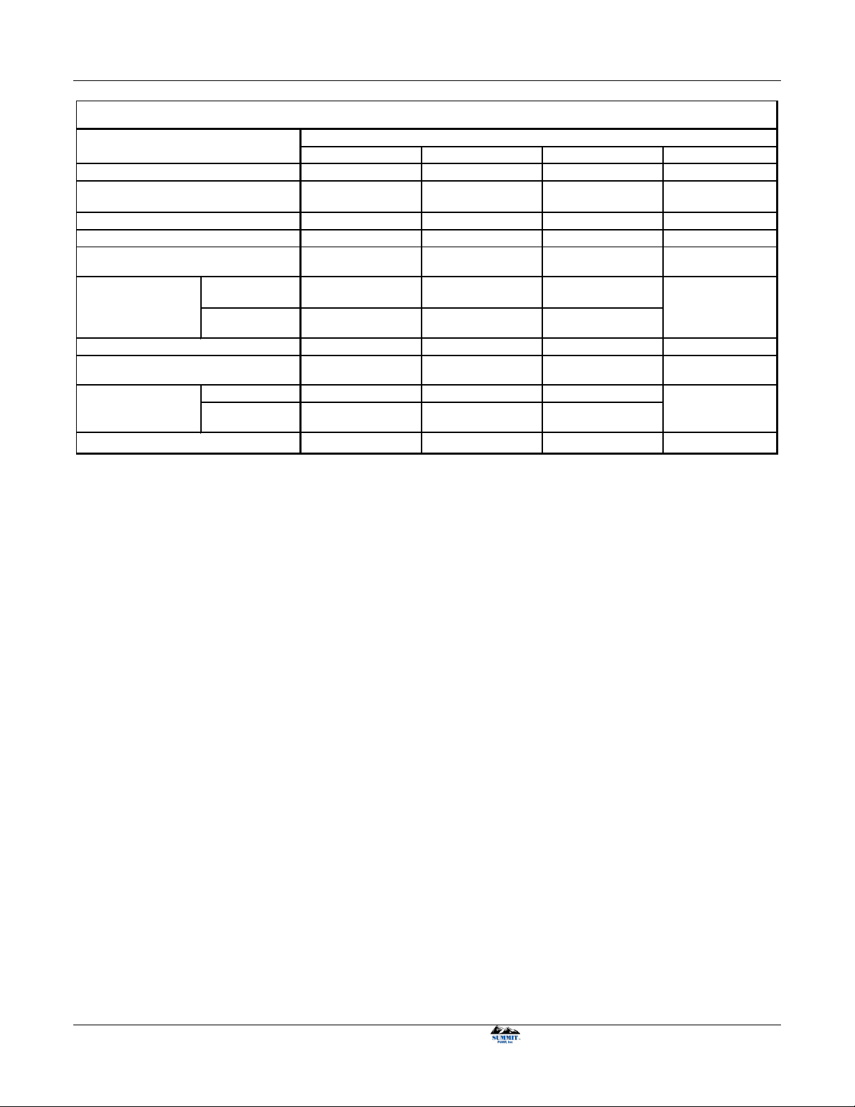
Table 7-1: Acceptable Bearing Greases NLG1 No. 2 Grade
Acceptable Greases
Citgo Mystic EP2
Keystone 81EP2
Mobil Mobilux EP2
Mobil Synthetic SCH 100
NOTICE
Grease lubricated pumps are intended to
use grease only. Do NOT add oil
7.3 PACKING
Packing must be lubricated and adjusted correctly to avoid seizing of packing and failure. Greased packing is
standard and is not lubricated at the factory. Packing lubrication must be done before operation.
SUMMIT PUMP MODEL VV40 INTERNAL GEAR PUMP 15
Page 22

INSTALLATION, OPERATION, AND MAINTENANCE MANUAL
IN
OUT
A B
C
D E F
DANGER
Lock out power to avoid personal injury or
death when working on pump.
7.3.1 Packing Adjustment
There are many variables that go into packing a pump correctly. Refer to the packing manufacture to
correctly set packing for specific application and material.
In general, before installing the packing, ensure all surfaces are clean of debris and packing size and material
are correct for specific application. Packing has a break-in period which is approximately two hours of
operation. During this time, allow liberal leakage which will set up a good sealing job.
After the break-in period, gradually tighten the packing gland using small incremented adjustments. Patience
is required between adjustments, having the gland too loose, rather than over tight, is ideal for reducing
shaft/packing wear resulting in sealing issues. A general drip rate guideline is 10 drops per minute per inch
of shaft diameter. (Example: 2.5 inch diameter shaft = 25 drops per minute)
7.3.2 Packing Lubrication
Packing can be grease lubricated or water lubricated. Water lubrication can be supplied from either an
external source or from the pumped product.
CAUTION
Packing must be lubricated to avoid seizing
of packing and sealing failure.
7.3.2.1 Greased Lubricated Packing (Standard)
A grease zerk is located in Figure 7-1. The packing should be greased after 500 hours of operation or sooner
when needed. More details can be found in Section 7.2.1
7.3.2.2 Water Lubricated Packing
A water flush is recommended when highly abrasive material is being pumped. The flush will prevent
packing leakage and excessive shaft wear. A clean water flush system is shown in Figure 7-2. Replace the
grease zerk with customer’s choice of fitting. The outlet can either be a tapped NPT hole in the stuffing box
opposite the inlet line or allow the water to leak out near the gland and into the casing. In either case, this
discharge of the flush water should be approximately 10-15 psi higher than the pressure in the casing.
16 SUMMIT PUMP MODEL VV40 INTERNAL GEAR PUMP
Page 23

INSTALLATION, OPERATION, AND MAINTENANCE MANUAL
Figure 7-2: Water Flush System
A) Y-strainer
B) Pressure regulating valve
C) Sight flow meter
D) Solenoid valve
E) Pressure gauge
F) Needle valve
7.4 MECHANICAL SEALS
For maximum seal life it is recommended to install a water flush line to keep seal faces free of debris. A
general example of a water flush system is shown in Figure 7-2 on page 17. Follow the steps necessary for
water flushed packing and apply to water flushed mechanical seals.
For component mechanical seal assembly refer to section 12.3.2 on page 32 and disassembly in section
11.3.2 on page 27.
7.5 FIRST RUN CHECK
Several items need to be checked before you put your pump into service. Each of the following items needs
to be addressed to make certain that your equipment is correctly installed.
1. Proper alignment of pump, coupling, driver and sheaves.
2. All electrical connections.
3. All instruments and gauges should be in working order.
4. Water flush connection to the stuffing box (if applicable).
5. Correct pump rotation as desired, see Figure 6-4 on page 17.
6. Open the valves on the suction and discharge.
DANGER
This is a positive displacement pump.
NEVER operate it against a closed valve or
clogged discharge.
NOTICE
Do not operate pump dry. Dry operation can
cause premature damage to pump
internals.
7.5.1 Start Up
1. Before operating the pump it must be filled with liquid. This can be done by removing the piping or pipe
plugs (item 30 in Figure 10-1 on page 24) and fill with pumping liquid or water. (Only use water if it will
not contaminate the pumping liquid.)
2. Ensure the motor rotation coincides with desired pump rotation. Refer to Section 6.6 on page 11 and 11
for specific shaft rotation direction.
SUMMIT PUMP MODEL VV40 INTERNAL GEAR PUMP 17
Page 24

INSTALLATION, OPERATION, AND MAINTENANCE MANUAL
3. If an internal relief valve is installed, make sure the threaded adjustment side is closest to the suction side
of the pump. See Figure 6-4 on page 11 for illustration.
4. If water flushed, turn on water to the stuffing box.
5. Start the pump.
DANGER
Do not operate the pump without the proper
coupling guard. See ANSI/ASME B15.1-
1996.
7.5.2
Shut Down
1. If possible, flush the pump with clean water. (Only use water if it will not contaminate the pumping
liquid.)
2. Shut down the pump.
3. If water flushed or water lubricated packing, turn off water to the stuffing box.
4. Close both the discharge and suction valves.
18 SUMMIT PUMP MODEL VV40 INTERNAL GEAR PUMP
Page 25

INSTALLATION, OPERATION, AND MAINTENANCE MANUAL
8 MAINTENANCE TIMETABLE
8.1 DAILY MAINTENANCE
1. Check the lip seals (05, Figure 10-1 on page 24) in the bearing housing for tears, worn areas and/or
leaks.
2. Inspect the packing or mechanical seal for correct flow, drip rate, noise and pressure.
8.2 THREE MONTH MAINTENANCE
1. Daily maintenance and the following:
2. Inspect and adjust packing so that drips are as stated in section 7.3.1 on page 16. If packing is grease
lubricated, lube the packing with 2 to 3 grease gun pumps, after 500 hours of operation or sooner
when needed.
8.3 SIX MONTH MAINTENANCE
1. Daily maintenance and the following:
2. The packing should be replaced.
3. Check lip seal (05, Figure 10-1 on page 24) and drive shaft for wear. The suction and discharge piping
spool pieces should be inspected internally for their condition.
4. Lubricate all grease fittings using a hand grease gun.
8.4 YEARLY MAINTENANCE
1. All of the above and the following:
2. Depending on the fluid pumped and pump operating hours, check pump performance with published
performance curve. These inspections can range from once a year, to once every three to five years.
SUMMIT PUMP MODEL VV40 INTERNAL GEAR PUMP 19
Page 26

INSTALLATION, OPERATION, AND MAINTENANCE MANUAL
Pump has run dry.
2
Liquid temperature higher than stated.
4
Viscosity higher than stated.
5
Parts not hardened.
8
Suction or differe ntial pressure too high.
9
Discharge valve not open or partially open.
12
Clogged strainer.
13
Wrong clearance setting for application.
17
Packing gland too tight or skewed.
19
Improper seal installed.
20
Relief valve improper pressure setting.
22
Relief valve reversed.
23
Mater ial compatibility.
24
Drive misalignment
27
Base plate loose
28
Drive not sized for horsepower required.
29
9 TROUBLESHOOTING
9.1 PUMP PROBLEMS
Pump turns, no flow. 1,2,3,10,12,13,14,15,16,17,18
Pump flow rate below expected capacity. 1,2,3,4,5,6,7,10,11,12,13,16,17,18,22,25
Pump will not produce rated pressure. 1,2,3,4,11,13,16,17,18,22,29
Pump develops too much pressure. 6,7,9,12,17,21,23
Pump no longer self-primes. 2,3,4,5,7,10,11,13,14,15,16,17,18,20,24,26
Pump won't turn/motor overloads. 5,6,7,12,15,17,19,21,24,26,27,29
Pump is very noisy/excessive vibrat ion. 1,2,3,5,6,7,10,11,13,14,18,20,21,26,27,28
Pump runs hot. 4,5,6,7,12,17,18,19,21,22,24,26,27,29
Pump seals short life. 1,2,3,4,5,6,7,9,10,11,12,13,17,18,19,20,21,22,23,24,26,27,28
Packing short life. 2,3,4,6,7,9,10,11,12,13,14,17,18,19,20,21,24,27,28
Excessive internal wear. 1,2,3,6,7,8,9,12,13,14,16,17,18,19,21,23,24,26,27,28
9.2 PROBABLE CAUSE AND REMEDY.
NPSHA not sufficient. 1
Air leaking into the pump. 3
Pump running too fast for application. 6
Abrasives in liquid. 7
Suctio n valve not open. 10
Suctio n valve partia lly open. 11
Supply vessel e mpty. 14
Pump rotation wrong. 15
Incorrect head placement. 16
Worn pump internals. 18
Inadequate lubrication. 21
Bad bearing (thrust). 26
20 SUMMIT PUMP MODEL VV40 INTERNAL GEAR PUMP
Page 27

INSTALLATION, OPERATION, AND MAINTENANCE MANUAL
Figure 10-1: VV40H & VV40HL Exploded View – Cast Iron
Table 10-1: Itemized Parts
01
LOCK NUT 17 PAC KING GL AND CAP SCREW 35 HEAD GASKET
02 LOC K WASHER 19
PAC KING RING/MEC HANICAL S EAL
36
ROTOR AND SHAFT
03 END CAP FOR BEARING HOUSING 20 RETAINING RING 37 IDLER AND BUSHING ASSEMBLY
04 BEARI NG SPACER C OLLAR 21 MECHANIC AL SEAL COLL AR 38 IDLER BUSHING
05 LIP SEAL 25 BRAC KET BUSHING 39 IDLER PIN
06 BAL L BEARI NG 27 BRAC KET AND B USHIN G 40 HEAD AND IDLER PIN ASSEMBLY
07 BEARING HOUSING 28 CAP SCREW FOR BRACKET 43 CAP SCREW FOR H EAD
12 GREAS E FITTING 29 BRAC KET GASK ET 45 REL IEF VALVE GASK ET
15 PAC KING GL AND 30 PIPE PLUG 46 CAP SCREW FOR VAL VE
16 NUT, SELF LOCKING 31 CASI NG 47 REL IEF VALVE
MODEL VV4 0H & HL INTERNAL GEAR PUMP
1
THROUGH
7
BEARI NG HOUSING ASSEMBL Y (COMPL ETE)
INCLUD ES BEARING HOUSING SET SCREW, INSERTS, END CAP SET SCREW
10 EXPLODED VIEWS
Use below figures and tables with respect to Section 11 DISASSEMBLY MODEL VV40 and Section 12
ASSEMBLY MODEL VV40
10.1 VV40H & VV40HL Cast Iron
SUMMIT PUMP MODEL VV40 INTERNAL GEAR PUMP 21
Page 28

INSTALLATION, OPERATION, AND MAINTENANCE MANUAL
01 LOCK NUT 17 PAC KING GL AND CAP SCREW 36 ROTOR AND SHAFT
02 LOC K WASHER 19
PAC KING RING/MEC HANICAL S EAL
37 IDLER AND BUSHING ASSEMBLY
03 END CAP FOR BEARING HOUSING 20 RETAINING RING 38 IDLER BUSHING
04 BEARI NG SPACER C OLLAR 25 BRAC KET BUSHING 39 IDLER PIN
05 LIP SEAL 27 BRAC KET AND B USHING 40 HEAD AND IDLER PIN ASSEMBLY
06 BAL L BEARI NG 28 CAP SCREW FOR BRACKET 43 CAP SCREW FOR HEAD
07 BEARING HOUSING 29 BRACK ET GASKET 45 REL IEF VALVE GASK ET
12 GREAS E FITTING 30 PIPE PLUG 46 CAP SCREW FOR VALVE
15 PAC KING GL AND 31 CASING 47 RELIEF VAL VE
16 NUT, SELF LOCKING 35 HEAD GASKET
MODEL VV40H VV40HL INTERNAL GEAR PUMP
1
THROUGH
7
BEARI NG HOUSING ASSEMBL Y (COMPL ETE)
INCLUD ES BEARING HOUSING SET SCREW, INSERTS, END CAP SET SCREW
Figure 10-2: VV40H & VV40HL Exploded View - Stainless Steel
Table 10-2: Itemized Parts
10.2 VV40H & VV40HL Stainless Steel
22 SUMMIT PUMP MODEL VV40 INTERNAL GEAR PUMP
Page 29

INSTALLATION, OPERATION, AND MAINTENANCE MANUAL
01 LOCK NUT 19 COMP ONENT MECHANIC AL SEAL 36 ROTOR AND S HAFT
02 LOC K WASHER 25 BRACKET BUSHING 37 IDLER AND BUSHING ASSEMBLY
03 END CAP FOR BEARING HOUSING 26 PRESSURE RELIEF PLUG 38 IDLER BUSHING
04 BEARI NG SPACER C OLLAR 27 BRACKET AND B USHING 39 IDLER PIN
05 LIP SEAL 28 CAP SCREW 40 HEAD AND IDLER PIN ASSEMBLY
06 BAL L BEARI NG 29 BRACKET GASK ET 43 CAP SCREW FOR HEAD
07 BEARING HOUSING 30 PIPE PLUG 45 RELI EF VALVE G ASKET
12 GREAS E FITTING 31 CASING 46 CAP SCREW FOR VALVE
18 LI P SEAL (FOR CHAMBER) 35 H EAD GASK ET 47 RELI EF VALVE
BEHIND ROTOR SEAL : VV40H & VV40HL INTERNAL GEAR PUMP
1
THROUGH
7
BEARI NG HOUSING ASSEMBL Y (COMPL ETE)
INCLUD ES: BEARING HOUSING SET SCREW, INSERTS & END CAP SET SCREW
10.3 VV40H & VV40HL Cast Iron & Stainless Steel – Behind Rotor Mechanical Seal
Figure 10-3: VV40H & VV40HL Behind Rotor Seal
Table 10-3: Itemized Parts
SUMMIT PUMP MODEL VV40 INTERNAL GEAR PUMP 23
Page 30

INSTALLATION, OPERATION, AND MAINTENANCE MANUAL
Figure 10-4: VV40L, LL, LQ, LS Exploded view Cast Iron and Stainless Steel. Note: VV40L in not
available in Stainless
Table 10-4: Itemized Parts
ITEM D ESCRIPTION ITEM D ES CRIPTION ITEM DESCRIPTION
01 LOC K NUT PACKI NG 36 ROTOR AND SHAFT
02 LOCK WASHER COMP ONENT MECHANICAL SEAL 37 IDLER AND BUSHING ASSEMBLY
03 END CAP FOR BEARING HOUSING 20 PAC KING RETAINING W ASHER 38 IDLER BUSHING
04 BEARI NG SPACER COL LAR (OUTER ) 21 MECHANIC AL SEAL COLL AR 39 IDLER PIN
05 LI P SEAL 22** SEAL HOLD ER 40 HEAD AND IDLER PIN ASSEMBLY
06 BEARI NG(S) 23** S EAL HOL DER PLATE 41* O-RING FOR J ACKET HEAD P LATE
07 BEARING HOUSING 25 BRAC KET BUSHING 42* J ACKET H EAD PL ATE
08 BEARING SPACER COLLAR (INNER) 27 BRAC KET AND B USHING 43 CAP SCREW FOR PL AIN OR VALVE TYP E HEAD
11 RING, HALF ROUND 28 CAP SCREW FOR BRACKET 45 REL IEF VALVE GASK ET
12 GREAS E FITTING 29 BRACKET GASKET 46 CAP SCREW FOR VALVE
15 PAC KING /MECHANICAL SEAL GL AND 30 PIPE PLUG 47 I NTERNAL RELIEF VAL VE
16 PAC KING /SEAL GL AND NUT SELF LOCK ING 31 CASING BEARING HOUSING ASSEMBLY
17 PAC KING /SEAL GL AND CAP SCREW 35 HEAD GASKET BEARING HOUSING SET SCREW
* NOT SHOWN INS ERTS
** NOT SHOWN; LS, Q AND QS SIZES ONLY END C AP SET SC REW
19
1
THROUGH
11
MODEL VV4 0 INTERN AL GEAR PUMP
10.4 VV40L, LL, LQ & LS Cast Iron & Stainless Steel
Note: Item 21 is not present with Stainless Steel externals
24 SUMMIT PUMP MODEL VV40 INTERNAL GEAR PUMP
Page 31

INSTALLATION, OPERATION, AND MAINTENANCE MANUAL
11 DISASSEMBLY MODEL VV40
This section will cover sizes: H, HL, AK, AL, K, KK, L, LQ, LL, LS, Q, and QS. It must be noted that
although there are slight differences within these sizes, the disassembly and assembly procedures follow the
same progression. Use the following steps as a general guideline, as it is impractical to cover every situation.
Refer to Figure 10-1 and Table 10-1 on page 24 for part’s item number reference.
Notes:
• Sizes H though L, for cast iron externals, have a NPT suction and discharge port. Ductile iron, steel
and stainless steel externals may or may not have a NPT pipe connections. Although, this will not
affect disassembly or assembly of the pump, it will alter how piping will be connected and
disconnected.
• Sizes Q and QS have two tapered roller bearings (06). These sizes also utilize threaded studs and nuts
for piping connections, as well as head (40) to casing (31) connections. For Q and QS component
seals, item number (15) becomes items: seal holder (22) and seal holder plate (23). During assembly
or disassembly refer to item (15) as items (22) and (23).
• The casing on size QS will have suction and discharge ports 180 degrees apart from each other
versus 90 degrees on other sizes.
• Item 36, rotor and shaft (36) is one piece. This may be referenced as “shaft (36)”, “rotor (36)” or
“rotor and shaft (36)”.
DANGER
Lock out power to avoid personal injury or
death when working on packing.
DANGER
Properly vent any pressure in pump, fittings
and connecting lines.
WARNING
Understand material being pumped. Obtain
MSDS information for product. Take all
necessary precautions.
WARNING
Wear eye protection and proper personal
protective equipment.
SUMMIT PUMP MODEL VV40 INTERNAL GEAR PUMP 25
Page 32

INSTALLATION, OPERATION, AND MAINTENANCE MANUAL
NOTICE
Secure pump before disassembly to avoid
damage. Pump’s center of gravity changes
when removing parts.
11.1 HEAD AND CASING
1. Remove pipe plug (30) in lower section of bracket (27) to drain fluid from casing and piping.
2. Mark head (40) and casing (31) alignment using a permanent marker before disassembly. It is critical
to keep head (40) and casing (31) orientation the same for proper performance.
3. Remove cap screws (43), head (40) and, if equipped, internal relief valve (47) (Instructions for
internal relief valve disassembly refer to Section 11.5).Take care not to damage the head gasket (35)
and idler (37). When removing, tilt the head (40) away from the casing to avoid the idler (37) falling
off the idler pin (39), to avoid damaged.
If pump is jacketed, remove jacket head plate (42) and O-ring (41) at this point. Note: Items (42) and
(41) are not shown in Figure 10-1.
4. Remove idler and bushing assembly (37). Visually check for wear and damage, replace if needed. If
necessary, remove idler bushing (38) using a press. Refer to Section 12.1 on page 29 for more
bushing details.
5. Separate head gasket (35) from head (40) and set aside, replace if damaged or needed. Press out idler
pin (39) if needed.
11.2 BEARING HOUSING
1. Bend up the locking tang on the lock washer (02). To remove locknut (01) place a hard wood board
or a soft brass bar through the suction or discharge ports and into the teeth of the rotor (36). This will
keep the rotating components from moving. Using a spanner wrench turn the locknut (01) counterclockwise to remove and discard. Upon reassembly replace with new locknut (01)
2. Slide off lock washer (02) and discard. Upon reassembly replace with a new lock washer (02).
3. Remove set screws (Bearing Housing Set Screw) on bearing housing (07) flange and set aside.
Remove the bearing housing (07) assembly by rotating counter-clockwise (as viewed from the drive
end).
4. Remove set screws (End Cap Set Screws) and white inserts (Inserts) in the bearing housing (07)
flange. This will allow the end cap (03) to be removed. Rotate the end cap (03) counter-clockwise to
remove from the bearing housing (07).
26 SUMMIT PUMP MODEL VV40 INTERNAL GEAR PUMP
Page 33

INSTALLATION, OPERATION, AND MAINTENANCE MANUAL
NOTICE
Do not change positions of inner and outer
tapered roller bearing – for Q and QS sizes.
5. Remove outboard lip seal (05), outer bearing spacer collar (04), bearing (06), inboard lip seal (05),
inner bearing spacer collar (08) and half round ring (11). Check all components for wear or damage,
it is recommended to replace lip seals (05). Note: half round ring (11) is not present for H, HL, Q
and QS sizes.
11.3 REMOVING SEALS
1. Remove the packing/seal gland nuts (16) and packing/seal gland cap screw (17).
2. Slide the packing/mechanical seal gland (15) off the rotor and shaft (36) and place next to gland nuts
(16) and gland cap screw (17).
Continue to step three in sections 11.3.1 and 11.3.2 for packing or component mechanical seal
respectively.
11.3.1 Packing
3. Using a packing hook, remove the packing (19) from the stuffing box. Be careful not to damage
stuffing box bore. Refer to packing manufacturer for recommended hours of use before needing
replacement.
4. Remove packing retaining washer (20).
5. With a mirror, inspect the shaft (36) for wear. If worn, the shaft (36) will need to be replaced; see
Section 11.4 for rotor and shaft (36) removal. Note: Rotor and shaft (36) is one piece.
11.3.2 Component Mechanical Seal
3. Remove the mechanical seal (19) from the bracket (27) being careful not to damage the elastomers or
sealing faces.
4. To remove the mechanical seal collar (21), remove pipe plugs (30) from the bracket (27) located on
the stuffing box to access the set screws on the mechanical seal collar (21). Rotate the rotor and shaft
(36) to line up set screws with the pipe plug (30) hole opening. Use a hex-head wrench on the
mechanical seal collar’s (21) set screws and loosen all set screws.
5. It is a good idea to mark the shaft (36) where the mechanical seal collar (21) was originally set to
assist with reassembly. Slide the mechanical seal collar (21) off the rotor and shaft (36).
6. Inspect bracket (27), rotor and shaft (36) and mechanical seal (19) for damage or wear. If needed
replace parts.
SUMMIT PUMP MODEL VV40 INTERNAL GEAR PUMP 27
Page 34

INSTALLATION, OPERATION, AND MAINTENANCE MANUAL
11.4 BRACKET AND CASING
1. Carefully slide out rotor and shaft (36) as not to damage the bracket bushing (25). Do not separate
rotor and shaft (36).
2. Remove cap screws (28) from the bracket (27). Support the weight of the casing (31) as not to
damage threads on cap screws (28) or the casing (31) when removing.
3. Remove bracket gasket (29), replace if damaged.
4. Remove bracket bushing (25), if needed, utilizing a press.
11.5 INTERNAL RELIEF VALVE
1. Mark the orientation of the internal relieve valve (47) with the head (40). Note the side with the
adjustment screw is always nearest the suction port. If installed improperly the valve will act as a
plug and will not bypass fluid when pressure limit is reached.
DANGER
Mark valve orientation. Improper installment
may result in equipment loss, serious injury
or death.
2. Remove cap screws (46) and pull off internal relief valve (47). Be careful as not to damage relief
valve gaskets (45).
28 SUMMIT PUMP MODEL VV40 INTERNAL GEAR PUMP
Page 35

INSTALLATION, OPERATION, AND MAINTENANCE MANUAL
12 ASSEMBLY MODEL VV40
This section will cover sizes: H, HL, AK, AL, K, KK, L, LQ, LL, LS, Q, and QS. It must be noted that
although there are slight difference within these sizes the disassembly and assembly procedures follow the
same progression. Use the following steps as a general guideline as it is impractical to cover every situation.
It is vital during assembly to ensure cleanliness. Especially for bearings, mechanical seal, packing and lip
seals. Check all parts for damage, nicks and wear. Inspect all tapped holes; chase threads as needed. If
damage or wear is found, replace parts to avoid premature failure.
Notes:
• Sizes H though L, for cast iron externals, have a NPT suction and discharge port. Ductile iron, steel
and stainless steel externals may or may not have a NPT pipe connections. Although, this will not
affect disassembly or assembly of the pump, it will alter how piping will be connected and
disconnected.
• Sizes Q and QS have two roller bearings (06). These sizes also utilize threaded studs and nuts for
piping connections and head (40) to casing (31) connections. For Q and QS component seals, item
number (15) becomes items, seal holder (22) and seal holder plate (23). During assembly or
disassembly refer to item (15) as items (22) and (23).
• The casing on size QS will have suction and discharge ports 180 degrees apart from each other
versus 90 degrees on other sizes.
DANGER
Lock out power to avoid personal injury or
death.
NOTICE
Secure pump before assembly to avoid
damage. Pump’s center of gravity changes
when adding parts.
DANGER
Operation of any positive displacement
pump with a clogged discharge or closed
discharge valve generates a pressure
vessel. Ensure a safety valve is fitted
correctly in system.
12.1 BRACKET & IDLER BUSHINGS
The following steps are written in terms of the bracket bushing (25) and bracket (27). When installing the
idler bushing (38) with the idler (37), replace the verbiage: “bracket bushing (25)” with “idler bushing (38)”
and “bracket (27)” with “idler (38)”.
SUMMIT PUMP MODEL VV40 INTERNAL GEAR PUMP 29
Page 36

INSTALLATION, OPERATION, AND MAINTENANCE MANUAL
These steps are both written for bronze and carbon graphite bushings. Take extreme care with the carbon
graphite bushing, as they are very brittle and easily cracked.
12.1.1 Normal installation
1. Inspect bracket (27) for wear or damage and clean to avoid contamination of bearings and bracket
bushing (25).
2. Chamfer the leading edge of bracket bushing (25) and the bore entry on bracket (27), if not already.
This will assist with lining up both parts. Lubricate bracket bushing’s (25) outer diameter and
bracket’s (27) inner diameter.
3. Use a press to install bracket bushing (25). Ensure both parts are square to each other and if bracket
bushing (25) has a groove install bushing so that groove is in the 6-oclock position.
Once pressing, do not stop until bracket bushing (25) is located in the proper position; which is even
with the bracket’s (27) machined surface. Starting and stopping will crack the bracket bushing (25)
and cause premature failure.
4. Check for cracks in the bracket bushing (25). Any cracks will reduce bushing life and increase shaft
ware. It is recommended to remove and replace bushing if any cracks are detected.
12.1.2 Heated installation
CAUTION
Wear proper personal protective equipment
to avoid burns from hot parts.
This is the recommended installation process for the carbon graphite bushing. Since the carbon graphite
bushing is very brittle, there is less risk of cracking in this process.
1. Inspect bracket (27) for wear or damage and clean to avoid contamination of bearing and bracket
bushing (25).
2. Slowly and thoroughly heat bracket (27) in the bracket bushing (25) installation location. The lower
the bracket (27) temperature the higher the risk of cracking the bushing.
3. Use a press to install a cool bracket bushing (25). Ensure both parts are square to each other and if
bracket bushing (25) has a groove install bushing so that groove is in the 6-oclock position.
Once pressing, do not stop until bracket bushing (25) is located in the proper position; which is even
with the bracket’s (27) machined surface. Starting and stopping will crack the bracket bushing (25)
and cause premature failure.
4. Check for cracks in the bracket bushing (25). Any cracks will reduce bushing life and increase shaft
ware. It is recommended to remove and replace bushing if any cracks are detected.
30 SUMMIT PUMP MODEL VV40 INTERNAL GEAR PUMP
Page 37

INSTALLATION, OPERATION, AND MAINTENANCE MANUAL
Bronze
Iron
Stainless
Steel
All
VV40H
VV40HL
600 375 450
VV40K
VV40KK
575 350 450
VV40L
VV40LQ
VV40LL
525 350 450
VV40LS
540 345 450
VV40Q
VV40QS
400 270 450
Bushing Material
Carbon Graphite
Pump Material
Temperature (°F)
Pump
Size
Table 12-1: Fluid temperature limits for bushings.
12.1.3 Bushing Temperature Limits
Table 12-1 shows fluid temperature limits for Bronze and Carbon Graphite bushings when installed in
corresponding idler materials for different pump sizes.
The carbon graphic temperature limits are based on thermal expansion rates and the requirement of an
interference fit. The temperature limit with the bronze bushing is a limit of the bronze material and not an
interference fit issue.
12.2 BRACKET AND CASING
1. Install new bracket gasket (29), hold in place by conservatively applying compatible light grease or
oil.
2. Attach casing (31) and orientate casing in desired configuration as shown in Figure 6-4 on page 11.
3. Support casing (31) while attaching cap screws (28) and hand tighten. Sequence tighten cap screws
(28) and tighten per bolt torque in Table 13-1 in Section 13.1.
4. Clean shaft and rotor (36). Closely inspect for wear or damage paying particular attention to the
bearing journal.
5. Carefully slide shaft and rotor (36) though bracket bushing (25) as not to damage the bracket bushing
(25). Slide shaft and rotor (36) until rotor mates with the bracket (27).
12.3 INSTALLING SEALS
There are three primary ways to seal the VV40 pumps; packing (standard), component mechanical seal or
cartridge mechanical seal. For third party mechanical seal assembly and disassembly, refer to seal
manufacturer’s installation and operation manual.
SUMMIT PUMP MODEL VV40 INTERNAL GEAR PUMP 31
Page 38

INSTALLATION, OPERATION, AND MAINTENANCE MANUAL
Model
and Size
VV40H
VV40HL
VV40AK
VV40AL
VV40K
VV40KK
VV40L
VV40LQ
VV40LL
VV40L
VV40LQ
VV40LL
"E"
si z e d
shaft
(1 5/8")
VV40LS
VV40Q
VV40QS
Number of
Rings
5 6 6
7 7
Pa cking
Size
7/16" 7/16" 3/8"
3/8" 1/2"
Table 12-2: Packing sizes and number of rings
12.3.1 Packing
1. Inspect the stuffing box for debris or damage. If needed, replace the bracket (27). Clean bracket (27)
and shaft (36) thoroughly to avoid any sealing issues.
2. Choose packing carefully, depending on pumped fluid. Follow all packing manufacturer’s
instructions.
3. Prepare packing rings by wrapping the packing around a mandrel which has the same diameter as the
shaft (36). The number of wraps should equal the number of rings needed for the particular pump as
shown in Table 12-1. Cut packing at a 45 degree or 90 degree angle.
4. Install packing retaining washer (20) into the stuffing box, followed by packing (19) rings. Install one
ring at a time ensuring a square fit. If desired, lubricate packing (19) and shaft (36) conservatively
with compatible grease. When adding packing (19) rings, allow ring joints to be kept at least 90
degrees apart from adjacent ring joints.
5. When final packing (19) ring is installed, slide packing/seal gland cap screw (17) into bracket (27).
6. Install the packing/mechanical seal gland (15) and secure using the packing/seal gland nut (16) finger
tight. More adjustments will be needed during operation to achieve desired drip rate.
For Q and QS sizes, do not tighten packing/mechanical seal gland nuts (16) until after the cap screw
(03) has been installed and properly tightened per instructions in Section 12.4 step 8. If gland nuts
(16) are tight it will make it difficult to rotate shaft by hand.
12.3.2 Component Mechanical Seal
The component mechanical seal is a type 1 or type 9 mechanical seal. It is an alternative to packing or a
cartridge seal.
1. Inspect the stuffing box for debris or damage. Clean bracket (27) and shaft (36) thoroughly to avoid
any sealing issues, if needed, replace parts. It is recommended that component seals be replaced each
time pump is rebuilt.
2. Remove pipe plugs (30) from the bracket (27) located on the stuffing box. These are the access ports
32 SUMMIT PUMP MODEL VV40 INTERNAL GEAR PUMP
to lock down the mechanical seal collar (21) to the shaft (36).
Page 39

INSTALLATION, OPERATION, AND MAINTENANCE MANUAL
3. Install the mechanical seal collar (21) over the shaft (31) and into the stuffing box. Line up the
locking set screws in the mechanical seal collar (21) with the previous marks on the shaft (36) or
marked location created during disassembly. If no marks are visible, approximate the mechanical seal
collar (21) set distance.
4. Tighten the set screw in the mechanical seal collar (21) with a hex wrench via pipe plug ports located
on the stuffing box. Rotate the shaft to access the set screws in the mechanical seal collar (21).
5. Coat the shaft (36), tapered installation sleeve, and mating parts of the component mechanical seal
(19) with a generous amount of compatible lubricant; grease is not recommended.
6. Slide the component mechanical seal (19) over the shaft and tapered installation sleeve into the
stuffing box until set against the mechanical seal collar (21). Be careful not to bump the threads on
the shaft (36) potentially damaging the elastomers on the component mechanical seal (19). If holding
clips are present to hold spring in place, remove clips to free spring after seal is installed.
7. Remove the tapered installation sleeve and replace pipe plugs (30) from bracket (27) located on the
stuffing box.
8. Install the packing/mechanical seal gland (15) and secure using packing/seal gland nut (16) finger
tight.
For Q and QS sizes, do not tighten packing/mechanical seal gland nuts (16) until after the cap screw
(03) has been installed and properly tightened per instructions in Section 1 step 8. If gland nuts (16)
are tight it will make it difficult to rotate shaft by hand.
12.4 BEARING HOUSING
This section will cover the assembly of parts with item numbers 01 to 11. Carefully examine all parts for
wear or damage and replace when needed. Replace locknut (01), lock washer (02) and lip seals (05) with
new parts.
1. Slide on half round rings (11) on to shaft (36) to shoulder with radial groove. Hold half round rings
(11) in place with one hand. Note: sizes H, HL, Q and QS do not have half round rings (11).
2. Orientate inner bearing spacer collar (08) with the other hand so that the recessed end is facing the
casing (31). Slide inner bearing spacer collar (08) over the shaft and mate with half round rings (11).
Note: sizes H, HL, Q and QS inner bearing spacer collar (08) will not have recessed end.
3. Install lip seal (05) into the bearing housing (07). Position lip seal (05) with sealing lip facing the
drive end (spring side open to the drive end). Slide lip seal (05) into the bearing housing (07) until
the lip seal (05) rests against the deepest shoulder.
4. Position the bearing housing (07) over the shaft and thread in the bearing housing (07) to the bracket
(27). Be careful as not to damage the lip seal (05) on the threads for the locknut (01).
5. Pack the ball bearing (06) with acceptable grease. Acceptable grease is stated in Section 7.2.3 on
page 15. Position the bearing (06) over the shaft and push or press into the bearing housing (07).
Q and QS have two bearings and they are tapered roller bearings (06), orientation does matter for
SUMMIT PUMP MODEL VV40 INTERNAL GEAR PUMP 33
Page 40

INSTALLATION, OPERATION, AND MAINTENANCE MANUAL
installation. Large end of inner raceways must mate together letting the rollers angle away from each
other.
6. Slide the outer bearing spacer collar (04) over the drive end side of the shaft (36) and mate it with the
bearing (06).
7. Install lip seal (05) in the end cap (03) with sealing lip facing the drive end when end cap (03) is
installed (spring should be open to the drive end side after installation of end cap (03)).
8. Thread the end cap (03) into the bearing housing (07) and tighten with a spanner wrench against the
bearing (06). Insert inserts and end cap set screws to lock the end cap (03) in place.
Q and QS sizes have tapered roller bearings and preload must be set for proper operation. Preload is
set by turning the end cap (03) in or out of the bearing housing (07).
a. Thread in end cap (03) until it lightly touches the bearing (06).
b. Turn the shaft (36) by hand to reference the amount of resistance while rotating.
c. Thread in the end cap (03) with a spanner wrench until the shaft (36) is no longer able to turn
by hand.
d. Back out the end cap (03) until the shaft (36) is able to turn again with slight but noticeable
resistance.
9. Place lock washer (02) and locknut (01) over the shaft. Tighten locknut to corresponding values in
Table 13-2 on page 40. Once locknut (01) is properly torqued, bend down tang on lock washer (02)
to prevent locknut (01) from rotating.
Install bearing housing set screws after adjusting the end clearance.
12.5 HEAD AND CASING
1. Press idler pin (39) into the head (40). If idler pin (39) is lube type, ensure the end with the threaded
hole is facing outward away from the casing (31).
2. Fit a new head gasket (35) onto the head (40). Add a small amount of grease or oil to keep head
gasket (35) in place.
3. Slide idler and bushing assembly (37) over idler pin (39). If idler bushing (38) is not installed in idler
(37) refer to Section 12.1 BRACKET & IDLER BUSHINGS on page 29 for installation of idler
bushing (38).
4. Identify orientation marks that were made during disassembly in Section 11.1 on page 26. It is
critical to get head (40) orientation correct for proper pump performance. As rule-of-thumb, the
crescent shape on the head (40) should be about 135 degrees away from discharge and suction ports.
5. Once head (40) is in the correct orientation, mate head (40) with the casing (31) lining up the cap
screw (43) holes. Hold head (40) in place and hand tighten cap screws (43). Torque the cap screws
(43) in proper sequence to torque values shown in Table 13-1 on page 40.
34 SUMMIT PUMP MODEL VV40 INTERNAL GEAR PUMP
Page 41

INSTALLATION, OPERATION, AND MAINTENANCE MANUAL
Figure 12-1: Dimension CL defined
Figure 12-2: Dimension AC defined
If pump is jacketed, install jacket head plate (42) and O-ring (41) at this point using cap screws (43).
Note: Items (42) and (41) are not shown in Figure 10-1.
12.6 ADJUSTING END CLEARANCE
12.6.1 Measured Rotation Method
Standard end clearance is set at the factory. End clearance
adjustment is needed to provide proper pump performance
and spacing between the rotor (36), idler (37) and head (40).
End clearance is adjusted by rotating the bearing housing
(07) clockwise or counter clockwise. Clockwise to make
tighter clearances and counter clockwise to open clearances.
The following steps explain the process of setting the correct
end clearance.
1. Loosen bearing housing set
screws, if installed, on the
flange of the bearing housing
(07).
2. Rotate bearing housing (07)
clockwise by hand until it
can no longer be turned.
Ensure rotor and shaft (36)
cannot be rotated by hand.
3. Rotate bearing housing (07)
counter clockwise until shaft
(36) can be turned with only
a slight noticeable drag. This will be the “zero” setting.
4. Table 12-3 shows the standard end clearances for available VV40 models. To set end clearance,
rotate bearing housing (07) counter-clockwise as indicated by arc length “AC” in Table 12-2.
5. After setting end clearance, replace bearing housing set screws to lock bearing housing (07) in place
during operation.
6. It may be necessary to add extra end clearance for higher viscosity fluids. Contact your local Summit
Pump, Inc. Distributor for specifications.
SUMMIT PUMP MODEL VV40 INTERNAL GEAR PUMP 35
Page 42

INSTALLATION, OPERATION, AND MAINTENANCE MANUAL
Table 12-3: End clearances, arc lengths and arc lengths per 0.001” of
end clearance.
Standard End
Clearance
(in)
Distance on OD of
Bracket for
Standard End
Clearance
(in)
Distance on Bracket OD
for 0.001" End
Clearance
(in)
CL
AC AC for CL=0.001"
(C) Cast Iron,
(D) Ductile Iron,
(W) Steel
0.003 0.750 0.25
(S) Stainless
Steel
0.005 1.125 0.23
(C) Cast Iron,
(D) Ductile Iron,
(W) Steel
0.005 1.250 0.25
(S) Stainless
Steel
0.008
2.000 0.25
(C) Cast Iron,
(D) Ductile Iron,
(W) Steel
0.005
1.250 0.25
(S) Stainless
Steel
(C) Cast Iron w/
"E" sized shaft
(1 5/8")
0.010 2.500 0.25
(C) Cast Iron,
(D) Ductile Iron,
(W) Steel,
(S) Stainless Steel
0.010 3.100 0.31
(C) Cast Iron w/
"E" sized shaft
(1 5/8")
0.015 4.650 0.31
VV40H
VV40HL
VV40AK
VV40AL
VV40K
VV40KK
VV40L
VV40LQ
VV40LL
VV40LS
VV40Q
VV40QS
Dimens ion
Model
and Size
Material
12.6.2 Dial Indicator Method
The dial indicator method
measures the distance the shaft
moves from the “zero” point to the
set clearance distance (CL), shown
in Table 12-2 on page 15. To set
the end clearance using a dial
indicator follow the procedure
below.
1. Loosen bearing housing set
screws, if installed, on the flange of
the bearing housing (07).
2. Rotate bearing housing (07)
clockwise by hand until it can no
longer be turned. Ensure rotor and
shaft (36) cannot be rotated by
hand.
3. Rotate bearing housing (07)
counter clockwise until shaft (36)
can be turned with only a slight
noticeable drag. This will be the
“zero” setting.
4. Secure the dial indicator to
either the pump’s base plate or
bracket (27). Position the probe on the end of the shaft as shown in Figure 12-3.
5. Refer to Table 12-2 on page 36 to determine the standard end clearances (CL) for corresponding size
and material.
6. Set the indicator to “zero”.
7. Turn the bearing housing (07) counter-clockwise, as viewed from the drive end, until the dial
indicator reads the desired end clearance (CL).
8. After setting the end clearance, replace bearing housing set screws to lock bearing housing (07) in
place during operation.
9. It may be necessary to add extra end clearance for higher viscosity fluids. Contact your local Summit
Pump, Inc. Distributor for specifications.
36 SUMMIT PUMP MODEL VV40 INTERNAL GEAR PUMP
Page 43

INSTALLATION, OPERATION, AND MAINTENANCE MANUAL
Figure 12-3: Dial Indicator Position
NOTICE
End clearance must be set for proper
performance. Incorrect settings could
damage pump internals.
SUMMIT PUMP MODEL VV40 INTERNAL GEAR PUMP 37
Page 44

INSTALLATION, OPERATION, AND MAINTENANCE MANUAL
12.7 INTERNAL RELIEF VALVE
There are two sets of instructions for internal relief valve (47) assembly. One is to adjust the pressure setting
of the valve and the other is attaching the internal relief valve (47) to the head (40).
If pump is not equipped with an internal relief valve, there must be other means of system pressure release.
All positive displacement pumps operate at the pressure required of the system with a constant flow rate. If
there is a clog or closed valve in the system, the pump will keep building pressure until a way of pressure
release is found.
WARNING
Install pressure relief outlet. Negligent acts
may result in equipment loss, serious injury
or death.
12.7.1 Mounting valve on head
It is critical to mount the internal relief valve (47) in the correct orientation on the head (40). Align marks
created in Section 11.5 on page 28. If installed incorrectly the valve will not work properly. The system will
exceed valve set pressure setting, causing damage to equipment, serious injury or death.
WARNING
Align alignment marks for valve orientation.
Improper installment may result in
equipment loss, serious injury or death.
If no alignment marks have been made, the adjusting screw of the internal relief valve (47) should always be
closest to the suction port. See Figure 6-4 on page 11 for illustration.
1. Inspect internal relief valve (47) for damage or debris. Check mating parts for damage, replace if
needed.
2. Place relief valve gaskets (45) on internal relief valve (47) flanges. Applying a light coating of grease
or oil may be necessary to hold relief valve gaskets (45) in place.
3. Position internal relief valve on head in correct configuration as determined by alignment marks or as
shown in Figure 6-4 on page 11.
4. Secure internal relief valve (47) using cap screws (46) and tighten by hand. Torque cap screws (46)
in a tightening sequence to torque values shown in Table 13-1 on page 40.
12.7.2 Setting pressure
The internal pressure relief valve (47) pressure setting is set at the factory to a standard 100 psi when the
valve is fully open. Relief valve pressures are only set differently if stated on customer’s purchase order.
38 SUMMIT PUMP MODEL VV40 INTERNAL GEAR PUMP
Page 45

INSTALLATION, OPERATION, AND MAINTENANCE MANUAL
Figure 12-4: Internal relief valve (47) effects on system flow when differential pressure approaches
internal relief valve (47) set pressure.
The valve will begin to open at a lower pressure than the pressure setting; this is called the “cracking
pressure”. A percentage of pump capacity will be lost from the discharge line once the cracking pressure is
reached.
For example, the internal relief valve (47) is set to 150 psi. Observe the differential pressure (between
suction and discharge) and the system flow meter while slowly closing a valve beyond the discharge pressure
gauge. Figure 12-4 shows the pressure and flow rate relationship when increasing the pressure in the piping
system (i.e. closing the discharge valve).
Note: Figure 12-4 shows a general relationship and not actual tested data.
SUMMIT PUMP MODEL VV40 INTERNAL GEAR PUMP 39
Page 46

INSTALLATION, OPERATION, AND MAINTENANCE MANUAL
Size Max. Torque Size Max. Torque
10-24 22 inlb 5/16-18 10 ftlb
1/4-20 75 inlb 3/8-16 20 ftlb
5/16-18 132 inlb 1/2-13 43 ftlb
3/8-16 236 inlb 5/8-11 86 ftlb
1/2-13 517 inlb 3/4-10 150 ftlb
Stainless Steel Bolts
Carbon Steel Bolts
Table 13-1: General bolt torque values
Model
and Size
Torque
(ft-lbs)
Locknut
Size
Lock
Washer
Size
VV40H
VV40HL
50-70 #N-05 #W-05
VV40AK
VV40AL
VV40K
VV40KK
VV40L
VV40LQ
VV40LL
100-130 #N-07 #W-07
VV40LS
120-150 #N-08 #W-08
VV40Q
VV40QS
170-190 #N-11 #TW-111
Table 13-2: VV40 Locknut torque values
13 APPENDIX E – Reference Tables
13.1 TORQUE GUIDELINES
13.1.1 Bolt Torques
13.1.2 Locknut Torques
40 SUMMIT PUMP MODEL VV40 INTERNAL GEAR PUMP
Page 47

INSTALLATION, OPERATION, AND MAINTENANCE MANUAL
14 PUMP INFORMATION
Purchase Date: _____________________
Purchase Order#: ___________________
Serial Number: _____________________
Equipment Number: _________________
PO Box 12145 Green Bay, WI 54307
www.summitpump.com
Rev. 09/2018
SUMMIT PUMP MODEL VV40 INTERNAL GEAR PUMP 41
Page 48

INSTALLATION, OPERATION, AND MAINTENANCE MANUAL
SUMMIT PUMP MODEL VV40 INTERNAL GEAR PUMP
 Loading...