

Page 1
Felix Storch, Inc.
Write Serial No. (on lower left corner of
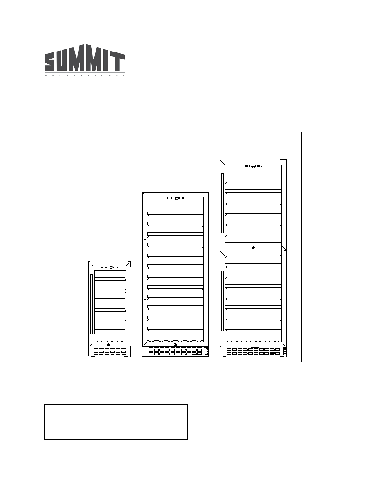
WINE CELLAR
INSTRUCTION MANUAL
Model Nos.: SWC1535B / SWC1102 / SWC1875B
BEFORE USE, PLEASE READ AND FOLLOW ALL SAFETY RULES AND OPERATING INSTRUCTIONS.
inside cabinet) here:
___________________________________________
770 Garrison Avenue
Bronx, NY 10474
www.summitappliance.com
Page 2

2
TABLE OF CONTENTS
Appliance Safety
3
Important Safeguards
3-4
Location of Parts
5-6
Installation Instructions
6-10
Before Using Your Appliance
6
Installation of Your Appliance
6-7
Built-in Cabinet Instructions
7
Electrical Connection
7
Extension Cord
8
Reversing the Door Swing of Your Appliance
8-10
Installing the Stainless Steel Handle
10
Operating Your Appliance
11-15
Recommended Temperature Settings
11
Control Panel for SWC1535B/SWC1102
11-12
Control Panel for SWC1875B
12-13
Interior Light
13
Sabbath Mode
13
Temperature Memory Function
13
Temperature Alarm / Door Alarm
14
Door Lock
14
Wine Shelves
14
Defrosting
14
Storage
14-15
Care and Maintenance
16
Cleaning Your Wine Cellar
16
Power Failure
16
Vacation Time
16
Moving Your Appliance
16
Energy Saving Tips
16
Troubleshooting
17-18
Limited Warranty
20
Page 3
3
APPLIANCE SAFETY
Your safety and the safety of others ar e very important.
We have provided many important safety messages in this manual and on your appliance. Always read
and obey all safety messages.
This is the Safety Alert Symbol. The symbol alerts you to potential hazards that
can kill or injure you and others. All safety messages will follow the Safety
Alert Symbol and either the words DANGER or WARNING.
DANGER means that failure to heed this safety
statement may result in severe personal injury or
death.
WARNING means that failure to heed this safety
statement may result in extensive product
damage, serious personal inj ury, or death.
All safety messages will alert you about the potential hazard, tell you how to reduce the chance of injury,
and let you know what can happen if the instructions are not followed.
IMPORTANT SAFEGUARDS
Before the appliance is used, it must be properly positioned and installed as
described in this manual, so read the manual carefully. To reduce the risk of fire,
electrical shock or injury when using the appliance, follow basic precautions,
including the following:
• Plug into a grounded 3-prong outlet, do not remove grounding pr o ng, do not use an adapter, and do
not use an extension cord.
• Replace all panels before oper ati ng.
• It is recommended that a separate circuit serving only your appliance be provided. Use receptacles
that cannot be turned off by a switch or pull chain.
• Never clean appliance parts with flamm able flu ids . T h es e f umes can create a f ir e ha zard or explosion.
And do not store or use gasoline or other flammable vapors and liquids in the vicinity of this or any
other appliance. The fumes can create a fire hazard or explosion.
• Do not connect or disconnect the electric plug when your hands are wet.
• Unplug the appliance or disconnect power before cleaning or servicing. Failure to do so can result in
electrical shock or death.
• Do not attempt to repair or replace any part of your appliance unless it is specifically recommended in
this manual. All other servicing should be referred to a qualified technician.
• This appliance is CFC- and HFC-free and contains small quantities of Isobutane (R600a) which is
environmentally friendly, but flammable. It does not damage the ozone layer, nor does it increase the
greenhouse effect. Care must be taken during transportation and setting up of the appliance that no
parts of the cooling system are damaged. Leaking coolant can ignite and may damage the eyes.
In the event of any damage:
Page 4

4
- Avoid open flames and anything that creates a spark,
- Disconnect from the electrical power line,
- Air the room in which the appliance is located for several minutes and
- Contact the Service Department for advice.
• The more coolant ther e is in an appliance, the l arger the r oom it sho uld be install ed in. In th e event of
a leakage, if th e appliance is in a sm all room, there is the d anger of com bustible gases building up.
For every ounce of coolant at least 325 cubic feet of room space is r equired. T he am ount of coolant in
the appliance is stated on t he data plate inside the a ppli ance. It is hazardous f or anyone other th an an
Authorized Service Person to carry out servicing or repairs to this appliance.
• Take serious care when handling, moving, and using the appliance to avoid either damaging the
refrigerant tubing or increasing the risk of a leak.
• Replacing component p arts and ser vicing sha ll be don e by factor y authorized ser vice per sonnel so as
to minimize the risk of possible ignition due to incorrect parts or improper service.
FOLLOW WARNING CALLOUTS BELOW ONLY WHEN APPLICABLE TO YOUR MODEL
• Use two or more people to move and install appliance. Failure to do so can result in back or other
injury.
• To ensure proper ventilation for your appliance, the front of the unit must be completely unobstructed.
Choose a well-ventilated area with temperatures above 60°F (16°C) and below 90°F (32°C). This unit
must be installed in an area protected from the elements, such as wind, rain, water spray or drips.
• The appliance should not be located next to ovens, grills or other sources of high heat.
• The appliance must be installed with all electrical, water and drain connections in accordance with
state and local codes. A standard electrical supply (115 V AC only, 60 Hz), properly grounded in
accordance with the National Electrical Code and local codes and ordinances, is required.
• Do not kink or pinch the power supply cord of the appliance.
• The size of the fuse (or circuit breaker) should be 15 amperes.
• It is important that the appliance be leveled in order to work properly. You may need to make several
adjustments to level it.
• All installations must be in accordance with local plumbing code requirements.
• Make certain that the pipes are not pinched, kinked or damaged during installation.
• Check for leaks after connection.
• Never allow children to operate, play with or crawl inside the appliance.
• Although the unit has been tested at the factory, due to long-term transit and storage, the first batch
of cubes must be discarded.
• Do not use solvent-based cleaning agents or abrasives on the interior. These cleaners may damage
or discolor the interior.
• Use this appliance only for its intended purpose as described in this Instruction Manual.
• Keep fingers out of the “pinch point” areas. Clearances bet ween t he doors and bet ween the door s
and cabinet are necessarily small. Be careful closing doors when children are in the area.
Risk of child entrapment!
Child entrapment and suffocation are not problems of the past. Junked or abandoned appliances are
still dangerous, even if they will “just sit for a few days”.
Before discarding your old refrigerator:
• Take off the doors
• Leave the shelves in place so that children may not easily climb inside.
- SAVE THESE INSTRUCTIO NS -
Page 5
5
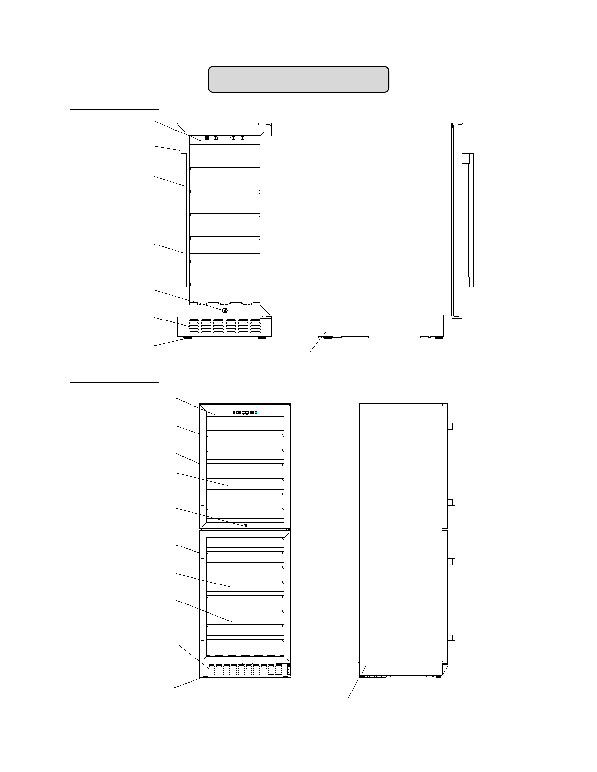
Door
Shelves(6)
Digital Control
Handle
Security
Lock
Panel
Cabinet
Adjustable
Legs
Ventilation
Grille
Upper Door
Shelves (14)
Digital Control
Adjustable
Legs
Handle
Security
Lock
Panel
Ventilation
Grille
Cabinet
Lower Door
Upper Zone
Lower Zone
MODEL SWC1535B
MODEL SWC1875B
LOCATION OF PARTS
Page 6
6
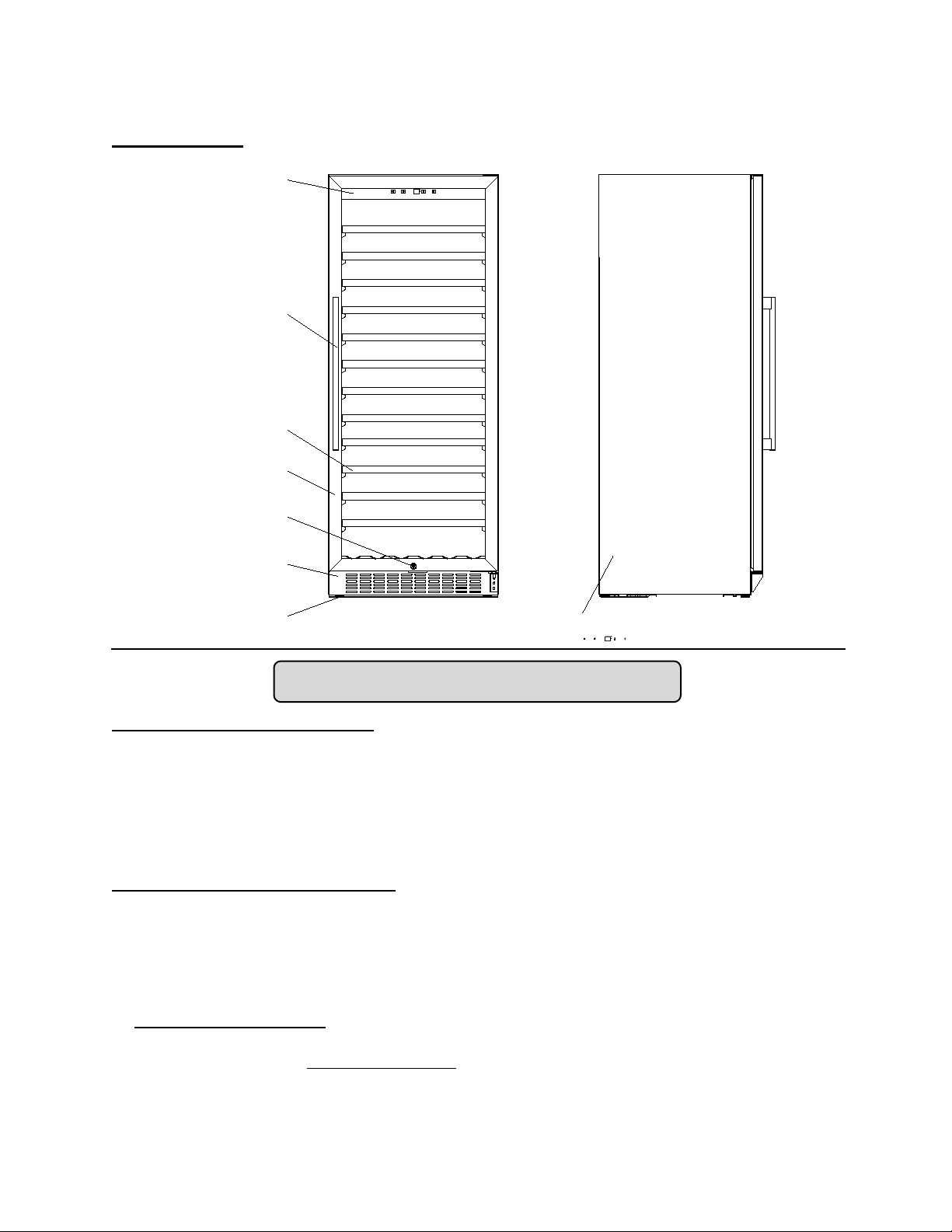
Adjustable Legs
Cabinet
Ventilation Grille
Shelves (12)
Door
Security Lock
Digital Control
Panel
Handle
MODEL SWC1102
INSTALLATION INSTRUCTIONS
BEFORE USING YOUR APPLIANCE
• Remove the exterior and interior packing.
• Before connect ing the appliance to the po wer source, let it stand upright for approx imately 2 hours.
This will reduce the possibility of a malfunction in the cooling system from handling during
transportation.
• Clean the interior surface with lukewarm water using a soft cloth.
• Install the handle on the door. (See page 10.)
INSTALLATION OF YOUR APPLIANCE
• The appliance is designed for built-in, recessed or free-standing insta ll ation.
• WARNING: Do not store or install the appliance outdoors.
• CAUTION
medicine or other medical products.
• Place your Wine Cellar on a floor that is strong enough to support it when it is fully loaded. To level the
unit, adjust the front adjustable legs.
•
For freestanding instal latio n, 5” (127mm) of spac e at the back and sides of the unit a nd 4“ (1 02mm ) at
the top are suggested, which allows the pr oper air circulation to c ool the compressor and conde nser
for energy saving. E ven
each side, 2” (50m m) at the back and 1/16” (1.6m m) at the top t o ensure proper service access and
ventilation. And the air vent at the front of the appliance must never be covered or blocked in any way.
: This appliance is designed for storing and cooling wines. Do not store per ishable food,
for built-in ins tallation, it is a m ust to keep at least 3/16” (5mm) of s pace on
Page 7
7
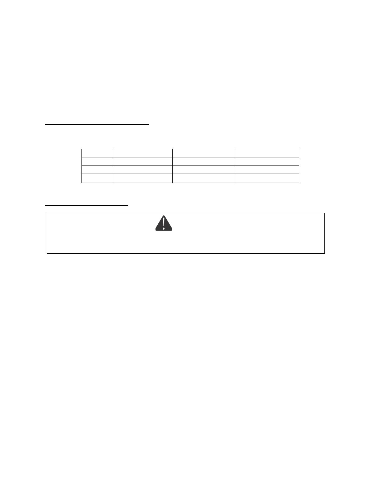
• NOTE: It is recom m ended that you do no t ins tall th e applianc e n ear an o ven, ra diator or ot her heating
Model
SWC1535B
SWC1102
SWC1875B
Width
15¾” / 40 cm
23.8” / 60.5 cm
23.8” / 60.5 cm
Depth
24¾” / 63 cm
24¾” / 63 cm
24¾” / 63 cm
Height
34¼” / 87 cm
58¼” / 148 cm
69⅞” / 177.5 cm
source. Direct sunlight may affect the acrylic coating and heat sources may increase electrical
consumption. Don’t install in a location where the temperature will fall below 60°F (16°C). For best
performance, do not install the appliance behind a cabinet door or block the base grille.
• Avoid locating the unit in moist areas.
• Plug the Wine Cellar into an exclusive, properly grounded wall outlet. Do not under any circum-
stances cut or rem ove the t hird (ground) prong f rom the power cord. Any quest ions conc erning po wer
and/or grounding should be directed toward a certified electrician or an authorized service center.
BUILT-IN CABINET INSTRUCTIONS
This unit is designed for either built-in or free-standing installation. If you plan to use the unit in a built-in
application, use the following dimensions for the enclosure:
ELECTRICAL CONNECTION
Improper use of the grounded plug can result in the risk of electrical shock. If the power cord is
damaged, have it replaced by a qualified electrician or an authorized service center.
This appliance should be properly grounded for your safety. The power cord of this appliance is equipped
with a three-prong pl ug which mates w ith standard three-prong wall outlets to minimize the poss ibility of
electrical shock.
Do not under any circumstances cut or remove the third (ground) prong from the power cord supplied. For
personal safety, this appliance must be properly grounded.
This appliance requires a standard 115/120 Volt AC 60Hz three-prong grounded electr ical outlet. Have
the wall outlet and circu it checked b y a qualified electric ian to make s ure the outlet is prop erly grounded.
When a standard 2-prong wall outlet is encountered, it is your responsibility and obligation to have it
replaced with a properly grounded 3-prong wall outlet.
To prevent accidental injur y, the cord should be secured behin d the appliance and not left exposed or
dangling.
The appliance shoul d a l ways be plugged into its own i ndi vidua l electrical out let whic h has a voltage rat ing
that matches the rating label on the appliance. This provides the best performance and also prevents
overloading house wiring circuits that could cause a fire hazard from overheating. Never unplug the
appliance by pulling on the power cord. Always grip the plug firmly and pull straight out from the
receptacle. Repair or replace immediately all power cords that have become frayed or otherwise
damaged. Do not use a cord that shows cracks or abrasion damage along its length or at either end.
When moving the appliance, be careful not to damage the power cord.
WARNING
Page 8
8
EXTENSION CORD
Because of potential safety hazards under certain conditions, it is strongly recommended that you do not
use an extension cord with this appliance. However, if you must use an extension cord it is absolutely
necessary that it be a UL/CUL-Listed, 3-wire grounding type appliance extension cord having a grounding
type plug and outlet and that the electrical rating of the cord be 115 volts and at least 10 amperes.
REVERSING THE DOOR SWING OF YOUR APPLIANCE
This unit has the capability of the door opening from either the left or right side. The unit is delivered to
you with the door opening from the left side. Should you desire to reverse the opening direction, pl eas e
follow the reversal instructions shown below.
NOTE: All parts removed must be saved to allow the door swing to be reversed.
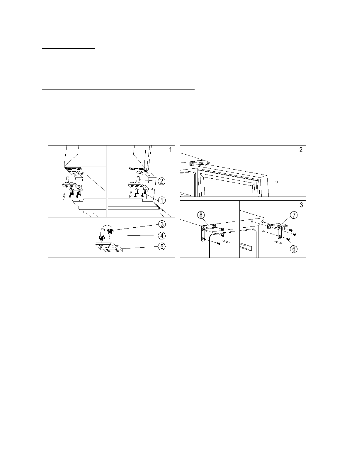
Model SWC1535B
1. Remove the bottom hinge 2 by unsc rewing the four l ock screws 1. Be careful to hold t he door firmly
after removing the screws. (Fig. 1)
2. Gently pull down to r emove the door from the right top hing e and place it on a padded surface to
avoid the risk of damage. Then remove the right top hinge 7. (Fig. 2 & 3)
3. Unscrew and transfer pins 4 and 3 of the hinge plate to the opposite side. (Fig. 1)
4. Pop out the cover c aps on the lef t side of c abinet and use them t o cover the scre w holes on th e right
hand side.
5. Screw the alternative left top hinge 8, included in the fittings, on the left hand side of cabinet. (Fig. 3)
6. Relocate the door to the designated position. Then screw the bottom hinge assembly on the left
designated position and tighten it after the door is leveled. (Fig. 1)
7. Remove the handle from the left side of the door and install it on the right side. (See page 10.)
Page 9
9
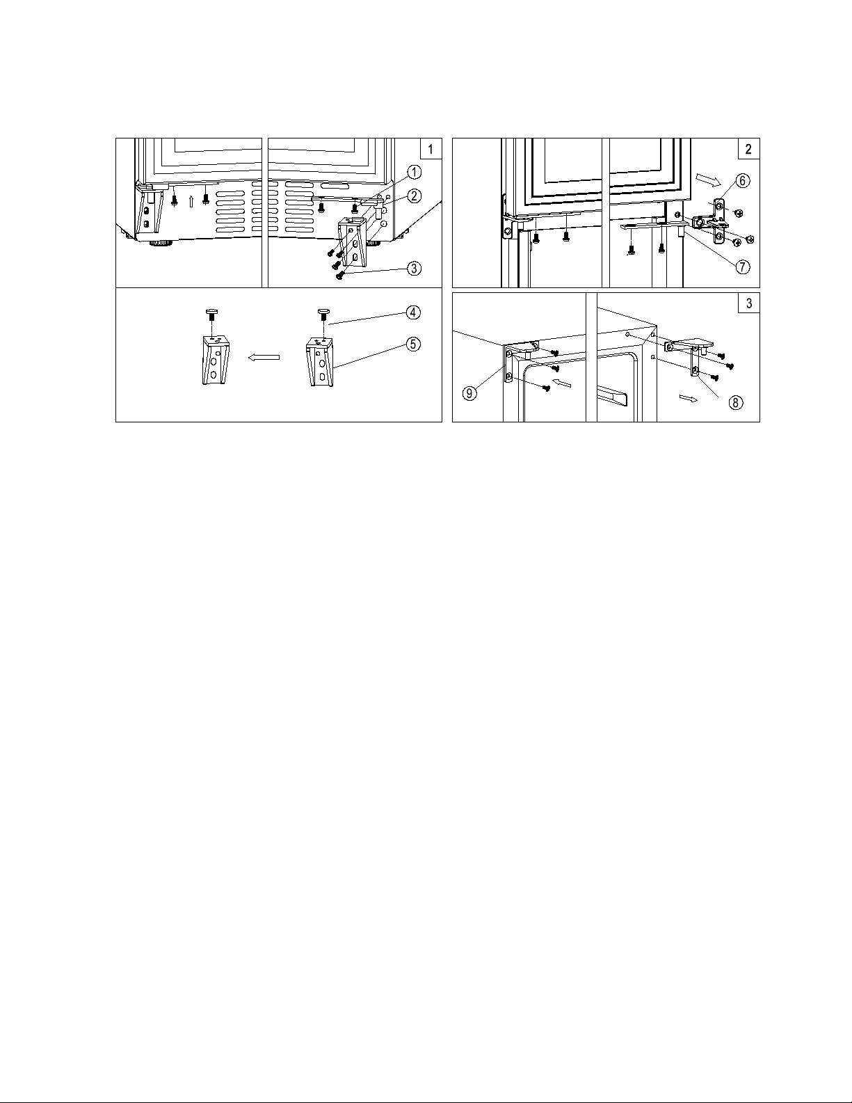
Model SWC1875B
1. Remove the lower do or sh aft as sem bly 2 by unscrewing the two lock screws 1. Be caref ul to ho ld the
lower glass door firmly after removing the screws. And then gently pull down to remove the lower
glass door from the middle hinge and place it on a padded surface to avoid the risk of damage. (Fig. 1)
2. Remove the upper d oor shaft assem bly 7 by unscrew ing the two lock screws. Be c areful to hold t he
upper glass door firm ly after removing t he screws. And then gently pull down to remove the upper
glass door from the top hinge and place it on a padded surface to avoid the risk of damage. (Fig. 2)
3. Unscrew and remove the middle hinge 6 and the right top hinge 8. (Fig. 2 & 3)
4. Pop out the cover c aps on the lef t side of c abinet and use them t o cover the scre w holes on th e right
hand side.
5. Screw the m iddle hinge 6 and the a lternative left top hin ge 9 included in the fitti ngs, on the left hand
side of cabinet. (Fig. 2 & 3)
6. Unscrew and transf er the lower hinge bracket 5 to the opposite side. At the sam e time remove the
stopper pin 4 to the opposite designated position of the lower hinge bracket. (Fig. 1)
7. Relocate the upper and lower door shaft assembly to the designated positions.
8. Set the upper glass door to the designa ted position and install the t wo lock screws to connect the
upper door shaf t assembly 7 with the upper glass door and tighten them befor e the door is leveled.
(Fig. 2)
9. Set the lower glass door to the designated posi tion and install the two lock screws 1 to connec t the
lower door shaft as sembly 2 with the lower glass door and ti ghten them before the door is leveled.
(Fig. 1)
10. Remove the handles from the left side of the doors and install them on the right side. (See page 10.)
Page 10
10
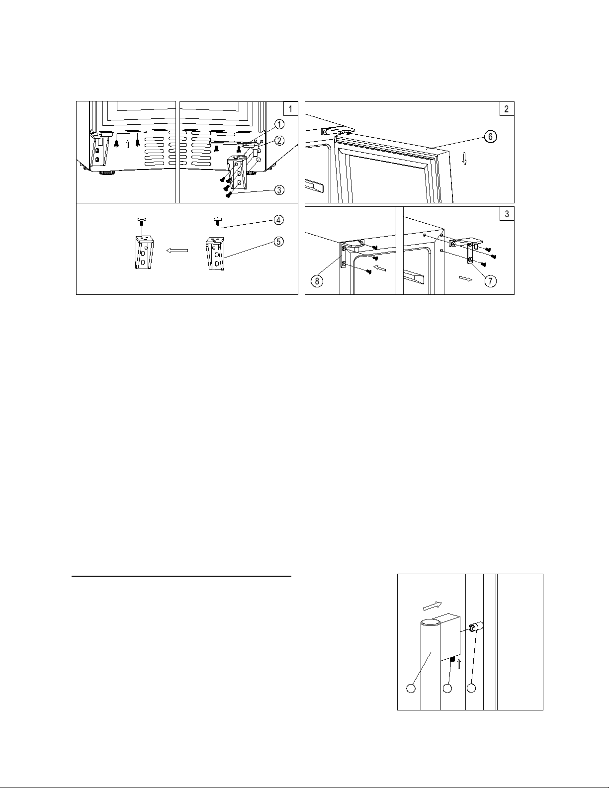
Model SWC1102
1
2
3
1. Remove the door shaft assem bly 2 by unscrewing th e two lock scr ews 1. Be car eful to hold th e glass
door firmly after removing the screws. (Fig. 1)
2. Gently pull down to remove the glass door f rom the right top hinge an d p lace it on a padded surface to
avoid the risk of damage. Then remove the right top hinge 7. (Fig. 2 & 3)
3. Pop out the cover ca ps on the lef t side of cabinet and use them to cover the s crew holes on the right
hand side.
4. Screw the alternative left top hinge 8, included in the fittings, on the left hand side of cabinet. (Fig. 3)
5. Unscrew and transf er the lower h inge bracket 5 and door suppor ter to the op posite side. At the same
time remove the stopper pin 4 to the opposite designated position of the lower hinge bracket. (Fig. 1)
6. Relocate the door shaft assembly to the designated position.
7. Relocate the glass do or to the designated position. Then scre w the door shaft assembly on the lef t
designated position and tighten it after the door is leveled. (Fig. 1)
8. Remove the handle from the left side of the door and install it on the right side. (See below.)
INSTALLING THE ST AINL ES S STEEL HANDLE
This appliance includes a stainless steel handle that is not required to
operate the unit. To install the handle, follow the instructions below:
Locate the handle 1 over the pins 3 of the door and tighten the handle
by screwing in screws 2 with an Allen wrench .
Page 11
11
Conservation
49 ~ 57ºF
10 ~ 14ºC
Red Wines
58 ~ 72ºF
15 ~ 22ºC
Dry/White Wines
48 ~ 57ºF
9 ~ 14ºC
Rosé Wines
49 ~ 51ºF
10 ~ 11ºC
Sparkling Wines
41 ~ 47ºF
5 ~ 8ºC
OPERATING YOUR APPLIANCE
It is recommended you install the appliance in a place where the ambient temperature is between 72º and
78ºF (23º-26ºC). If the ambient temperature is above or below the recommended temperatures, the
performance of the unit may be affected. For example, placing your unit in extreme cold or hot conditions
may cause interior temperatures to fluctuate. The range of 41º-72ºF (5º-22ºC) may not be reached.
RECOMMENDED TEMPERATURE SETTINGS
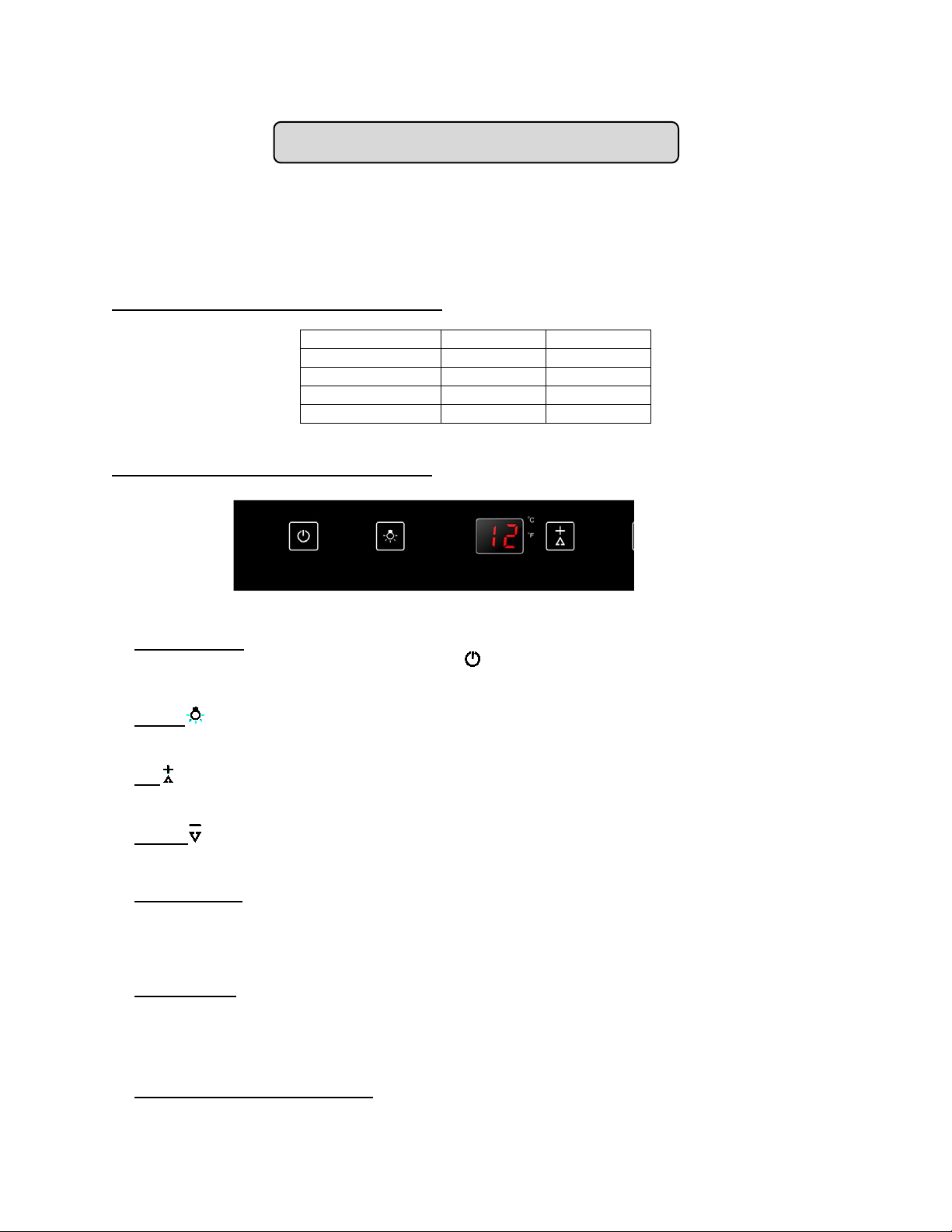
CONTROL PANEL for SWC1535B/SWC1102
ON/OFF Power
To turn the appliance ON or OFF, touch the symbol and hold for 5 seconds.
NOTE: Pressing the POWER key once can switch off the audible alarm when the alarm is on.
LIGHT
Turn the interior light on and off with this switch.
UP
Used to increase (warm) the set temperature by 1°C/1ºF.
DOWN
Used to decrease (cool) the set temperature by 1°C/1ºF.
Indicator Light
The indicator light is located at the right lower corner of the display. The indicator light will be on
when the multi-key function is selected. To perform the multi-key function, press and hold the first
key, then press the rest key for at least 5 seconds and then release all the keys
ºF/ºC Selector
Select the temperature display setting in Fahrenheit or Celsius degree. To change the temperature
from Fahrenheit to Celsius or from Celsius to Fahrenheit, press and hold the LIGHT key for 5
seconds.
Setting the Temperature Control
• You can set the temperature by touching the UP and DOWN symbols. When you push the two
.
Page 12
12
buttons at the same time, the LED readout will show the original temperature set previously.
(The temperature preset at the factory is 54°F or 12°C.)
• The temperature you are setting will increase by one degree each time you touch the UP
symbol, and will decrease by one degree each time you touch the DOWN symbol.
• The range of the temperature control is from 41°F to 72°F.
• To view the set temperature at any time, touch the UP or DOWN symbol. The set temperature
will flash in the display window for 5 seconds. After 5 seconds, the temperature inside the unit
will reappear in the display window.
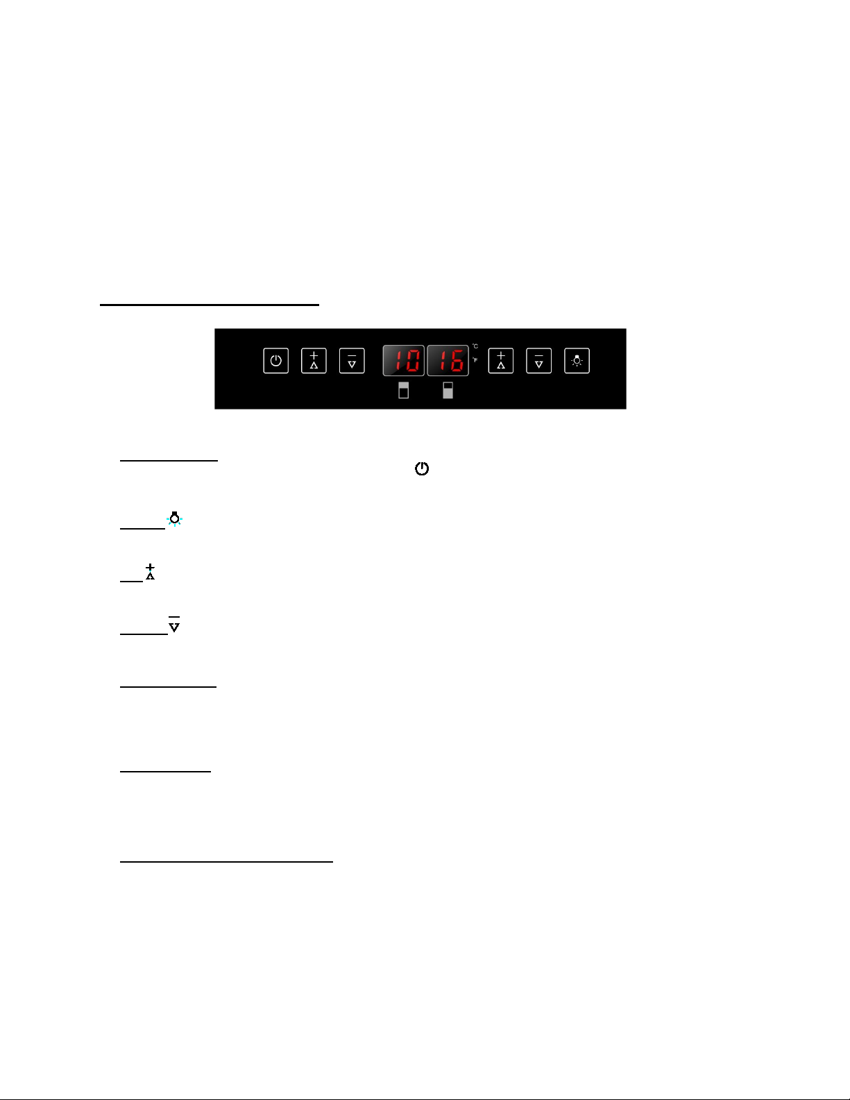
CONTROL PANEL for SWC1875B
ON/OFF Power
To turn the appliance ON or OFF, touch the symbol and hold for 5 seconds.
NOTE: Pressing the POWER key once can switch off the audible alarm when the alarm is on.
LIGHT
Turn the interior light on and off with this switch.
UP
Used to increase (warm) the set temperature by 1°C/1ºF.
DOWN
Used to decrease (cool) the set temperature by 1°C/1ºF.
Indicator Light
The indicator light is located at the right lower corner of the display. The indicator light will be on
when the multi-key function is selected. To perform the multi-key function, press and hold the first
key, then press the second key for at least 5 seconds and then release all the keys
.
ºF/ºC Selector
Select the temperature display setting in Fahrenheit or Celsius degree. To change the temperature
from Fahrenheit to Celsius or from Celsius to Fahrenheit, press and hold the LIGHT key for 5
seconds.
Setting the Temperature Control
• The unit has two separate temperature zones. The temperature of both zones can be set
between 41ºF and 72ºF (5ºC and 22ºC). The LOWER temperature zone is ideal for storing
white and red wine at a setting of 55°F to 72°F (13°C to 22°C). The UPPER temperature zone is
suitable for storing champagne and white wine at a setting of 41°F to 55°F (5°C to 13°C).
• When the unit is plugged in for the first time, the unit will power up automatically to the preset
defaults. The preset temperature at the factory for the UPPER temperature zone is 50ºF (10ºC)
and for the LOWER temperature zone is 60ºF (16ºC).
Page 13
13
• You can press the left side UP and DOWN keys to control the internal temperature of the
UPPER temperatur e zone and press the right side UP and DOWN keys to control the internal
temperature of the LOWER temperatur e zone . When you press the two keys at the same time,
the display will show the last temperature set previously.
• NOTE: The temperature set for the LOWER temperature zone must always be just as high
as or higher than that in the UPPER temperature zone. For o p timal performance, the set
temperature of the two zones should differ by at least 8°F.
• The temperature that you desire to set will increase 1ºC or 1ºF if you press the UP key once; on
the contrary the temperature will decrease 1ºC or 1ºF if you press the DOWN key once. The
display flashes while you make the setting.
• After the temperature has been set, the display shows the current inner temperature of the
particular temperature zo ne.
• To view the set temperature at any time, press the UP or DOWN key; the set temperature will
temporarily flash in the display for 5 seconds. Then the display shows the current inner
temperature again.
INTERIOR LIGHT
The interior light makes it easy to view your wine labels and enhances the display of your collection. The
LIGHT switch allows you to toggle between 2 modes of operation for the internal lights: functional
(default) mode and showcase mode. If you are in functional (default) mode (also named as energy saving
mode), the lights will turn on only when the door is open. If you are in showcase mode, the lights will be
on whether or not the door is open.
SABBATH MODE
Sabbath mode is available for the observance of certain religious holidays. This mode turns off the
displays, interior light and audible alarms and prevents them from turning on again. Normal cooling
operations will still take place.
To initiate Sabbath mode, press the POWER and LIGHT keys at the same time for at least 5 seconds.
The indicator light will flash four times and confirm the Sabbath mode is ON.
Sabbath mode can be exited by repeating the a bove process. T he Sabbath Mode will automatic ally turn
off after 96 hours.
TEMPERATURE MEMORY FUNCTION
In the event of a power interruption (power surge, breaker switch, etc.), the unit will remember the
previous temperature settings, and when the power is recovered, the cabinet temperature will return to
the same setting as before the power went off.
NOTE:
• If the unit is unplugged, or power is lost or turned off, you must wait 3 to 5 minutes before
restarting the unit. If you attempt to restart before this time delay, the unit will not start.
• When you use the unit for the first time or restart the unit after it has been shut off for a long
time, there could be a few degrees variance between the temperature you select and the one
indicated on the LED readout. This is normal and is due to the length of the activation time.
There should not be a problem once the unit has been running for a few hours.
Page 14
14
TEMPERATURE AL ARM / DOOR ALARM
• The audible alarm sounds if the storage temperature is not cold enough. The temperature display
flashes at the same time.
• The cause of the temperature being too high may be:
– Warm fresh items were placed inside
– Too much warm ambient air flowed in when rearranging and removing food
– Power failure for some time
– The appliance is faulty
• The audible alarm is automatically silenced and the temperature display stops flashing when the
temperature is sufficiently cold again.
• If the door has been left open for more than 60 seconds, the alarm will sound. Pressing the POWER
key once will switch off the audible alarm.
DOOR LOCK
Your unit is provided with a lock and key combination.
The keys are located inside the plastic bag that contains the Instruction Manual. Insert the key into the
lock and turn it counterclockwise to unlock the door. To lock the door, do the reverse operation, making
sure the metal pin is engaged completely. Remove the key and place it in a secure place for safekeeping.
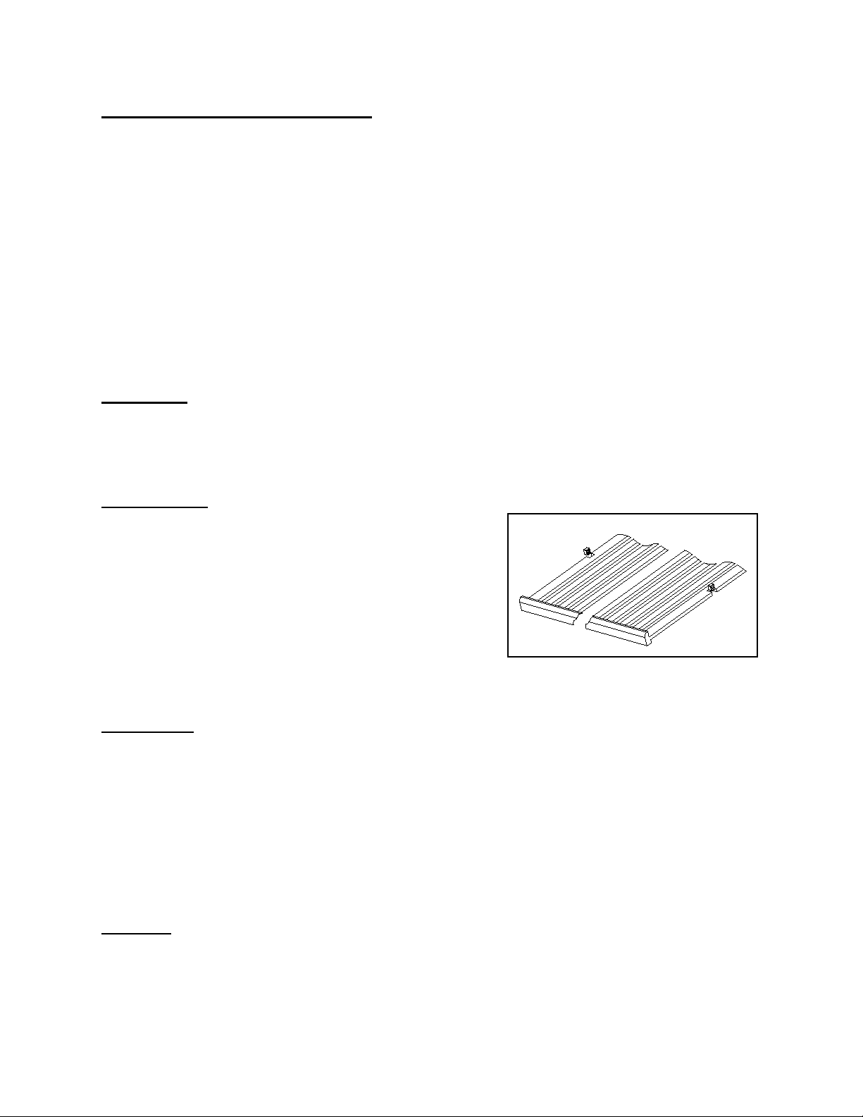
WINE SHELVES
To prevent damaging the door gasket, make sure to have the
door all the way open when pulling the shelves out of the rail
compartment.
• For easy access to the stored bottles, you can pull the
shelf approximately halfway out of the rail compartment.
However this unit was designed with a plastic post on each
side of the shelf track to prevent bottles from falling.
• When removing the wooden shelf from the inner rails,
make sure to remove all bottles first. Then move the shelf
to the position where the notches in the wooden shelf are exactly aligned with the plastic posts and lift
the wooden shelf. In order to replace the shelf, repeat this procedure in reverse.
DEFROSTING
• The unit defrosts automatically in normal operating conditions.
• The evaporator behind the rear wall of the unit defrosts automatically. The condensate collects in the
drainage channel behind the rear wall of the unit, and flows through the drainage hole into the drip tray
by the compressor where it evaporates.
• However, frost may accumulate on the evaporator if the unit is repeatedly opened in a high heat or high
humidity location. If this frost pattern does not clear within 24 hours, your unit will require manual
defrosting.
STORAGE
Bottles can differ in size. Accordingly, the actual number of bottles you can store may vary.
The approximate maximum bottle capacity can be achieved when storing traditional Bordeaux 750 ml
bottles in bulk storage.
Page 15

15
You may load your wine bottles in single rows or by stacking while taking note of the following: if you do
not have enough bottles to fill your wine cellar, it is better to distribute the load throughout the wine cellar
so as to avoid “all on top” or “all below” type loads.
- Do remove or reloc at e a dj u s table wooden shelves to a c c ommodate larger type of bott les or i nc reas e
the capacity of the cellar by stack ing the bottles up when neces sary. (See instructions for removing
shelves, above.)
- Keep small gaps b etween the walls and the bo ttles to allow air to circulate. As in an underground
cellar, air c irculation is important to prevent m old and for a more homogeneous tem perature within
the cellar.
- To facilitate air circulation, do not overload your wine cellar.
- Avoid obstructing the internal fans (located inside on the rear panel of the wine cellar).
- To prevent bottles from falling, do not try to slide the shelves outward beyond the fixed position.
- Do not pull out more than one load ed shelf at a tim e as this m ay cause the w ine cellar t o tilt for ward
if not properly installed.
Page 16
16
CARE AND MAINTENANCE
CLEANING YOUR WINE CELLAR
• Turn off the power, unplug the appliance, and remove all items, including shelves.
• Wash the inside surfaces with a solution of warm water and baking soda (about 2 tablespoons of
baking soda to a quart of water).
• Wash the shelves with a mild detergent solution.
• Wring excess water out of t he s pon ge or c lot h when c l ean ing the area where the controls are loc ate d,
or any electrical parts.
• Wash the outside cabin et with warm water and mild liquid deterge nt. Rinse well and wipe dry with a
clean soft cloth.
• Do not use steel wool or a steel brush on the stainless steel.
CAUTION:
Failure to unplu g the appliance during cleaning could result in electrical shock or other personal injury
POWER FAILURE
Most power failures are corrected within a few hours and should not affect the temperature of your
appliance if you m inimize the number of times the do or is opened. If the power is go ing to be off for a
longer period of time, you need to take the proper steps to protect the contents.
VACATION TIME
• Short vacations: Leave the appliance operating during vacations of less than three weeks.
• Long vacations: If the appliance will not be used for several m onths, remove all items and tur n off
the appliance. Clean and dry the interior thoro ughly. To prevent odor and m old growth, leave the
door open slightly, blocking it open if necessary.
MOVING YOUR APPLIANCE
1. Remove all items.
2. Securely tape down all loose items (shelves) inside your appliance.
3. Turn the adjustable legs up to the base to avoid damage.
4. Tape the door shut.
5. Be sure the appliance stays secure in the upright position during transportation. Also, protect the
outside of the appliance with a blanket or similar item.
ENERGY SAVING TIPS
• The appliance should be located in the coolest area of the room, away from heat-producing
appliances and out of direct sunlight.
• Ensure that the unit is adequately ventilated. Never cover air vents.
• Do not keep the door open any longer than necessary.
.
Page 17
17
TROUBLESHOOTING
PROBLEM
POSSIBLE CAUSE
REMEDY
fuse.
dusty.
dust.
replace.
panel.
Switch on the light.
adjustable feet.
The rattling noise may come from the flow of the refrigerant, which is normal. As each
cause popping and cracking noises.
adjustable feet.
installed.
correctly.
You can solve many common problems easily, saving you the cost of a possible service call. Try the
suggestions below to see if you can solve the problem before calling the servicer.
Troubleshooting Guide
Appliance
does not
operate.
Appliance is
not cold
enough.
Appliance
turns itself on
and off
frequently.
• Appliance is not connected to a power
supply.
• The appliance is turned off.
• Tripped circuit breaker or a blown fuse.
• The temperature is not set correctly.
• The ambient temperature could require
a lower temperature setting.
• The door was opened too often.
• The door was not closed completely.
• Door is not hermetically sealed.
• The condenser is too dirty.
• The ventilatio n ope ni ng is b loc ked or too
• The room temperature is higher than
average.
• A large number of bottles has been
added to the unit.
• The door is open too often.
• The door is not closed completely.
• The door gasket does not seal properly.
• Connect the appliance.
• Switch on the appliance.
• Switch on circuit breaker or replace
• Check the set temperature.
• Set a lower temperature.
• Do not open the door more often than
necessary.
• Close door properly.
• Check the door seal and clean or
replace.
• Clean the condenser when necessary.
• Clear the obstructions and clean the
• Put the appliance in a cooler place.
• Leave the appliance to work for a
while until the set temperature has
been reached.
• Do not open the door more often than
necessary.
• Close door properly.
• Check the door seal and clean or
• Appliance is not connected to a power
The light does
not work.
Vibrations
The appliance
seems to
make too
much noise.
The door will
not close
properly.
supply.
• Tripped circuit breaker or a blown fuse.
• The light was switched off on the control
• The appliance is not properly level.
cycle ends, you may hear gurgling sounds caused by the flow of refrigerant in your
appliance.
If temperature fluctuations occur, the contraction and expansion of the inner walls may
• The appliance is not properly level. • Level the appliance with the
• The appliance is not properly level.
• The door was reversed and not properly
• Connect the appliance.
• Switch on circuit breaker or replace
fuse.
•
• Level the appliance with the
• Level the appliance with the
adjustable feet.
• Check the door hinge and reassemble
Page 18

18
The shelves are out of position.
Check the shelves and refit correctly.
Display “E0”,
“E7” indicates the door switch failure.
Has the appliance door been open for
added to the unit.
If yes, close the door.
“E1”. “E2”,
“E3”, “E4”,
“E5” or “E7”.
• The gasket is dirty.
•
• “E0” indicates the communication error
for 3 zone models.
• “E1” or “E2” indicates that the air
temperature sensor has failed.
• “E3” or “E4” indicates that the defrost
sensor in the evaporator has failed.
• “E5” indicates the defrost heater failure.
•
• Clean the door gasket.
•
• Call for service.
The alarm
sounds and
the
temperature
display
flashes.
The icon “--”
is lit up and
flashing in the
temperature
display.
longer than 60 seconds? If not, then the
temperature has risen higher or fallen
lower than the temperature that has been
set. This could be due to:
• The appliance door being opened too
often.
• The ventilation opening being covered
or too dusty.
• A lengthy interruption to the power
supply.
• A large number of bottles has been
• The display temperature is out of range. • Only temperatures within the range
• Do not open the door more often than
necessary.
• Clear the obstructions and remove the
dust.
• Leave the appliance to work for a
while until the set temperature has
been reached.
0~99°F/-9~37°C can be displayed. If
the temperature is not within this
range, the icon “--” will be displayed
instead. This is normal.
Page 19

19
NOTES
Page 20
20
LIMITED WARRANTY
FELIX STORCH, INC.
For parts and accessory ordering,
ONE-YEAR LIMITED WARRANTY
Within the 48 contig uous United States, for on e year from the date of purchas e, when this appliance is
operated and maintained a c c ording to ins truc ti ons atta c hed to or f ur nishe d with the product, warrantor wil l
pay for factory-specif ied parts and repair labor to correct def ects in materials or workmanship. Ser vice
must be provided by a des ignated service company. Outside the 48 s tates, all parts are warranted for
one year from manufacturing defects. Plastic parts, shelves and cabinets are warranted to be
manufactured to comm ercially acceptable standards , and are not covered from damage dur ing handling
or breakage.
5-YEAR COMPRESSOR WARRANTY
1. The compressor is covered for 5 years.
2. Replacement does not include labor.
ITEMS WARRANTOR WILL NOT PAY FOR:
1. Service calls to correct the installation of your appliance, to instruct you how to use your appliance, to
replace or repair fuses or to correct wiring or plumbing.
2. Service calls to repair or replace appliance light bulbs or broken shelves. Consumable parts (such as
filters) are excluded from warranty coverage.
3. Damage resulting from accident, alteration, misuse, abuse, fire, flood, acts of God, improper
installation, installation not in accordance with electrical or plumbing codes, or use of products not
approved by warrantor.
4. Replacement parts or repair labor costs for units operated outside the United States.
5. Repairs to parts or systems resulting from unauthorized modifications made to the appliance.
6. Expenses for travel and transportation for product service in remote locations.
7. The removal and reinstallation of your appliance if it is installed in an inaccessible location or is not
installed in accordance with published installation instructions.
DISCLAIMER OF IMPLIED WARRANTIES;
LIMITATION OF REMEDIES
CUSTOMER'S SOLE AND EXCLUSIVE REMEDY UNDER THIS LIMITED WARRANTY SHALL BE
PRODUCT REPAIR AS PROVIDED HEREIN. IMPLIED W ARRANTIES, INCLUDING WARRANTIES OF
MERCHANTABILITY OR FITNESS FOR A PARTICULAR PURPOSE, ARE LIMITED TO ONE YEAR.
WARRANTOR SHALL NOT BE L IABLE FOR INCID ENTAL OR CONSEQU ENTIAL DAMAGES. SOME
STATES DO N OT ALL OW THE EX CLUSIO N OR LIMIT ATION OF INCI DENT AL O R CONS EQUEN TIAL
DAMAGES, OR LIMITATIONS ON THE DURATION OF IMPLIED WARRANTIES OF
MERCHANTABI LIT Y OR F ITNESS, SO T HESE EXCL USION S OR LI MITAT IONS M AY NO T A PPLY T O
YOU. THIS WAR RANTY GIVE S YOU SPEC IFIC LEG AL RIGHTS AN D YOU MA Y ALSO HAVE O THER
RIGHTS, WHICH VARY FROM STATE TO STATE.
770 Garrison Avenue
Bronx, NY 10474
Phone: (718) 893-3900
Fax: (718) 842-3093
www.summitappliance.com
troubleshooting and helpful hints, visit:
www.summitappliance.com/support
Printed in China
 Loading...