

Summit SMB-200, SMB-250, SMW-200, SMW-250 Installation, Operating And Maintenance Instructions
Page 1
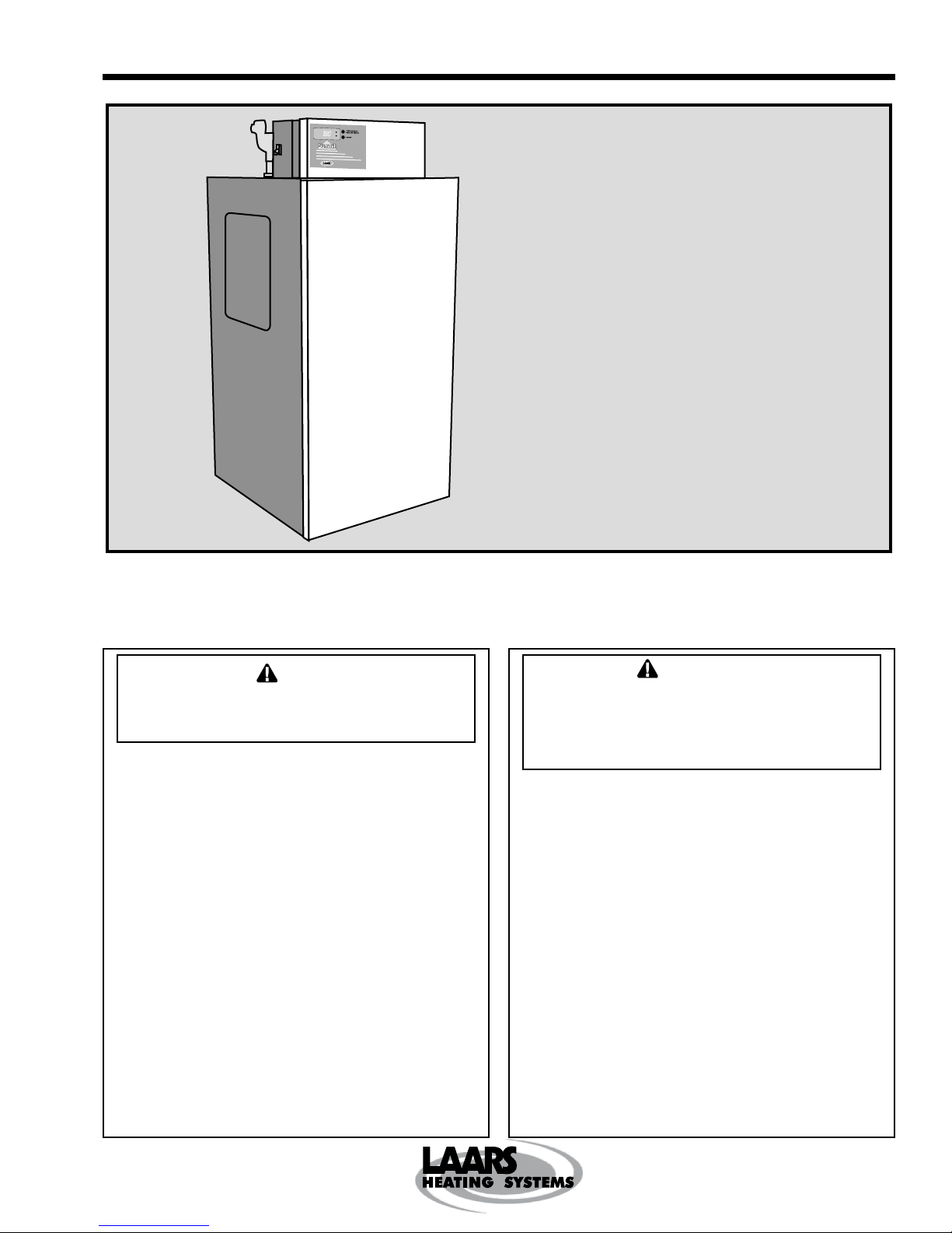
Installation, Operating and Maintenance Instructions Document 1163D
Installation,
Operation and
Maintenance
Instructions for
SUMMIT
Condensing Modulating Boiler
Models SMB-200, SMB-250
Condensing Modulating Water Heater
Models SMW-200, SMW-250
FOR YOUR SAFETY: This product must be installed and serviced by a professional service technician,
qualified in hot water boiler and heater installation and maintenance. Improper installation and/or
operation could create carbon monoxide gas in flue gases which could cause serious injury, property
damage, or death. Improper installation and/or operation will void the warranty.
If the information in this manual is not followed
WARNING
exactly, a fire or explosion may result causing
property damage, personal injury or loss of life.
Do not store or use gasoline or other flammable
vapors and liquids in the vicinity of this or any other
appliance.
WHAT TO DO IF YOU SMELL GAS
• Do not try to light any appliance.
• Do not touch any electrical switch; do not use
any phone in your building.
• Immediately call your gas supplier from a nearby
phone. Follow the gas supplier's instructions.
• If you cannot reach your gas supplier, call the fire
department.
Installation and service must be performed by a
qualified installer, service agency, or gas supplier.
To the Installer: After installation these instructions must
be given to the homeowner or left on or near the appliance.
To the User: This booklet contains important information
that will help you in maintaining and operating this heater.
Please retain it for future reference.
Assurez-vous de bien suivres les instructions
données dans cette notice pour réduire au
minimum le risque d’incendie ou d’explosion ou
pour éviter tout dommage matériel, toute blessure
ou la mort.
Ne pas entreposer ni utiliser d’essence ni d’autres
vapeurs ou liquides inflammables dans le voisinage
de cet appareil ou de tout autre appareil.
QUE FAIRE SI VOUS SENTEZ UNE ODEUR DE GAZ:
• Ne pas tenter d’allumer d’appareils.
• Ne touchez à aucun interrupteur. Ne pas vous
servir des téléphones dansle bâtiment où vous
vous trouvez.
• Appelez immédiatement votre fournisseur de gaz
depuis un voisin. Suivez les instructions du
fournisseur.
• Si vous ne pouvez rejoindre le fournisseur de
gaz, appelez le sservice des incendies.
L’installation et l’entretien doivent être assurés par un
installateur ou un service d’entretien qualifié ou par le
fournisseur de gaz.
À l’installateur : Après l’installation, ces instructions
doivent être remises au propriétaire de la maison ou
demeurer près de l’appareil.
AVERTISSEMENT
H2212100D
Page 2

Page 2
Table of Contents
SECTION 1.
General Information
1.1 Introduction...................................................3
1.2 Warranty.......................................................4
1.3 Materials Installer Must Provide.................... 4
1.4 Unpacking.....................................................4
1.5 Locating the SUMMIT Appliance................... 4
1.6 Locating Appliance for Correct
Vent Dist ance from Out side Wall or
Roof Termination ..........................................5
1.7 Locating Appliance for Proper Vent Height.... 5
1.8 Locating Appliance with Respect
to Ventilation ................................................. 5
1.9 Locating SUMMIT Water Heater with
Respect to StorageTank(s) ........................... 5
1.10 Locating SUMMIT Boiler with Respect to
Supply/Return Header .................................. 5
SECTION 2.
Ventilation
2.1 Locating V ent Openings on Out side Wall ...... 6
2.1.1 Exhaust T erminal Location............................ 6
2.1.2 Intake Terminal Location ............................... 6
2.2 Installing V ent Piping / Terminals ..................6
SECTION 3.
Gas Connections
3.1 Gas Supply and Piping ................................. 7
SECTION 4A.
Water Connections
SMB-200/250 Boiler
4A.1 Heating System Piping:
Hot Supply Connections ............................... 8
4A.2 Return Connections .................................... 10
4A.3 Cold Water Makeup....................................10
SECTION 4B.
Water Connections
SMW-200/250 Water Heater
4B.1 Water System Piping, Fittings
and Accessories ......................................... 10
4B.2 Combined Water (potable) Heating and
Sp ace Heating (SMW-200/250 Only)..........13
SECTION 4C.
Condensate Drain Connection
................................................................... 13
SECTION 5.
Electrical Connections
5.1 Main Power................................................. 14
5.2 Temperature Control – SMB-200/250 ......... 15
5.3 Temperature Control – SMW-200/250 ........ 15
5.3.1 Water Heater Temperature Control ............. 15
5.3.2 Tank Temperature Control .......................... 15
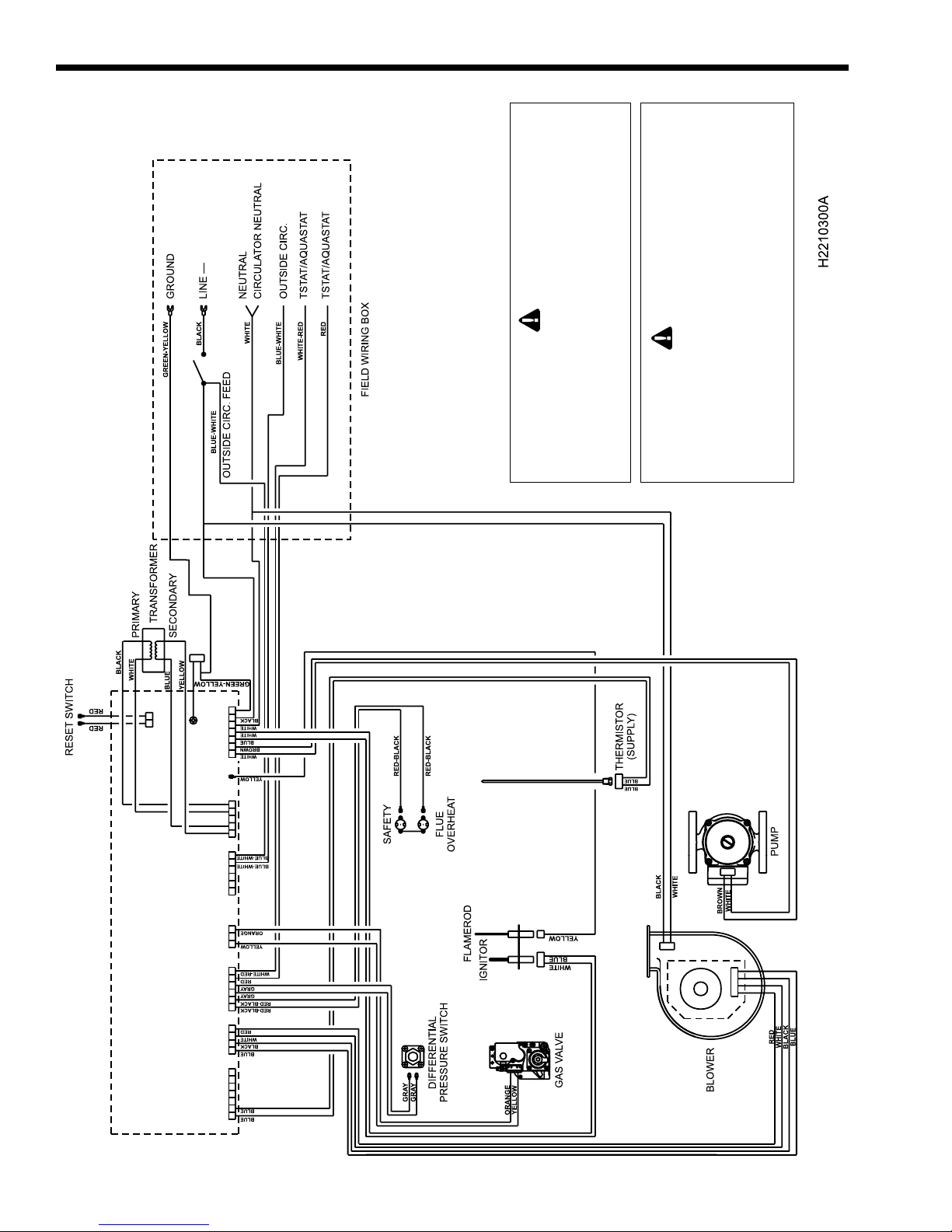
5.4 Wiring Diagram........................................... 15
LAARS HEATING SYSTEMS
SECTION 6.
Operating Instructions
Warning Label ............................................18
6.1 Anti-Freeze ................................................. 19
6.1.1 Summit Boiler Low Temperature Feature.... 19
6.1.2 Anti-Freeze Boiler Additives........................19
6.2 Anti-Freeze SMW-200/250 Water Heater ... 19
6.3 Filling the System ....................................... 19
6.4 Operating the Burner and Set Up................ 20
6.5 Mode and On/Off Buttons Operation........... 21
6.6 Common Vent Test ..................................... 21
SECTION 7.
Maintenance
7.1 System Maintenance .................................. 22
7.2 Appliance Maintenance and
Component Description .............................. 23
7.2.1 Appliance Pump ......................................... 23
7.2.2 Gas V alve ................................................... 23
7.2.2.1 Offset and Throttle Adjustment ................... 23
7.2.3 Safety Limit Switch ..................................... 24
7.2.4 Appliance Control, Printed Circuit
Board (PCB ................................................ 24
7.2.5 Ignitor / Flame Sensor Assembly ................24
7.2.6 Transformer................................................24
7.2.7 Blower ........................................................ 24
7.2.8 Mixing V alve................................................ 24
7.2.9 Cleaning the Primary Heat Exchanger Coil. 25
7.2.10 Burner......................................................... 25
7.2.1 1 Vent Terminals ............................................ 25
7.2.12 Condensate Collection System –
Inspection and Cleaning ............................. 25
7.2.13 Routine Deliming Procedure –
SMW-200/250.............................................25
SECTION 8.
Trouble Shooting
8.1 Sequence of Operation...............................26
8.2 Trouble Shooting Fault Codes .................... 26
8.3 Fault Code Identification ............................. 26
8.4 Fault Correction .......................................... 26
8.5 Resolving Lockouts (LO) ............................ 27
8.6 Delayed Ignition – Possible Causes............ 27
8.6.1 High Lock Up Pressure...............................27
8.6.2 Gas V alve Regulation ................................. 32
8.6.3 Defective Burner......................................... 32
8.7 Short Cycling (SMB-200/250 ...................... 32
8.8 Short Cycling (SMW-200/250 ..................... 32
8.9 High Gas Consumption............................... 32
Power Up Fault Tree................................... 28
System T emperatures Fault T ree................ 29
Water/S p ace Heating Fault Tree ................. 30
Ignition Fault Tree.......................................31
SECTION 9.
Replacement Parts
9.1 Parts List .................................................... 32
Page 3
SUMMIT BOILER OR WATER HEATER
Page 3
SECTION 1.
General Information
USING THIS MANUAL – Because the
SUMMIT SMB-200/250 Boilers and SMW-200/250
Water Heaters are identical appliances, with the
exception of materials of manufacture, labels and
ultimate use application, this manual provides
information for the proper installation, operation
and maintenance of both products. Where
differences exist between the application of the
appliances and their operation, the sections
pertinent to only one appliance or the other will be
so identified.
WARNING
The SUMMIT hydronic, condensing, boiler or water
heater must be installed in accordance with the
procedures detailed in this manual, or the Laars
Heating Systems warranty will be voided. The
installation must conform to the requirements of the
local jurisdiction having authority, and, in the United
States, to the latest edition of the National Fuel Gas
Code, ANSI Z223.1. In Canada, the installation must
conform to the latest edition of CAN/CGA-B149.1
Natural Gas Installation Code or CAN/CGA-B149.2
Propane Gas Installation Code, and/or local codes.
Any modifications to the boiler, its gas controls, or
wiring may void the warranty. If field conditions
require modifications, consult the factory
representative before initiating such modifications.
1.1 Introduction
This manual provides information necessary for
the installation, operation, and maintenance of Laars
Heating Systems SUMMIT copper tube, condensing,
appliances. Read it carefully before installation.
All application and installation procedures
should be reviewed completely before proceeding
with the installation. Consult the Laars Heating
Systems factory, or local factory representative, with
any problems or questions regarding this equipment.
Experience has shown that most operating problems
are caused by improper installation.
Direct vent-sealed combustion:
The SUMMIT appliance does not and should not
get combustion air from inside the building. All
combustion air is drawn in from outdoors through a 3inch or 4-inch diameter plastic pipe. PVC, ABS or
CPVC pipe is used for air intake. EXHAUST
VENTING may only be done in CPVC or AL29-4C
Stainless Steel Venting Systems that comply with
UL Standard 1738.
No chimney....flue....or draft inducer required.
Because this is a sealed combustion, forced draft
appliance, it does not require, and must not be
connected to a chimney, existing venting system, or
draft inducer.
Caution
Connection of this vent to a chimney, existing
venting system, or draft inducer will result in poor
and possibly dangerous operation.
The supplied vent terminations are designed to
be installed through the nearest outside wall.
The SUMMIT appliance is protected against
over pressurization. A pressure relief valve is fitted to
all appliances. It is installed in the dedicated fitting on
the top of the appliance.
IMPORTANT: The inlet gas pressure to the
appliance must not exceed 13" WC.
A high quality circulator is built into the
SUMMIT appliance and will provide sufficient head
pressure and volume to circulate water to the heating
system or storage tank(s) (see Table 3).
All installations must be made in accordance
with the 1). American National Standard Z223.1Latest Edition “National Fuel Gas Code” or 2). CAN/
CGA 1-B149 “Installation Codes for Gas Burning
Appliances and Equipment” and with the requirement
of the local utility or other authorities having
jurisdiction. Such applicable requirements take
precedence over the general instructions contained
herein.
All electrical wiring is to be done in accordance
with the local codes, or in the absence of local codes,
with: 1). The National Electrical Code ANSI/NFPA
No. 70-latest Edition, or 2). CSA STD. C22.1
“Canadian Electrical Code - Part 1”. This appliance
must be electrically grounded in accordance with
these codes.
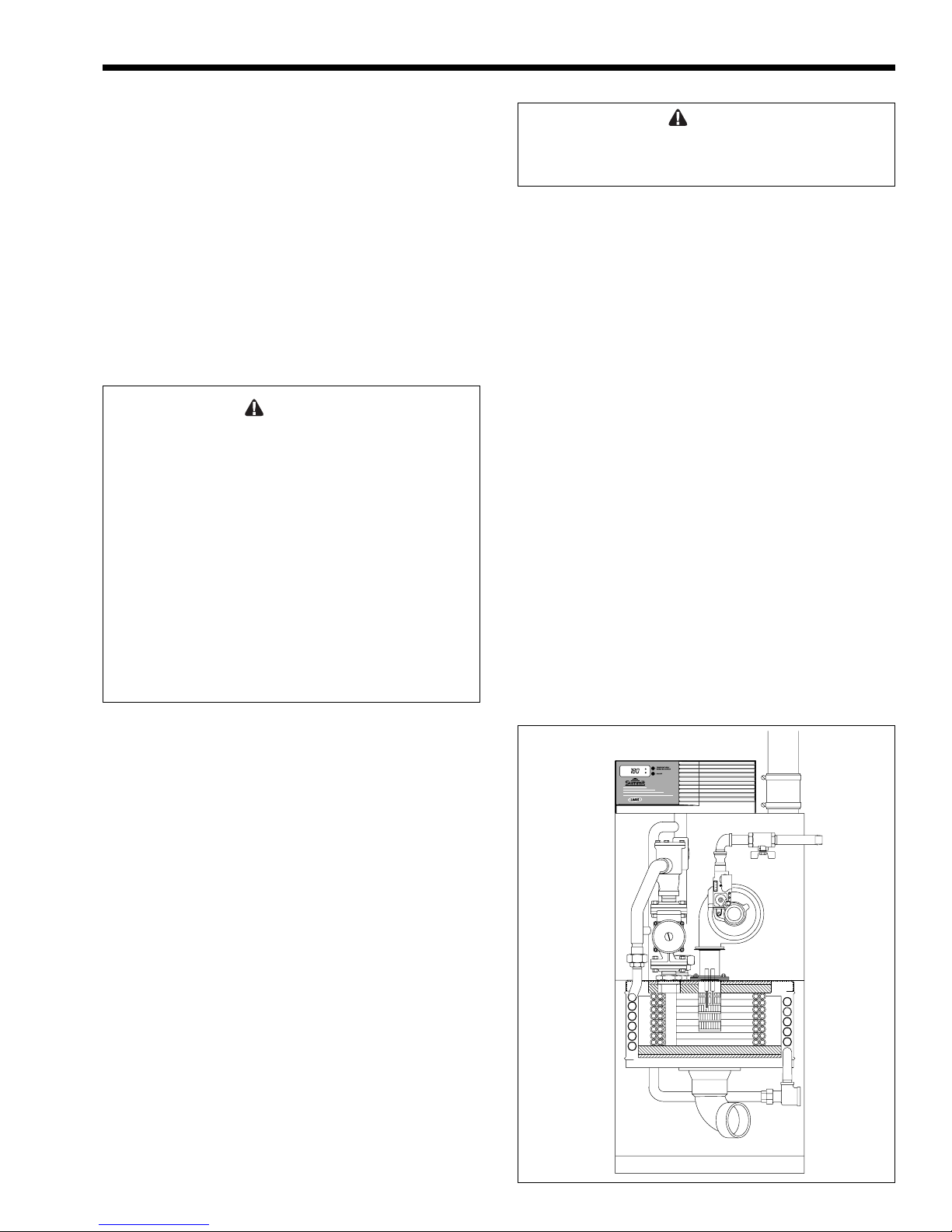
Figure 1. Assembly View of the Unit.
Page 4
Page 4
LAARS HEATING SYSTEMS
1.2 Warranty
Laars Heating Systems SUMMIT appliances are
covered by a limited warranty. The owner should fill
out the warranty registration card and return it to
Laars Heating Systems.
All warranty claims must be made to an
authorized Laars Heating Systems representative or
directly to the factory. Claims must include the serial
number and model (this information can be found on
the rating plate), installation date, and name of the
installer. Shipping costs are not included in the
warranty coverage.
Some accessory items are shipped in separate
packages. Verify receipt of all packages listed on the
packing slip. Inspect everything for damage
immediately upon delivery, and advise the carrier of
any shortages or damage. Any such claims should be
filed with the carrier. The carrier, not the shipper, is
responsible for shortages and damage to the shipment
whether visible or concealed.
1.3 Materials Installer Must Provide
1. Total combined feet allowed for intake and
exhaust vent pipe per instructions. The following
charts show acceptable materials for intake and
exhaust pipes:
The solvent cement for pipe joints must comply with
the following standards:
i. PVC pipe D2564 / ABS pipe D2235, or
CPVC pipe F493
ii. CSA listed solvent cement for the PVC,
ABS or CPVC pipe used.
2. Electrical connection to a 120VAC/15Amp service.
3. Gas connection that will provide 250 cubic feet/
hour at 4 to 13 inch w.c.
4. Condensate drainage: a floor drain is preferred,
and a condensate pump can be used if required.
Check local codes for information about proper
disposal of condensate in your area.
5. Miscellaneous copper fittings and bronze valves
will be required to complete the piping system.
Use only plastic fittings (except Nylon®) for
condensate drain lines.
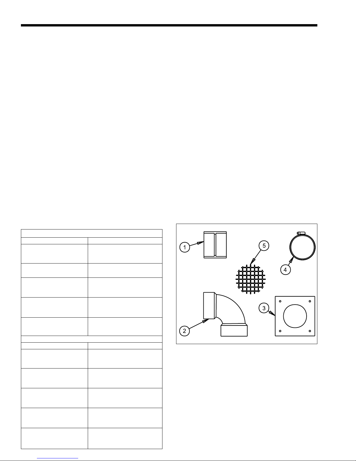
1.4 Unpacking
The SUMMIT appliance is shipped in a single
crate with the following standard components on top
of the appliance.
1. Exhaust terminal 4. Hubless couplings (2)
2. Intake terminal 5. Terminal Screens, 4” (2)
3. Backing plates (4)
Acceptable Intake Pipe Material
Model 200 Model 250
3-inch or 4-inch PVC 3-inch or 4-inch PVC
schedule 40 pipe per schedule 40 pipe per
ASTM D-1785 std. ASTM D-1785 std.
3-inch or 4-inch PVC DWV 3-inch or 4-inch PVC DWV
pipe per ASTM D-2665 std. pipe per ASTM D-2665 std.
3-inch or 4-inch ABS-DWV 3-inch or 4-inch ABS-DWV
pipe per ASTM D2661 std. pipe per ASTM D2661 std.
or ASTM F-628 std. or ASTM F-628 std.
3-inch or 4-inch CPVC 3-inch or 4-inch CPVC
schedule 40 or 80 pipe per schedule 40 or 80 pipe per
ASTM F441 std. ASTM F441 std.
3-inch or 4-inch AL29-4C 3-inch or 4-inch AL29-4C
stainless steel complying stainless steel complying
with UL Std. 1738 with UL Std. 1738
Acceptable Exhaust Vent Material
Model 200 Model 250
3-inch or 4-inch PVC 3-inch or 4-inch CPVC
schedule 40 pipe per schedule 40 or 80 pipe per
ASTM D-1785 std. ASTM F441 std.
3-inch or 4-inch PVC DWV 3-inch or 4-inch AL29-4C
pipe per ASTM D-2665 std. stainless steel complying
with UL Std. 1738
3-inch or 4-inch ABS-DWV
pipe per ASTM D2661 std.
or ASTM F-628 std.
3-inch or 4-inch CPVC
schedule 40 or 80 ipe per
ASTM F441 std.
3-inch or 4-inch AL29-4C
stainless steel complying
with UL Std. 1738
Figure 2. Contents of shipping package.
1. Remove all packing and tie-down materials.
2. Check contents of the carton against items
shown above.
1.5 Locating the SUMMIT Appliance
The appliance should be located to provide
clearances on all sides for maintenance and
inspection. It should not be located in an area where
leakage of any connections will result in damage to
the area adjacent to the appliance or to lower floors of
the structure.
Page 5
SUMMIT BOILER OR WATER HEATER
Page 5
When such a location is not available, it is
recommended that a suitable drain pan, adequately
drained, be installed under the appliance.
The appliance shall be installed so that the gas
ignition system components are protected from water
(dripping, spraying, rain, etc.) during appliance
operation or service (circulator replacement, control
replacement, etc.).
The appliance is design certified by CSAInternational (AGA / CGA) for installation on
combustible flooring; in basements; in closets, utility
rooms or alcoves. SUMMIT Boilers or Water
Heaters must never be installed on carpeting.
The location for the appliance should be chosen
with regard to the vent pipe lengths and external
plumbing, If there is potential for snow accumulation
in the local area, both vent terminals should be
installed at an appropriate level above grade.
The following dimensions and requirements
should be met when choosing the locations for the
appliance:
Clearance from
Appliance Combustible Service Access
Surface Material Clearance
U. S./Canada U. S. Canada
Left Side 1" 2.5cm 6" 15cm 24" 61cm
Right Side 1" 2.5cm 12" 30cm 24" 61cm
Top 1" 2.5cm 14" 36cm 24" 61cm
Back 1" 2.5cm 9" 23cm 24" 61cm
Front 1" 2.5cm 24" 61cm 24" 61cm
Vent 0"
Table 1. Clearances.
Example: 8' of pipe, 2 x 45° elbows and a 90°
elbow.
Equivalent Feet: 8' + (2 x 5') + (1 x 10') = 28.
If a 4" pipe size is used to permit longer vent
runs the installer must supply 4" hubless couplings (2)
and 3 x 4 bushings (2) to adapt to the appliance
fittings. The supplied vent terminals may be used with
3" diameter pipes through the outside wall. Reducing
couplings should be located inside the outside wall to
increase to the 4" pipe size. A reducing coupling and
1' of 3" pipe must be considered as 5 equivalent feet.
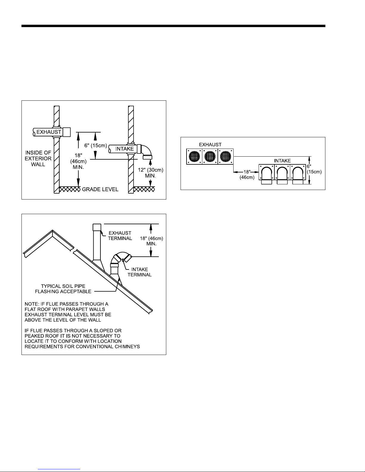
NOTE: It is required that a minimum horizontal
separation of 18" be maintained between the intake
and exhaust terminals and that both terminals be
installed on the same wall of the building. The intake
terminal must be installed at an elevation 6" below the
exhaust terminal to prevent exhaust gases from
entering the intake.
1.7 Locating Appliance for Proper
Vent Height
The vent locations you select must permit direct
pipe runs to the terminal from the appliance. Since the
SUMMIT appliance is designed to drain any water
that collects in the vent, it is important that you do not
build any traps or low points into the vent where water
could collect and restrict the vent. It is recommended
that a pitch of ¼" per foot of vent be built into the
vent system to direct any water in the vent back
toward the appliance. Note that standard DWV
elbows have a built in allowance for the required ¼"
per foot pitch.
NOTE: Roof terminations for air intake terminal
must prevent entry of rain water.
1.6 Locating Appliance for Correct Vent
Distance From Outside Wall or
Roof Termination
The forced draft combustion air blower in the
SUMMIT appliance has sufficient power to vent
properly when the following guidelines are followed.
Intake Exhaust
Maximum run: Maximum run:
3" pipe size 3" pipe size
55 equivalent feet 55 equivalent feet
4" pipe size 4" pipe size
105 equivalent feet 105 equivalent feet
Minimum run: Minimum run:
11½ equivalent feet 21 equivalent feet
Intake Terminal is Exhaust Terminal is
P/N 2400-102 P/N 2400-104
Equivalent feet is determined by adding 10
linear feet for each 90° elbow and 5 linear feet for
each 45° elbow to the actual linear feet of pipe
required to be installed.
1.8 Locating Appliance with Respect
to Ventilation
While the SUMMIT appliance requires no
indoor air for combustion, adequate airflow around
the appliance must be provided for proper cooling of
electrical components.
1.9 Locating Appliance with Respect to
Storage Tank(s)
SMW-200/250 Water Heater
For best results the SMW-200/250 water heater
should be located within 10 feet of the storage tank(s).
If the appliance must be installed with longer
piping runs, then larger diameter pipe or tubing must
be used. Calculate the necessary pipe diameter for the
installation using Table 3.
1.10Locating Appliance with Respect to
Return/Supply Header
SMB-200/250 Boiler
For the best results the SUMMIT SMB-200/250
Boiler should be located within 10 feet of the supply
and return headers.
Page 6
Page 6
LAARS HEATING SYSTEMS
If the appliance must be installed with longer
piping runs, then the larger diameter tubing must be
used. Calculate the necessary pipe diameter for the
installation using Table 3.
SECTION 2.
Venting
Figure 3. Suggested Vent Terminal Installations.
Whenever possible, locations under windows or
near doors should be avoided. Because the SUMMIT
is a condensing appliance, steaming at the flue
terminal is a normal occurrence and it should be
considered when deciding flue terminal location.
2.1.2 Intake Terminal Location
The intake pipe and terminal require a separate
4" diameter hole to install the intake fitting. The
centerline of the hole should be at least 16½" above
grade outdoors and 18" away horizontally from the
exhaust outlet. The intake should never be located
above the exhaust terminal.
Figure 5. Multiple Units Minimum Vent Terminal
Separation.
Figure 4. Alternate Vent Terminal Installations.
2.1 Locating Vent Openings On
Outside Wall
2.1.1 Exhaust Terminal Location
The exhaust pipe and terminal fitting require a
4" diameter hole through the outside wall. The
centerline of this opening must be at least 18" above
grade and at least 14" (3' in Canada) from any other
building opening such as doors, windows, etc.
Vent opening should be well away from
shrubbery or other obstructions that would block or
restrict the exhaust.
2.2 Installing Vent Piping / Terminals
The appliance is provided with intake and
exhaust terminals for use with 3" diameter plastic
pipe. If AL29-4C stainless steel venting materials that
comply with UL 1738 Standard are used, the terminals
for that system shall be used and supplied by the
installer.
The installer is responsible for obtaining the vent
pipe and fittings. The maximum combined length of
the intake and exhaust pipe and maximum number of
elbows are determined by using the guidelines in
Section 1.6.
The following steps are recommended for vent
installation of Approved plastic venting: For
installation of approved stainless steel venting
systems, follow the venting system suppliers
instructions.
1. Obtain the necessary 3" or 4" diameter plastic
piping and fittings as determined beforehand.
2. Position appliance at previously selected
location.
3. Unpack vent terminals and vent terminal backing
plates located in the box on top of appliance.
4. Cut holes in outside wall for vent terminals in
previously selected locations.
5. Mount the vent terminals backing plates.
6. Fit all of the vent pipes together without
cementing. Make sure that there are no water
traps and that any pitch is inclined back towards
the appliance.
7. Make sure that the flexible vent connections at
the appliance fit properly.
Page 7
SUMMIT BOILER OR WATER HEATER
8. Begin cementing the intake and exhaust pipes,
start at the vent terminals and work back towards
the appliance. Note: The intake terminal is the
90° elbow fitting that is designed to be
installed facing down.
9. Support both horizontal vent pipes with pipe
hangers every 5'. The weight of venting must not
be supported by appliance connectors.
10. Tighten the flexible couplings to connect the
appliance to the vent. DO NOT CEMENT
VENT PIPES TO APPLIANCE — USE
COUPLINGS PROVIDED.
SECTION 3.
Gas Connections
3.1 Gas Supply and Piping
Gas piping should be supported by suitable
hangers or floor stands, not the appliance.
Review the following instructions before
proceeding with the installation.
1. Verify that the appliance is fitted for the proper
type of gas by checking the rating plate. Laars
Heating Systems appliances are normally
equipped to operate at elevations up to 2000 feet.
However, the SUMMIT appliance will function
properly without the use of high altitude
modification at elevations up to 4500 feet (1372
m). Appliances equipped to operate at higher
altitudes have appropriate stickers or tags
attached (next to the rating plate).
2. Referring to Table 2, size supply piping to keep
flow capacity to the appliance above 250 cubic
feet per hour (CFH) per installed appliance.
3. Run gas supply line in accordance with all
applicable codes.
4. Locate and install manual shutoff valves in
accordance with state and local requirements.
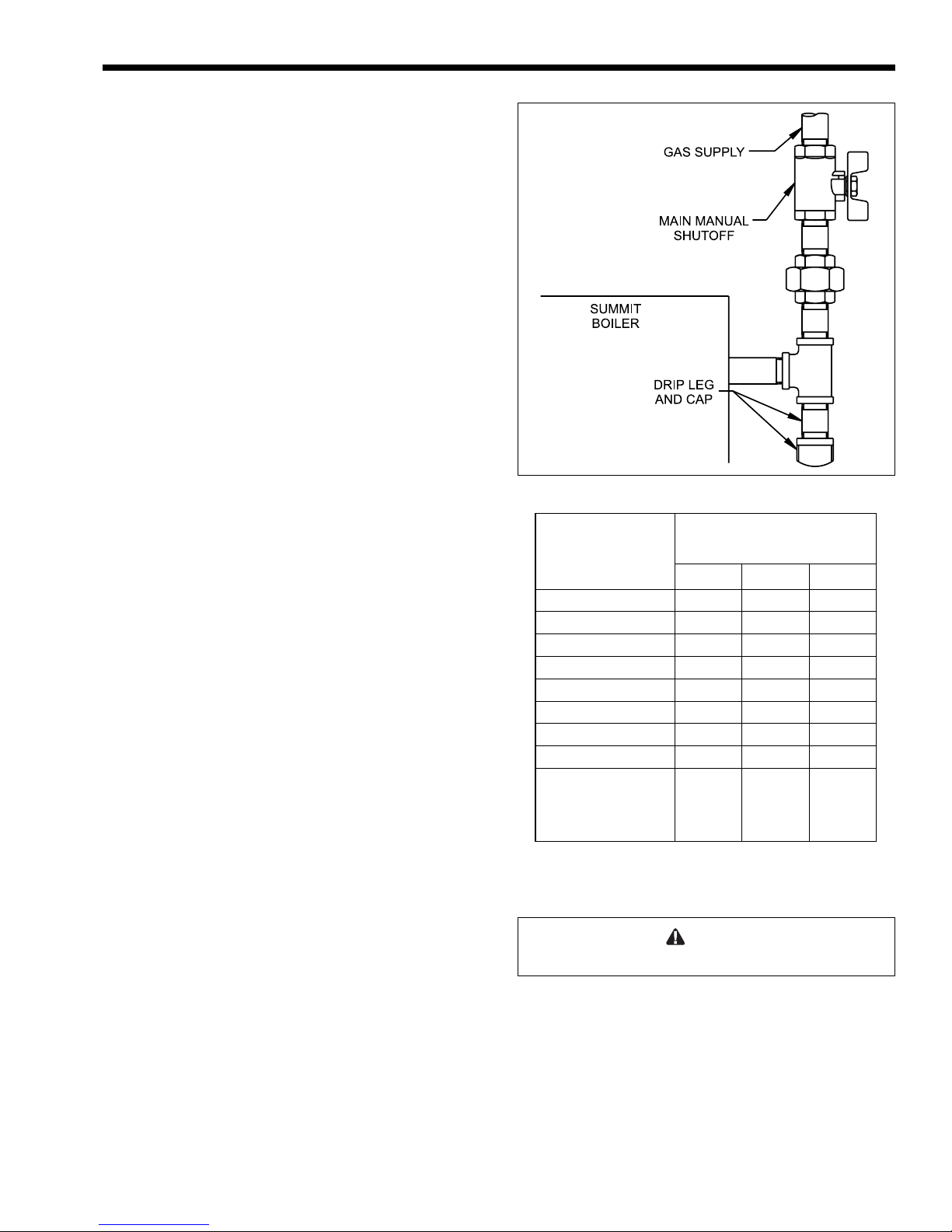
5. Install drip leg and ground joint union (Figure 6).
6. All threaded joints should be coated with piping
compound resistant to action of liquefied
petroleum gas.
7. The SUMMIT appliance and its individual
shutoff valve must be disconnected from the gas
supply piping during any pressure testing of that
system at test pressures in excess of 1/2 PSIG
(3.45kpa).
It must be isolated from the gas supply system
by closing its individual manual shutoff valve
during any pressure testing of the gas supply
piping system at test pressures equal to or less
than 1/2 PSIG (3.45kpa).
8. The SUMMIT appliance and its gas connection
must be leak tested before placing it in
operation.
Page 7
Figure 6. Gas Supply Piping.
Length
of
Pipe
10' (3m) 278 520 1,050
20' (6m) 190 350 730
30' (9m) 152 285 590
40' (12m) 130 245 500
50' (15m) 115 215 440
75' (23m) 93 175 360
100' (30m) 79 150 305
150' (46m) 64 120 250
Additional length to be
added for each tee or
bend
Table 2. Gas Supply Piping.
Capacity of Pipe in MBTU/HR (.6
Specific Gravity)
¾" 1" 1¼"
1.7'
(0.5m)
2.2'
(0.7m)
2.7'
(0.8m)
9. Purge all air from gas lines.
Caution:
Do not use open flame to check for leaks.
NOTE: The SUMMIT appliance and all other
gas appliances sharing the gas supply line must be
firing at maximum capacity to properly measure the
inlet supply pressure. The pressure can be measured at
the supply pressure port on the gas valve (Figure 20).
Low gas pressure could be an indication of an
undersized gas meter, undersized gas supply lines and/
or an obstructed gas supply line.
10. The correct burner manifold gas pressure (offset)
is pre-set at the factory, and normally requires no
further adjustment. See Section 7.2.2.1 Offset
Page 8
Page 8
l
LAARS HEATING SYSTEMS
and Throttle Adjustment for the proper method
of verification.
11. Before operating the appliance, the complete gas
supply system and all connections must be tested
for leaks using a soap solution.
SECTION 4A.
Water Connections
SMB-200/250 Boiler
4A.1 Heating System Piping:
Hot Supply Connections
NOTE: This appliance must be installed in a
closed pressure system with a minimum of 10 psi
static pressure.
Hot water piping should be supported by suitable
hangers or floor stands, NOT by the appliance. Due to
expansion and contraction of copper pipe,
consideration should be given to the type of hangers
used. Rigid hangers may transmit noise through the
system resulting from the piping sliding in the
hangers. It is recommended that padding be used
when rigid hangers are installed.
SUMMIT boilers must not be direct connected
to a heating system utilizing oxygen permeable tubing,
(see warranty). Provide a water to water heat
exchanger between systems to prevent corrosion of
internal pump, pump flanges, buffer tank (if installed)
or other components.
THE SUMMIT BOILER MUST BE
CONNECTED IN A PRIMARY/SECONDARY
TYPE SYSTEM OR WITH A FULL SIZED
BYPASS.
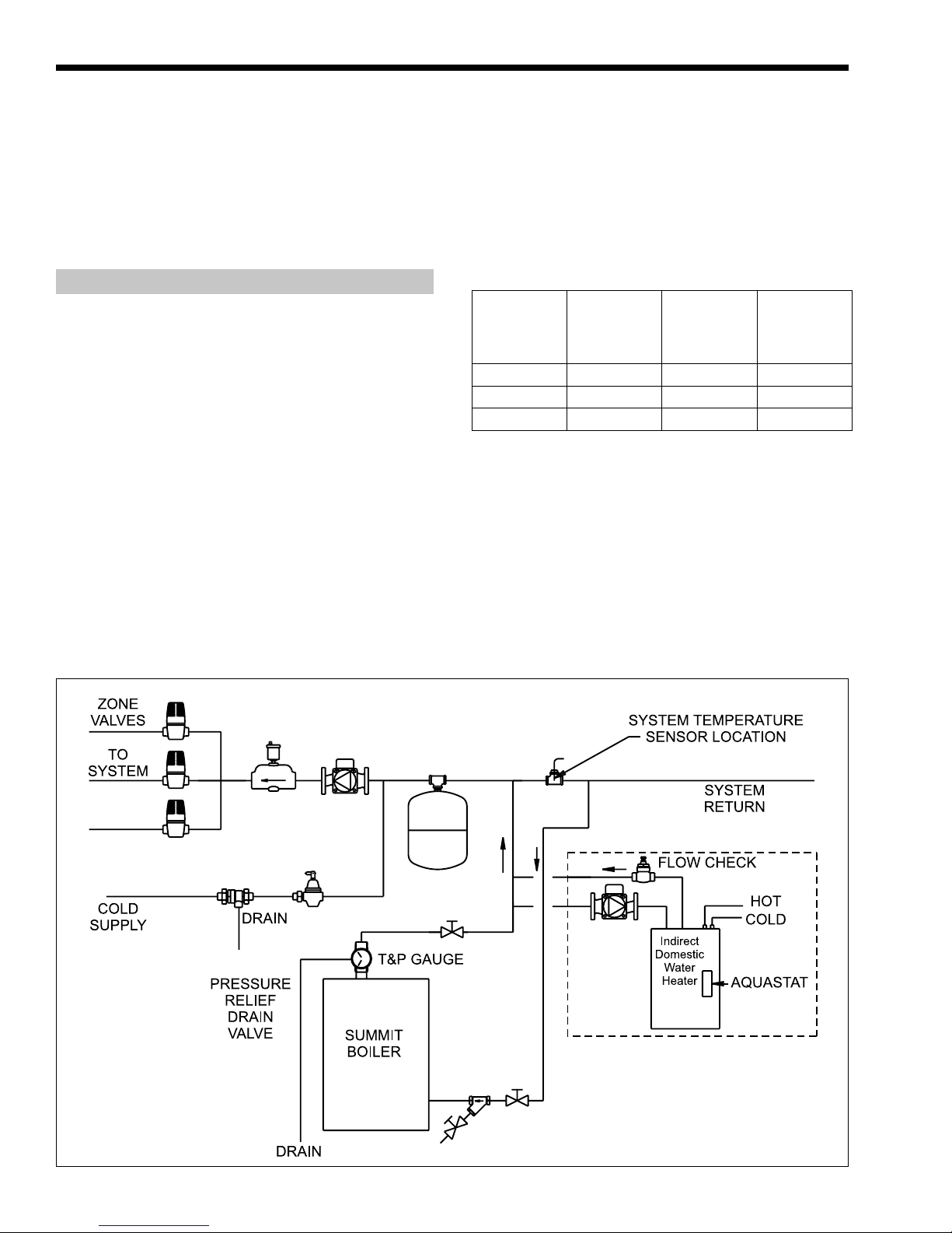
1. Connect the 1¼" supply connection on the
appliance to the system bypass. Size the
combined length of supply and return to the loop
using Table 3.
Copper tube or
pipe size
1¼" 40' (12m) 2' (0.6m) 1½' (0.5m)
1½" 120' (37m) 2' (0.6m) 1½' (0.5m)
2" 270' (82m) 2' (0.6m) 1½' (0.5m)
Table 3. Water Pipe and Tube Sizing.
Maximum
allowable tubing
length
Amount
deducted for
each additional
90° elbow
Amount
deducted for
each additiona
45° elbow
2. Pipe the discharge of the relief valve, full size, to
a drain or in a manner to prevent injury in the
event of pressure relief.
3. Install an air purger, an air vent, a diaphragm
type expansion tank, and a hydronic flow check
in the system supply loop. Minimum fill pressure
must be 12psig.
4. Install shutoff valves where required.
Figure 7. Piping for Heating and Optional Domestic Hot Water.
Page 9
SUMMIT BOILER OR WATER HEATER
Page 9
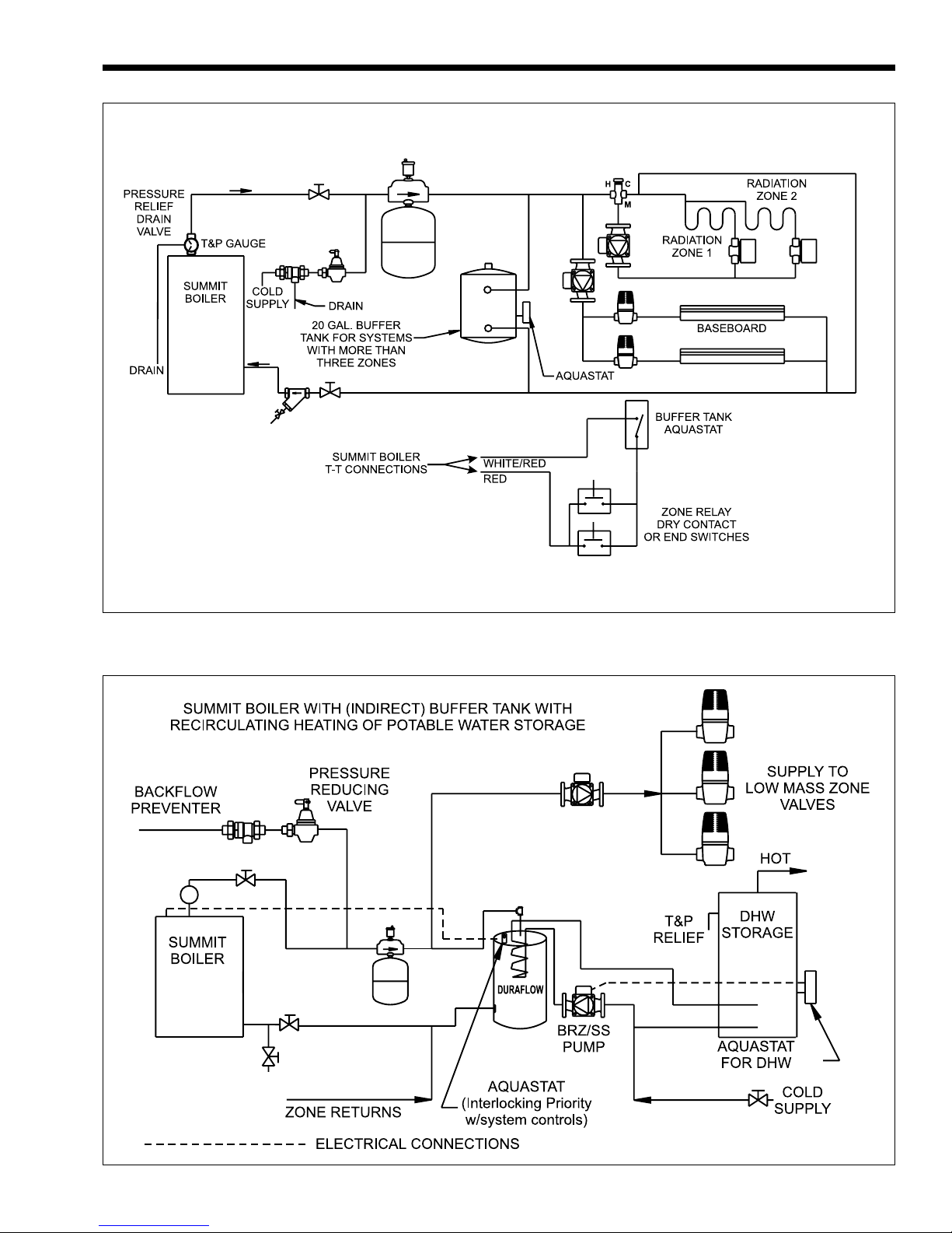
Figure 8. Radiant and Baseboard Heat with More Than Three Zones.
Figure 9. Indirect Tank as Buffer with Potable Water Storage Tank.
Page 10
Page 10
LAARS HEATING SYSTEMS
4A.2 Return Connections
1. Install a strainer between the SUMMIT boiler
and the system.
2. Connect the 1¼" return connection on the
appliance to the return side of the system
circulating loop.
3. Install a check valve (multiple appliances only),
a shutoff valve and a drain valve near the
appliance in the return line.
4. Install a properly sized circulator in the system
loop.
4A.3 Cold Water Make-Up
1. Connect the cold water supply to the inlet
connection of an automatic fill valve.
2. Install a suitable back flow preventer between
the automatic fill valve and the cold water
supply.
3. Install shut off valves where required.
NOTE: The boiler, when used in connection
with a refrigeration system, must be installed so the
chilled medium is piped in parallel with the boiler
with appropriate valves to prevent the chilled medium
from entering the boiler.
The boiler piping system of a hot water heating
boiler connected to heating coils located in air
handling appliances where they may be exposed to
refrigerated air circulation must be equipped with
flow control valves or other automatic means to
prevent gravity circulation of the boiler water during
the cooling cycle.
The boiler when installed above the radiation
level must be provided with a low water cutoff device
at the time of boiler installation.
SECTION 4B.
Water Connections
SMW-200/250 Water Heater
4B.1 Water System Piping,
Fittings and Accessories
Hot water piping should be supported by suitable
hangers or floor stands, NOT by the appliance. Due to
expansion and contraction of copper pipe,
consideration should be given to the type of hangers
used. Rigid hangers may transmit noise through the
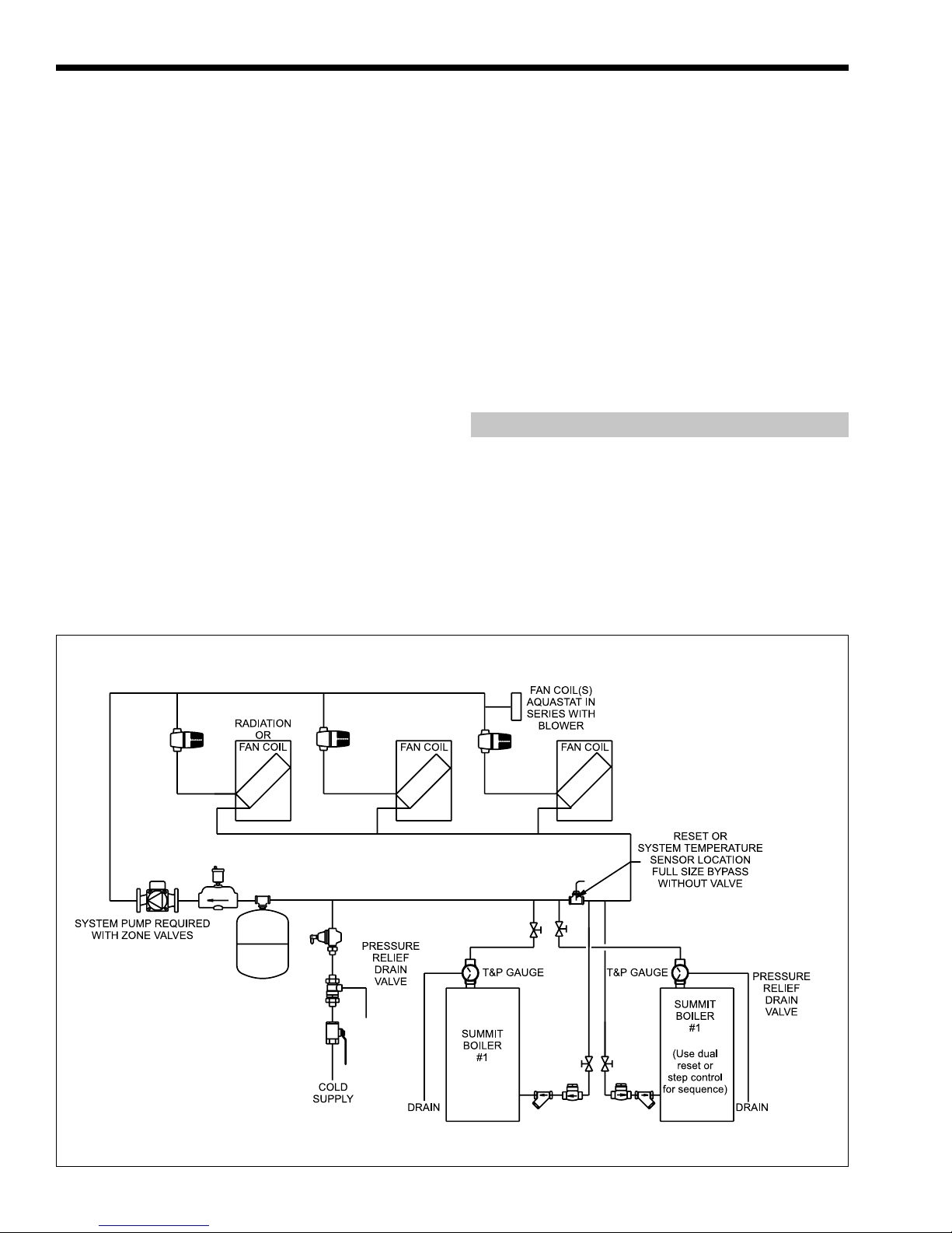
Figure 10. Piping Diagram for Modular Units and/or Hydro Air Systems.
Page 11
SUMMIT BOILER OR WATER HEATER
Page 11
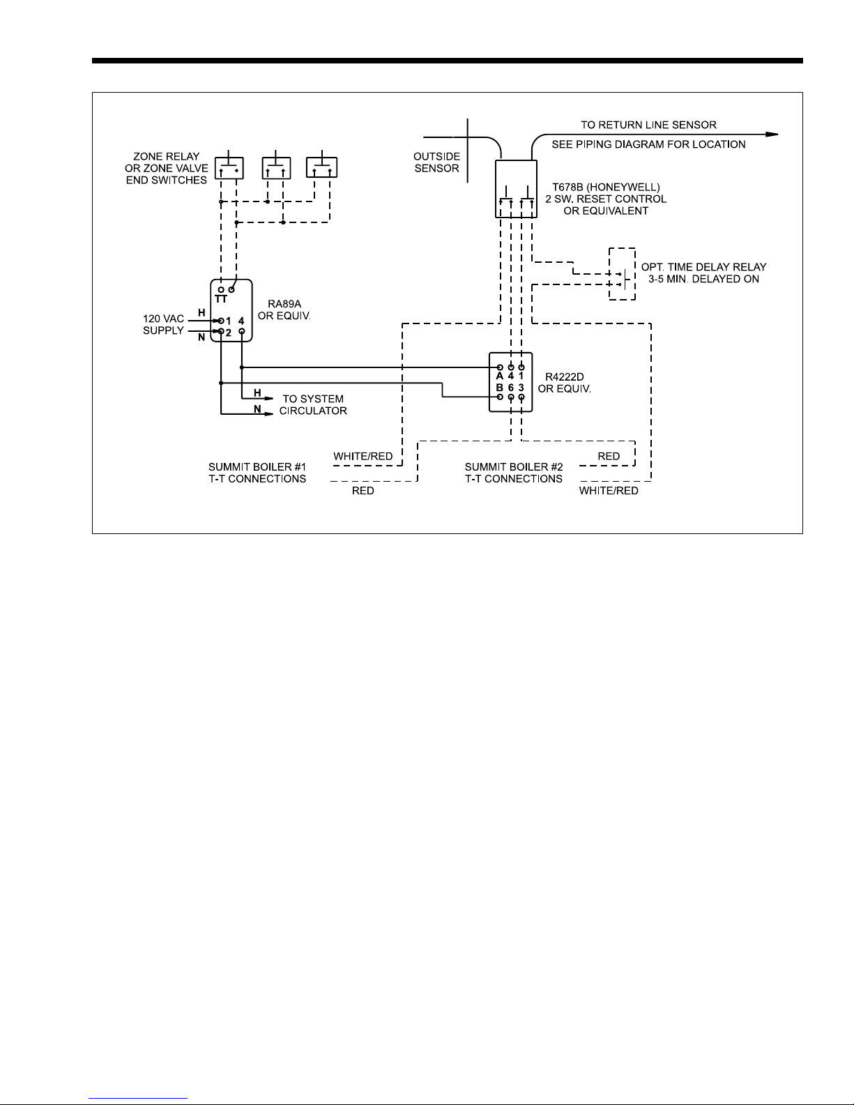
Figure 11. Wiring Diagram.
system resulting from the piping sliding in the
hangers. It is recommended that padding be used
when rigid hangers are installed.
Installing Tank & Piping
The SMW-200/250 can be used with several
different types of readily available storage tanks. A
bronze circulating pump is built into the water heater.
The pump draws water from the storage tank and
pumps the water through the heater and back into the
tank.
Position the Storage Tank(s)
At the previously selected locations, position the
storage tank(s). Use Table 3 to determine the pipe size
necessary to provide adequate flow between the
SMW-200/250 and the tank(s).
Hot Water Outlet Piping, Fittings, and
Accessories
1. Begin piping to the tank from the hot water
outlet at the top of the SMW-200/250 cabinet.
2. Pipe the outlet from the relief valve (located on
top of the appliance) such that any discharge
from the relief valve will be conducted to a
suitable place for disposal when relief occurs.
Do not reduce line size or install any valves in
this line. The line must be installed to allow
complete drainage of both the valve and the line.
3. Install a shut off valve in the piping between the
thermometer fitting and the tank.
Cold Water Supply Piping, Fittings and
Accessories
1. Install a strainer between the SMW 200/250 and
the system. For proper pipe size and distance
limitations, refer to Table 3.
2. Connect a drain valve and a shut off valve to the
SMW-200/250 cold inlet. On multiple
appliances install a check valve at each
appliance’s cold water inlet.
3. Where check valves have been installed on cold
water inlet piping, check to be sure system has
an adequately sized expansion tank to allow
thermal expansion to occur.
Page 12
Page 12
LAARS HEATING SYSTEMS
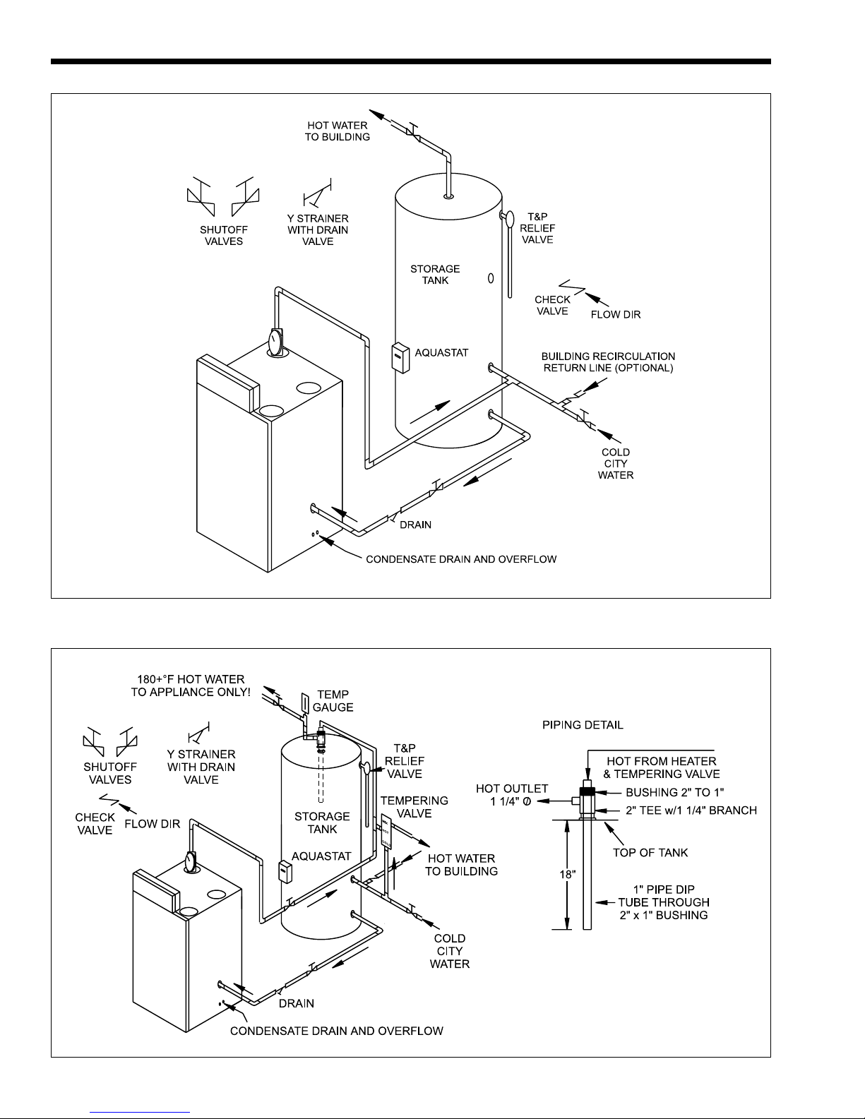
Figure 12. Single Summit Water Heater and Storage Tank.
Figure 13. Two Temperature System.
Page 13
SUMMIT BOILER OR WATER HEATER
Page 13
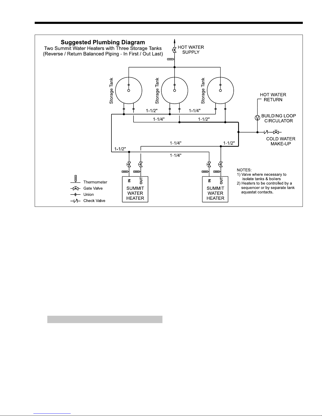
Figure 14. Multiple Summit Water Heaters and Storage Tanks.
Hot Water Supply Piping
Follow the tank manufacturer’s guidelines for
completion of the hot water system connections.
NOTE: A listed temperature and pressure
relief valve listed as complying with the Standard
for Relief Valves and Automatic Gas Shutoff
Devices for Hot Water Supply Systems, 1). ANSI
Z21.22 latest edition, or 2). CAN / CGA 1 - 4.4, of
suitable discharge capacity must be installed in the
separate storage tank system.
4B.2 Combined Water (potable)
Heating and Space Heating
SMW-200/250 Water Heater
Piping and components connected to this water
heater for the space heating application shall be
suitable for use with potable water.
Toxic chemicals, such as used for boiler
treatment, shall not be introduced into the potable
water used for space heating.
This water heater when used to supply potable
water shall not be connected to any heating system or
component(s) previously used with a non-potable
water heating appliance.
When the system requires water for heating
at temperatures higher than required for other
uses, an anti-scald mixing or tempering valve shall
be installed to temper the water for those uses in
order to reduce scald hazard potential.
SECTION 4C.
Condensate Drain Connection
NOTE: Connecting tubing must run
DOWNWARDS from the level of the fitting (see
Figure 16).
1. Connect a plastic tube between the plastic fitting
closer to the front of the appliance and a floor
drain (or optional condensate pump if a floor
drain is not accessible).
2. Connect another plastic tube between the other
plastic fitting and a drain pan.
3. The plastic tubes must not be connected
together because the second tube is a
condensate relief tube that will function to drain
condensate if the first or primary condensate
drain tube becomes blocked.
Page 14

Page 14
Figure 15. Typical Installation.
LAARS HEATING SYSTEMS
Single pole switches, including those of safety
controls and protective devices must not be wired in a
grounded line.
All electrical connections are made in the field
wiring box that is located on the left side of the
appliance.
Figure 16. Condensate Drain Tube Outlet.
SECTION 5.
Electrical Connections
WARNING
The appliance must be electrically grounded in
accordance with the requirements of the authority
having jurisdiction or, in the absence of such
requirements, with the latest edition of the National
Electrical Code, ANSI/NFPA 70, in the U.S. and with
latest edition of CSA C22.1 Canadian Electrical
Code, Part 1, in Canada. Do not rely on the gas or
water piping to ground the metal parts of the boiler.
Plastic pipe or dielectric unions may isolate the
boiler electrically. Service and maintenance
personnel, who work on or around the boiler, may
be standing on wet floors and could be electrocuted
by an ungrounded boiler.
Figure 17. Field Wiring.
NOTE: All internal electrical components have
been prewired. No attempt should be made to connect
electrical wires to any other location except the wiring
box designated above.
Wiring connections are indicated on Figure 17.
5.1 Main Power
Connect a 15 amp. fused, 120-volt supply to the
main power switch (hot leg is connected directly to
switch). Neutral leg is connected directly to the white
wire. Ground wire can be connected to the grounding
screw in the box or on the switch.
Page 15
SUMMIT BOILER OR WATER HEATER
Page 15
5.2 Temperature Control
SMB-200/250 Boiler
NOTE: Connect boiler T-T wires to isolated
contacts on zone valves, circulator relays, sequencing
controls (multiple appliance applications) or other
temperature controlled devices. DO NOT JUMPER.
If connected to a room thermostat set heat anticipator
at 0.9 amps.
5.3 Temperature Control
SMW-200/250 Water Heater
5.3.1 Water Heater Temperature Control
Connect water heater T-T wires to isolated
aquastat contacts, sequencing controls (multiple
appliance applications) or other temperature
controlled devices. DO NOT JUMPER.
5.3.2 Tank Temperature Control
The SMW-200/250 is turned on and off by a
remote tank aquastat. Locate the aquastat above the
cold water inlet fitting in the separate storage tank.
The SMW-200/250 draws water off the bottom of the
tank and pumps hot water back into the tank. When
the hot water level reaches the level of the aquastat,
the aquastat contacts will open and switch off the
SMW-200/250.
Please contact your factory representative if you
have any questions about storage tank application.
5.4 Wiring Diagram
Caution
Label all wires prior to disconnection when servicing
controls. Wiring errors can cause improper and
dangerous operation. Verify proper operation after
servicing
Page 16
Page 16
LAARS HEATING SYSTEMS
Caution
ATTENTION
SUMMIT SMB WIRING DIAGRAM
Label all wires prior to disconnection when servicing
controls. Wiring errors can cause improper and
dangerous operation.
Verify proper operation after operation servicing.
Au moment de l’entretien des commandes,
étiquetez tous les fils avant de les débrancher. Les
erreurs de câblage peuvent nuire au bon
fonctionnement et être dangereuses.
S’assurer que l’apperiel fonctionne adéquatement
une fois l’entretien terminé.
Figure 18. Wiring Diagram.
Page 17

SUMMIT BOILER OR WATER HEATER
SECTION 6. Operating Instructions
FOR YOUR SAFETY READ BEFORE OPERATING
If you do not follow these instructions exactly, a fire or explosion
may result, causing property damage, personal injury or loss of life.
Page 17
WARNING
A. This appliance does not have a pilot. It is
equipped with an ignition device which
automatically lights the burner. Do not try to
light the burner by hand.
B. BEFORE OPERATING smell all around the
appliance area for gas. Be sure to smell next
to the floor because some gas is heavier
than air and will settle on the floor.
WHAT TO DO IF YOU SMELL GAS
• Do not try to light any appliance.
• Do not touch any electric switch; do not
use any phone in your building.
• Immediately call your gas supplier from a
neighbor's phone. Follow the gas
supplier's instructions.
OPERA TING INSTRUCTIONS
1. STOP! Read the safety information above on
this label.
2. Set the thermostat to lowest setting.
3. Turn off all electric power to the appliance.
• If you cannot reach your gas supplier, call
the fire department.
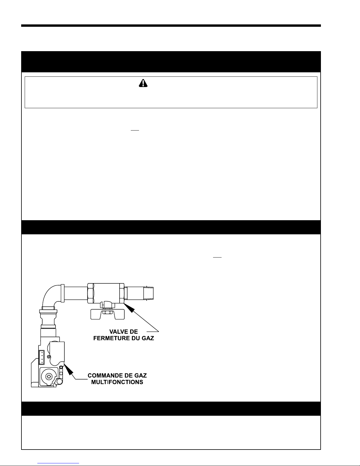
C. Turn off gas shutoff valve (located above the
combination gas control) so that the handle
is aligned across the gas pipe. If the handle
will not turn by hand, don't try to repair it, call
a qualified service technician. Force or
attempted repair may result in a fire or
explosion.
D. Do not use this appliance if any part may
have been under water. Immediately call a
qualified service technician to inspect the
appliance and to replace any part of the
control system and any gas control which
may have been under water.
4. This appliance is equipped with an ignition
device which automatically lights the burner.
Do not try to light the burner by hand.
5. Remove front cover.
6. Turn gas shutoff valve to “off”. Handle will be
aligned across gas pipe. Do not force.
7. Wait five (5) minutes to clear out any gas. If
you then smell gas, STOP! Follow “B” in the
safety information above on this label. If you
don't smell gas, go to next step.
8. Turn gas shutoff valve to “on”. Handle will be
aligned along gas pipe.
9. Turn on all electric power to appliance,
depress on/off button on control panel,
depress black button on top of control panel.
10. Replace front cover.
11. Set thermostat to desired setting.
12. If the appliance will not operate, follow the
instructions “To Turn Off Gas To Appliance”
and call your service technician or gas
supplier.
TO TURN OFF GAS T O APPLIANCE
1. Set the thermostat to lowest setting.
2. Turn off all electric power to the appliance if
service is to be performed.
3. Remove front cover.
4. Turn gas shutoff valve “off”. Handle will be
aligned across gas pipe. Do not force.
5. Replace front cover.
H2013100-
Page 18
Page 18
LAARS HEATING SYSTEMS
Section 6. Notice d’utilisation
PAR MESURE DE PRUDENCE, LISEZ CE QUI SUIT AVANT DE FAIRE
FONCTIONNER L’APPAREIL
AVERTISSEMENT
Si vous ne suivez pas ces instructions à la lettre, un incendie ou une explosion pourrait se
produire et causer des dommages matériels, des blessures personnelles ou même la mort.
A. Cet appareil n’est pas doté d’une veilleuse. Il est
équipé d’un dispositif d’allumage qui allume
automatiquement le brûleur. Ne tentez pas d’allumer
le brûleur manuellement.
B. AVANT D’UTILISER, vérifiez s’il n’y a pas d’odeur de
gaz autour de l’appareil. Vérifiez s’il n’y a pas
d’odeur de gaz près du plancher, car le gaz est plus
lourd que l’air et peut se déposer sur le plancher.
QUE FAIRE EN CAS D’ODEUR DE GAZ
• N’essayez pas d’allumer n’importe quelque
appareil que ce soit.
• Ne touchez pas à un commutateur électrique.
N’utilisez pas le téléphone de votre résidence.
• Appelez immédiatement votre fournisseur de gaz
en utilisant le téléphone de votre voisin. Suivez
les instructions de votre fournisseur de gaz.
NOTICE D’UTILISATION
1. ARRÊTEZ ! Lisez l’information de sécurité ci-dessus,
sur cette étiquette.
2. Réglez le thermostat au réglage le plus bas.
3. Coupez l’alimentation électrique à l’appareil.
• Si vous ne pouvez joindre votre fournisseur de
gaz, appelez le service des incendies.
C. Fermez la soupape d’arrêt de gaz (située au-dessus
de la commande de gaz multifonctions) de sorte que
la poignée soit perpendiculaire au tuyau de gaz. Si
vous ne pouvez tourner la poignée à la main,
n’essayez pas de la réparer. Communiquez avec un
technicien de service qualifié. Le fait de forcer ou de
tenter de réparer la poignée pourrait causer un
incendie ou une explosion.
D. N’utilisez pas cet appareil si l’une des pièces a été
submergée sous l’eau. Communiquez
immédiatement avec un technicien de service
qualifié afin qu’il inspecte l’appareil et remplace toute
pièce du système de commande et toute commande
de gaz qui aurait été submergée sous l’eau.
4. Cet appareil est doté d’un dispositif d’allumage qui
allumera automatiquement le brûleur.
Ne tentez pas d’allumer le brûleur manuellement.
5. Retirez le couvercle avant.
6. Mettez la soupape d’arrêt de gaz à «off». La poignée
se trouvera perpendiculaire au tuyau de gaz.
N’employez pas de force.
7. Attendez cinq (5) minutes afin que le gaz se dissipe.
Si vous croyez sentir une odeur de gaz, ARRÊTEZ !
Reportez-vous aux instructions du paragraphe B cidessous, sur cette étiquette. S’il n’y a pas d’odeur de
gaz, passez à la prochaine étape.
8. Mettez la soupape d’arrêt de gaz à «on». La poignée
sera parallèle au tuyau de gaz.
9. Rétablissez l’alimentation électrique à l’appareil,
appuyez sur le bouton «on/off» qui se trouve sur le
panneau de commande, appuyez sur le bouton noir
qui se trouve sur le panneau de commande.
10. Replacez le couvercle avant.
11. Réglez le thermostat à la température désirée.
12. Si l’appareil ne fonctionne pas, suivez les directives
relatives à la fermeture de l’alimentation en gaz et
communiquez avec votre technicien de service ou le
fournisseur de gaz.
FERMETURE DE L’ALIMENTATION EN GAZ À L’APPAREIL
1. Réglez le thermostat au réglage le plus bas.
2. Coupez toute alimentation électrique à l’appareil si
celui-ci doit faire l’objet d’un entretien.
3. Retirez le couvercle avant.
4. Mettez la soupape d’arrêt de gaz à «off». La poignée
se trouvera perpendiculaire au tuyau de gaz.
N’employez pas de force.
5. Replacez le couvercle avant.
H2013100-
Page 19

SUMMIT BOILER OR WATER HEATER
Page 19
6.1 Anti Freeze
SMB-200/250 Boilers
Proper precautions for freeze protection are
recommended for boiler installations in areas where
the danger of freezing exists.
6.1.1 Summit Boiler Low Temperature
Feature
Summit boilers are equipped with a Low
Temperature control feature that recognizes when the
water temperature at the outlet of the boiler has fallen
below 39°F (4°C). If this condition is recognized, the
Summit pump will run for 5 minutes, or until the
boiler outlet temperature reaches 45°F (7°C). If the
boiler outlet temperature remains below 45°F (7°C)
for 5 minutes, the appliance will start its ignition
sequence, in hopes of firing the boiler and heating the
water. The display will show [ICE] during this time.
This feature is intended to assist in protecting the
boiler from freezing conditions, and does not help to
protect any other part of the heating system. This
feature will only help when there is power to the
boiler and when the internal water flow components in
the Summit are working properly. This feature will
not be able to prevent freezing if the low temperature
water condition persists. See section 6.1.2 for
information concerning further freeze protection for
the Summit.
6.1.2 Anti-Freeze Boiler Additives
Power outage, interruption of gas supply, failure
of system components, activation of safety devices,
etc., may prevent a boiler from firing. Any time a
boiler is subjected to freezing conditions, and the
boiler is not able to fire, and/or the water is not
able to circulate, there is a risk of freezing in the
boiler or in the pipes in the system. When water
freezes, it expands. This can result in bursting of
pipes in the system, or damage to the boiler, which
could result in leaking or flooding conditions.
Do not use automotive anti-freeze. Maintaining
a mixture of minimum 65% water and maximum 35%
properly inhibited HVAC glycol, which contains an
anti-foamant, is the preferred method of freeze
protection for Summit boilers. Percentage of glycol
used in the Summit boiler must not exceed 35%.
Typically, this mixture will serve as freeze protection
for temperatures down to approximately 0°F (-18°C),
and will serve as burst protection for temperatures
down to approximately –35°F (-30°C).
IMPORTANT NOTES: Different glycol
products may provide varying degrees of protection.
Glycol products must be maintained properly in a
heating system, or they may become ineffective.
Consult the glycol specifications, or the glycol
manufacturer, for information about specific products,
maintenance of solutions, and set up according to your
particular conditions.
6.2 Anti-Freeze SMW-200/250 Water
Heater
Summit water heaters are equipped with a Low
Temperature control feature that recognizes when the
water temperature at the outlet of the heater has fallen
below 39°F (4°C). If this condition is recognized, the
Summit pump will run for 5 minutes, or until the
heater outlet temperature reaches 45°F (7°C). If the
heater outlet temperature remains below 45°F (7°C)
for 5 minutes, the appliance will start its ignition
sequence, in hopes of firing the heater and heating the
water. The display will show [ICE] during this time.
This feature is intended to assist in protecting the
heater from freezing conditions, and does not help to
protect any other part of the water heater system. This
feature will only help when there is power to the
heater and when the internal water flow components
in the Summit are working properly. This feature will
not be able to prevent freezing if the low temperature
water condition persists.
Power outage, interruption of gas supply, failure
of system components, activation of safety devices,
etc., may prevent a heater from firing. Any time a
heater is subjected to freezing conditions, and the
heater is not able to fire, and/or the water is not
able to circulate, there is a risk of freezing in the
heater or in the pipes in the system. When water
freezes, it expands. This can result in bursting of
pipes in the system, or damage to the heater, which
could result in leaking or flooding conditions.
Anti-freeze additives, such as glycol, must not be
used in a direct potable water heating system, such as
the Summit SMW.
6.3 Filling the System
1. Open all supply and return valves.
2. Fill system to minimum operating pressure 12
psig.
3. Bleed air from the coin vent on the top of the
mixing valve.
4. Purge all lines by opening vents.
5. Turn off gas shutoff valve located above gas
valve.
6. Switch on 120 volt power, the display will
initially display [
displaying [OFF].
7. If the flow (appliance discharge) temperature
sensor is detecting a temperature below 39°F
(4°C) it will display [ICE]. The appliance will
then be in its Low Temperature Feature. The
Summit will call for the pump to run for 5
minutes, or until the discharge temperature
reaches 45°F (7°C). If the water temperature
remains below 45°F (7°C) for 5 minutes, the
Summit will attempt an ignition, in hopes of
warming the water. After three attempts to
---
] for five seconds before
Page 20
Page 20
LAARS HEATING SYSTEMS
ignite, the burner control will lock out and
display [LO] (see Figure 19).
8. If the display remains at [OFF], press the on/off
button (located at the right of the LED display)
and the reset button on top of the control panel.
The pump and the blower will start, the display
will then successively indicate [Bft] (appliance
discharge temperature) for 1 second and the
actual temperature in degrees F for 3 seconds.
The appliance will attempt to ignite three times
after which it will lock out and display [LO].
The fan will stop and the pump will run on for a
short period and then it will stop. Ensure that the
system is fully discharged of all air and the water
charge pressure is correct.
9. Switch off the main electrical supply.
10. System is now ready for operation.
Do not use this appliance if any part has been under
water. Immediately call a qualified service technician
to inspect the appliance and to replace any part of
the control system and any gas control that may
have been under water.
WARNING
6.4 Operating the Burner and Set Up
(Refer to page 16)
The Summit condensing modulating appliance
utilizes an advanced, state-of-the-art design. Proper
setup is essential for safe and reliable operation.
Problems such as failure to start, rough ignition,
strong exhaust odors, etc. can be due to improper
setup. Damage to the boiler resulting from improper
setup is not covered by the limited warranty.
REQUIRED TOOLS:
CO2 or O
Minihelic
reading –0.01 inches w.c., and a T-40 Torx
Screwdriver.
1. Using this manual, make sure the installation is
complete and fully in compliance with the
instructions.
2. Determine that the appliance and system are
filled with water and all air has been bled from
both. Open all valves.
3. Observe all warnings on the Operating
Instructions label and turn on gas and electrical
power to appliance.
4. Switch on the appliance power switch located on
the left side of the control box.
5. If the appliance display indicates “bFt” and then
temperature, go to step 6. If the display indicates
“OFF”, depress the ON/OFF button. If the
display indicates “LO” press the reset button.
Analyzer, Slope Gage, Magnehelic® or
2
®
Differential Pressure Gage capable of
6. The Summit will enter the start sequence. The
blower and pump come on for pre-purge, then
the ignitor warmup sequence starts and finally,
the gas valve opens. If ignition doesn’t occur and
display indicates “LO”, check that there is
proper gas supply. Wait 5 minutes and depress
the reset button to re-start ignition. If ignition
still does not occur, and the display indicates
“LO”, remove the front cover and turn the
venturi throttle adjustment screw counterclockwise four full turns. Wait 5 minutes and
depress the reset button to restart the ignition
sequence.
7. After the appliance starts, remove the front cover
(if necessary). Remove the 1/8" NPT plastic plug
from the flue pipe and insert your CO
analyzer probe. Obtain the CO
2
or O
or O
2
reading
2
2
and compare it to the value in Table 4. Adjust
the reading to match that value. To decrease CO
2
or increase O2 turn the venturi throttle adjusting
screw clockwise (see Figure 20 for identification
of adjustment points.) To increase CO
decrease O
, turn counter-clockwise. NOTE: if
2
2
or
adjusting procedure does not respond as
described, turn the adjusting screw clockwise
until the CO
values start to decrease (they will
2
initially increase to 11.9% for natural gas or
13.8% for LP gas, and then respond as described
above.) (If adjusting with an O
analyzer
2
disregard this note and turn screw in either
direction until the correct setting is obtained.)
After the CO
or O2 has been adjusted to the
2
proper value, proceed to step 8.
8. Loosen the screw in the offset pressure port one
turn and push the gage hose over the port and
screw. Adjust offset pressure, if necessary, by
removing the cover over the offset pressure
adjusting screw and turning the screw until the
proper value is obtained. Obtain another CO
O
reading. If necessary, again adjust the CO2 or
2
O
to the proper value as in step 7. If the offset
2
2
or
pressure has changed, adjust it to the proper
®
value. When both the CO
or O2 reading and the
2
offset pressure reading are correct, remove hose
and tighten screw in port. Replace cover over
offset adjustment, remove sample line from flue
pipe and replace the 1/8" NPT plastic plug.
Replace the appliance front cover and check
operation.
9. After placing the appliance in operation, the
Burner Safety Shutoff Device must be tested.
To test:
(a) Close gas shutoff valve with burner
operating.
(b) The flame indicator light will go out and
blower will continue to run for the post
purge cycle. Three additional attempts to
light will follow including pre-purge,
ignitor on, valve/flame on and post purge.
Page 21
SUMMIT BOILER OR WATER HEATER
Page 21
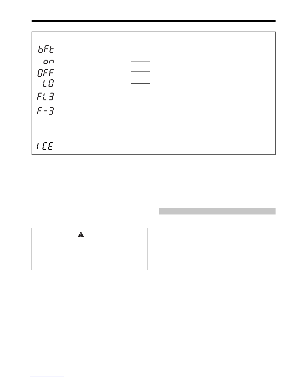
Message
Identifies
Appliance Discharge Temp
(Supply)
On
Off
Lock Out
Third Failure (Failure Level)
Fault Code (Three) There are 7
different Fault Codes defined.
Low Water Temperature
Figure 19. Typical Display Identification Codes.
Ignition will not occur as the gas is off. The
display will eventually show [LO]
approximately 10 seconds after the gas
valve has closed on the third ignition
attempt.
(c) Open gas shutoff valve. Press reset button
on the top of the control panel. The ignition
sequence will start again and the burner
will start. The appliance will return to its
previous mode of operation.
Caution
Should any odor of gas be detected, or if the gas
burner does not appear to be functioning in a normal
manner, close main shutoff valve, do not shut off
switch, and contact your heating contractor, gas
company, or factory representative.
10. Check burner input. Appliance should be in
operation for 5 minutes before checking input
and all other appliances served by the gas meter
should be shut off. With the burner operating at
full input, determine the time required for the
gas meter to deliver one cubic foot (CF) of gas.
The time should be between 14.1 and 14.7
seconds for appliances operating on natural gas.
For appliances operating on propane, the time
should be between 35.3 and 36.7 seconds. Most
propane installations do not have a gas meter. If
no meter exists and the CO
or O2 is within
2
specification, the input will be correct. If
adjustments are required, see Section 7.2.2.1 –
Offset and Throttle Adjustment.
To read or change mode
During operation display will default to supply
temperature.
Appliance in standby mode: will operate on call for
domestic water or heat zone demand.
Appliance switched OFF. Press ON/OFF button for “ON”.
After three trials for ignition, will stand in lockout. Press
reset on top of panel to retry.
Fault codes in memory apply to only to past failure
conditions and are not indicative of current failure
condition. Fault code pertaining to current failure
condition will be displayed on readout prior to entering
memory. To monitor, press and hold temperature button
for five seconds. Display will indicate first of eight fault
memories (FL1). Then display one of seven fault
conditions that occurred previously. Display will sequence
through the eight memories (see Section 8.3 for fault
codes).
Sensor has detected return temperature below 39°F (4°C).
6.5 Mode and On/Off Buttons Operation
The on/off button is used to switch the appliance
from standby [ON] to standby [OFF] and vice versa. It
is NOT an isolation switch. The mode button accesses
all other functions as shown in Figure 19.
6.6 Common Vent Test
SMB-200/250 Boilers
When an existing boiler is removed from a
common venting system, the common venting system
is likely to be too large for proper venting of the
appliances remaining connected to it.
At the time of removal of an existing boiler, the
following steps shall be followed with each appliance
remaining connected to the common venting system
placed in operation, while the other appliances
remaining connected to the common venting system
are not in operation.
1. Seal any unused openings in the common
venting system.
2. Visually inspect the venting system for proper
size and horizontal pitch and determine there is
no blockage or restriction, leakage, corrosion
and other deficiencies which could cause an
unsafe condition.
3. Insofar as it is practical, close all building doors
and windows and all doors between the space in
which the appliances remaining connected to the
common venting system are located and other
spaces of the building. Turn on clothes dryers
and any appliance not connected to the common
venting system. Turn on any exhaust fans, such
as range hoods and bathroom exhausts, so they
will operate at maximum speed. Do not operate a
Page 22

Page 22
LAARS HEATING SYSTEMS
summer exhaust fan. Close fireplace dampers.
4. Place in operation the appliance being inspected.
Follow the lighting instructions. Adjust
thermostat so appliance will operate
continuously.
5. Test for spillage at the draft hood relief opening
after 5 minutes of main burner operation. Use
the flame of a match or candle, or smoke from a
cigarette, cigar or pipe.
6. After it has been determined that each appliance
remaining connected to the common venting
system properly vents when tested as outlined
above, return doors, windows, exhaust fans,
fireplace dampers and any other gas burning
appliance to their previous conditions of use.
7. Any improper operation of the common venting
system should be corrected so that the
installation conforms to the National Fuel Gas
Code, ANSI Z223.1. When resizing any portion
of the common venting system, it should be
resized to approach the minimum size as
determined using the appropriate tables in
Appendix G in the National Fuel Gas Code,
ANSI Z223.1.
5. Faire fonctionner le brûleur principal pendant 5
min ensuite déterminer si le coupe-tirage
déborde à l’ouverture de décharge. Utiliser la
flamme d’une allumette ou d’une chandelle ou la
afumée d’une cigarette, d’une cigare ou d’une
pipe.
6. Une fois qu’il a été déterminé, selon la méthode
indiquée ci-dessus, que chaque appareil raccordé
au systéme d’évacuation est mis à l’air libre de
façon adéquate. Remettre les portes et les
fenêres, les ventilateurs, les registres de
cheminées et les appareils au gaz à leur position
originale.
7. Tout mauvais fonctionnement du systéme
d’évacuation commun devrait êvacuation
commun devrait être corrigé de façon que
l’installation soit conforme au National Fuel
Gas Code, ANSI Z223.1/NFPA 54 et (ou) aux
codes d’installation CAN/CGA-B149. Si la
grosseur d’une section du systéme devrait être
modifié ppour respecter les valeurs minimales
des tableaux pertinents de l’appendice F du
National Fuel Gas Code, ANSI Z223.1/NFPA 54
et (ou) des codes d’installation CAN/CGA-B149.
6A. Common Vent Test
Au moment du retrait d’une chaudière existante,
les mesures suivantes doivent être prises pour chaque
appareil toujours raccordé au système d’evacuation
commun et qui fonctionne alors que d’autres appareils
toujours raccordés au système d’évacuation ne
fonctionnent pas:
1. Sceller toutes les ouvertures non utilisées du
système d’évacuation.
2. Inspecter de façon visuelle le système
d’évacuation pour déterminer la grosseur et
l’inclinaison horiztonale qui conviennent et
s’assurer que le système est exempt
d’obstruction, d’étranglement, de fuite, de
corrosion et autres défaillances qui pourraient
présenter des risques.
3. Dans la mesure du possible, fermer toutes les
portes et les fenêtres du bâtiment et toutes les
portes entre l’espace, où les appareils tojours
raccordés et les autres espaces du bâtiment.
Mettre en marche les sécheuses, tous les
appareils non raccordés au système d’évacuation
commun et tous les ventilateurs d’extraction
comme les hottes de cuisinère et les ventilateurs
des salles de bain. S’assurer que ces ventilateurs
fonctionnent à la vitesse maximale, Ne pas faire
fonctionner les ventilateurs d’été. Fermer les
registres des cheminées.
4. Mettre l’appareil inspecté en marche. Suivre les
instructions d’allumage. Régler le thermostat de
façon continue.
SECTION 7.
Maintenance
7.1 System Maintenance
1. Lubricate the system water-circulating pump, if
required, per the instructions on the pump. The
internal pump in the SUMMIT appliance is
water lubricated and requires no lubrication.
2. If a strainer is employed in a pressure reducing
valve or the piping, clean it every six months.
3. Inspect the venting system for obstruction or
leakage at least once a year.
4. Keep the appliance area clear and free from
combustible materials, gasoline, and other
flammable vapors and liquids.
5. If the appliance is not going to be used for
extended periods in locations where freezing
normally occurs, it should be isolated from the
system and completely drained of all water. To
accomplish this, remove the front cover, attach a
hose to the appliance drain valve and open the
valve. Also, open the air vent on top of the
mixing valve to permit the entrance of air to
displace the appliance water being drained.
The gas and electric controls on the appliance
are engineered for long life and dependable operation,
but the safety of the equipment depends on their
proper functioning. It is strongly recommended that a
qualified service technician inspect the basic items
listed below every year.
Page 23
SUMMIT BOILER OR WATER HEATER
a. Ignition/Water temperature control
b. Automatic gas valve
c. Internal Pump
6. Low water cutoffs, if installed, should be
inspected and flushed periodically.
Page 23
Do not use this appliance if any part has been
under water. Immediately call a qualified service
technician to inspect the appliance and to
replace any part of the control system and any
gas control that may have been under water.
WARNING
7.2 Appliance Maintenance and
Component Description
7.2.1 Appliance Pump
The appliance pump operates whenever there is
a call for heat / hot water.
It is a wetted-rotor type pump and should always
be filled with water when it is operating so that it will
cool properly.
If a pump change is required for any reason,
valve off the boiler and drain approximately 1 or 2
gallons (approx. 4-8L) of water from it. Turn off the
main disconnect switch and unplug the pump wires,
remove the pump motor. The pump housing need not
be removed. The replacement pump motor should be
installed in the reverse order. After filling the system
be sure the combustion chamber coil is vented through
the air vent located on top of the mixing valve.
7.2.2 Gas Valve
The gas valve is a solenoid operated, negative
pressure regulated ratio valve. If necessary it may be
adjusted as described in Section 7.2.2.1 below. It is
designed to operate with supply pressures of 4-13
inches w.c. (1.0 to 3.2 kPa). To remove the gas valve,
shut off 120-volt power and the gas shutoff valve.
Remove the four screws from the upper flange, the
three venturi mounting screws and remove the
retaining screw and gas valve rectifier. The valve may
now be removed. After the valve has been removed,
replace with a new valve in the reverse order. Turn on
gas shutoff valve and 120 volt power and check
appliance operation and gas tightness of gas valve
connections. Set the gas valve offset pressure.
7.2.2.1 Offset and Throttle Adjustment
If poor combustion is suspected because of a
strong exhaust smell, pulsation in the exhaust, or
nuisance flame failure lockouts, the gas valve throttle
and offset pressure and exhaust CO
checked and adjusted, if required. A Magnehelic®
pressure gauge (with 0.02-in. W.C. divisions) and a
CO
or O2 tester are required for this adjustment.
2
or O2 should be
2
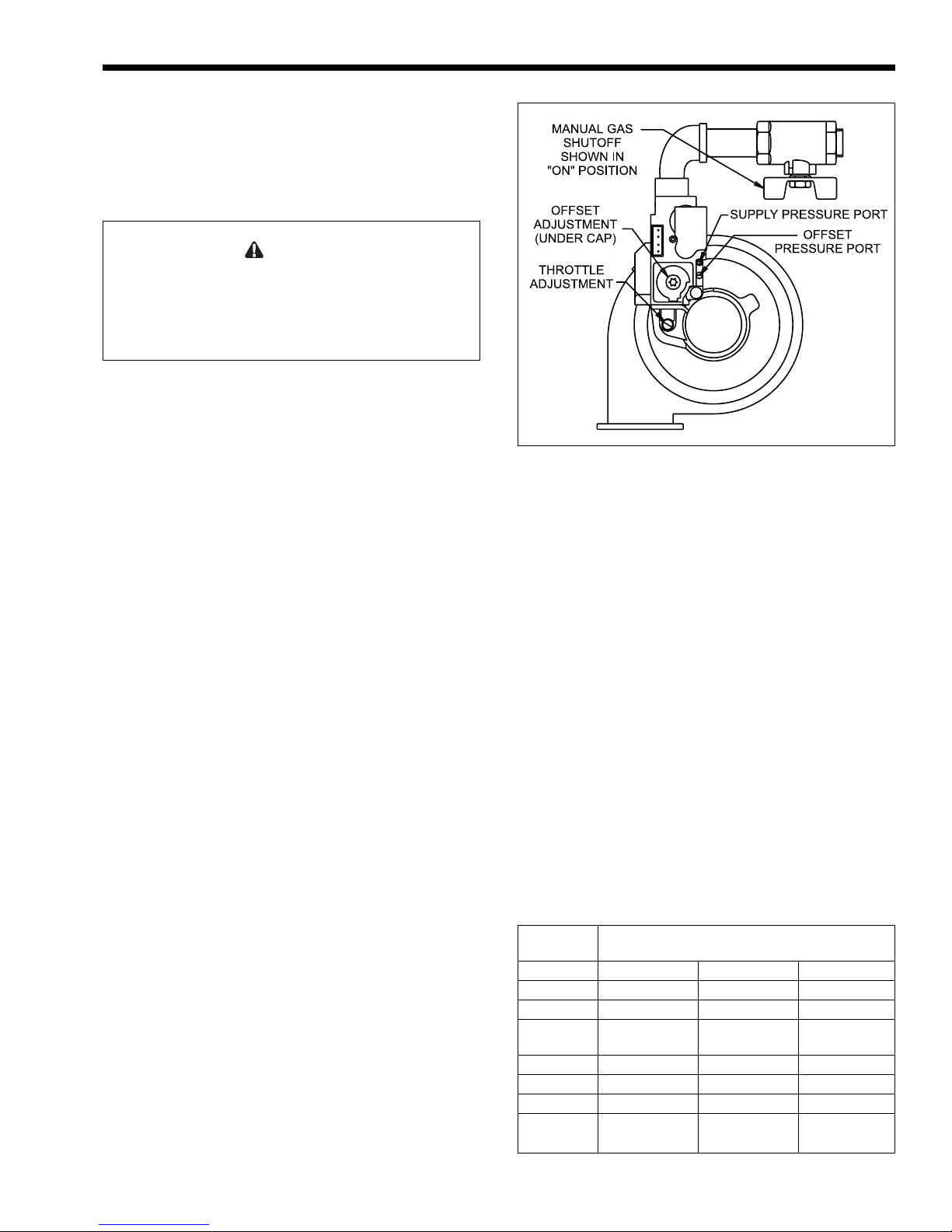
Figure 20. Gas Valve and Venturi Adjustment Points.
or O2 sampling may be taken at the exhaust
CO
2
terminal or at the sample port on the 3" exhaust
located inside the front cover. If the CO
or O2 is out
2
of specification, the throttle adjustment should be
checked. The most effective method of checking is by
clocking the gas meter. Improper throttle adjustment
resulting in low input and low CO
(or high O2) can be
2
corrected by turning the throttle adjustment screw
counter clockwise. Turn clockwise to decrease input
and CO
(or increase O2). See Figure 20 for the
2
location of the offset pressure port and the offset and
throttle pressure adjustment. After the throttle
adjustment has been completed and the input and CO
or O2 are properly set, the offset pressure should be set
to the values shown in Table 4.
When adjusting the offset pressure, the CO
reduce slightly or the O
will increase slightly as the
2
will
2
offset pressure is adjusted more negative. Adjust
throttle adjustment again to obtain desired CO
or O2.
2
Offset pressure will not change when this adjustment
is done.
Equivalent Feet of Vent &
Combustion Air Pipe Combined
Natural Gas Up to 20 ft. (6m) 21-89 ft. (6-27m) 90-110 ft. (27-34m)
CO2 Percent 9.1 +_ 1 9.0 +_ 1 8.9 +_ 1
O2 Percent 5.0 +_ 0.6 5.1 +_ 0.6 5.2 +_ 0.6
Offset Pressure -0.016+_0.004 in. WC -0.020+_0.004 in. WC -0.024+_0.004 in. WC
-0.04+_0.04 mbar -0.05+_0.04 mbar -0.06+_0.04 mbar
Propane Gas Up to 20 ft. (6m) 21-89 ft. (6-27m) 90-110 ft. (27-34m)
CO2 Percent 10.2 +_ 1 10.1 +_ 1 10.0 +_ 1
O2 Percent 5.5 +_ 0.7 5.7 +_ 0.7 5.8 +_ 0.7
Offset Pressure -0.020+_0.004 in. WC -0.024+_0.004 in. WC -0.028+_0.004 in. WC
-0.05+_0.04 mbar -0.06+_0.04 mbar -0.07+_0.04 mbar
Table 4. CO2 and Offset Pressure Set Points.
2
Page 24

Page 24
LAARS HEATING SYSTEMS
ADJUSTMENT OF THE OFFSET PRESSURE
MUST ALWAYS BE DONE WITH THE
APPLIANCE AT FULL OUTPUT.
Note: During the prepurge cycle, the gauge will
indicate several inches W.C. negative pressure.
7.2.3 Safety Limit Switch
The Safety Limit Switch is a manual reset switch
with a fixed set point of 245°F (118°C). To replace
the switch, shut off the 120-volt power and valve off
the appliance. Remove the switch from the jacket top
and disconnect the two wires from the switch. Drain a
gallon of water from the appliance drain and reclose.
Loosen the compression nut at the mixing valve and
remove the sensing bulb. To replace, perform the
same operations in reverse. When tightening the
compression nut, do not overtighten. After isolation
valves have been opened, bleed air from the appliance
through the air vent on top of the mixing valve.
Switch on electrical power and restart appliance.
7.2.4 Appliance Control, Printed Circuit
Board (PCB)
The Integrated Boiler Control Module controls
the ignition process, the combustion process and the
supply temperature and provides space/hot water
heating on demand. The supply temperature may be
reset by an optional sensor such as an outdoor air
sensor to improve efficiency.
To do this, the control receives inputs from two
(one optional) temperature sensors, an overheat
thermostat (safety limit) and external heating control
switch, such as a room thermostat, zone valve end
switches, circulator relay contacts or aquastat. It then
controls the pump, blower, ignitor and gas valve
sequencing.
It constantly displays the appliance outlet
temperature (Bft) when the appliance is operating in
one of its demand modes. It also allows the user to
find up to 8 previous faults stored in memory. The
table of detectable faults is included in Section 8.3.
If replacement of PCB is necessary shut off the
120-volt power and disconnect the wire connectors
from the PCB. Remove the PCB from its standoffs.
Replace in reverse order ensuring that the connections
are correct.
7.2.5 Ignitor / Flame Sensor Assembly
The ignitor is a “Hot Surface” type. It is
energized whenever there is a call for heat and
switched off when ignition is established and the
flame has been sensed.
The flame sensor is a remote sensing flame rod
that is connected directly to the circuit board “J5”
terminal.
If the ignitor fails and the assembly must be
replaced, always install a new ignitor gasket with the
replacement assembly.
For sequence of operation, see Section 8.1
Sequence of Operation.
Caution
Ignitor gets hot.
7.2.6 Transformer
The control transformer accepts 120 VAC line
voltage and provides 40 VA of 24 VAC control
voltage for the boiler control ONLY. It is NOT
capable of supplying control voltage for external
devices such as zone valves, which MUST have their
own separate power supply.
Should the transformer require replacing, shut
off the 120-volt power. Unplug the transformer wires
from the PCB, remove the mounting screws and
remove the transformer.
Replace transformer in the reverse order.
7.2.7 Blower
The combustion air blower is a high-pressure
centrifugal blower. It is powered by a line voltage,
variable speed motor; the speed of which is controlled
by the PCB. Its speed varies according to the
temperature of the appliance discharge temperature.
If a blower change is required, turn off the 120volt power and unplug the wires from the blower
motor. Remove the four nuts from the blower
discharge flange and the two screws that secure the
venturi to the blower housing. Remove the complete
assembly. Replace fan in reverse order, ensuring that
all joints are made correctly and sealed.
After replacement, check the combustion by
following Section 6.3 Operating the Burner and Set Up.
7.2.8 Mixing Valve
The Mixing Valve is a thermostatically
controlled device that prevents the Primary Heat
Exchanger (HX) from operating in the condensing
mode. When the water temperature returning to the
appliance is below 140°F, the mixing valve mixes
outlet water with return water to maintain the Primary
HX operating temperature above the condensation
point (dew point) of the flue products.
To change the thermostatic element, valve off
the appliance and switch off electrical power. Open
the appliance drain and drain about a gallon of water
and reclose. Remove the three cap screws from the top
of the mixing valve and remove the top. Remove the
thermostatic element and sealing ring. Remove the
sealing ring from the element and install on
replacement element. Replace the new thermostatic
element and sealing ring (with barrel up). Replace the
o-ring on the top, replace the top and cap screws and
tighten. Turn valves on and bleed air from the air vent
on the top of the valve. Switch on electrical power and
restart appliance.
Page 25

SUMMIT BOILER OR WATER HEATER
Page 25
7.2.9 Cleaning the Primary Heat
Exchanger Coil
The SUMMIT appliance is equipped with a
premixed combustion system. This type of
combustion system does not create free carbon (soot)
except in very rare instances and therefor the
combustion chamber coil will probably never need
cleaning. If cleaning is required, proceed as follows:
Turn off gas to the boiler, switch off the electrical
power at the disconnect switch. Remove blower and
burner. Use a compressed air source with a tube
attached that is capable of being inserted though the
hole from which the burner was removed and blow off
all loose matter. Use proper eye protection and
breathing apparatus to prevent injury from projected
particles and dust. When finished cleaning with the
compressed air, use a ‘shop vac’ to remove loose
debris.
After cleaning, assemble the parts in the reverse
order, open isolation valves and bleed air from the
boiler and the system. Follow the lighting instructions
and start the boiler. Check operation.
Note: The Warranty does not cover damage
caused by lack of required maintenance, lack of
water flow, or improper operating practices.
Fouling on the external surfaces of the heat
exchanger is caused by incomplete combustion, and is
a sign of venting and/or combustion problems. If
major cleaning is required the most cost effective
procedure is to replace the combustion coil assembly.
The vent system should be inspected at the same time.
7.2.10 Burner
If cleaning is required, remove blower and
burner. Burner may be cleaned by blowing off the
outside surface with compressed air and wiping with a
clean lint free rag. When replacing, install new
gaskets.
7.2.11 Vent Terminals
If cleaning is indicated by a build up of foreign
matter on the vent screens, clean with a brush and
remove all loose material.
7.2.12 Condensate Collection System –
Inspection and Cleaning
Visually inspect the condensate drain lines. If
either clear plastic line appears to be full of
condensate (water), loosen the nut on the appliance
jacket that retains the line and remove the line from
the fitting. Remove the obstruction from the line,
replace the line and tighten fitting.
7.2.13 Routine Deliming Procedure –
SMW-200/250 Water Heater
WARNING
Use proper protective equipment as specified by the
supplier of the deliming solution when performing
this procedure.
In hard water areas, the following procedure
should be done on a regularly scheduled basis:
1. Close the gas cock or manual gas shutoff and
shutoff the main disconnect switch.
2. Isolate the SUMMIT water heater from the
system by closing the shutoff valves. If
recirculation lines are piped into the system they
must be isolated from the SUMMIT water heater
also.
3. Remove the front panel from the appliance and
connect a hose to the drain fitting (located under
the cylindrical chamber). Relieve pressure at
drain.
4. Connect a hose to the drain fitting provided by
the installer at installation (located on the return
line from the tank adjacent to the appliance.
5. Remove cover from Mixing Valve and remove
thermostat. Wrap tape over and around cutaway
sections of the mixing valve cover and replace
all parts except the thermostat. Replace cover
and tighten bolts.
6. Fill the Primary Heat Exchanger Coil with
deliming solution using the hose connected
under the cylindrical chamber. Use a small pump
to do the filling from a plastic container and fill
until the solution exits from the other hose
previously installed. This hose should be
elevated above the mixing valve at this time.
Once solution starts to exit this hose, place it in
the plastic container with the other hose and
allow the solution to circulate until the solution
is no longer foamy.
7. Shut off the pump and carefully disconnect it
from the hose. Carefully drain solution from
both hoses. Connect city water to the hose that
was connected to the pump and flush for 5
minutes to remove residual solution. Remove
hoses and restore mixing valve to it’s original
condition (remove tape, install thermostat and
other internal valve parts). Open all valves, bleed
air from appliance and restart.
Page 26

Page 26
LAARS HEATING SYSTEMS
SECTION 8.
Trouble Shooting
8.1 Sequence of Operation
The SUMMIT appliance is a cold start appliance
that should start only on a call for heat from a tank
aquastat, room thermostat, zone valve end switch or
other space temperature control device. During normal
operation the Digital Display will indicate (on) if the
appliance is turned on and there is no call for heat.
When there is a call for heat the following sequence
will occur:
1. (a) The internal pump will start and the Digital
Display will indicate (
(b) After 5 seconds the blower prepurge cycle
will begin and continue for 6 seconds while
the Digital Display alternately indicates
(bFt) and (appliance discharge temperature
in °F)
2. Following the prepurge cycle the hot surface
ignitor will heat for 15 seconds while the blower
continues to operate.
3. The gas valve will then be energized and open
(green LED, marked GV on the PCB will light),
gas will flow and ignition will occur.
4. After ignition and proof of flame (via the flame
rod signal to ground), the ignitor will be
deenergized after 8 seconds and the burner will
modulate to high fire for maximum output.
5. The Digital Display should indicate a rapid rise
in temperature to 150°F (1-2 minute duration).
During this time, the mixing valve is positioned
to recirculate water internally from the supply to
the return to protect the boiler coil from
condensation. Note: Failure to reach 150°F in
the allotted time may be an indication of a
defective mixing valve thermostat and must be
corrected.
5. At 150°F the mixing valve will allow increased
flow to the system and a gradual rise in
temperature will exist until the temperature
approaches the setpoint temperature. At the
setpoint temperature, the input will start to
decrease until the limit temperature is reached or
the call for heat is satisfied. The input will be a
minimum at limit temperature. Note: The pump
will run for approximately 30 seconds after the
burner turns off.
8.2 Trouble Shooting - Fault Codes
The Summit appliance is controlled by a Pactrol
integrated control (PCB) which provides six fault
codes, with eight memories. To obtain previous fault
messages, press on the message center fault button
---
) for 5 seconds.
until the first fault code (FL1) is displayed. The last
recorded fault will appear e.g. F-4 (appliance
discharge thermistor faulty – open or shorted). The
control will then sequence through all eight memories,
indicating alternately the fault number and the fault
code (FL1, F-?; FL2, F-?; …; FL3, F-?). The fault
number in fault code FL1 is the most recent fault.
NOTE: If the Summit is in a lockout condition,
(LO appears on the display), then the problem is
not related to a fault code. See section 8.5 to resolve
problems when LO is displayed.
8.3 Fault Code Identification
The following six fault codes may be observed:
F- Error corrected, control in auto reset period
(10 seconds)
F-0 No fault has occurred
F-1 Error occurred while reading fault logic of
main control
F-2 Over heat thermostat (appliance discharge
or Flue) has operated (open circuit)
F-3 Fan fault
F-4 Appliance discharge thermistor faulty
(open or short-circuited)
8.4 Fault Correction
(see also Fault Trees in this Section)
F-1 Switch off appliance and restart. If F-1
repeats, replace PCB
F-2 The overheat thermostat (safety limit)
opens at 245°F. Observe appliance
operation if the appliance shuts off before
the display indicates 245°F (107°C) replace
safety limit. If the temperature rises rapidly
and the safety limit operates, the internal
pump is not operating. Refer to the wiring
diagrams and check for voltage (120V)
across the terminals on the PCB marked PMP.
a. If there is no voltage, and the PCB display
does not indicate on or off, replace PCB.
b. If there is voltage, the pump or wiring is
defective.
The Flue Overheat Thermostat will also
create an F-2 error code because it is in
series with the safety limit. If the pump
checks out OK, check the Flue Overheat
thermostat for continuity. Replace if open
circuited.
F-3 Attempt to start the appliance. Check
combustion air blower operation. If F-3 is
indicated again, replace blower.
F-4 Check for damaged wiring or poor
connection at sensor plug. If they are OK
disconnect the sensor plug and check the
resistance across the sensor terminals. The
Page 27

SUMMIT BOILER OR WATER HEATER
Page 27
resistance of a good sensor is 10,000 ohms
@ 77°F (25°C). Replace sensor if
resistance is less than 500 or more than
32,000 ohms.
F-5 Check to see that the internal pump is
operating. If it appears to be OK, check to
determine if the pump is air bound. Check
differential pressure switch.
8.5 Resolving Lockouts (LO)
Lockout will show as [LO] on the Summit
display. Lockout conditions are not associated with
fault conditions. Accessing the memory of past
faults will not help to troubleshoot lockout
conditions.
The memory does not need to be accessed.
Memory fault codes are for error history only. All
thermistor faults will show as “F” codes on the
LED, and will never cause the LED to read “LO”.
There are many causes for lockouts. The four most
common causes are: (1) poor flame sensor signal, (2)
inadequate gas supply, (3) poor combustion,
(4) ignitor failure.
1. Poor flame sensor signal: The burner control,
PCB, will lockout if the flame sensor is
grounded or if the flame signal it receives is less
than 1 mA dc. To check for a grounded sensor,
remove the flame sensor wire (yellow) from the
PCB and, using a meter set for at least 100,000
ohms (W), check the resistance between the
yellow wire terminal and the combustion
chamber bottom pan. The resistance must be
more than 250,000 W. If it is less, debris or
moisture in the combustion chamber may be the
cause. To correct, carefully remove the ignitor/
flame sensor assembly. Look for debris on the
assembly where the flame rod exits the ceramic
tube. If debris exists, remove it. If this area is
clean, insert a pencil or other round object into
the flame sensor hole in the top combustion
chamber head and roll it around to clear any
debris that may exist inside the combustion
chamber. Replace the ignitor/flame sensor
assembly, reconnect the yellow wire on the PCB
and start the boiler. If lockout persists, check the
flame signal. To check the flame signal,
disconnect the yellow wire from the flame
sensor, connect a meter, set for microamps (mA)
DC, between the flame sensor connector and the
yellow wire connector. Start the boiler. If the
meter reading is less than 1.00 mA DC, (see 3.
below) “poor combustion”.
2. Inadequate gas supply: Before proceeding,
ensure that the gas supply has not been shutoff
or the LP tank (LP boilers) is not empty. Then,
reset the boiler and observe the operational
cycle. Approximately 20 seconds after the start
of the cycle, the GV LED on the PCB should
light. If it does not, reset the boiler and check for
24 VAC at the plug on the PCB. If the voltage is
less than 20 VAC, and transformer voltage is 24
VAC replace the PCB. If the voltage is correct,
connect a pressure gauge to the offset pressure
port on the gas valve. Reset the boiler and
observe the offset pressure at startup and after 20
seconds. The pressure will be ~ -2 in. w.c. at
startup (during prepurge) and should become
less negative (-0.01 in. w.c.) when the gas valve
opens and gas flow starts. If the pressure remains
at ~ -2 in. w.c. Throughout the cycle replace the
gas valve.
3. Poor Combustion: Poor combustion should be
suspected if there is a strong flue gas odor. The
odor may result from an improper gas/air ratio
(high or low O
or CO2). If an improper gas/air
2
ratio is suspected refer to Section 7.2.2.1.
4. Ignitor failure: If the boiler goes through a
normal start cycle but combustion does not
occur, ignitor failure should be suspected.
Check the ignitor by unplugging the ignitor plug
and measuring the ignitor resistance. It should be
50-80 (W) Ohms. If the resistance is not 50-80
ohms (W), replace the ignitor. If the resistance is
correct, reset the boiler and check for 120 VAC
at the ignitor plug during the start cycle. If there
is no voltage, replace the PCB or faulty ignitor
wires.
8.6. Delayed Ignition - Possible Causes
8.6.1 High Lockup Pressure
(LP appliances) - occurs on start-up
High lock up pressure is the most common cause
of delayed ignitions on LP fueled appliances. It may
result from an improper second stage regulator
selection or from a faulty regulator.
Lock up can be detected by measuring the gas
supply pressure to the appliance at the inlet pressure
port on the gas valve. The gas supply to the appliance
must be shut off before making any connections. To
check: use a water manometer or pressure gauge with
a scale reading of at least 25 in. w. c. or 15 oz/in
Loosen the screw in the gas valve inlet pressure port
one full turn and push the hose from the pressure gage
over the pressure port. Turn on the gas supply. The
SUMMIT appliance is designed to operate with
supply pressures of 4-13 in. w. c. (2.3 - 7.5 oz/ in²). If
the supply pressure exceeds 13 in. w. c. (7.5 oz/ in²)
(with the appliance off) it is possible that this may be
the cause of the delayed ignitions and the inlet
pressure must be reset to ~ 9 in. w. c. (5.2 oz/ in
Restart the appliance and then switch it off. If the inlet
gas pressure exceeds 13 in. w. c. (7.5 oz/ in²) after the
appliance is switched off, correct the lock up problem.
2
.
2
).
Page 28
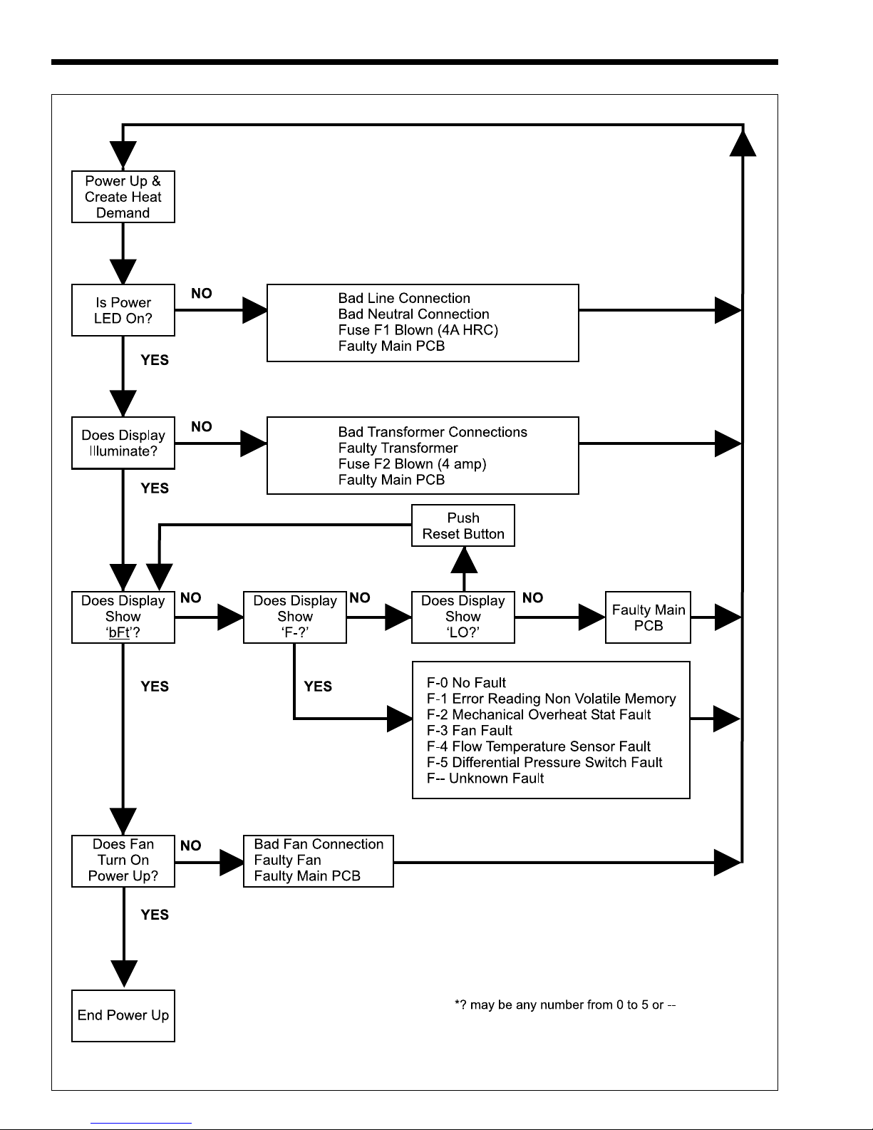
Page 28
LAARS HEATING SYSTEMS
POWER UP
F AULT TREE
Page 29
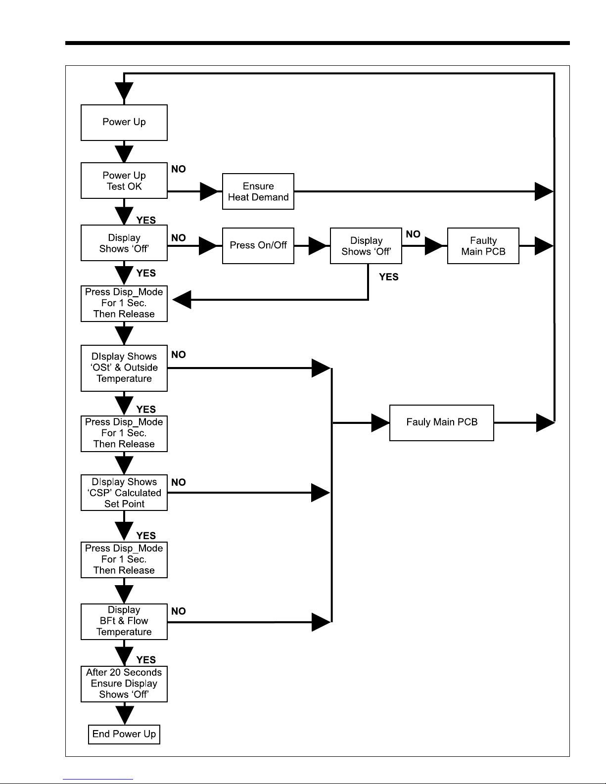
SUMMIT BOILER OR WATER HEATER
Page 29
SYSTEM TEMPERATURES
F AULT TREE
Page 30
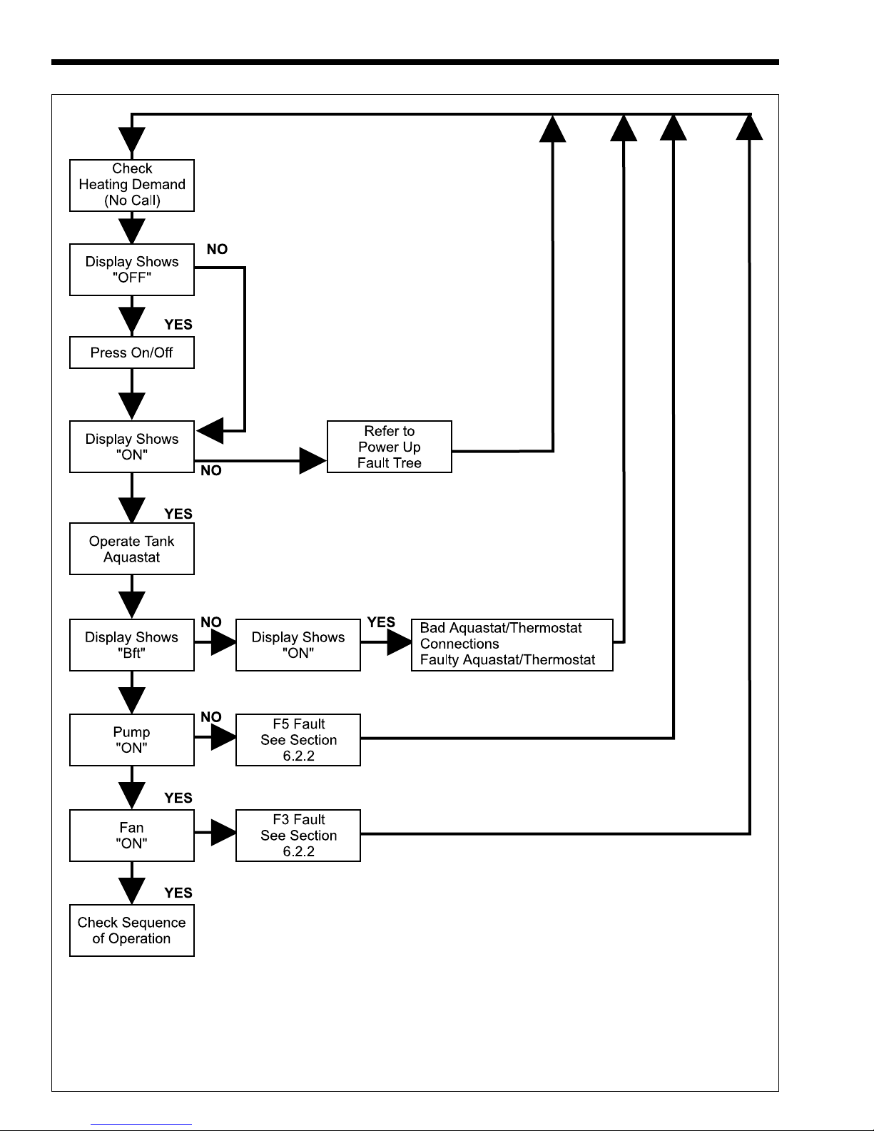
Page 30
LAARS HEATING SYSTEMS
W ATER/SP ACE HEATING
F AULT TREE
NOTE: The word "Thermostat" is used for all space
heating control contacts such as zone valve end
switches, circulator relay contacts, etc.
Page 31
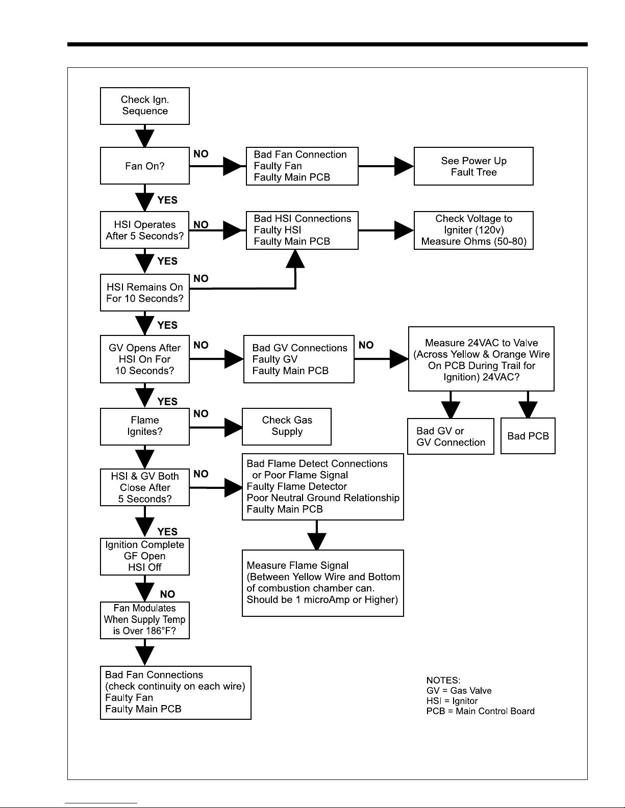
SUMMIT BOILER OR WATER HEATER
Page 31
IGNITION FAULT TREE
Page 32

Page 32
LAARS HEATING SYSTEMS
8.6.2 Gas Valve Regulation
Gas valve regulation problems can also cause
delayed ignitions. See Sections 7.2.2 and 7.2.2.1
8.6.3 Defective Burner - occurs on
startup or at burner shutdown
A defective burner can cause a delayed ignition
during operation or at shutdown. If the gas supply
pressure is proper, the gas valve is functioning
properly and the gas valve throttle and offset pressure
are set correctly, the burner should be inspected. For
inspection: remove the blower and blower mounting
piece as one unit. The burner is retained by the blower
mounting piece and may be lifted out of the top of the
chamber after the blower mounting piece and blower
have been removed. There should be
no distortion or
perforations in the burner other than the punched
holes. Replace if indicated.
8.7 Short Cycling
SMB-200/250 Boiler
Because the Summit is a modulating boiler and
its input will decrease when there is a reduction in
heating load, short cycling is greatly reduced. If the
heating load drops below the minimum input of the
boiler for an extended period, the boiler will have a
tendency to short cycle. If short cycling is frequently
experienced, regardless of the control’s attempt to
limit it, the heating load should be redistributed to
control it.
8.8 Short Cycling
SMW-200/250 Water Heater
Short cycling will generally occur only in
combination space heating and water heating
applications when the water heater is operating in the
space-heating mode. Because the Summit is a
modulating water heater and its input will reduce
when there is a reduction in heating load, short
cycling is greatly reduced. If the heating load drops
below the minimum input of the water heater for an
extended period, the water heater will have a tendency
to short cycle. If short cycling is frequently
experienced, regardless of the control’s attempt to
limit it, the heating load should be redistributed to
control it.
If short cycling occurs in a water heater
application, it is probably caused by undersized piping
between the water heater and the Storage Tank or by
some other factor that restricts proper water flow
through the water heater. The cause should be
determined and corrected.
8.9 High Gas Consumption
Appliances operating with an improper air/fuel
ratio are very inefficient and consequently, have very
high gas consumption. Because efficiency is high
when the CO
operating with low CO
appliances) consume more gas. Adjust the CO
is high (or O2 is low), appliances
2
or high O2 (especially LP
2
or O
2
for optimum efficiency. If no combustion analyzing
equipment (CO
adjustment of the air/fuel ratio (CO
or O2) is available then a proper
2
or O2) can not be
2
accomplished. However, by briefly sniffing the flue
gases it is possible to determine if the CO
or O2 is
2
within the proper range. No significant flue gas odor
should be detected when combustion is proper. A
strong piercing smell indicates poor combustion and
generally a lean mixture (low CO
or high O2). Check
2
gas valve/venturi setup (Throttle and Offset
Adjustment – Section 7.2.2.1) and adjust if indicated.
Do not attempt to correct combustion without an
O
or CO2 kit and a Magnehelic® pressure gage.
2
SECTION 9.
Replacement Parts
Description Part Number
1. Thermostat Kit (140°F) 2400-130
2. Pump, Grundfos, UP26-99F - SMB 2400-090**
2. Pump, Grundfos, UP26-99BF - SMW 2400-388***
3. Venturi, Gaskets included 2400-131
4. Exhaust (Flue) Assembly 2400-402
5. Blower 2400-133
6. Gas Valve 2400-134
7. Burner (Flameholder) 2400-135
8. Economizer Coil *
9. Boiler Coil *
10. Combustion Chamber Ass’y 2400-136
Gasket Kit (Not Shown) 2400-137
11. Ignitor/Flame Sensor Ass’y 2400-138
12. Pressure Gauge (75 PSI) - SMB 2400-574**
Pressure Gauge (300 PSI) - SMW 2400-150***
Pressure Relief Valve (50 PSI) - SMB 2400-316**
Pressure Relief Valve (125 PSI) - SMB 2400-097**
Pressure Relief Valve (150 PSI) - SMW 2400-095***
Appliance Control (PCB) 2400-139
Differential Pressure Switch 2400-106
Flue Overheat T’stat (Limit) 2400-058
Sensor, Appliance Discharge 2400-556
Safety Limit 2400-055
Exhaust (flue) Terminal 2400-104
Intake Terminal 2400-102
Wall Flange 2400-100
Propane Conversion Kit 2400-140
2
* Not Sold Separately, Part of 2400-136
** SMB-200/250 Only
***SMW-200/250 Only
Page 33
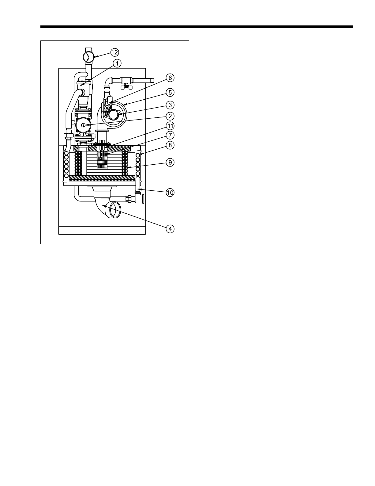
SUMMIT BOILER OR WATER HEATER
Page 33
Figure 21. Parts Identification.
Page 34

Page 34
LAARS HEATING SYSTEMS
Page 35

SUMMIT BOILER OR WATER HEATER
Page 35
Page 36

Waterpik Technologies, Inc.
6000 Condor Drive, Moorpark, CA 93021 • 805.529.2000 • FAX 805.529.5934
20 Industrial Way, Rochester, NH 03867 • 603.335.6300 • FAX 603.335.3355
480 S. Service Road West, Oakville, Ontario, Canada L6K 2H4 • 905.844.8233 • FAX 905.844.2635
H2212100D
www.laars.com Litho in U.S.A. © Laars Heating Systems 0310 Document 1163D
 Loading...