

Page 1
Felix Storch, Inc.
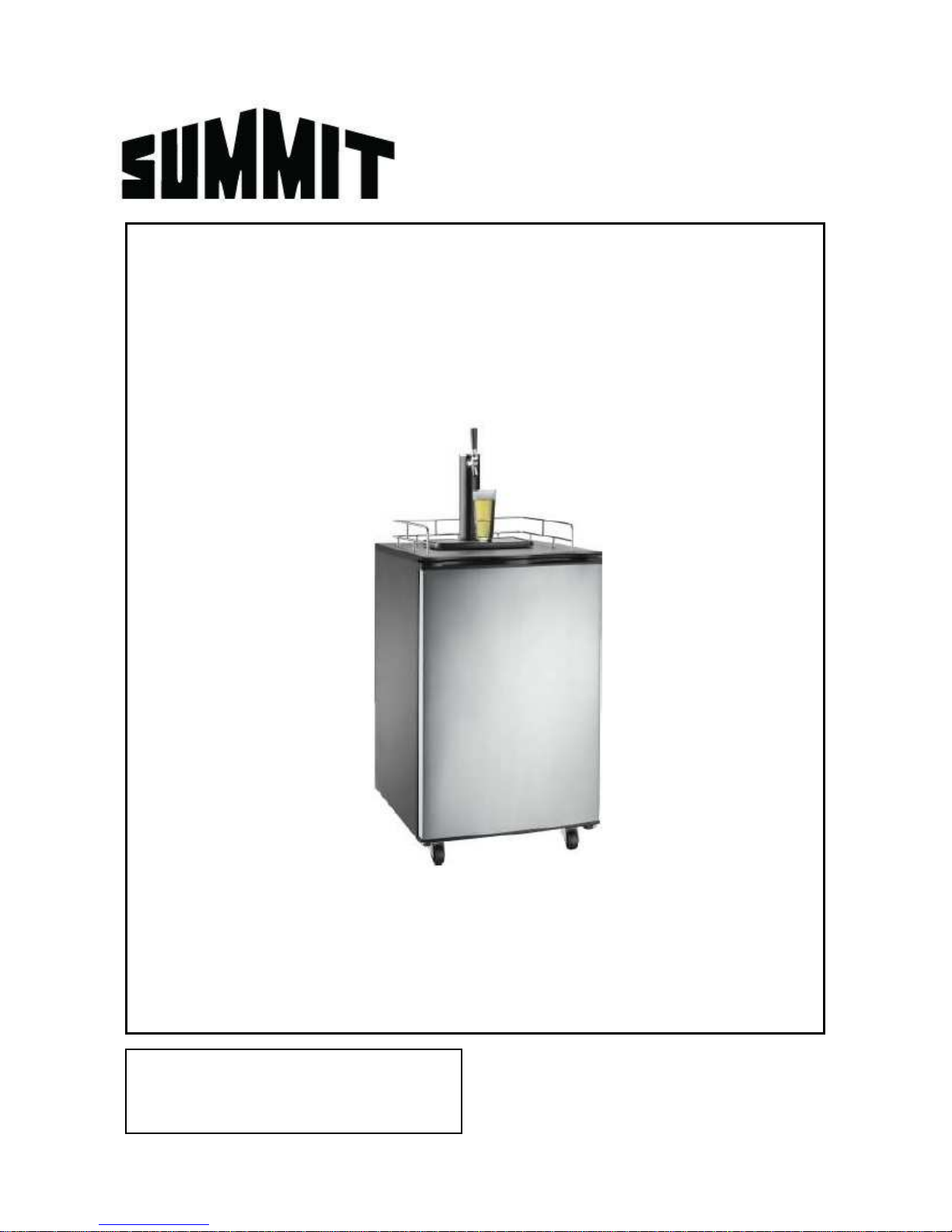
BEER DISPENSER
Model SBC570B
BEFORE USE, PLEASE READ AND FOLLOW ALL SAFETY RULES AND OPERATING INSTRUCTIONS.
Write Serial No. (from back of unit) here:
________________________________
Instruction Manual
770 Garrison Avenue
Bronx, NY 10474
ww.summitappliance.com
Page 2
IMPORTANT SAFEGUARDS
1. You will need this manual for the safety warnings and precautions, operating, inspection,
maintenance and cleaning procedures, parts list and assembly diagram. Record the Serial
Number (from the back of the unit) on the cover of this manual. Keep the manual in a safe
and dry place for future reference.
2. The warnings, cautions and instructions discussed in this manual cannot cover all possible
conditions and situations that may occur. It must be understood by the operator that common
sense and caution are factors that cannot be built into this product but must be supplied by
the operator.
3. Never use this product for anything but its intended use. Never modify this product. Failure to
comply with the precautions, warnings and recommendations in this manual will nullify your
warranty and may result in injury or even death.
4. Always insure that this beer dispenser is plugged into a grounded outlet with the proper
power supply available.
5. Do not unplug the machine by pulling or tugging on the power cord. Firmly grasp the plug
and remove from the outlet.
6. Make sure the power outlet, plug and power cords are in good condition. Worn, frayed or
damaged plugs, cords and outlets should be replaced or repaired by a certified electrician
who is properly qualified to meet local safety and electrical codes. Power supply cords
should be replaced by the manufacturer.
Avoid using extension cords or 3-prong adaptors.
7. To reduce the risk of electrical shock or fire, make sure your unit is properly grounded. Never
tamper with, remove or cut the grounding pin! The wall outlet used with this beer dispenser
MUST be properly grounded. If you do not have a grounded outlet, have one installed by a
certified electrician who is properly qualified to meet local safety and electrical codes.
8. Make sure your machine is unplugged when you conduct any maintenance or repair. A
qualified service technician should always perform service or repair.
9. This product is not intended for commercial use.
10. Do not cover the power cord. Do not immerse cord in water or use in high traffic areas. Do
not run cord over carpets or heating sources or elements. Never use the appliance with
damaged cords or plugs.
11. This product is intended for upright, free-standing use only. Do not install in a cabinet or
enclosed space.
12. Do not operate with missing or broken parts.
13. This product is intended for indoor use only. Do not use outdoors.
14. Only qualified repair personnel should perform generator service. Service or maintenance
performed by unqualified personnel could result in injury.
15. Do not operate this beer dispenser in explosive atmospheres, such as in the presence of
flammable liquids, gases or dust.
16. Do not tamper with or modify the controls.
17. Do not roll a loaded beer dispenser over carpeting. Make sure your unit is empty before
moving it.
IMPORTANT – All persons who will operate this equipment
must read and become thoroughly familiar with all
operating procedures and safety precautions. Misuse
of this equipment may result in personal injury, death,
or property damage.
1
Page 3

18. KEEP UNIT UPRIGHT when transporting. Do not allow to tilt past 45 degrees. Do not upend
or turn upside down.
19. WARNING! Children must be supervised around this machine. Make sure that children
know that this beer dispenser is NOT A TOY. Close door during operation and leave closed
at all times when children are present.
WARNING: EXTENSION CORDS
Because of inherent dangers from faulty or inferior cords, avoid the use of extension cords.
When you cannot avoid their use, be sure that the cord is a 3-wire cord with a 3-prong
grounded plug. The cord should be rated for AT LEAST 1875 watts and a No. 14 AWG
minimum size.
DANGER: RISK OF CHILD ENTRAPMENT
If you are disposing of this machine, we recommend that you remove the door but leave the
shelves in place to reduce the risk of injury to children. DO NOT ALLOW CHILDREN TO
BECOME TRAPPED.
ALWAYS supervise children when using this product when they are present. At all times be
sure that children are not playing with the unit.
LOCATION RECOMMENDATIONS
1. INDOOR USE ONLY. DO NOT ATTEMPT TO USE OUTDOORS.
2. INTENDED FOR UPRIGHT, FREE-STANDING USE ONLY. Do not install in cabinet or
enclosed space.
3. Get the most out of your beer dispenser! To maximize efficiency and long life, use near a
proper electrical outlet and ensure that there is adequate ventilation and clearance around
the unit. Allow at least 5 inches clearance around all sides of the beer dispenser.
Dimensions: 21.3"W x 26.6"D x 33.2"H (with casters)
4. Avoid locations where this unit will be in contact with heating elements or direct sunlight.
CO2 SAFETY PRECAUTIONS, WARNINGS & DANGER NOTICES
1. DANGER! Carbon dioxide is a potentially dangerous gas. Canisters or cylinders are under
pressure and proper handling is essential for safety. Familiarize yourself with canister
installation and replacement before operating this unit. HANDLE WITH CARE. Never jostle,
toss or treat cylinders roughly. If you experience headache or difficulty breathing, a leak may
be occurring; open windows and doors to ventilate the area and leave immediately.
2. INTENDED FOR UPRIGHT, FREE-STANDING USE ONLY. Do not install in cabinet or
enclosed spaces.
3. Store CO
cylinders away from heat or explosive gases. Keep in a cool, dry space (lower
2
than 70°F) and chain canisters upright to avoid tipping or knocking. Always wear gloves and
safety glasses when around chemicals.
4. Review and follow instructions for changing CO
cylinders. NEVER CONNECT A CO2
2
CANISTER DIRECTLY TO THE UNIT. To avoid potential explosion that could result in grave
injury or even death, ALWAYS CONNECT THE CANISTER TO THE CO
There are two safety valves, located separately. One is in the regulator and one on the CO
REGULATOR.
2
2
canister. DO NOT REMOVE VALVES, AND DO NOT EXCEED 60 PSI.
5. DO NOT ATTEMPT TO REFILL CO
CANISTERS! Refills are available where most
2
canisters are sold (see page 6 for more information).
2
Page 4

TABLE OF CONTENTS
Important Safeguards ................................................................................... 1-2
Technical Information ...................................................................................... 3
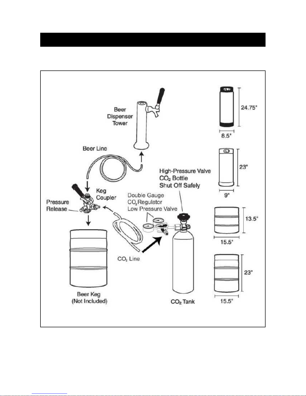
Beer Dispenser Flow and Parts ....................................................................... 4
Beer Dispenser Assembly ............................................................................ 5-7
Caster Assembly .................................................................................. 5
Guardrail Assembly .............................................................................. 5
Beer Tap Installation ............................................................................. 5
CO
CO
How to Tap a Beer Keg ................................................................................... 8
Operation, Maintenance & Storage ................................................................. 9
Accessories (Parts List) ................................................................................. 10
Limited Warranty ........................................................................................... 11
Regulator Installation .................................................................... 6
2
Regulator & Tap Connection Examples ........................................ 7
2
TECHNICAL INFORMATION
Capacity: 6.0 cubic feet
Electrical Input: 115VAC ~ 60Hz
Rated Current: 1.9A
High Side Pressure: 300psi
Low Side Pressure: 88psi
Refrigerant: R134a, 2.82 oz.
Net Weight: 88.2 lbs
Unit Dimensions: 21.3"W x 26.6"D x 33.2"H
dispenser tower)
Model: SBC570B
(with casters but without beer
3
Page 5
BEER DISPENSER FLOW AND PARTS
SAVE THESE INSTRUCTIONS
4
Page 6
BEER DISPENSER ASSEMBLY
Be sure you have a thorough familiarity with the
assembly and installation process before turning
on your beer dispenser.
NOTE: Once casters are assembled, place your
unit in an upright position and allow it to sit for at
least 8-10 hours before plugging into an outlet.
This will allow the refrigerant to settle before
operation.
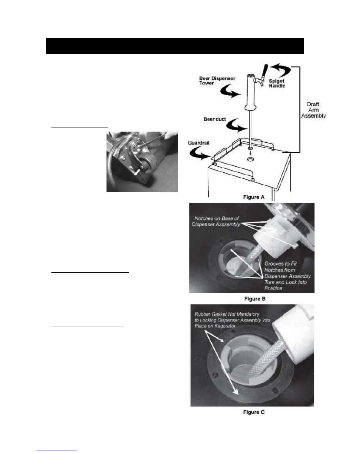
CASTER ASSEMBLY
1. Remove every-
thing from the
cabinet and lay
the unit on a
clean, dry and
padded surface.
2. Install casters
into holes on
bottom of unit
as shown and
tighten with a wrench. Two of the four casters
provided are equipped with locks to prevent
slippage of the keg on smooth surfaces such
as hardwood floors, linoleum or tile. These
casters should be installed on the front of
the unit.
3. Once all four casters are attached, return the
beer dispenser to an upright position and allow
to remain for at least 8-10 hours. (See Note
above.)
GUARDRAIL INSTALLATION
To install the guardrail,
1. Place the guardrail on top of the beer
dispenser and line up the feet of the guardrail
with the holes on top of the cabinet.
2. Using the screws provided, secure each foot to
the cabinet.
BEER TAP INSTALLATION
To install the beer tap, first line up the draft arm
notches with the notches in the hole in the top of
the beer dispenser. Feed the arm into the hole,
making sure that the notches are aligned properly.
Slide arm down and twist until the arm is secure.
(No screws or fasteners are necessary.)
While not required, we recommend the use of the
black rubber gasket when installing the beer tap.
using the gasket will provide a more secure
seating for the arm assembly. (See figures A, B
and C in the next column.)
5
Page 7
BEER DISPENSER ASSEMBLY, continued
REGULATOR INSTALLATION
CO
2
Proper installation of your CO
regulator and a thorough understanding of CO
canisters are
2
essential to the safe use of this
product. Review and follow
instructions for handling CO
and this section in particular to ensure
your safety and the safety of others.
2
cylinders
2
NEVER CONNECT A CO
2
CANISTER DIRECTLY TO THE
UNIT! To avoid potential explosion
that could result in grave injury or
even death, ALWAYS CONNECT
THE CANISTER TO THE CO
2
REGULATOR.
IMPORTANT! Your CO
canister is
2
shipped to you EMPTY for safety
reasons. You will need to get this
canister filled before you can use your unit. In most areas, you can get canisters filled at:
Ø stores that sell kegs
Ø party stores or convenience stores
Ø fire and welding supply stores.
DO NOT ATTEMPT TO REFILL CO
CANISTERS YOURSELF!
2
DANGER! Carbon dioxide is a potentially dangerous gas. Canister or cylinders are under
pressure and proper handling is essential to safety. ALWAYS HANDLE WITH CARE!
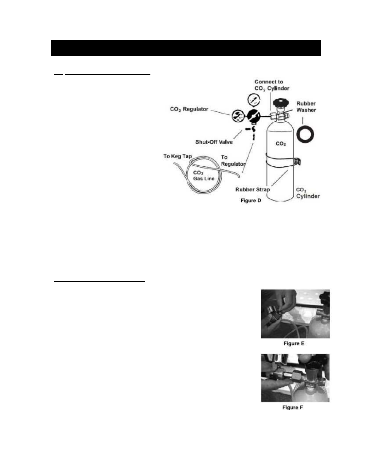
To install the dual-gauge regulator
1. Insert the end of the CO
2
:
line with the green coupler onto the bottom
end of the regulator. (See Figure D above and Photo 1, next page.)
Secure line to regulator by tightening the green coupler.
2. Next, insert the black rubber washer that comes with this unit into the
attachment nut on the regulator (as shown in figure E).
3. Connect the regulator to the canister by screwing the attachment nut
onto the canister valve (see Figure F). Tighten with an adjustable
wrench (not provided), but DO NOT OVERTIGHTEN.
4. Secure the canister with the rubber restraining strap (on side of beer
dispenser cabinet) as shown in Figure D. Be sure to situate the canister
so that the gauges are easily readable and the shut-off valves are easily
accessible.
See following page for examples of correct connections.
SPECIAL PRECAUTIONS: Ensure that the safety devices for your
pressurized system are installed and remain installed. Once installed,
NEVER remove the rubber washers in the regulator attachment nut to the
canister or in the tap mechanism. NEVER bypass these safety features.
Failure to comply will void your warranty and could result in serious injury or death!
6
Page 8
BEER DISPENSER ASSEMBLY, continued
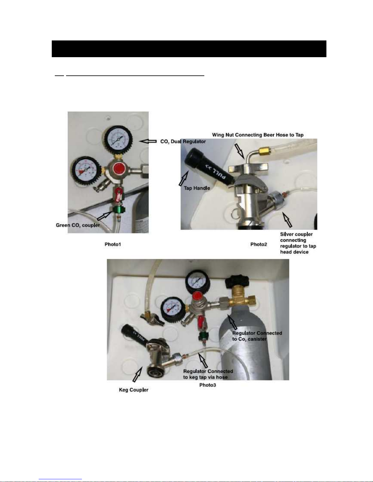
REGULATOR & TAP CONNECTION EXAMPLES
CO
2
PLEASE NOTE: Your CO
the regulator (green coupler) and the tap connection (silver coupler). The photos below show
correct connections.
hose comes equipped and assembled with coupling connections for
2
7
Page 9
HOW TO TAP A BEER KEG
INSTALLING KEG TAP ON SINGLE BARREL TYPE KEG
This beer dispenser's coupler is compatible with a 1/4 pony keg sized barrel and a 1/2 barrel full
size (U.S.A.). The beer dispenser is capable of holding a 5-gallon cornelius keg and a 5-gallon D
system keg. You may find that you will need to use an alternate keg coupler.
Your CO
of beer.
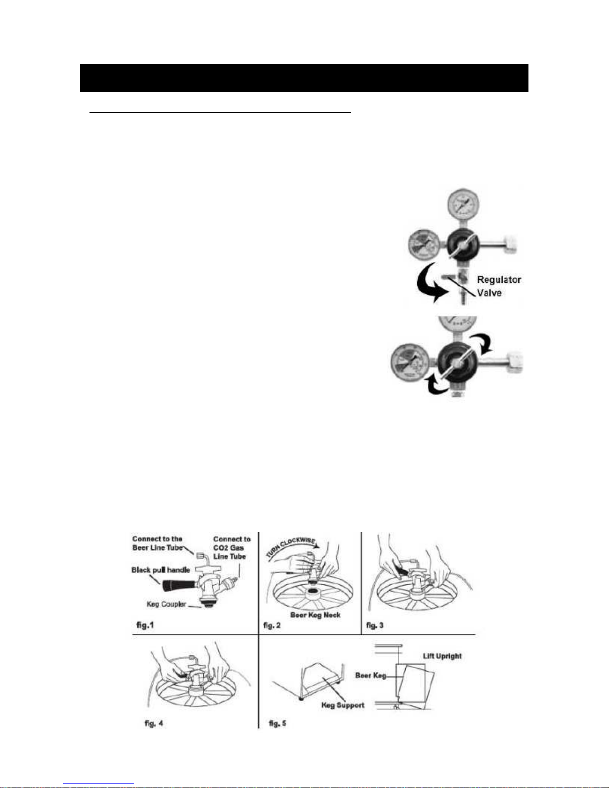
To tap a keg:
1. First be sure that the black dispenser handle of the keg coupler is
2. Insert the keg coupler mechanism into the top of the keg neck
3. Before proceeding, make sure that you insert a black rubber
4. Insert the end of the CO
5. To finalize the connection, pull the black tap handle out and push down until it clicks securely.
6. Carefully tilt the keg onto the lip of the cabinet (using the keg support shown in Fig. 5) and
Note: The left regulator gauge indicates total tank pressure.
canister has a capacity of 2.5 lbs, which will deliver approximately four 15-gallon kegs
2
closed (pushed up, see Fig. 1 below). Also, make sure the tower
dispenser (on top of beer dispenser) handle is closed before
proceeding with tap-to-keg connection.
and perform a quarter-turn clockwise to lock the coupler and keg
together (Fig. 2).
washer into the wing nut connector for the beer line (see page
7, bottom photo) before connecting the line to the tap. Take
off the black protective cap from the tap and screw the wing
nut with the washer to a firm finger-tightness.
line with the silver couple to the CO2
2
connection on the tap. Make sure the coupler connection is
secure. Next, secure the connection between the beer line
and tap with pliers (Fig. 3 and Photo 2, previous page). Make
sure there are no leaks.
There will be an audible click, signaling that the CO
and beer connections have been opened
2
and that your keg is tapped (Fig. 4). Now you may open the regulator valve (top right photo)
and open the valve on the CO
tank itself as well. Set the regulator to read 10-12 psi by
2
turning the regulator handle (bottom photo, right) clockwise.
position slowly into the cabinet body until the door can close. HANDLE CAREFULLY. Do not
jostle or bang keg on CO
canister.
2
8
Page 10
OPERATION, MAINTENANCE & STORAGE
USING YOUR BEER DISPENSER
1. First be sure that you are connected safely to the proper power supply: a 120V, 60Hz, 16 Amp
grounded AC outlet. The cord should be rated for AT LEAST 1875 Watts and a No. 14 AWG
minimum size.
2. Slide the drip tray beneath the spigot to catch excess beer, then pull the tower handle toward
your body to open the tap and dispense beer.
3. To pour beer with a proper head of foam, tilt the glass at a 45 degree angle until
approximately 2/3 full, then straighten the glass and finish pouring beer.
Note: If beer does not dispense, check previous sections on regulator hookup and tapping the
keg.
If your beer is running too slowly, adjust the pressure on the regulator judiciously (DO NOT
EXCEED 12 PSI).
Condensation on the spigot or tap is normal.
STORING YOUR BEER DISPENSER
1. To prevent ice buildup on the inside of the cabinet, set the temperature control to MID or LOW
if you live in a cold area. This unit does not self-defrost. The temperature control is located
inside the beer dispenser.
2. If you do not expect to use your beer dispenser for an extended period of time, rinse the beer
line to prevent mold or bacterial buildup which could cause illness.
3. Never use sharp objects in your beer dispenser. If you are storing your machine, be sure to
prevent children from playing in or around the unit.
DANGER! Children can become trapped in an unsecured and unsupervised environment.
CLEANING AND MAINTENANCE
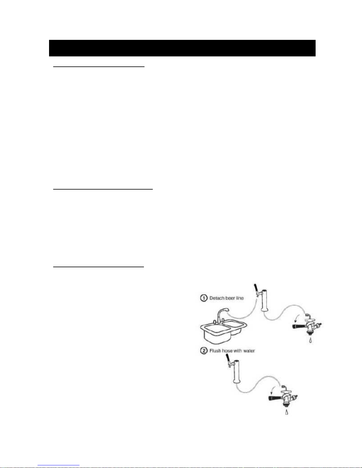
To clean the lines and tap, first:
1. TURN OFF THE CO
2. Next, wipe the outside of the machine, clean drip
tray and around guardrail. Clean the inside of
the cabinet by wiping with a damp cloth. Clean
gasket on door to help eliminate trapped, spilled
beer which could produce mold and mildew.
3. Disconnect the beer hose from the tap coupler
and twist dispenser faucet carefully off the top of
the beer dispenser.
4. Set the dispenser handle to the open or down
position before flushing, then position the faucet
over a sink and hold the beer line under running
water for approximately 5 minutes, allowing the
water to flush out the faucet head. This will also
help eliminate trapped, spilled beer which could
produce mold and mildew.
5. Reconnect beer line and dispenser faucet when
done or leave disconnected if you plan to store
for a long period.
.
2
9
Page 11
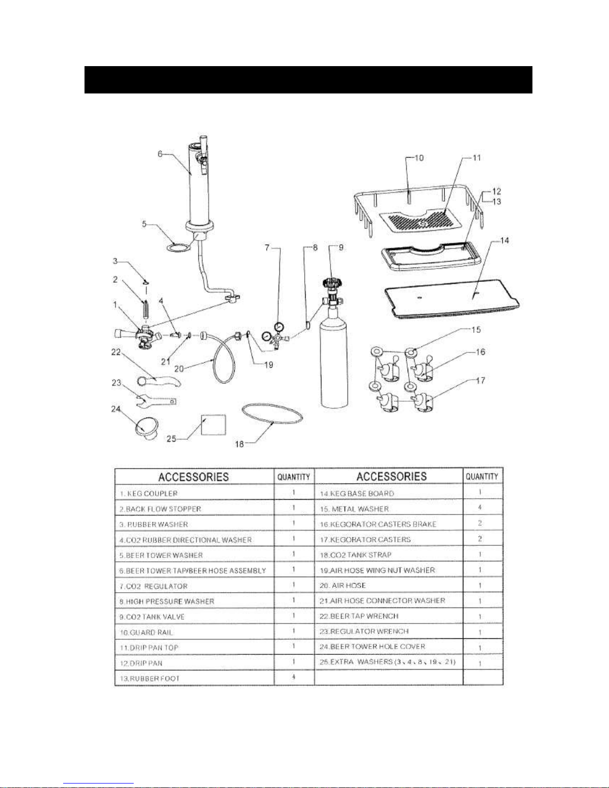
ACCESSORIES
10
Page 12
LIMITED WARRANTY
FELIX STORCH, INC.
www.summitapp
liance.com
ONE-YEAR LIMITED WARRANTY
Within the 48 contiguous United States, for one year from the date of purchase, when this
appliance is operated and maintained according to instructions attached to or furnished with the
product, warrantor will pay for factory-specified parts and repair labor to correct defects in
materials or workmanship. Service must be provided by a designated service company. Outside
the 48 states, all parts are warranted for one year from manufacturing defects. Plastic parts,
shelves and cabinets are warranted to be manufactured to commercially acceptable standards,
and are not covered from damage during handling or breakage.
5-YEAR COMPRESSOR WARRANTY
1. The compressor is covered for 5 years.
2. Replacement does not include labor.
ITEMS WARRANTOR WILL NOT PAY FOR:
1. Service calls to correct the installation of your appliance, to instruct you how to use your
appliance, to replace or repair fuses or to correct wiring or plumbing.
2. Service calls to repair or replace appliance light bulbs or broken shelves. Consumable parts
(such as filters) are excluded from warranty coverage.
3. Damage resulting from accident, alteration, misuse, abuse, fire, flood, acts of God, improper
installation, installation not in accordance with electrical or plumbing codes, or use of products
not approved by warrantor.
4. Replacement parts or repair labor costs for units operated outside the United States.
5. Repairs to parts or systems resulting from unauthorized modifications made to the appliance.
6. Expenses for travel and transportation for product service in remote locations.
7. The removal and reinstallation of your appliance if it is installed in an inaccessible location or
is not installed in accordance with published installation instructions.
DISCLAIMER OF IMPLIED WARRANTIES;
LIMITATION OF REMEDIES
CUSTOMER'S SOLE AND EXCLUSIVE REMEDY UNDER THIS LIMITED WARRANTY SHALL
BE PRODUCT REPAIR AS PROVIDED HEREIN. IMPLIED WARRANTIES, INCLUDING
WARRANTIES OF MERCHANTABILITY OR FITNESS FOR A PARTICULAR PURPOSE, ARE
LIMITED TO ONE YEAR. WARRANTOR SHALL NOT BE LIABLE FOR INCIDENTAL OR
CONSEQUENTIAL DAMAGES. SOME STATES DO NOT ALLOW THE EXCLUSION OR
LIMITATION OF INCIDENTAL OR CONSEQUENTIAL DAMAGES, OR LIMITATIONS ON THE
DURATION OF IMPLIED WARRANTIES OF MERCHANTABILITY OR FITNESS, SO THESE
EXCLUSIONS OR LIMITATIONS MAY NOT APPLY TO YOU. THIS W ARRANTY GIVES YOU
SPECIFIC LEGAL RIGHTS AND YOU MAY ALSO HAVE OTHER RIGHTS, WHICH VARY
FROM STATE TO STATE.
770 Garrison Avenue
Bronx, NY 10474
Phone: (718) 893-3900
Fax: (718) 842-3093
11
For parts and accessory ordering,
troubleshooting and helpful hints, visit:
www.summitappliance.com/support
 Loading...