

Page 1
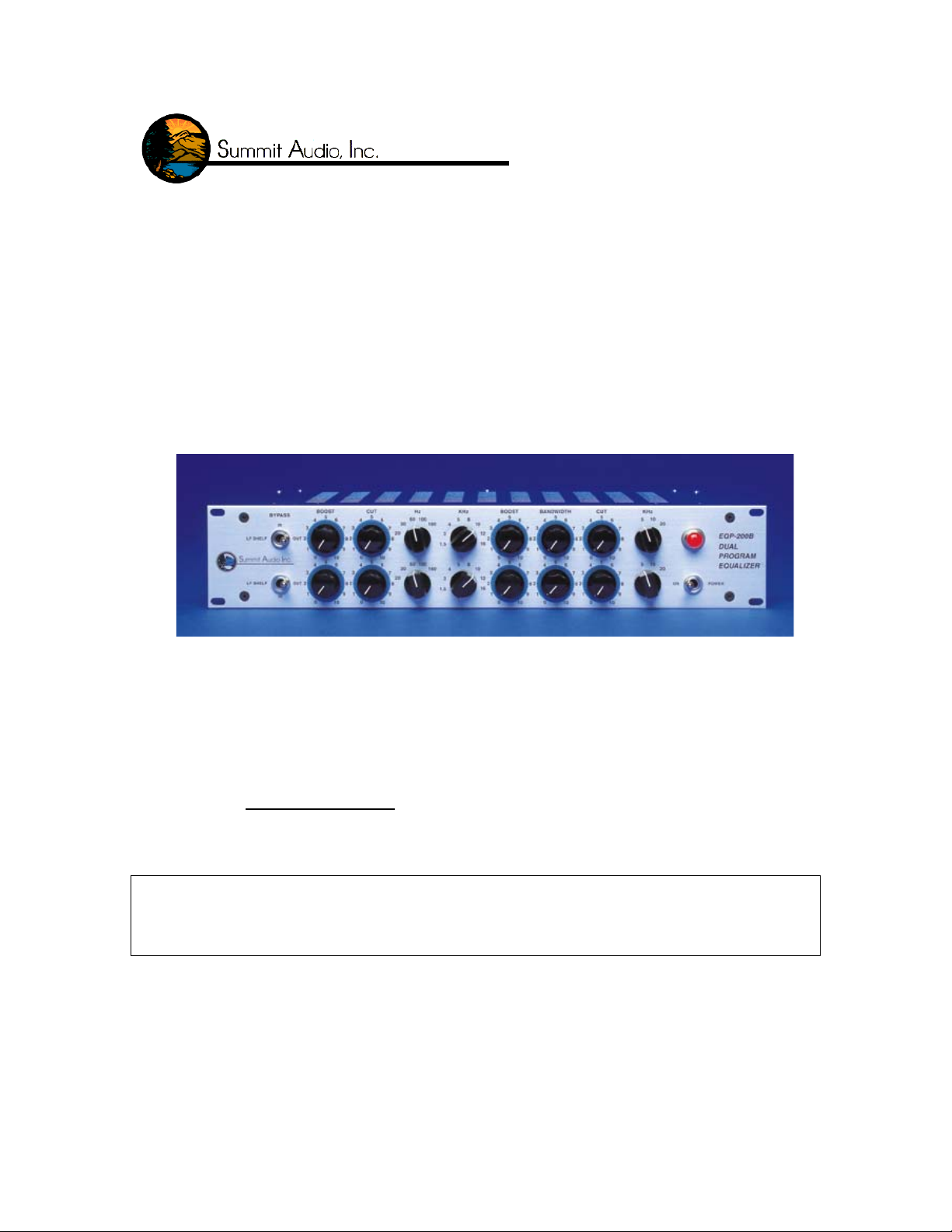
Summit Audio Model EQP-200B
Dual Program Equalizer
Operating Manual
IMPORTANT!: CAREFULLY READ THE ENTIRE INSTRUCTION MANUAL
BEFORE HOOKUP OR OPERATION OF THE EQP-200B.
WARNING!: HIGH VOLTAGE. THIS UNIT CONTAINS NO USER SERVICEABLE
PARTS. SERVICING SHOULD ONLY BE DONE BY QUALIFIED SERVICE
PERSONNEL OR FACTORY. DO NOT OPERATE THE EQP-200B WITH THE
COVERS REMOVED.
Summit Audio
1183 Baltic Suite A
Gardnerville, NV 89410
Copyright 1987, 1997, 2003 Summit Audio Inc. ALL RIGHTS RESERVED. Printed in the
U.S.A. Doc.# 523A00
Page 2

Introduction
The Summit Audio EQP-200B Program Equalizer uses tube and solid state technologies
to produce the warm sounds associated with tubes while providing the reliability of solid
state devices. Based on a Pultec type design, the EQP-200B is a very musical sounding
passive equalizer followed by a vacuum tube amplifier to overcome any gain loss.
Connections are made by using three pin XLR connectors.
Features:
• Two independent channels
• Switch selectable frequencies
• Passive I/O circuits
• In/out/shelf switch
• Extended frequencies and LF shelf
• 105 dB dynamic range
• 990 output stage (balanced or unbalanced)
• Three year warranty
• Transformerless signal path
• Hand crafted in the USA
Having found this manual, carefully unpack the EQP-200B and its power cord. Save the
carton and packing material should it be needed for future shipping. Before powering the
unit, read this manual, observing the cautions for high voltage. Proceed by doing the
following:
• Set the line voltage switch to the proper position
• Determine the proper fuse size by referring to the specifications
• Check for pilot lamp illumination when powered up
Page 3

THE CONTROLS
1. Low Frequency Shelf / In / Out : This three-position toggle switch selects between a low
frequency 6 dB per octave shelving filter starting at 50 Hz, or standard engaged operation, or
bypass mode (which disengages the filters yet still passes through the tubes).
When LF Shelf is engaged the other filters are still accessible.
2. Low Frequency Boost : This potentiometer controls the amount of boost engaged for the 20, 30,
60, 100, 180 Hz frequencies. Maximum boost (a setting of 10) is about 16 dB.
3. Low Frequency Cut : This potentiometer controls the amount of cut engaged for the 20, 30, 60,
100, 180 Hz frequencies. Maximum cut (a setting of 10) is about 20 dB.
4. Low Frequency Select : This five-position rotary switch selects between frequencies of 20, 30,
60, 100, and 180 Hz for which the low frequency boost and cut controls have effect.
5. Mid-High Frequency Select : This eight-position rotary switch selects between frequencies of
1.5k, 3k, 5k, 8k, 10k, 12k, and 16k Hz for which the mid-high frequency boost control has effect.
6. Mid-High Frequency Boost : This potentiometer controls the amount of boost engaged for the
1.5k, 3k, 5k, 8k, 10k, 12k, and 16k Hz frequencies. Maximum boost (a setting of 10) is about 20
dB.
7. Mid-High Frequency Bandwidth : This potentiometer controls the “Q” or bandwidth associated
with the boost engaged for the 1.5k, 3k, 5k, 8k, 10k, 12k, and 16k Hz frequencies. It is important
to note that minimum setting (0) imposes the tightest filter and a maximum setting (10) imposes
the broadest filter. When set for maximum bandwidth, the mid-high frequency boost is limited to
boost of about 10 dB.
8. High Frequency Cut : This potentiometer controls the amount of cut engaged for the 5k, 10k,
and 20k Hz frequencies. Maximum cut (a setting of 10) is about 17 dB. The slope of the filter is 6
dB per octave.
9. High Frequency Select : This three-position rotary switch selects between frequencies of 5k,
10k, and 20k Hz for which the high frequency cut has effect.
10. Power : This switches power on and off. Note that the red pilot lamp is illuminated when the unit
is on. (It is possible that over time the bulb in the pilot lamp may burn out, in which case the unit
is still operational, but you won’t be able to tell from the pilot lamp if the unit is on. Please contact
Summit Audio authorized dealers for bulb replacements.)
[Note: The two channels operate as dual mono. Thus, the top controls have no effect
on the bottom channel and vice versa.]
Page 4

1. 3. 5. 7. 9.
0.
2. 6.4. 8. 1
Page 5

Circuit Explanation
The EQP-200B is two independent equalizers. The circuit has an electronically
balanced input stage that is followed by a passive equalizer. The function of the
equalizer can be thought of as three different sections. These are: a low frequency
attenuate and boost section, a high frequency boost section that has an adjustable
bandwidth, and a high frequency attenuate section. This type of equalizer is made of
resistors, capacitors and inductors. The equalizer has approximately a 20dB gain loss
which must be overcome. This gain loss is overcome by the vacuum tube amplifier. The
equalizer circuit feeds the first stage of the tube amplifier and the second stage of the
amplifier has a cathode follower for low output impedance. The cathode follower drives
the discrete 990 output stage. The tubes are operated class A with negative feedback.
The power supply is all solid state and regulated. The tube heaters are D.C. operated.
A Word About Tubes
The tubes that are used in the EQP-200B are selected to give the best possible
performance in the position that they are in on the printed circuit board. Switching them
to different positions will cause performance deterioration on the audio path. Replacing
them with “gold” or high end tube types may not be desirable. In cases that we have
measured, these tubes have shown higher distortion and noise as compared to the tubes
we have selected. In some cases, the so called “gold” or high end tubes have made the
unit unusable. The reason for this is some of the “gold type” tubes are selected for high
distortion in guitar amplifiers. Using gold tubes is no guarantee of better performance.
All of these so called “Brand X” types are selected with 6.3 volts AC on the heaters,
whereas Summit Audio uses 5 volts DC on the heaters for longer tube life and lower
noise. The reduced gain can raise the noise floor, increase distortion, and reduce
headroom.
For proper performance from a tube, the replacements must be selected using 5
volts DC on the filaments. The tubes we use are selected in the circuits that they are used
in to ensure proper operation, long life, and low distortion and noise.
In at least 50% of the cases we have tested, gear that has been used for several
years actually have lower noise and distortion levels than when new. This makes the
question of when to replace tubes difficult to answer. If a tube turns micro-phonic, the
distortion will be obvious and the tube must be replaced. However, tube life will most
likely be greater than 10,000 hours of operation. Tubes are generally very reliable; don’t
replace them just because they are old. In the EQP-200B there are gain adjustments that
will need to be checked when the tubes are replaced, or else the metering could become
inaccurate and the noise floor could change. Replacement should be done on the bench
with a distortion analyzer attached to ensure that the distortion levels are proper and it is
comprised of second order harmonics.
Before replacing the tubes in your EQP-200B, please talk to your dealer, call
Summit Audio, or find a technician who has experience working with tubes and high end
audio equipment.
Page 6

Electrical Connections:
(This EQP-200B is wired as a pin 2 hot device. Units made before March 1
st,
2003 come
factory wired with pin 3 hot.)
Input:
Unbalanced: 3 pin XLR Connector Balanced: 3 pin XLR Connector
Pin 1 – Ground Pin 1 – Ground
Pin 2 – (+) Signal Pin 2 – (+) Signal
Pin 3 – Connect to Pin 1 Pin 3 – (-) Signal
Output:
Unbalanced: 3 pin XLR Connector Balanced: 3 pin XLR Connector
Pin 1 – Ground Pin 1 – Ground
Pin 2 – (+) Signal Pin 2 – (+) Signal
Pin 3 – Connect to Pin 1 Pin 3 – (-) Signal
Note: When running an unbalanced output it is best to connect pin 3 to pin 1 in the
connector that plugs into the EQP-200B.
Allow the EQP-200B to warm up for at least 15 minutes before using it in your
processing chain. The tubes and other circuitry need time to reach an electronic
equilibrium before they will operate at optimal specifications. For the longest life, it is
recommended that you turn off the unit when it is not in use.
Please mount the unit in your rack, making sure that there is sufficient ventilation,
especially on the right and left side of the chassis. The EQP-200B will generate a
significant amount of heat; therefore, it is necessary to have good air flow to prevent
damage to your EQP-200B or any other pieces of gear housed in the rack with it.
The tubes in your Summit Audio EQP-200B have been intensely screened for
desired distortion and gain characteristics. We recommend that you do not replace the
tubes with “guitar amp” tubes. Please consult your dealer about availability of
appropriate replacement tubes. These can also be ordered directly from Summit Audio.
Please fill out the enclosed warranty card. If you have any questions about the operation
of your EQP-200B, please do not hesitate to call our customer service department at 775782-8838 or contact us on the internet at: sound@summitaudio.com.
SPECIFICATIONS
Page 7

Note on specifications: Summit Audio is uncompromisingly committed to excellence. All
of our specifications are made with the latest technology and are UNWEIGHTED
measurements. What does this mean? When measurements are “weighted” (e.g. “A”
weighted, dB (B), dB C weighted, etc.), the measurement devices are basically EQed or
filtered before the measurement is taken. This filtering was developed so that sound
pressure level (SPL) measurements can more nearly match human’s non-linear hearing
characteristics. However, when used in noise, frequency response, and distortion
measurements, weighting will alter the results. Completely flat frequency measurements
are key to giving accurate specifications. Summit Audio devices are the highest quality
professional audio gear and the specifications below are made with the flattest possible
unweighted measurements, giving the most accurate results.
OUTPUT: +4 dBu is the designated operating level. The output is balanced or
unbalanced, using discrete 990 operational amplifiers with an impedance of 75
ohms. The recommended load is 600 ohms or more. Maximum output is +25
dBu.
INPUT: The input is electronically balanced with an input impedance of 20K
ohms.
FREQUENCY RESPONSE: 5 Hz to 100 kHz (balanced output)
PANEL SIZE: Standard 19” by 3.5” (two units of rack space).
DEPTH BEHIND PANEL:10.5” in addition to users I/O cabling.
POWER: 35 watts 115-230 Volt 50 or 60 Hz
COMPONENTS: (3) Selected 12AX7A Vacuum tubes, (4) high reliability
discrete 990 operational amplifiers, (10) integrated circuits, (4) transistors
FUSE SIZE: .5 Amp for 115 VAC, .25 Amp for 230 VAC
SHIPPING WEIGHT: 18 lbs. (8.1 kg)
 Loading...