

Page 1

Summit Audio
ECS-410 Everest
Operation Manual
1ECS-410 EVEREST
Page 2

2 Summit Audio, Inc.
Page 3

ECS-410 EVEREST
Flagship Channel Strip
Operation Manual
© 2008 Summit Audio, Inc.
All Rights Reserved
Version 1.2
Email: everest@summitaudio.com
Summit Audio, Inc.
P.O. Box 326
Gardnerville, NV 89410
Tel: 775-782-8838
3ECS-410 EVEREST
Page 4

4 Summit Audio, Inc.
Page 5

Contents
Introduction ..........................9
Front Panel Overview . . . . . . . . . . . . . . . . . . 11
Connections . . . . . . . . . . . . . . . . . . . . . . . .12
Suggested Connection Scheme . . . . . . . . . . . . . . . . . . . .12
+4 Balanced Outputs (4) . . . . . . . . . . . . . . . . . . . . . . . .12
-10dB Balanced Outputs (2) ......................12
Contents
XLR Microphone Input ...........................13
Front Panel Hi-Z Input ...........................13
Insert Point (mic preamp) .........................13
Side Chain Insert (dynamics) . . . . . . . . . . . . . . . . . . . . . . 13
Stereo Link ...................................14
To “Stereo Link” two units: . . . . . . . . . . . . . . . . . . . . . . .14
A.C. Receptacle ...............................14
TouchPatch™ Routing System .............15
Mz2 - Microphone & Instrument Preamplifier .17
Microphone Preamp Gain Control . . . . . . . . . . . . . . . 17
Pad Switch . . . . . . . . . . . . . . . . . . . . . . . . . . . . . . . . 18
Input Meter ................................18
Hi-Z Input . . . . . . . . . . . . . . . . . . . . . . . . . . . . . . . . . . .18
5ECS-410 EVEREST
Page 6

Contents
TouchPatch Indicator .........................18
Polarity Switch ..............................18
+48V Phantom Power Switch ...................18
Tube/Solid-State Output Switch . . . . . . . . . . . . . . . . . 19
Dc1- Dual Mode Dynamics Control ........20
Gain Control . . . . . . . . . . . . . . . . . . . . . . . . . . . . . . 20
Threshold Control ...........................20
Attack Control ..............................21
Release Control . . . . . . . . . . . . . . . . . . . . . . . . . . . . 21
Compression Type Switch ......................21
Bypass/Link Switch ...........................22
To “Stereo Link” two units: . . . . . . . . . . . . . . . . . . . . . . .22
TouchPatch Indicator .........................22
6 Summit Audio, Inc.
Fe1- Passive Three Band Equalizer .........23
Low Band .................................23
Mid Band .................................23
High Band . . . . . . . . . . . . . . . . . . . . . . . . . . . . . . . . 24
Peak or Shelving Response .....................24
Bypass Switch . . . . . . . . . . . . . . . . . . . . . . . . . . . . . . 24
TouchPatch Indicator .........................24
Db2 - Drive Bus Output and Drive Section . . . 25
Drive Control . . . . . . . . . . . . . . . . . . . . . . . . . . . . . . 25
Master Output Level . . . . . . . . . . . . . . . . . . . . . . . . . 26
Output VU Meter . . . . . . . . . . . . . . . . . . . . . . . . . . . 26
Tube/Solid-State/Bypass Switch . . . . . . . . . . . . . . . . . 26
Page 7

Bus Overload LED ...........................26
Drive LED .................................26
Applications .........................27
Vocals ......................................27
Voice Over . . . . . . . . . . . . . . . . . . . . . . . . . . . . . . . . . .28
Acoustic Guitar . . . . . . . . . . . . . . . . . . . . . . . . . . . . . . .29
Bass . . . . . . . . . . . . . . . . . . . . . . . . . . . . . . . . . . . . . . .30
Electric Guitar Direct . . . . . . . . . . . . . . . . . . . . . . . . . . .32
Kick Drum ...................................33
Mic’ed Guitar Amp .............................34
Keyboard ....................................36
Tips and Tricks . . . . . . . . . . . . . . . . . . . . . . . 37
Contents
Need More Distortion? . . . . . . . . . . . . . . . . . . . . . . . . .39
Block Diagrams . . . . . . . . . . . . . . . . . . . . . .42
Input/Output & TouchPatch Switching . . . . . . . . . . . . . 42
Mz2 - Microphone and Instrument Preamplifier . . . . . . 43
Dc1 - Dual Mode Dynamics Control ..............44
Fe1 - Passive Three Band Equalizer ...............45
Db2 - Drive Bus Master Output & Drive Section ......46
Electrical Connections ..................47
Balanced 3-pin XLR . . . . . . . . . . . . . . . . . . . . . . . . . . . .47
Balanced 1/4” (TRS) jack . . . . . . . . . . . . . . . . . . . . . . . .47
1/4” (TRS) jack ................................47
Specifications ........................48
7ECS-410 EVEREST
Page 8

Contents
8 Summit Audio, Inc.
Page 9

Introduction
Congratulations on your purchase of the Summit Audio ECS-410
Everest Channel Strip, a distinctly different, four section analog
processor and microphone preamp, ideal for tracking and
processing your most important signals.
Each section is completely independent with its own fully balanced
I/O and the ability to route each section together internally using
TouchPatch™ a unique and amazingly intuitive routing system.
You have four complete processors combined into one superlative
master channel strip.
Introduction
Mz2• - Microphone and Instrument Preamplifier
Dc1 - Dual Mode Dynamics Control•
Fe1 - Passive Three Band Equalizer•
Db2 - Drive Bus Master Output and Drive Section•
Features
Tube or Discrete Transistor Mic Preamp w/Jensen Transformer•
Passive LC Equalizer for unparalleled warmth and flavor •
Dual Mode Dynamics using Summit Classic Design•
DriveBus Transistor or Dual Tube Overdrivable Output•
TouchPatch™ Single Touch Routing•
Independent Balanced I/O on All Sections•
Hand Crafted in the U.S.A.•
9ECS-410 EVEREST
Page 10

Introduction
Unpacking
Carefully unpack the ECS-410 Everest and its power cord. Save
the carton and packing material for possible future use. Before
powering up the unit, read this manual and make sure the power
selector switch is set to the correct voltage for your part of the
world.
Important Warranty Information
For your 3 year warranty, register your ECS-410 Everest online
today at www.summitaudio.com.
10 Summit Audio, Inc.
Page 11
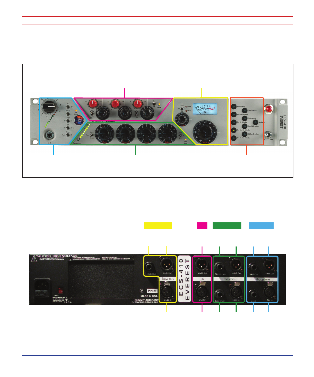
Front Panel Overview
Mz2
Mic/Instrument Preamp
Db2
DriveBus Output
Dc1
Dual Mode Dynamics
Fe1
Passive 3-Band EQ
TouchPatch
Signal Routing
DriveBus EQ Dynamic Preamp
-10 dB
Out
+4 dB
Input
+4 dB
Input
Side
Chain
+4 dB
Input
Insert Mic
Input
+4 dB
Out
+4 dB
Out
Stereo
Link
+4 dB
Out
-10 dB
Out
+4 dB
Out
Front Panel Overview
Rear Panel Overview
11ECS-410 EVEREST
Page 12

Connections
Connections
Suggested Connection Scheme
The ECS-410 will normally be connected with every input and
output point wired into your balanced analog Patchbay. This
hookup allows convenient access to the plentitude of inputs
and outputs and provides the greatest flexibility.
Because you have the power of TouchPatch, you may be
tempted to connect just a single channel of input and output.
Although this simple setup is fine while you get acquainted
with this fine instrument, you’ll be missing out on a lot of
potential connections.
Note: You can use all inputs
and outputs at the same time
for versatility.
Important: For proper
operation of the ECS-410 (or
any vacuum tube device for
that matter), allow the unit to
warm up with power on for 15
minutes before use.
Important: Do not block
the cooling holes and allow
adequate ventilation.
+4 Balanced Outputs (4)
Each section of the ECS-410 has its own +4dBu XLR output. All
four outputs are balanced and low impedance, compatible with
professional recording and audio equipment.
Balanced outputs provide superior noise immunity in the studio
and when using long cable runs.
The output connector is wired as follows:
Pin 1= Ground, Pin 2 = (+) Signal, Pin 3 = (-) Signal.
-10dB Balanced Outputs (2)
The Microphone Preamp and the DriveBus Output sections both
have an additional -10dBV, 1/4” balanced (TRS) output designed
to interface with your recording device, compressor or EQ.
(0 VU on the output VU meter corresponds to +4dBu)
12 Summit Audio, Inc.
Page 13
Connections
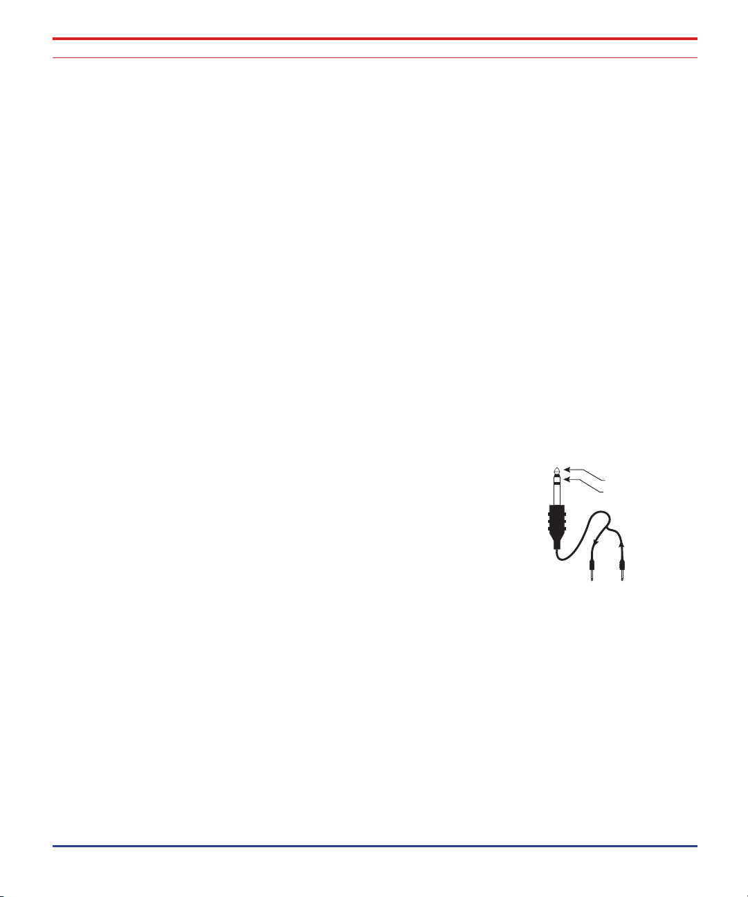
Signal Out of Preamp
Signal Return to Preamp
Tip Ring
INSERT CABLE
Signal is sent out on tip of plug and
returned to mixer via ring of plug.
XLR Microphone Input
This is a balanced, low level input designed for microphones. The
gain can be adjusted from -20dB to +60dB using the front panel
Gain control and the -20 dB Pad switch.
48-volt phantom power can be applied to this jack using the front
panel switch.
Front Panel Hi-Z Input
This is a 10K Ohm impedance, unbalanced instrument level input
controlled by the front panel Gain control. This tube amplified
input is designed for electric instruments such as guitar or bass,
although higher level signals, such as a synthesizer, can also be
connected here. The Hi-Z input overrides the Microphone input
whenever a plug is inserted into this jack.
Insert Point (mic preamp)
The TRS insert jack allows you to insert another processing device
into the microphone preamp circuitry after the transformer and
gain control, but before the preamp (solid-state or tube) output
stage. An insert cable of the type required is shown at right.
Note: The Hi-Z input overrides
the Microphone input whenever a plug is inserted into the
Hi-Z jack.
This jack can also be used as another input or output.
(Tip is output; Ring is input.)
Side Chain Insert (dynamics)
The side chain insert jack allows an external signal (such as an
equalizer) to be inserted in order to control the Dynamics section
Gain Cell from a separate signal.
For example, by inserting an equalizer here (the Fe1 is handy), you
can perform frequency selective compression such as de-essing or
de-booming. A separate signal can also be connected to the tip
of the jack in order to “duck” the signal running through the Dc1.
13ECS-410 EVEREST
Page 14

Connections
The TRS jack wiring on the Dynamics insert is as follows: the Tip is
the output of the Gain Cell, and the Ring connects to the input of
the Sidechain Processor.
Stereo Link
Link mode allows the Dynamics section of two ECS-410 Everest
units to be linked to process stereo signals. When two units
are linked in this way, the leveling action will be the same on
both units. When stereo linked, the channel providing the most
compression will always control the other unit.
To “Stereo Link” two units:
Connect a standard 1/4” mono audio cable between the 1.
“Stereo Link” jack of two ECS-410 units.
Set the controls on both units the same.2.
14 Summit Audio, Inc.
Set the BYPASS switch on the front panel to LINK. 3.
A.C. Receptacle
The ECS-410 Everest is factory wired for either 100, 115 or 230
Volts AC. Before connecting AC power make sure the unit is wired
for the correct voltage used in your country.
Page 15
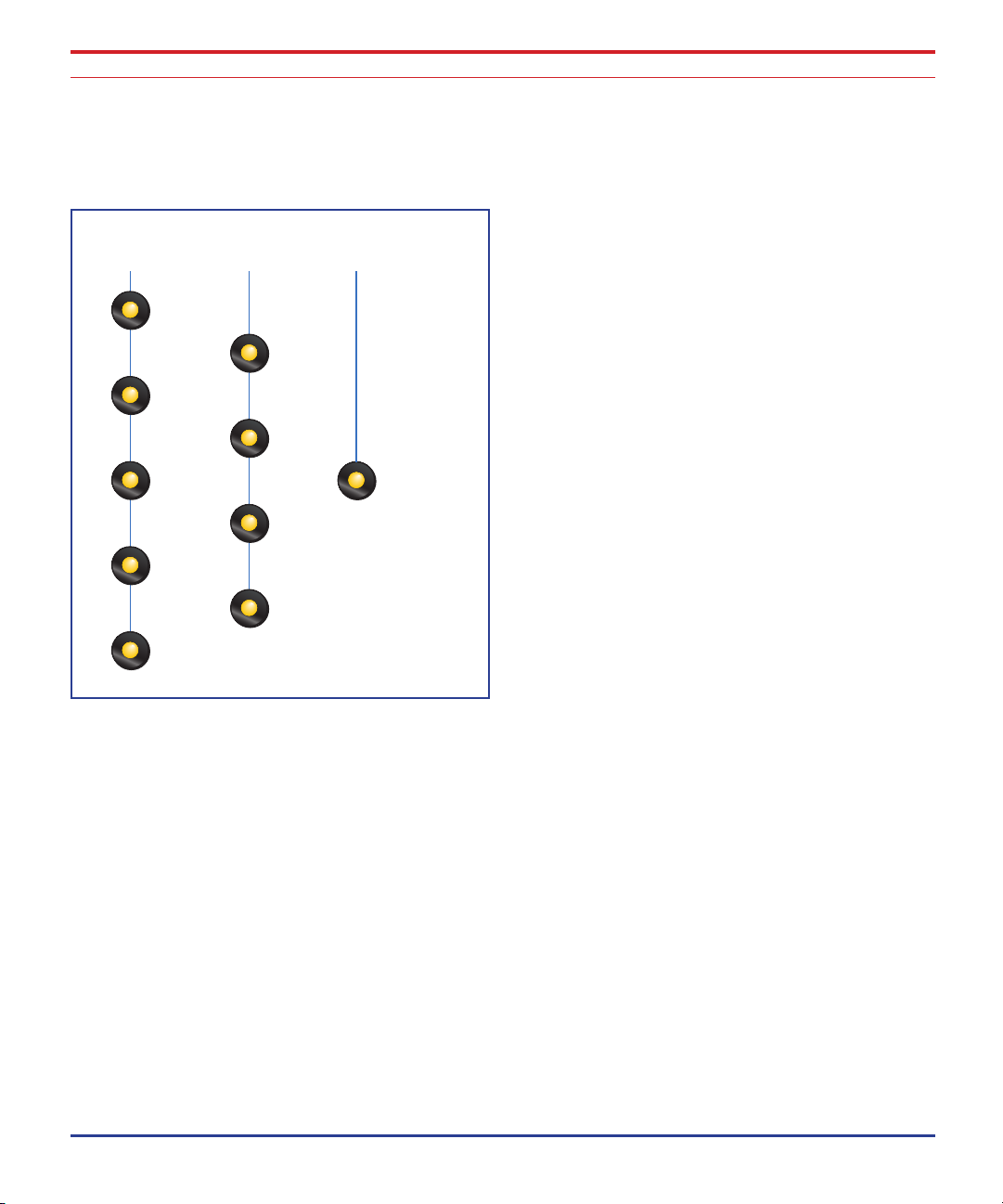
TouchPatch™ Routing System
No Route
Pre-DriveBus
Pre-Dyn-DriveBus
Pre-EQ-DriveBus
Pre-Dyn-EQ-DriveBus
Pre-EQ-Dyn-DriveBus
Mz2
Preamp
Dyn-DriveBus
EQ-DriveBus
Dyn-EQ-DriveBus
EQ-Dyn-DriveBus
No Mx2
Preamp
TouchPatch
Bypass
TouchPatch™ Routing System
Unique to the ECS-410, the TouchPatch™ routing allows you to
route any section to and from any other section with a touch of a
single button. TouchPatch controls what is feeding DriveBus and
anything not routed is available to be used individually from the
back panel.
The first row of five buttons include the Mz2 Preamplifier as the
first processor in the chain. (The Db2 DriveBus is always last.)
The second row of four buttons have all the remaining effects
combinations but without the Mz2 Preamplifier.
The No Route button turns off all routing to the DriveBus, allowing
you to use each processor separately.
g TouchPatch makes setup
and experimentation a breeze
since all the patching is automatic.
In addition, the audio signals
remain on the circuit board
without being routed through
noisy connectors and switches.
15ECS-410 EVEREST
Page 16
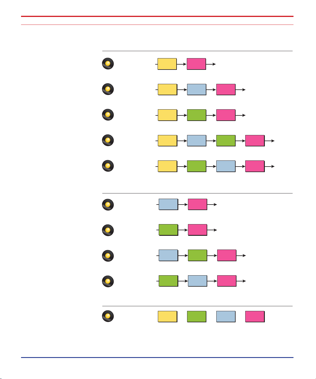
TouchPatch™ Routing System
Pre-DriveBus
Pre-Dyn-DriveBus
Pre-EQ-DriveBus
Pre-Dyn-EQ-DriveBus
Pre-EQ-Dyn-DriveBus
Preamp
Output/
Drive
Preamp Dynamics
Output/
Drive
Preamp EQ
Output/
Drive
Preamp Dynamics EQ
Output/
Drive
Preamp EQ Dynamics
Output/
Drive
No Route
Preamp EQ Dynamics
Output/
Drive
Dynamics
Output/
Drive
EQ
Output/
Drive
Dynamics EQ
Output/
Drive
EQ Dynamics
Output/
Drive
Dyn-DriveBus
EQ-DriveBus
Dyn-EQ-DriveBus
EQ-Dyn-DriveBus
Preamp Input
No Preamp
Independent Processors
16 Summit Audio, Inc.
Page 17

Mz2 - Microphone & Instrument Preamplifier
Mz2 -
Microphone & Instrument Preamplifier
-20dB Pad
Preamp
Gain
Input
Meter
High
Impedance
Input
TouchPatch
Indicator
Polarity
Phantom
Power
60Hz High
Pass Filter
Tube or
Solid State
Output Select
The Mz2 is a exotic blend of discrete, solid-state and tube circuitry
designed to offer the full range of features in a microphone and
instrument preamplifier. An interstage Jensen line transformer
adds warmth and character. Each stage of the Mz2 has been
carefully crafted for the ultimate in performance and sound. With
the Mz2, you get the best of both worlds, solid-state clarity and
vacuum tube tone.
Microphone Preamp Gain Control
This control adjusts the gain of the microphone preamplifier from
0dB to +60dB. Set the input gain to get a strong level on the
input meter without turning on the top red clip indicator.
17ECS-410 EVEREST
Page 18

Mz2 - Microphone & Instrument Preamplifier
Pad Switch
This switch engages or disengages a –20dB pad to set the input
sensitivity of the microphone input.
Input Meter
The 10-segment input meter indicates the signal level at the input
of the preamp. The top red LED indicates hard clipping.
Hi-Z Input
This input can be used to mix in a musical instrument or other
high impedance signal. The Hi-Z input is always routed to the
tube section.
TouchPatch Indicator
Warning: Some microphones (notably ribbon mics)
cannot tolerate phantom power
and may be damaged. Check
the microphone’s specifications
and requirements before using
phantom power.
18 Summit Audio, Inc.
This LED lights to indicate that the Preamp section is routed to the
internal DriveBus.
Outputs of any section are always active, even if routed via TouchPatch. If not routed via TouchPatch inputs as well as outputs are
active.
Polarity Switch
This switch inverts the polarity of the microphone input in order to
compensate for out of phase equipment or wiring.
+48V Phantom Power Switch
This switch enables +48 volt phantom power to the microphone
input. Turn the unit off to bleed off the voltage.
Page 19

Mz2 - Microphone & Instrument Preamplifier
High Pass Filter
To reduce rumble or sub-audio frequencies, you have the option
to enable this virtually transparent high pass filter. The frequency is
fixed at 60Hz with a gentle 6dB/octave rolloff.
Tube/Solid-State Output Switch
This switch selects between a solid-state or vacuum tube preamplifier. Choose SS for ultra-clean-pristine or Tube for more warmth
and color.
19ECS-410 EVEREST
Page 20

Dc1- Dual Mode Dynamics Control
Gain Threshold Attack Release
Bypass/Link
Gain
Reduction
Meter
TouchPatch
Indicator
Compression
Mode
Dc1- Dual Mode Dynamics Control
The Dc1 utilizes Summit’s proprietary compression technology,
with ultra-low noise coupled with smooth, musical operation.
There are 2 modes of operation. Classic mode is a smooth,
signal-dependent compression, perfect for sweetening vocal and
instrument tracks. Tight mode allows a much higher compression
ratio and is perfect for controlling peaks and transients, which
could spoil your recording.
20 Summit Audio, Inc.
Gain Control
The Gain control allows you to boost the output gain of the
compressor in order to make up for the gain reduction and is
adjustable from -6dB to +13.5dB.
Threshold Control
This important control sets the level at which gain reduction
begins. Everything above the threshold level will be brought down
in volume. If the signal falls below the Threshold, no processing
will take place.
Use the Gain Reduction Meter to identify the correct threshold
setting. If you’re trying to trim off just the loudest peaks, set the
Page 21

Dc1- Dual Mode Dynamics Control
threshold so the gain reduction meter only shows compression
during these peaks.
Attack Control
Attack controls how quickly the gain is turned down after the
signal exceeds the threshold. The attack time is variable from 4mS
to 100mS.
An attack setting of about 3 on the scale will delay the onset of
compression long enough to preserve the attack transients in
guitar, bass or drums while allowing the sustain portion of the
sound to be compressed. Use the “Fast” setting to reduce fast
transients.
Release Control
Release controls how fast the gain is returned to its normal setting
after the signal has fallen below the threshold again.
Slower release times are generally used to reduce the so called
“pumping” effect as the compressor turns on and off. Don’t make
the release time too long, however, or the compressor won’t have
time to recover for the next pluck or hit.
In general, the attack and release controls are used to smooth out
the action of the compressor, but they can also be used to create
special effects.
Compression Type Switch
The compressor has two modes:
Classic Mode - soft knee compression with a maximum •
compression ratio of 3:1
Tight Mode - fast acting compression with a maximum •
compression ratio of 10:1
21ECS-410 EVEREST
Page 22

Dc1- Dual Mode Dynamics Control
Bypass/Link Switch
In Bypass mode the Dc1 is switched completely out of the signal
path whether patched via TouchPatch or the direct I/O.
Link mode allows the Dynamics section of two ECS-410 Everest
units to be linked to process stereo signals. When two units are
linked in this way, the leveling action will be the same on both
units. When linked, the channel providing the most compression
will always control the other unit.
To “Stereo Link” two units:
Connect a standard 1/4” mono audio cable between the 4.
“Stereo Link” jack of two ECS-410 units.
Set the controls on both units the same.5.
Set the BYPASS switch on the front panel to LINK. 6.
22 Summit Audio, Inc.
TouchPatch Indicator
This LED lights to indicate that the Dynamics section is routed to
the internal DriveBus.
Outputs of any section are always active, even if routed via TouchPatch. If not routed via TouchPatch inputs as well as outputs are
active.
Page 23

Fe1- Passive Three Band Equalizer
Fe1- Passive Three Band Equalizer
Low Band
Boost/Cut
Low Band
Frequency
Low Band
Peak/Shelf
Mid Band
Boost/Cut
Mid Band
Frequency
High Band
Boost/Cut
High Band
Frequency
High Band
Peak/Shelf
Bypass
Switch
TouchPatch
Indicator
The Fe1is the perfect tool to sculpt and shape your sound without
sounding over processed. The inductor-based design of the Fe1
gives you phase-coherent control with up to 12dB of boost or cut.
Low Band
The Low EQ band can be set for either a peak or shelving
response and can boost or cut by up to ±12dB. The center point
of the filter band can be set to any of six frequencies: 33Hz, 60Hz,
100Hz, 150Hz, 270Hz, and 390 Hz.
Tip: Easy EQ Setup
1. Turn the gain up.
2. Dial in the frequency.
3. Set the gain to the
desired boost or cut.
Mid Band
The Boost/Cut controls can boost or attenuate the chosen
frequencies by up to ±12dB. The Bandwidth (Q) is slightly more
than 2 octaves. The center point of the filter band can be set to
any of six frequencies: 560 Hz, 630 Hz, 1 kHz, 1.6 kHz, 2.5 kHz
and 3.3 kHz.
23ECS-410 EVEREST
Page 24

Fe1- Passive Three Band Equalizer
High Band
The High EQ band can be set for either a peak or shelving
response and can boost or cut by up to ±12dB. The center point
of the filter band can be set to any of six frequencies:
5 kHz, 7.2 kHz, 8.2 kHz, 10 kHz, 12 kHz, and 18 kHz.
Peak or Shelving Response
The Low and High EQ bands can be set for either peak or
shelving response. In shelf mode, for example, the High band
continues to boost or cut frequencies above the center frequency.
In peak mode the High band creates a bell-shaped response
curve.
Bypass Switch
In Bypass mode the Fe1 is switched completely out of the signal
path whether patched via TouchPatch or the direct I/O.
24 Summit Audio, Inc.
TouchPatch Indicator
This LED lights to indicate that the Equalizer section is routed to
the internal DriveBus.
Outputs of any section are always active, even if routed via TouchPatch. If not routed via TouchPatch inputs as well as outputs are
active.
Page 25

Db2 - Drive Bus Master Output and Drive Section
Db2 - Drive Bus Master Output and
Drive Section
Bus Overload
LED
Tube,
Solid-State,
or Bypass
Select
Drive
Amount
Drive
LED
Output
VU Meter
Master
Output
Level
The Db2 output section contains multiple gain stages for overdriving the vacuum tube or discrete transistor amplifiers. The Drive
and Output controls make it easy to dial-in the desired sound at
any output level.
Saturation:• Turn up the Master Output about halfway,
then adjust the Drive for the desired tone. Adjust the Master
Output level as needed.
Clean:• Turn up the Master Output Level to 10, then turn up
the Drive amount to set the output level
Drive Control
This small knob controls the signal amount into the tube or solidstate amplifier. Turn up the Drive control past 5 to increase saturation and add tone. The Drive LED illuminates to show the overdrive amount.
25ECS-410 EVEREST
Page 26

Db2 - Drive Bus Master Output and Drive Section
Master Output Level
This large knob controls the Everest ECS-410 output level as
displayed on the VU meter. The Master Output Level is strictly a
volume control and has no effect on saturation and tone.
Output VU Meter
The Output VU meter makes it easy to set an accurate output
level. 0 VU on the meter corresponds to +4dBu.
Tube/Solid-State/Bypass Switch
This three-position switch selects between Tube output, Solid-state
output, or Bypasses the entire section.
Bus Overload LED
26 Summit Audio, Inc.
This red LED indicates signal clipping anywhere on the internal
TouchPatch bus. This is not the kind of distortion you’re looking
for.
Drive LED
The Drive LED indicates “how much” you are overdriving the highvoltage output section. When you are just barely overdriving the
stage, this LED will occasionally flicker. When the output stage is
saturating in overdrive, the Drive LED will remain solidly on.
Page 27

Applications
Vocals
Turn master output level and drive level all the way down to get
initial levels.
TouchPatch Pre-Dyn-DriveBus
Preamp
G
a i n : Around 12:00, so orange LEDs just start lighting
at loudest voice
Applications
a d : 0
P
o l a r i t y : +
P
48V: On for condenser; Off for dynamic or ribbon mics
HPF: On
u t P u t : Tube
o
Dynamics
Mo d e : Classic
a i n : +2
G
H r e s H o l d : 4, so 1-3 lights on meter light
t
t t a c k : 4
a
e l e a s e : 4
r
Note: If the Bus Overload LED
is lit, reduce the gain in each
section until the LED turns off.
27ECS-410 EVEREST
Page 28

Applications
DriveBus:
M
o d e : Tube
u t P u t : 5, turn up drive to get record level
o
Variations
For rap, hip-hop, hard rock and metal, set the compressor to
Tight mode, turn DriveBus output down and Drive up until you get
the amount of drive you like, all the way to distortion.
Voice Over
Turn the Master Output level and Drive level all the way down to
get initial levels.
TouchPatch Pre-Dyn-EQ-DriveBus
28 Summit Audio, Inc.
Preamp
G
a i n : Around 12:00, so orange LEDs just start lighting
at loudest voice
a d : 0
P
o l a r i t y : +
P
48V: On for condenser; Off for dynamic or ribbon mics
HPF: Off
u t P u t : SS
o
Dynamics
Mo d e : Classic
a i n : +2
G
H r e s H o l d : 4, so 1-3 lights on meter light
t
Page 29

at t a c k : 4
e l e a s e : 4
r
EQ
lo w : +3dB @ 100Hz, peaking
i d: -2dB @ 1.6KHz
M
i G H : +3dB @ 12KHz shelving
H
DriveBus
Mo d e : SS
u t P u t : 10, turn up drive to get record level
o
Variations
Put Dynamics in Tight mode for limiting such as in radio work.
Bypass DriveBus for ultimate clean and quiet, use extra gain from
Dynamics section if needed
Applications
Acoustic Guitar
Turn the Master Output level and Drive level all the way down to
get initial levels.
TouchPatch Pre-DriveBus
Preamp
G
a i n : Set around 12:00, so that the orange LEDs just
start lighting at loudest notes
a d : 0
P
o l a r i t y : +
P
29ECS-410 EVEREST
Page 30

Applications
48V: On for condenser; Off for dynamic or ribbon mics
HPF: Off
u t P u t : Solid State
o
DriveBus
Mo d e : Tube
u t P u t : 10
o
r i V e : Set drive level to get recording level
d
Variations
Insert the compressor [TouchPatch = Pre-Dyn-DriveBus] into the
patch.
Mo d e : Tight
a i n : +5
G
30 Summit Audio, Inc.
H r e s H o l d : 4, so 1-3 lights on meter light
t
t t a c k : 2
a
e l e a s e : 4.4
r
Bass
Turn Master Output level and Drive level all the way down to get
initial levels.
TouchPatch Pre-Dyn-EQ-DriveBus
Preamp
G
a i n : Around 12:00, so orange LEDs just start lighting
at loudest notes
a d : 0
P
Page 31

Po l a r i t y : +
48V: Off
HPF: Off
u t P u t : Tube
o
Dynamics
Mo d e : Tight
a i n : +5
G
H r e s H o l d : 4, so 1-3 lights on meter light
t
t t a c k : 2
a
e l e a s e : 4.4
r
EQ
Applications
Try these settings:
o w : 0
l
i d: +4dB @ 630Hz, peaking
M
i G H : -6dB @ 18KHz
H
DriveBus
Mo d e : Tube
r i V e : 8
d
u t P u t : Set to recording or playing level
o
Variations
Send -10dB output from preamp to live bass amp for monitoring.
Set Dynamics to Classic mode for less compression, and lower the
threshold a bit. Adjust the Drive and Output Level on the DriveBus
to get different levels of drive in tube or solid state modes.
31ECS-410 EVEREST
Page 32

Applications
Electric Guitar Direct
Turn Master Output level and Drive level all the way down to get
initial levels.
TouchPatch Pre-Dyn-EQ-DriveBus
Preamp
G
a i n : Around 12:00, so orange LEDs just start lighting
at loudest notes
a d : 0
P
o l a r i t y : +
P
48V: Off
HPF: Off
u t P u t : Tube
o
32 Summit Audio, Inc.
e n d : Send another output from the preamp to record
s
another track dry, without distortion.
Dynamics
M
o d e : Tight
a i n : +13.5
G
H r e s H o l d : 5, so 1-3 lights on meter light
t
t t a c k : 1
a
e l e a s e : 1 (watch LEDs so that the just peaks are caught)
r
EQ
Try these settings:
o w : -2dB @ 100 Hz, shelving
l
i d: +5dB @ 1.6KHz
M
i G H : +3dB @ 5KHz shelving
H
Page 33

DriveBus:
M
o d e : Tube
r i V e : 10
d
u t P u t : Set to recording or playing level
o
Variations
Send the -10dB output from preamp to live guitar amp for monitoring. Set Dynamics to Classic Mode for less compression, and
slightly lower the Threshold control. Adjust the Drive and Output
level on the DriveBus to get different levels of drive. Try both Tube
and Solid-state modes to hear the different distortion types.
Kick Drum
Turn Master Output level and Drive level all the way down to get
initial levels.
Applications
TouchPatch Pre-Dyn-EQ-DriveBus
Preamp
G
a i n : Around 12:00, so orange LEDs just start lighting
at loudest notes
a d : 0
P
o l a r i t y : +
P
48V: On for condenser; Off for dynamic or ribbon mics
HPF: Off
u t P u t : Solid State
o
Dynamics
Mo d e : Classic
a i n : +4
G
33ECS-410 EVEREST
Page 34

Applications
tH r e s H o l d : 5, so 2-4 lights on meter light
t t a c k : 8
a
e l e a s e : 2
r
EQ
lo w : +3dB @ 60 Hz, peaking
i d: -2dB @ 560 Hz
M
i G H : +3dB @ 7.2 KHz peaking
H
DriveBus
Mo d e : Tube
u t P u t : 6
o
r i V e : Turn drive up to get recording level
d
34 Summit Audio, Inc.
Variations
Try SS mode on DriveBus•
Adjust Drive and Output levels•
Try higher Threshold and faster Attack on Dynamics to •
compress the peaks more.
Mic’ed Guitar Amp
Turn master output level and drive level all the way down to get
initial levels.
TouchPatch Pre-Dyn-DriveBus
Preamp
G
a i n : around 12:00, so orange LEDs just start lighting
at loudest notes
Page 35

Pa d : 0
o l a r i t y : +
P
48V: On for condenser; Off for dynamic or ribbon mics
HPF: On
u t P u t : SS if tube amp; or Tube if solid state amp
o
Dynamics:
Mo d e : Tight
a i n : +2
G
H r e s H o l d : 5, so 1-2 LEDs on meter at the loudest notes
t
t t a c k : 1
a
e l e a s e : 1 (watch LEDs so just peaks are caught)
r
Applications
DriveBus
Mo d e : Tube if solid state amp; SS mode if tube amp
u t P u t : 6
o
r i V e : Turn drive up to get recording level
d
Variations
Adjust Drive and Output until you get the perfect sound•
Try higher Threshold and faster Attack on Dynamics to •
compress the peaks more.
35ECS-410 EVEREST
Page 36

Applications
Keyboard
Turn Master Output and Drive all the way down to get initial levels.
TouchPatch Pre-Dyn-DriveBus
i
n P u t : Run keyboard into Hi-Z input or Mic Pre input
a d : -20
P
a i n : around 12:00, so orange LEDs just start lighting
G
at loudest notes
a d : 0
P
o l a r i t y : +
P
48V: Off
HPF: On
u t P u t : Tube
o
36 Summit Audio, Inc.
Dynamics
M
o d e : Classic
a i n : +2
G
H r e s H o l d : 5, so 1-2 LEDs on meter at the loudest notes
t
t t a c k : 1
a
e l e a s e : 1 (watch LEDs so just the peaks are caught)
r
DriveBus:
M
o d e : Tube
u t P u t : 6
o
r i V e : Turn Drive up to get a good recording level
d
Variations
Adjust Drive and Output until you get the perfect sound. Try
switching between SS and Tube on the DriveBus.
Page 37

Tips and Tricks
Using the Preamp to Duck the Compressor
For example, use a vocal to make the lead guitar decrease in
volume when the singer is singing.
TouchPatch Pre-DriveBus
Dynamics
Insert the Dynamics section on the lead guitar track.
Tips and Tricks
t
H r e s H o l d : 5
t t a c k : 2
a
e l e a s e : 7
r
o d e : Classic
M
Patch Connections
Connect the vocal mic into the Preamp.1.
Run from the DriveBus out into your system.2.
Connect the XLR output from the Preamp section into the Side 3.
Chain input on the Dynamics section. (Use an XLR to 1/4”
cable. Pin 2 of the XLR plug connects to the Tip of the 1/4”
TRS plug.)
Now, when someone sings into the vocal microphone, the
compressor will ‘duck’. Adjust the Threshold to make it duck just
the right amount.
37ECS-410 EVEREST
Page 38

Tips and Tricks
Record 6 Tracks from one Mic at the same time
Record safety tracks and tracks at different stages of processing so
processing choices can be changed later.
TouchPatch Pre-Comp-EQ-DriveBus
Connections
Plug a microphone into the preamp and set up accordingly1.
Set up EQ, compression, and the DriveBus for the sound you 2.
want from the master output.
Use both the +4 and -10dB outputs from the preamp section 3.
into the recording device. This gives you a totally unprocessed preamp signal. The -10dB is a ‘safety track’ in case
the mic overloads.
38 Summit Audio, Inc.
Run the XLR output from the Dynamics section to the recorder, 4.
giving you the preamplified, compressed signal with no EQ
or DriveBus sound.
Run the XLR output from the EQ section to the recorder, 5.
giving you the preamplified, compressed, EQed signal with
no DriveBus sound.
Run both the +4dB and -10dB output from the DriveBus to 6.
the recorder for the ‘master’ output, as well as a lower level
‘safety track’.
Page 39

Add Tube or Discrete Transistor Distortion to a
Track during Tracking or Mixing
TouchPatch No Route (no internal routing to the DriveBus)
Connections
Run the signal into the DriveBus input.1.
DriveBus output back into the recording or live sound system.2.
DriveBus
M
o d e : Tube or Solid State
r i V e : 10
d
u t P u t : Set to proper level.
o
Tips and Tricks
Adjust Drive and Output controls for the right
amount of distortion.
Need More Distortion?
Use the Dynamics section to add more gain.
TouchPatch Dyn-DriveBus
Connections
Run a signal into the Dynamics input; signal out of the DriveBus
Dynamics
t
H r e s H o l d : High, so NO compression on meter
a i n : Add gain to the DriveBus, all the way to complete
G
distortion.
39ECS-410 EVEREST
Page 40

Tips and Tricks
Add Compression and EQ to a Recorded or Live
Track
TouchPatch Dyn-EQ-DriveBus
Connections
Insert the Dynamics and EQ into the track:
Plug the output of the track into the Dynamics input.1.
Plug the main output from the DriveBus back into the track.2.
Use the ECS-410 Everest as 4 totally Independent
Processors
40 Summit Audio, Inc.
TouchPatch No Route
Connections
Plug a microphone into the preamp in.1.
Connect the Preamp output to your recorder.2.
Plug a line into the EQ input.3.
Run the EQ output back into your recorder.4.
Plug a line into the Dynamics input.5.
Run the Dynamics output back into your recorder.6.
Plug a line into the DriveBus input.7.
Run the DriveBus output back into your recorder. 8.
EACH section is totally independent and can be used for 4
different processes simultaneously.
Page 41

Use the ECS-410 Everest as the Front End to your
Bass or Guitar Rig
TouchPatch Experiment!
Connections
Plug your bass or guitar into the Hi-Z input on the preamp 1.
section.
Use the -10dB output from the DriveBus section into 2.
your amplifier.
Tips and Tricks
41ECS-410 EVEREST
Page 42

Block Diagrams
Dynamics
+4 dB
Input
Sidechain
Insert
+4 dB
Output
Stereo
Link
Internal BusInternal Bus
PUSH
Internal Bus
Preamp
Mic
Input
Hi-Z
Input
+4 dB
Output
Insert
-10dB
Output
PUSH
Internal Bus
Internal Bus
Output/
Drive
+4 dB
Output
-10dB
Output
PUSH
+4 dB
Input
+4 dB
Input
Internal BusInternal Bus
EQ
+4 dB
Output
PUSH
Block Diagrams
Input/Output & TouchPatch Switching
These diagrams show the input and output connections, as well as
the input switching when using TouchPatch.
42 Summit Audio, Inc.
Page 43

Mz2 - Microphone and Instrument Preamplifier
Trans-
former
Mic
Input
Hi-Z
Input
Solid State
Preamp
ø
Polarity
Switch
Gain
-20
Pad
In/Out
Tube
Preamp
Auto Select
Solid-State
Amp
Balanced
Output
Buer
Tube
Amp
Insert
In/Out
HP Filter
In/Out
1/4"
Output
XLR
Output
LED
Meter
Meter
Buer
To Internal Bus
Block Diagrams
The Mz2 preamplifier is the first stage of Everest. Microphone
signals are first preamplified with a discrete transistor stage. Hi-Z
instrument signals enter the Mz2 though a high-voltage vacuum
tube. Next in line, a Jensen line level transformer isolates the
signal before the gain control and insert point. The secondary
tube or solid-state preamp allows even more flavor combinations.
43ECS-410 EVEREST
Page 44

Block Diagrams
External
Balanced
Input
Internal
Bus
Internal Bus
Routing
Controller
Signal
Dyn
Output
Balanced
Output
Driver
Gain
Threshold
Stereo
Interconnect
Bypass
Side Chain
Insert
Sidechain
Processor
Attack Release
Classic Tight
Compression
Cell
Dc1 - Dual Mode Dynamics Control
44 Summit Audio, Inc.
The input to the Dc1 is electronically balanced and directly feeds
our unique compression cell. The Side Chain allows for stereo
coupling, the insertion of an equalizer, or controlling the gain cell
with an external source.
Long term drift of the compression circuit is minimal and tracking
between two stereo linked ECS-410 Everest is within 0.3 dB. The
balanced output drivers provide a low output impedance for
driving cables and 600 loads.
Page 45

Fe1 - Passive Three Band Equalizer
Shelf Peak
Boost/Cut
Low
Filter
Boost/Cut
Mid
Filter
Shelf Peak
Boost/Cut
High
Filter
External
Balanced
Input
Internal
Bus
Internal
Bus
Routing
Controller
Signal
EQ
Output
Balanced
Output
Driver
Bypass
Block Diagrams
The electronically balanced input stage input goes directly into the
passive EQ sections. The low and high bands can switch between
peaking and shelving filters. The mid band is a peaking filter.
45ECS-410 EVEREST
Page 46

Block Diagrams
External
Balanced
Input
Bus
Overload
Internal Bus
Meter
Driver
Meter
Buffer
Buffer
Routing
Controller
Signal
2 Tube
Amp
High Voltage
Solid-State Amp
Level
Detector
Drive
Final
Gain
Drive
Threshold
SS
Byp
Tube
VU
Balanced
Output
Buffer
1/4"
Output
XLR
Output
Db2 - Drive Bus Master Output & Drive Section
46 Summit Audio, Inc.
Signals enter the Db2 either through the electrically balanced
input jack or via the internal TouchPatch bus. The bus overload
LED monitors the TouchPatch bus for clipping.
The drive attenuator controls the signal level presented to the
high-voltage solid-state amplifier and dual vacuum tube output
driver sections. The drive threshold LED indicates the level of
drive. The three-position output switch selects between solid-state,
tube or bypass.
The final gain control determines the final output level, which is
available on the XLR jack at +4dBu, and on 1/4” TRS at -10dBV.
The final output level is monitored by the VU meter.
Page 47

Electrical Connections
Input and Output
Balanced 3-pin XLR
Pin 1 Ground
Pin 2 Signal (+)
Pin 3 Signal (-)
Electrical Connections
Balanced 1/4” (TRS) jack
Sleeve Ground
Tip Signal (+)
Ring Signal (-)
Preamp Insert
1/4” (TRS) jack
Sleeve Ground
Tip Preamp Return
Ring Preamp Output
47ECS-410 EVEREST
Page 48

Specifications
Specifications
Mz2 Microphone Preamplifier
Max. Gain: +60dB (plus 20dB when routed through the Db2
DriveBus Output)
THD+N: (@+30dB) 0.008% (A-weighted),
0.01% (unweighted)
Max. Output: +25dB
Freq. Response: Solid-state: 10Hz-300kHz +/- 2dB;
15Hz-200kHz +/- 0.5dB
Tube: 10Hz-150kHz +/- 2dB;
15Hz-70kHz +/- 0.5dB
48 Summit Audio, Inc.
Mic Impedance: 2K ohms
Hi-Z Impedance: 10M ohms
Type: Switchable between tube (12AX7A) or discrete
transistor
High Pass Filter: 60Hz at 6dB/octave
Metering: 10 segment LED
Phantom Power: +48 VDC
Pad: -20dB
Polarity: 0 or 180 degrees
Inputs: Balanced XLR mic input;
Front panel 1/4” Hi-Z input (unbalanced)
Outputs: Balanced XLR +4dBu; -10dBV 1/4” TRS (nominal)
Page 49

Fe-1 Passive 3 Band Equalizer
THD+N: (@+4dB) (no cut or boost) 0.009% (A-weighted),
0.025% (unweighted)
Freq. Response: 5Hz-100kHz +/- 0.5dB; 5Hz-200kHz +/- 2dB
Frequencies: Low: 33, 60, 100, 150, 270, 390 Hz (peak or shelf)
Mid: 560, 630, 1K, 1.6K, 2.5K, 3.3K Hz
High: 5K, 7.2K, 8.2K, 10K, 12.5K, 16K Hz
(peak or shelf)
Cut/Boost: +/- 12dB per band
Low Shelf: 6dB/8va, peaking bandwidth 2 octaves
Mid Peaking BW: 2 octaves
High Shelf: 6dB/8va, peaking bandwidth 2 octaves
I/O: Balanced XLR, +4dBu, in and out
Dc1 - Dual Mode Compressor
Specifications
THD+N: (@+4dB) (no compression, but through gain cell)
0.025% (A-weighted), 0.041% (unweighted)
(with 6dB compression)
0.013% (A-weighted), 0.022% (unweighted)
Freq. Response: 5Hz-200kHz +/- 2dB; 5Hz-136kHz +/- 0.5dB
Gain: -4dB to 10dB
Attack: Variable from 4mS to 100mS
Release: Variable from 50mS to 1S
Ratio: Classic: 3:1, Tight: 10:1
(approximate, program dependent)
Metering: 10 segment LED for gain reduction
I/O: Balanced XLR, +4dBu in and out, 1/4” side chain
jack, 1/4” stereo link jack
49ECS-410 EVEREST
Page 50

Specifications
Db2 - Drive Bus Master Output and Overdrive
THD+N: (@+4dB) Bypass: 0.002% (A-weighted),
0.008% (unweighted)
Tube: 0.3% to overdrive (unweighted)
Solid-state: 0.013% to overdrive (unweighted)
Freq. Response: Tube: 5Hz-50kHz +/- 2dB;
5Hz-25kHz +/- 0.5dB
Solid-state: 5Hz-200kHz +/- 2dB;
5Hz-130kHz +/- 0.5dB
Gain: +20dB
Type: Tube (12AX7A) or discrete transistor
Metering: Analog VU output level
I/O: Balanced XLR, +4dBu in and out;
-10dBV 1/4” TRS out
50 Summit Audio, Inc.
Physical
Size: 2RU, 19” x 3.5” x 17”
Weight: 26 lbs
Power Requirement:
(Note: Different fuse and switch positions for 100V, 115V and 240V)
100VAC-240VAC
Page 51

Specifications
51ECS-410 EVEREST
Page 52

Specifications
52 Summit Audio, Inc.
Summit Audio, Inc.
P.O. Box 326
Gardnerville, NV 89410
web page: www.summitaudio.com
email: everest@summitaudio.com
 Loading...