

Page 1
Felix Storch, Inc.
An ISO 9001:2008 registered company
770 Garrison Avenue
Bronx, New York 10474
www.summitappliance.com
DATA LOGGER
Model DL-SA11
R3-081016 1
User’s Manual
Page 2
Product Overview
This data logger is used mainly to record the temperature of food, pharmaceuticals,
chemicals, etc., during storage and transportation. It is especially applicable to container
transportation of temperature-sensitive goods by sea, air and road for large
export-oriented enterprises and global chain enterprises.
Specifications……………………………………………………………………….
Size (length x diameter): 131 x 24 mm (5.16‖ x 0.95‖)
Technical parameters:
Temperature measuring range: -30°C to 70°C
Resolution: 0.1°C
Sensor: Built-in NTC thermistor
Temperature accuracy: ±0.5°C (-20°C to 40°C); ±1°C (other ranges)
Record capacity: 32,000 points (MAX)
Alarm type: continuous, cumulative
Alarm setting: no alarm, upper/lower limit alarm, multiple alarms
Record interval: 10 sec to 24 hour continuously set
Data interface: USB
Report type: Excel and AI/PDF
Power supply: single-use lithium battery 3.6V (replaceable)
Battery life: at least 12 months at 25°C with 15 min record interval
In the package……………………………………………………………………..
DL-SA11 temperature data logger
User’s manual
Using the data logger ……… ……………………………………………
Download the data management software from the link below:
http://accucoldloggers.com/dlsa11
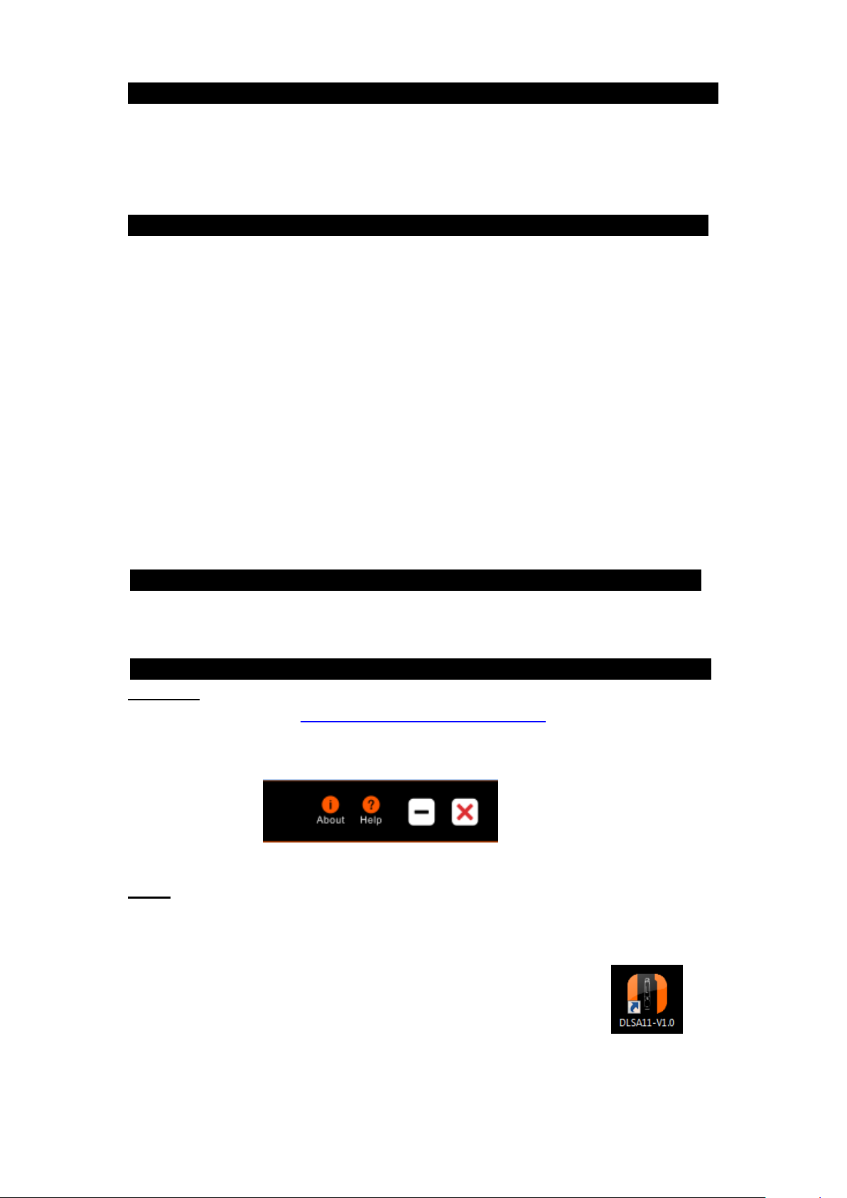
Data management software can be downloaded from the software platform by clicking the
help button.
Install the software first. Insert the data logger into the computer’s USB port and install the
drive software according to the prompt information. Open the software; the data logger will
automatically upload information after connecting to the computer. View information and
exit the interface.
Note that the software installation has added an icon to your desktop.
To access to the program, double-click on the icon.
R3-081016 2
Page 3

Default Settings
Other settings
Logging interval
5 minutes
0-11 hours; 0-59 minutes; 0-50 seconds
Stop mode:
Software
Manual stop (see pp. 3-4 )
Start Mode:
Instant on
Manual and timing start (pg. 3)
Temp. Unit
oC oF
Buffer Ring:
Disabled
Enabled
Alarm
Settings
H1 (high alarm) =
10 oC
User defined
L1 (low alarm) =
2 oC
Alarm Mode:
Single
Cumulative
Caution!
Make sure you have saved selected parameters.
Configure parameters
Refer to the data management software instructions for details (pages 8 –14)
Start the data logger
There are three modes to start the logger – instant-on, manual start, and timing start.
1. Instant-on: After parameter configuration, the data logger starts recording
immediately when it is disconnected from the USB.
2. Manual start: After parameter configuration, press and hold the button for 5
seconds to start the data logger. In this mode, it has a start delay function. If this
function is enabled, the data logger will not record data immediately after start-up
but start recording after the set delay time elapses.
3. Timing start: After parameter configuration and disconnection from USB, the data
logger starts recording when it reaches the set time.
View data instantly
If you need to view simple statistical information, you may directly press the button to turn
the page and check. The LCD screen can display MKT, average value, Max value and Min
value. Mean Kinetic Temperature (MKT) is a simplified way of expressing the overall effect
of temperature fluctuations during storage or shipment of perishable goods.
If you need detailed information, please connect the data logger to the computer’s USB.
After about 3 minutes, the data will be saved. You can open it as an Excel, AI or PDF
report.
Moreover, you can connect the data logger to a computer and analyze the data using the
data management software.
Stop the data logger
There are several modes to stop it – manual stop, stop via software, over-Maxrecord-capacity stop (enable/disable manual stop).
1. Manual stop: When the data logger is recording in this mode, you may press and hold
the button for 5 seconds to stop it.
2. Stop via software: You can stop the data logger via software
selecting the Stop recording option on the software platform.
If the record capacity reaches the Max value (32,000 points)
by
R3-081016 3
Page 4
and the data logger is not stopped manually, the data logger will save the data by
overwriting the initial data. (It keeps the statistical information of the whole
transportation process.)
NOTE: When the record capacity exceeds the Max capacity (32,000 points) in the
manual mode, the data logger can continue recording the temperature state of the
whole transportation process but only keep the details of the last 32,000 points.
Please use the ―manual stop‖ mode with caution if you have a need to trace back
the details of the whole process.
3. Over-Max-record-capacity stop (enable manual stop): In this mode, you can stop the
data logger by hand or via software, or it will stop automatically when the record data
reaches the Max capacity (32,000 points).
Over-Max-record-capacity stop (disable manual stop): In this mode, it will stop
automatically when the record data reaches the Max capacity (32,000 points), or
you can stop it via software.
View data
Connect the data logger to the computer via USB and then view the data.
View report via the data management software: Open the software and import the data as
Excel, Adobe Illustrator Artwork (AI) or PDF report. The software will display the
configuration information and recorded data.
Display menu instructions
Different screens are displayed when the unit is running. Below are various modes of
operation of the data logger.
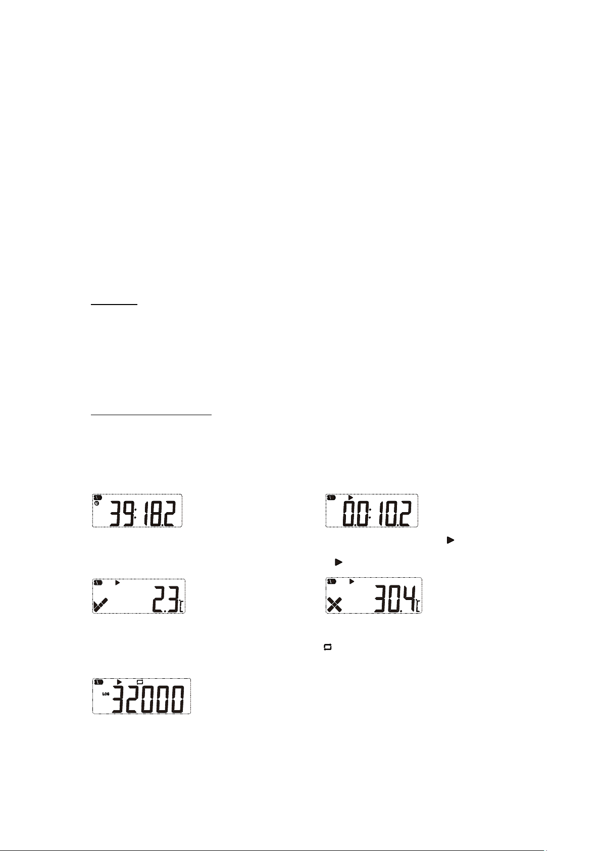
Menu 1: Start delay time or the remaining time of timing start (Hr: Min. Sec). See Figures
1 and 2. (This page is displayed only in start delay or timing start status.)
Fig.1: Start delay time Fig.2: Timing start delay ( flashing)
Menu 2: Current temperature. See Fig. 3, 4 (Static indicates it is recording.)
Fig.3 Current temperature (No alarm occurred) Fig.4 Current temperature (Alarmed)
Menu 3: Current record points. See Fig.5 (Static indicates the current record points
exceed the Max capacity and the data logger is overwriting initial data.)
Fig.5 Current record points
R3-081016 4
Page 5
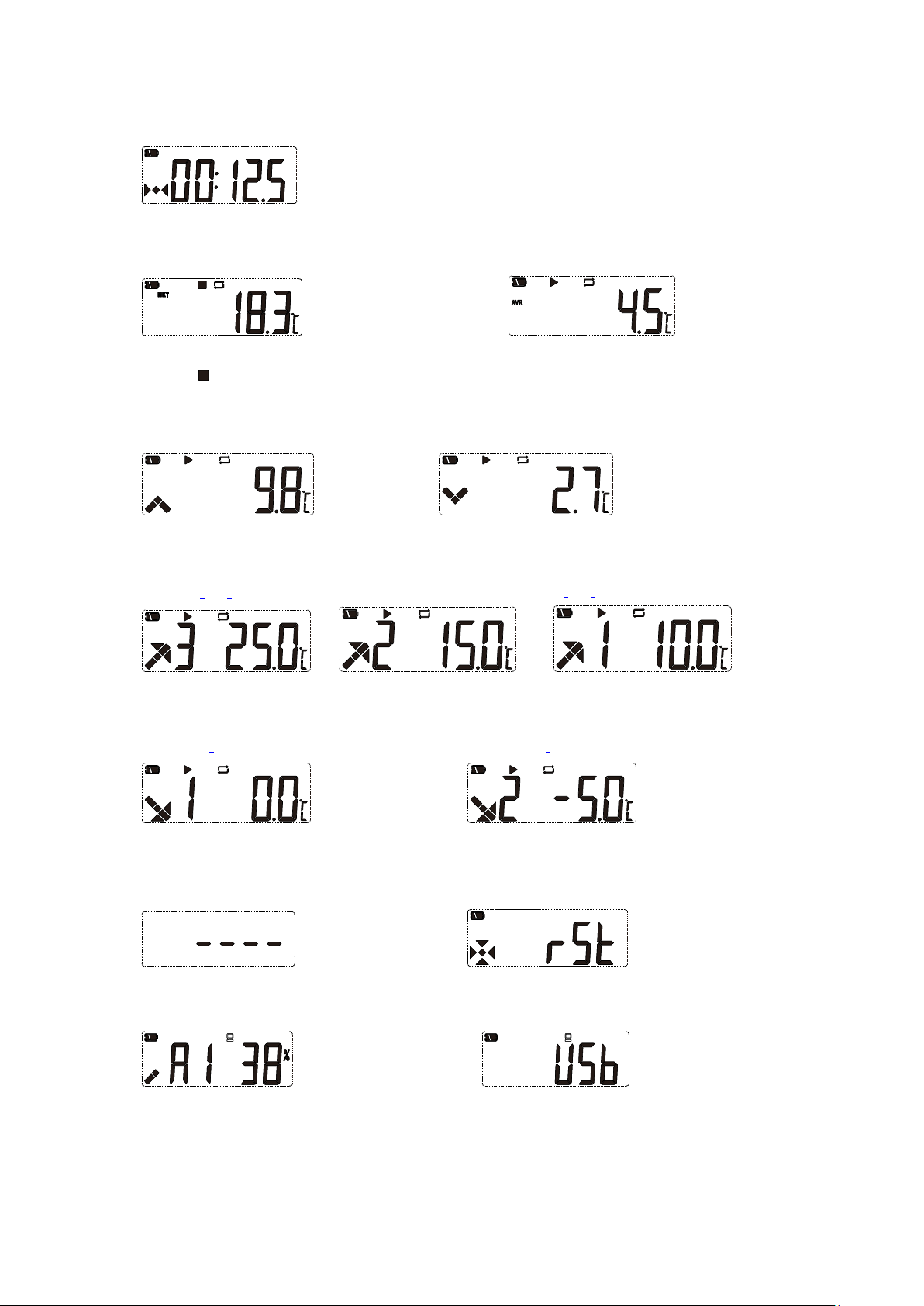
Menu 4: Current record interval. (e.g., the digit N following the decimal point represents
N*10 sec. Fig.6 shows the record interval is set to 12 min 50 sec.)
Fig.6 Record interval
Menu 5: MKT value. Menu 6: Average temperature value.
Fig.7 Fig.8
Static indicates it stopped recording
Menu 7: Max temperature value. Menu 8: Min temperature value.
Fig.9 Fig.10
Menu 9, 10, 11: Set upper limit of temperature. See Fig.11, 12, 13
Fig.11 Upper limit 3 Fig.12 Upper limit 2 Fig.13 Upper limit 1
Menu 12, 13: Set lower limit of temperature. See Fig.14, 15
Fig.14 Lower limit 1 Fig.15 Lower limit 2
Other status:
Fig.16 Deleting data Fig.17 Recovering data (Power on)
Fig.18 Generating report Fig.19 USB connection
R3-081016 5
Page 6

PLEASE NOTE
Before replacing the battery you must first shut down the data
logger. If not, when restarting the logger, the time will be incorrect.
1
USB
4 Transparent cap
2
LCD screen
5
Battery compartment
3
Button
Content of exported report
The report varies based on the set alarm types.
When unit is set to ―no alarm‖, there is no alarm info on the top right corner of the first
page or color mark among data.
When it is set to ―alarm‖, relative alarm info appears in the alarm info column based on the
selected alarms. Over high temperature data is in red. Below low temperature data is in
blue. Normal data is in black. If alarm cases occur, they will be marked as alarm status on
top right corner of the first page; otherwise, it is in normal status.
Finish viewing
Exit the data logger after viewing the report.
Product diagram……………………………………………………………………
Replacing the battery……………………………………………………………….
Step 1. Rotate the transparent cap and remove it in the direction shown in Fig. 20.
Fig.20
R3-081016 6
Page 7

Step 2. Press the snap to remove the compartment. See Fig. 21.
Fig.21
Step 3. Remove the battery compartment. See Fig. 22.
Fig.22
Step 4. Remove the old battery and Install the new one. See Fig. 23.
Fig.23
Step 5. Adjust the button and the internal light pipe to the same side; snap the
compartment shut. See Fig. 24.
Fig.24
Step 6. To re-install the transparent cap, rotate it in the direction shown in Fig. 25.
Fig.25
R3-081016 7
Page 8

Hardware environment:
Operation system:
CPU:above PII600MHZ
Hard disk:above 40G
Memory:above 512M
Windows XP(32bit、64bit, Windows Vista(32bit、
64bit, Win7(32bit、64bit), Windows8(x86/x64)
Tool buttons:
Function
Download recording data from logger
Database query interface
displays all saved data
information
Manually save data: if current data is not saved
into database, then press this button to save
data. For first time recording data, the system will
automatically save the data and display the prompt of auto data
saving. If new data is recorded and logger is inserted into
computer once more, user needs to save the data manually by
clicking the button, and it will display a dialog box to save the
data.
Export data in the format of AI,
EXCEL or ELT
Logger parameter setting
Data Management Software Instructions
Data Management Software can upload all recorded data to a computer and
systematically analyze, collect and manage data.
1. Installation environment
2. Main functions
2.1:Main interface
R3-081016 8
Page 9

Serial Number——Data logger ID
Stop Time——Stop time
Log Interval——Record interval
Data points——Total record points
Time Base——Time Zone
Elapsed time——Total record time
Start Mode——Logger start mode
MKT——Mean kinetic temperature
Start Delay——Logger start delay time
Over——Alarm upper limit
Buffer Ring——Buffer Ring
Below——Alarm lower limit
Trip ID——Trip ID number
Allow Time——Alarm delay time
Description—Trip description
Total time——Accumulated alarm time
Highest ——Max. Temperature
Violations——Times alarm occurs
Lowest ——Min. Temperature
Status ——Logger alarm status
Average ——Average Temperature
RH% - Relative Humidity
Stop Mode——Stop mode Set
Status ——Logger alarm status
Stop mode (actual)——Actual stop mode
T ---Temperature
Start Time——Start time
RH% - Relative Humidity
Multiple Work——Permits logger to be started or stopped several times
Function buttons
Stretches curve
horizontally
Contracts curve
horizontally
Zooms in
Zooms out
Returns curve to
original size
Parameter information:
Data Graph
R3-081016 9
Page 10

Data table
——Displays first page data
——Displays previous page data
——Displays next page data
——Displays last page data
——Skips to a specific page
R3-081016 10
Page 11

Selects all loggers
Views the detailed information of the selected logger
Deletes the data of selected logger
Displays all loggers that have exceeded upper/lower limit
Displays all recording (including normal temperature data
and over temperature data)
Data management function
Back to home page
3. Data query page
R3-081016 11
Page 12

4. Data management page
——Data backup (saves data in the format of ELT)
——Data restore (restores ELT file and reads it by software)
——Back to home page
5. Parameter setting page
R3-081016 12
Page 13

Parameter information:
Serial Number——Data logger ID
Start Mode——Logger start mode
Trip ID——Travel ID number
Travel DSC——Travel description
Log Interval——Record interval
Report Language——Report Language
Time Base——Time Base
Battery——Battery display
Cycle—— Total record time available
No Alarm ——Alarm threshold not set
Password——Setting password
Stop Mode——Logger stop modes
Multiple Alarm——Set several alarm thresholds
Multiple Work——Permit logger to be started or stopped several times
Probe Type——Temperature sensor type (internal or external)
Start time——Logger starts automatically at set time
Saves
parameters
Saves
parameter
setting
Loads parameter
setting
Back to home page
Sensor
adjustment
6. Sensor Adjustment
R3-081016 13
Page 14

Export data in the
EXCEL format
Export data in the
AI format
Export data in the
ELT format
Restore/insert
ELT data to the
software
accucoldloggers.com
Phone: 718-893-3900
Fax: 844-478-8799
Accucold, Felix Storch, Inc., Summit Appliance Division | 770 Garrison Avenue | Bronx, NY 10474
7. Export data page
Customer Support …………………………………………………………….………
For technical support, please call 800-932-4267 (U.S. and Canada) or email
info@summitappliance.com; for calibration services please contact calibration@summitappliance.com .
Limited Warranty…………………………………………………………….………
Within the 48 contiguous United States, for 90 days from the date of purchase, when this
appliance is operated and maintained according to instructions furnished with the product,
warrantor will pay for factory-specified parts and repair labor to correct defects in materials
or workmanship. Service must be provided by a designated service company. Outside the
48 states, all parts are warranted for 90 days from manufacturing defects. Plastic parts are
warranted to be manufactured to commercially acceptable standards, and are not covered
from damage during handling or breakage. Warrantor will not pay for damage resulting
from accident, alteration, misuse, abuse, fire, flood, acts of God, improper installation,
installation not in accordance with electrical codes, or use or modifications of products not
approved by warrantor.
R3-081016 14
 Loading...