

Summit 2196 model, 2196-LF model, 2196-R model, 2796 model Installation, Operation And Maintenance Manual
Page 1

SUMMIT PUMP
Model 2196 / 2196-LF / 2196-R / 2796
ANSI Standard Process Pump Family
Installation, Operation, and Maintenance Manual
Rev. 7/2003
Page 2

Page 3

WARRANTY
Pumping units assembled by Summit Pump, Inc., Green Bay, WI are guaranteed to be
free from defects in material and workmanship for one year from date of shipment from
factory in Green Bay, WI. The obligation under this Warranty, statutory or otherwise, is
limited to replacement or repair at Green Bay, WI, of such part as shall appear to us upon
inspection at such point, to have been defective in material or workmanship.
This Warranty does not obligate Summit Pump, Inc. to bear the cost of labor or
transportation charges in connection with replacement or repair of defective parts; nor
shall it apply to a pump upon which repairs or alterations have been made unless
authorized by Summit Pump, Inc.
No warranty is made in respect to engines, motors, or trade accessories, such being
subject to warranties of their respective manufacturers.
No express implied or statutory warranty, other than herein set forth is made or
authorized to be made by Summit Pump, Inc.
In no event shall Summit Pump, Inc. be liable for consequential damages or contingent
liabilities arising out of the failure of any Summit Pump, Inc. pump or parts thereof to
operate properly.
SUMMIT PUMP, INC.
Green Bay, WI
LIABILITY
Summit Pump, Inc. shall not be liable for personal physical injury, damage or delays
caused by failure to follow the instructions and procedures for installation, operation and
maintenance contained in this manual.
COPYRIGHT
This Installation, Operation, and Maintenance Manual contains proprietary information,
which is protected by copyright. No part of this Installation, Operation, and Maintenance
Manual may be photocopied or reproduced without prior written consent from Summit
Pump.
The information contained herein is for informational use only and is subject to change
without notice. Summit Pump assumes no responsibility or liability for any errors or
inaccuracies that may appear in this manual.
© 2003 by Summit Pump. All rights reserved.
Page 4

Page 5

Installation, Operation, and Maintenance Manual
Contents
1. INTRODUCTION 1
SAFETY 1
2196 MODEL RELATIONSHIP CHART 2
2. RECEIPT AND STORAGE 3
RECEIVING THE PUMP 3
STORING THE PUMP 3
3. INSTALLATION 4
LOCATION 4
FOUNDATION 4
PIPING CONNECTION – SUCTION / DISCHARGE 4
ALIGNMENT 5
STUFFING BOX 5
Packed Box 5
Cartridge Mechanical Seal 6
Type 1 Mechanical Seal 6
4. OPERATION 8
LUBRICATION 8
Oil Lubrication 8
Grease Lubrication 8
ROTATION 9
IMPELLER CLEARANCE 10
PRIMING 10
START UP 10
SHUT DOWN 11
APPENDIX A - IMPELLER CLEARANCE SETTING 12
FEELER GAUGE TECHNIQUE 12
Models 2196, 2196-LF and 2796 12
Model 2196R Feeler Gauge Technique 13
DIAL INDICATOR TECHNIQUE 14
Models 2196, 2196-LF and 2796 14
Model 2196-R Dial Indicator Technique 15
APPENDIX B - CENTRIFUGAL PUMP TROUBLESHOOTING 16
APPENDIX C - MAINTENANCE AND REPAIR 18
DISASSEMBLY PROCEDURES 18
ASSEMBLY PROCEDURES 20
APPENDIX D – PUMP CROSS SECTIONS AND PARTS LISTS 24
MODEL 2196 STO CROSS SECTION 24
MODEL 2196 STO PARTS LIST 24
MODEL 2196 MTO CROSS SECTION 25
MODEL 2196 MTO PARTS LIST 25
MODEL 2196 LTO CROSS SECTION 26
MODEL 2196 LTO PARTS LIST 26
MODEL 2196 XLO CROSS SECTION 27
SUMMIT PUMP MODEL 2196 / 2196-LF / 2196-R / 2796 i
Page 6

Installation, Operation, and Maintenance Manual
MODEL 2196 XLO PARTS LIST 27
MODEL 2196-LF CROSS SECTION 28
MODEL 2196-LF PARTS LIST 28
MODEL 2196-R CROSS SECTION 29
MODEL 2196-R PARTS LIST 29
MODEL 2796 CROSS SECTION 30
APPENDIX E – MAINTENANCE INSTRUCTIONS FOR INPRO/SEAL®
“VBX” BEARING ISOLATORS 32
DETAILS OF OPERATIONS 32
DISASSEMBLY PROCEDURES 32
INSTALLATION PROCEDURES 33
APPENDIX F – DIMENSIONAL DATA 34
MODEL 2196 DIMENSIONAL DATA 34
MODEL 2196 BASEPLATE RELATED DIMENSIONS 35
MODEL 2196-LF DIMENSIONAL DATA 36
MODEL 2196-R DIMENSIONAL DATA 37
MODEL 2796 DIMENSIONAL DATA 38
MODEL 2196 STUFFING BOX RELATED DIMENSIONS 39
APPENDIX G – CONSTRUCTION DETAILS 40
MODEL 2196 CONSTRUCTION DETAILS 40
APPENDIX H – ANSI B15.1 COUPLING GUARDS 41
INSTALLATION INSTRUCTIONS FOR SUMMIT PUMP ANSI B15.1 COUPLING
GUARDS 41
ASSEMBLY PROCEDURES 41
DISASSEMBLY PROCEDURES 45
ii SUMMIT PUMP MODEL 2196 / 2196-LF / 2196-R / 2796
Page 7

Installation, Operation, and Maintenance Manual
1. INTRODUCTION
This installation, operation, and maintenance manual is designed to help you achieve
the best performance and longest life from your Summit Pump models 2196, 2196LF, 2196-R, and 2796.
This pump is an open impeller, centrifugal model with end suction / top discharge.
The pump is designed for handling mild industrial corrosives.
If there are any questions regarding the pump or its application, which are not
covered in this manual or in other literature accompanying this unit, please contact
your Summit Pump distributor.
For information or technical assistance on the power source, contact the power source
manufacturer’s local dealer or representative.
SAFETY
The following message types are used in this manual to alert maintenance personnel
to procedures that require special attention for the protection and safety of both
equipment and personnel:
WARNING!
Failure to comply with the warnings in this
manual could result in personal injury or
death.
CAUTION!
Failure to comply with the cautions in this
manual could result in destruction of or
damage to equipment.
NOTE: Identifies a condition or
procedure which is essential to
proper equipment operation.
SUMMIT PUMP MODEL 2196 / 2196-LF / 2196-R / 2796 1
Page 8
Installation, Operation, and Maintenance Manual
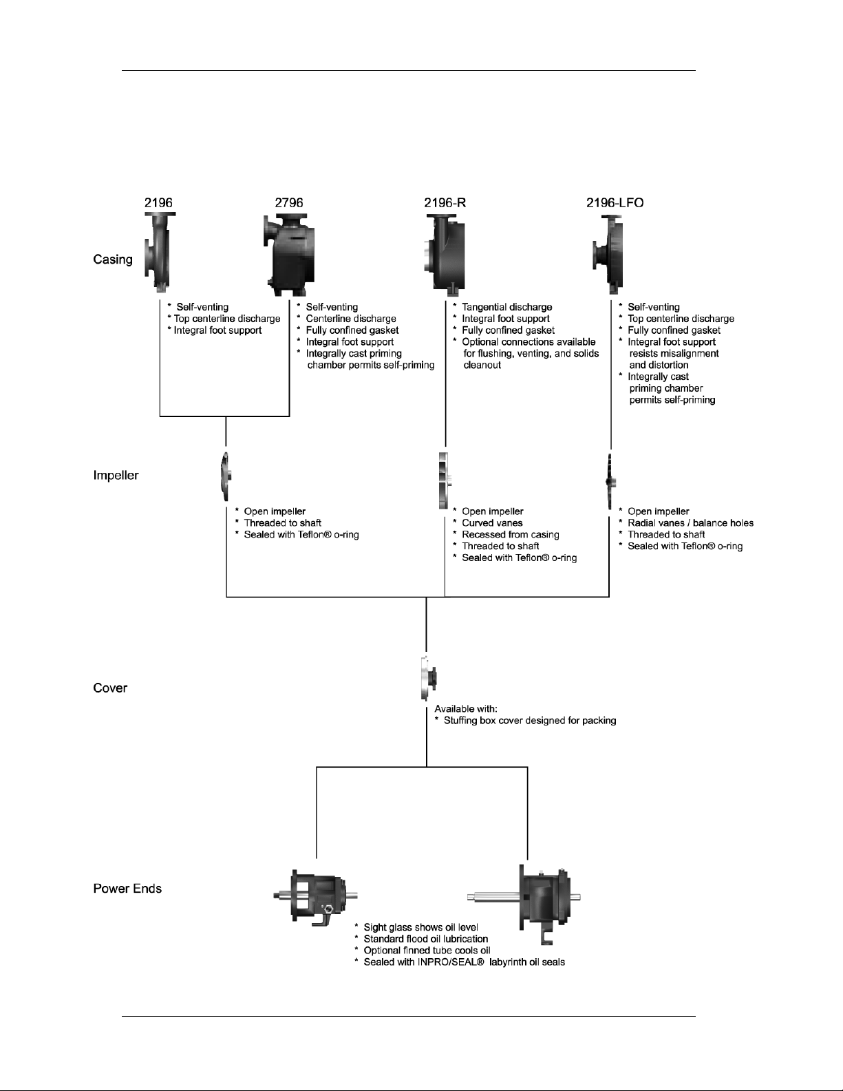
2196 MODEL RELATIONSHIP CHART
The following chart shows the relationship and parts commonality within the 2196
ANSI family model lines.
2 SUMMIT PUMP MODEL 2196 / 2196-LF / 2196-R / 2796
Page 9

Installation, Operation, and Maintenance Manual
2. RECEIPT AND STORAGE
RECEIVING THE PUMP
WARNING!
Failure to properly lift and move pump
could result in serious personal injury.
Immediately upon arrival, carefully inspect the pump for evidence of damage
during transit. Immediately report any damage to your Summit Pump Distributor.
STORING THE PUMP
Store the pump in a clean dry place. Do not remove piping connection covers.
Rotate the pump shaft by hand at least once per week to maintain a protective
film of oil or grease on the bearings. If you anticipate long-term storage, special
treatment is available for purchase from Summit Pump, Inc.
SUMMIT PUMP MODEL 2196 / 2196-LF / 2196-R / 2796 3
Page 10

Installation, Operation, and Maintenance Manual
3. INSTALLATION
LOCATION
When choosing a location for the pump, select an area that provides easy access
for inspection and maintenance. Locate the pump as close as possible to the
source which will provide NPSH (Net Positive Suction Head) equal to or greater
than that required by the pump at any capacity over its expected operating range.
FOUNDATION
Use a foundation that is sufficient enough to support all points of the pump baseplate. Level and grout the base-plate per standard construction practices (see
ANSI/HI 1.4.2-1997).
PIPING CONNECTION – SUCTION / DISCHARGE
All piping must be independently supported and accurately aligned to the pump
suction and discharge flanges. Ideally, you should place a short length of flexible
or bellows type spool piece in the connections directly next to the pump flange.
WARNING!
Lock out driver power before beginning to
work on pump.
CAUTION!
Never use force to align piping to the
pump flanges.
CAUTION!
Never operate pump with suction valve
closed.
At a minimum, use suction pipe that is one size larger than the flange. Use an
eccentric reducer to meet the suction pipe with the pump. Mount the reducer flat
side up. Elbows must be a minimum of ten diameters from the suction flange.
CAUTION!
Never operate pump with discharge valve
closed.
The discharge piping should include isolation and check valves. The check valve
prevents the pump from rotating backward. Place the check valve between the
4 SUMMIT PUMP MODEL 2196 / 2196-LF / 2196-R / 2796
Page 11

Installation, Operation, and Maintenance Manual
pump and isolation valve. The isolation valve is used for priming, starting, and
shutting down the system. If you use pipe diameter increasers, place them
between the pump and the check valve.
ALIGNMENT
The alignment at the pump and drive shaft is one of the most important
considerations in the pump installation.
WARNING!
Lock out pump driver. Failure to do so
could result in serious personal injury.
TO ALIGN THE PUMP
1. Use flexible spacer couplings to achieve proper alignment.
2. Check and adjust the parallel and angular alignment to within .005 inches
prior to connecting the coupling halves.
3. Jog the motor to check rotation. Its arrow should match up with the arrow on
the pump.
4. Install a coupling guard when the pump is aligned.
Pumps in hot service will need an alignment check at operating temperatures.
STUFFING BOX
Packed Box
Braided packing is supplied as standard equipment on all pumps. Install gland
bolt nuts finger-tight only. Adjust the gland bolt nuts during start-up to achieve
40-65 drops of leakage per minute. Specific packing type is dependent on pH,
temperature, etc. of the liquid being pumped.
Table 1
Pump Model
STO MTO LTO XLO
Packing Size 7/16 5/8
Number of Rings 5
Clean and cool pumpage may be used to lubricate the packing. If the pumpage is
not suitable, you must supply an external source of lubrication.
SUMMIT PUMP MODEL 2196 / 2196-LF / 2196-R / 2796 5
Page 12

Installation, Operation, and Maintenance Manual
CAUTION!
Do not allow packing to run dry. It must
be lubricated.
See ANSI/ASME B73.1 M-1984 for
proper seal flush plans.
Cartridge Mechanical Seal
WARNING!
Determine the effects that a failure of the
mechanical seal might have on the
environment and personnel and correct
conditions to prevent personal injury.
WARNING!
Only work on seal when the pump is
locked out and the seal is depressurized.
Refer to the Burgmann installation, operating, and maintenance instructions.
Failure to do so can result in environmental damage, personal injury, and seal
malfunction and / or seal failure. Pay particular attention to paragraphs 4.2, 4.3
and 4.4.
Start Up
Read, understand and follow the Burgmann Operation section 4.0, paragraphs 4.1
and 4.2
Storage, Assembly and Disassembly
Refer to the Burgmann Seal Storage assembly and disassembly sections 3.0, 3.1,
3.2, and 3.3, paying particular attention to the seal drawing included in the
instructions.
Type 1 Mechanical Seal
TO INSTALL TYPE 1 MECHANICAL SEAL
1. MTO, LTO, XLO Slide the stuffing box cover over the shaft/sleeve. Bolt the
cover (184) to the frame adapter(108).
STO Slide the 6” or 8” stuffing box cover (184) with adapter ring (108) over
shaft and bolt to bearing.
2. Mark / scribe the shaft at the face of the stuffing box.
3. Unbolt and remove the stuffing box cover.
6 SUMMIT PUMP MODEL 2196 / 2196-LF / 2196-R / 2796
Page 13

Installation, Operation, and Maintenance Manual
4. Locate the installation reference dimension on the seal installation drawing.
Normally this is the dimension from the face of the stuffing box to the rear of
the seal.
5. Mark the shaft with a felt marker or marking tool at the dimension (i.e. 1/32”).
6. Lubricate the shaft with silicon grease or soapy water. Slide the seal onto the
shaft. Line up the face of the seal with your mark and secure with set screw.
7. Reassemble the pump.
SUMMIT PUMP MODEL 2196 / 2196-LF / 2196-R / 2796 7
Page 14

Installation, Operation, and Maintenance Manual
4. OPERATION
LUBRICATION
CAUTION!
PUMPS ARE SHIPPED WITH NO OIL IN
THE BEARING FRAME! Oil must be
installed before operating the pump.
Ball bearings are very sensitive to both over and under lubrication, both being
detrimental to bearing performance. Either case is detrimental to bearing
performance. Use a thermometer to determine overheating. Excessive overheating
will reduce bearing life.
The relationship between temperature and pumpage temperature is an indication of
performance. Table 2 indicates the relationship between these temperatures.
Table 2
Degrees Fahrenheit
Pumping liquid temperature
Approximate normal line bearing temperature
60° 200° 300°
115° 140° 160°
The information shown in Table 2 is based on a room temperature of 70°F. Maximum
bearing temperature is 175°F. The temperatures shown above have a tolerance of plus
15°F. It is necessary to flush water on the shaft for liquid temperatures above 250°F.
This can be done either through a flushing gland or the stuffing box seal cage.
Oil Lubrication
Use only high quality turbine oil with rust and oxidation inhibitors. Service
temperatures determine oil viscosity. See Table 3.
Use a 300 SSU viscosity at 100° F for applications where pumping temperatures are
below 200° F. At pumping temperatures above 350° F, use 470 SSU at 100° F with
optional cooler.
Table 3
Bearing Temperature ISO Grade Viscosity at 100 Degrees F
Up to 150° F
150° F to 200° F
46 215 SSU
68 300 SSU
Above 200° F
100 470 SSU
Grease Lubrication
Regrease grease lubricated bearings with NLG1 No. 2 consistency grease for
8 SUMMIT PUMP MODEL 2196 / 2196-LF / 2196-R / 2796
Page 15

Installation, Operation, and Maintenance Manual
pumpage temperatures -60° F to 350° F. Grease is not recommended for temperatures
above 350° F. Regrease bearings every three months.
Table 4
Acceptable Lubricating Oils
ISO VG 32 46 68 100
Keystone: KLC Antiwear 32 46 68 100
Lubriplate AC0 AC1 AC2 AC3
Mobil: DTE Light - Medium Heavy
Mobil: Synthetic 624 525 626 627
Phillips: Magnus 32 46 68 100
Synthetic, syndustrial mist 100
Shell: Tellus Fluids HD 32 46 68 100
Table 5
Acceptable Greases
Citgo Mystic EP2
Keystone 81EP2
Mobil Mobilux EP2
Mobil Synthetic SCH 100
TO REGREASE LUBRICATED BEARINGS
1. Wipe dirt and foreign matter from the fittings.
2. Remove grease relief plugs from the bottom of the frame.
3. Fill grease through fittings until it comes out through the relief holes.
4. Reinstall grease relief plugs.
ROTATION
TO ROTATE THE PUMP
1. Lock out power to the pump driver.
2. Remove the coupling guard and coupling.
3. Momentarily restore power and energize the motor to determine rotation.
4. Confirm that motor rotation coincides with proper pump rotation. The proper
pump rotation is counterclockwise when facing the pump’s suction. Lock out
power to pump driver.
WARNING!
Operating the pump in the opposite
rotation may dislodge the impeller
SUMMIT PUMP MODEL 2196 / 2196-LF / 2196-R / 2796 9
Page 16

Installation, Operation, and Maintenance Manual
causing severe damage to the impeller
and/or casing.
5. Reinstall the coupling and coupling guard.
6. Unlock power to pump driver.
IMPELLER CLEARANCE
WARNING!
Check impeller clearance prior to starting
pump. Setting may have changed during
transit.
WARNING!
Lock out power prior to working on pump.
Impeller clearance is the measurement between the impeller vanes and the surface of
the casing. This clearance is set at .015 inches during assembly, but may need to be
adjusted before initial startup. (See APPENDIX A for detailed procedures on setting
the impeller clearance.)
PRIMING
Prior to starting a centrifugal pump, it is imperative that you prime the pump by
flooding the suction piping and casing with fluid. Priming will occur when you open
the suction isolation valve and the packing sealing liquid valve.
CAUTION!
Do not operate the pump without liquid in
the casing.
START UP
TO START UP THE PUMP
1. Rotate the pump by hand; making sure that the rotating element is spinning freely.
2. Be sure the suction valve is open.
3. Partially close the discharge valve.
CAUTION!
Do not operate the pump with the
discharge valve closed for an extended
period of time.
10 SUMMIT PUMP MODEL 2196 / 2196-LF / 2196-R / 2796
Page 17

Installation, Operation, and Maintenance Manual
4. Unlock power to the pump driver.
5. Slowly open the discharge valve as soon as the motor reaches operating speed.
6. Check stuffing box leakage and adjust, if necessary, to achieve leakage of 40-65
drops per minute.
7. Adjust the discharge valve as needed while checking piping for leaks.
8. Check mechanical operation of the pump and motor.
WARNING!
Do not operate the pump without the
proper guard. See ANSI/ASME
B15.1-1996.
SHUT DOWN
TO SHUT DOWN THE PUMP
1. Gradually close the discharge valve and turn off the power to the motor.
2. Lock out power to the pump driver.
SUMMIT PUMP MODEL 2196 / 2196-LF / 2196-R / 2796 11
Page 18

Installation, Operation, and Maintenance Manual
APPENDIX A - IMPELLER CLEARANCE SETTING
A gradual loss in head and/or capacity can occur. You may restore performance by
adjusting the impeller clearance, which is the measurement between the impeller
vanes and the surface of the casing.
Table 6
Temperature Impeller Clearance
200° F (93°C)
250° F (121°C)
300° F (144°C)
350° F (177°C)
400° F (204°C)
.015” (.38 mm)
.017” (.43 mm)
.019” (.48 mm)
.021” (.53 mm)
.023” (.58 mm)
FEELER GAUGE TECHNIQUE
Models 2196, 2196-LF and 2796
TO USE THE FEELER GAUGE TECHNIQUE FOR IMPELLER CLEARANCE SETTING
FOR MODELS 2196, 2196-LF & 2796
1. Lock out power to the pump driver.
2. Remove the coupling guard.
3. Loosen jacking bolts (370D) and jam nuts (423).
4. Tighten bearing housing bolts (370C) evenly, while slowly rotating the shaft until
the impeller starts to rub on the casing.
5. Using a feeler gauge, set the gap between the 3 housing bolts (370C) and the
bearing housing (134). (Refer to Table 6 for settings.)
6. Tighten jack bolts (370D) evenly until bearing housing backs out and contacts the
bearing housing bolts (370C).
7. Tighten jam nuts (423) evenly, rotating the shaft to make sure the assembly turns
freely.
8. Reinstall the coupling guard.
9. Unlock power to the pump driver.
12 SUMMIT PUMP MODEL 2196 / 2196-LF / 2196-R / 2796
Page 19

Installation, Operation, and Maintenance Manual
Model 2196R Feeler Gauge Technique
TO USE THE FEELER GAUGE TECHNIQUE FOR IMPELLER CLEARANCE SETTING
FOR MODEL 2196-R
1. Lock out power to the pump driver.
2. Remove the coupling guard.
3. Remove coupling.
4. Loosen bearing housing bolts (370C) several turns.
5. Loosen jam nuts (423) and turn jackbolts (370D) evenly around several turns until
impeller contacts stuffing box cover (184). Turn shaft to ensure contact is
complete.
6. Use feeler gauge to measure the gap between the bearing frame (228) and the
bearing housing (134). Reduce the measurement by .060” and place the resulting
feeler gauge thickness between the bearing housing (134) and the bearing frame
(228).
7. Loosen the jacking bolts (370D) several turns. Tighten the locking bolts (370C) to
move the impeller away from the stuffing box cover (184) until the bearing
housing (134) snugs up the feeler gauge between the bearing housing (184) and
the bearing frame (228).
8. Turn jacking bolts (370D) in and tighten jam nuts (423) evenly, rotating the shaft
to make sure the assembly turns freely.
9. Reinstall the drive coupling.
10. Reinstall the coupling guard.
11. Unlock power to the pump driver.
SUMMIT PUMP MODEL 2196 / 2196-LF / 2196-R / 2796 13
Page 20

Installation, Operation, and Maintenance Manual
DIAL INDICATOR TECHNIQUE
Models 2196, 2196-LF and 2796
TO USE THE DIAL INDICATOR TECHNIQUE FOR IMPELLER CLEARANCE SETTING
1. Lock out power to the pump driver.
2. Remove the coupling guard.
3. Place a dial indicator with a magnetic base on the pump base plate. Place the
indicator against the end of the pump shaft or coupling face.
4. Loosen jack bolts (370D) and jam nuts (423).
5. Tighten bearing housing bolts (370C) evenly while slowly rotating the shaft until
the impeller starts to rub on the casing.
6. Set the dial indicator to zero.
7. Tighten the jack bolts (370D) evenly until they contact the frame. Continue to
tighten until the dial indicator reads the proper clearance as shown in Table 6.
8. Tighten bearing housing bolts (370C) evenly; then tighten jack bolts (370D)
evenly. Be sure the dial indicator does not move from the proper setting.
9. Rotate the shaft to be sure it turns freely.
10. Reinstall the coupling guard.
11. Unlock power to the pump driver.
14 SUMMIT PUMP MODEL 2196 / 2196-LF / 2196-R / 2796
Page 21

Installation, Operation, and Maintenance Manual
Model 2196-R Dial Indicator Technique
1. Lock out power to the pump driver.
2. Remove the coupling guard.
3. Remove coupling.
4. Place a dial indicator with a magnetic base on the pump base plate. Place the
indicator tip in contact with either the shaft end or coupling face. (See diagram on
page14.)
5. Loosen bearing housing bolts (370C) several turns.
6. Loosen jam nuts (423) on jack bolts (370D) evenly around several turns until
impeller contacts the stuffing box cover (184). Turn the shaft to ensure contact is
made.
7. Set the dial indicator to zero.
8. Loosen the jacking bolts (370D) evenly several turns and tighten the bearing
housing bolts (370C) to move the impeller away from the stuffing box cover until
the dial indicator shows a 0.060” clearance.
9. Turn in the jacking bolts (370D) and tighten the jam nuts (423) evenly.
10. Rotate the shaft to be sure it turns freely.
11. Reinstall coupling.
12. Reinstall the coupling guard.
13. Unlock power to the pump driver.
SUMMIT PUMP MODEL 2196 / 2196-LF / 2196-R / 2796 15
Page 22

Installation, Operation, and Maintenance Manual
APPENDIX B - CENTRIFUGAL PUMP TROUBLESHOOTING
The following table provides possible solutions for symptoms that you may encounter
with your centrifugal pump.
WARNING!
Before attempting to service the pump:
1. Follow the shut down procedures.
2. Lock out the power source.
3. Allow the pump to cool.
4. Close the suction and discharge
valves.
5. Drain the pump.
Table 7
CENTRIFUGAL PUMP TROUBLESHOOTING
Symptom Cause Solution
Pump not
delivering liquid
Low flow and low
head
• Pump not primed. • Re-prime pump.
• Suction lift too high. • Install shorter suction pipe.
• Wrong direction of
rotation.
• Impeller clogged. • Back-flush pump.
• Suction line plugged. • Remove debris.
• Air leak in stuffing box. • Replace or adjust packing.
• Worn suction side plate. • Replace defective part.
• Impeller worn or
damaged.
• Air leak in suction line. • Replace gasket.
• Impeller clogged. • Back-flush pump.
• Wrong direction of
rotation.
• Change motor wiring.
• Inspect and replace impeller, if
needed.
• Change motor wiring.
16 SUMMIT PUMP MODEL 2196 / 2196-LF / 2196-R / 2796
Page 23

Installation, Operation, and Maintenance Manual
Table 7 (continued)
CENTRIFUGAL PUMP TROUBLESHOOTING
Symptom Cause Solution
Pump loses prime
Bearings are
running hot
Motor requires
excessive
amperage
Stuffing box is
leaking
excessively
• Pump not primed
correctly.
• Air leak in suction line. • Replace gasket or pipe plug.
• Lantern ring in wrong
location.
• Misalignment. • Realign drive coupling.
• Low or insufficient
lubricant.
• Stuffing box gland is too
tight.
• Total dynamic head is too
low.
• Rotary part rubbing
stationary part.
• Liquid is heavier than
specified.
• Stuffing box is incorrectly
packed.
• Shaft sleeve is scored or
worn.
• Re-prime pump.
• Repack moving lantern ring to
correctly align with flush hole.
• Check oil level and or grease.
• Readjust or replace packing.
• Install throttle or reduce impeller
diameter.
• Adjust part or replace parts.
• Check specific gravity of liquid.
• Repack stuffing box.
• Replace shaft sleeve as required.
• Wrong type of packing. • Install correct packing.
• Shaft is bent. • Replace shaft.
• Worn mechanical seal
parts.
• Rebuild seal; replace parts.
SUMMIT PUMP MODEL 2196 / 2196-LF / 2196-R / 2796 17
Page 24

Installation, Operation, and Maintenance Manual
APPENDIX C - MAINTENANCE AND REPAIR
WARNING!
WEAR EYE PROTECTION. Failure to do
so can result in serious personal injury.
DISASSEMBLY PROCEDURES
(See APPENDIX D for cross-section of corresponding model.)
TO DISASSEMBLE YOUR MODEL 2196, 2196-LF, OR 2196-R PUMP
1. Lock out power supply at the motor starter.
2. Close off discharge, suction, sealing fluid, and cooling fluid.
3. Drain casing and flush, if needed.
WARNING!
Pump parts are heavy. Use proper lifting
methods to avoid personal injury.
4. Place lifting sling through frame to ensure safe handling during disassembly/
assembly.
5. Remove bolts (370) holding the frame adapter (108) to casing (100).
6. Pull the frame adapter back from casing.
7. Take the frame assembly to bench and secure for further work.
8. Scribe the location of coupling half on the shaft (122) and remove the coupling.
WARNING!
Never use heat to remove impeller. Heat
combined with trapped fluid could cause
an explosion, which can result in personal
injury.
9. Remove the impeller (101) from the shaft (122) while holding the shaft with a
strap wrench or suitable tool that will not mark the shaft.
NOTE: Threads are right-handed.
18 SUMMIT PUMP MODEL 2196 / 2196-LF / 2196-R / 2796
Page 25

Installation, Operation, and Maintenance Manual
NOTE: XLO – Remove impeller plug
(428Y) from the impeller (101). Do not
save impeller gasket (428D).
For a packed pump:
a. Remove the packing gland nuts (353A).
b. Slide gland toward frame (228).
c. Remove seal chamber nuts (423B).
d. Slide off stuffing box cover (184).
e. Remove packing (106) and lantern ring (105).
For a mechanical seal:
a. Remove the seal gland nuts (353).
b. Remove seal gland nuts (353A).
c. Slide gland toward frame (228), exercising care so as to not drop stationary set
from gland.
d. Remove seal chamber nuts (423B).
e. Slide off stuffing box cover (184).
f. Remove mechanical seal rotating element (383) and sleeve (128) from pump
shaft.
g. Loosen set screws if present. Refer to cartridge seal manufacturer’s
instructions.
h. Slide off seal gland with stationary seal and o-ring gasket.
10. Remove the frame adapter (108) by removing two dowel pins (469B) and four
adapter bolts (370B) and then separate the adapter (108) from the bearing frame
(228).
NOTE: This step does not apply to the
6” STO Model.
11. Remove the bearing housing bolts (370C) and loosen the jam nuts (423).
12. Tighten the jack-bolts (370D) evenly to push the bearing housing out of frame.
13. Slide shaft assembly, with housing, out of bearing frame.
14. On the STO and MTO, remove the bearing housing snap ring (361A).
On the LTO
and XLO, remove bearing cover screws (370G) and remove bearing
cover (109C). Then remove the bearing housing (134) by tapping with a rubber
hammer.
SUMMIT PUMP MODEL 2196 / 2196-LF / 2196-R / 2796 19
Page 26

Installation, Operation, and Maintenance Manual
15. Remove bearing lock nut (136) and bearing lock washer (382).
16. Remove inboard bearing (168A) and outboard bearing (112). Use an arbor press
or bearing puller to facilitate. On LTO models only, do not remove oil ring
(248A) unless it is damaged.
NOTE: Do not use a hammer, which
may cause damage to the shaft.
17. Complete disassembly of bearing frame (228). Remove oil plug (408A) (not
shown), oil sight glass (145), oil cooler inlet (408L), outlet plugs (408M), and
frame foot attachment bolt (529) and foot (241), where applicable.
18. Inspect all parts for cracks, erosion, pitting, rusting, damaged threads, corrosion,
and groove worn shaft/sleeve. Replace casing if grooves and pits are greater than
1/8” deep. Replace impeller if grooves are greater than 1/16” or even wear
exceeds 1/32”. Inspect shaft sleeve if grooved or pitted. Shaft run out or bearing
shoulder damage is cause for replacement.
ASSEMBLY PROCEDURES
(See APPENDIX D for cross-section of corresponding model.)
TO ASSEMBLE YOUR PUMP
1. Clean the bearing frame and inspect all tapped holes. Chase as needed.
2. Install oil fill plug (113A), oil sight glass (144), and frame lubrication plugs
(408H).
3. Attach bearing frame foot (241) with bolts (529), where applicable.
4. On the LTO model, install oil ring (248A) on shaft (122), if removed. Oil ring is a
press fit onto shaft.
NOTE: Use proper size drive tool to
prevent damage.
5. On the LTO
6. Install outboard bearing (112) on shaft (122).
If grease lubricated, install with shield away from impeller end.
If oil lubricated
model, install bearing cover (109C) over shaft (122).
, there should be no seals or shields.
20 SUMMIT PUMP MODEL 2196 / 2196-LF / 2196-R / 2796
Page 27

Installation, Operation, and Maintenance Manual
The recommended bearing installation method is heating the bearing using an
induction heater.
WARNING!
WEAR INSULATED GLOVES when using
heater. Failure to do so can result in
serious personal injury while handling hot
bearings.
NOTE: LTO frames use duplex angular
contact bearings.
Make sure bearings are mounted
in the correct order, back to
back.
7. Install a bearing lock washer (382) on the shaft.
a. Place tang of lock washer in shaft keyway.
b. Install lock-nut (136) on shaft.
c. Using a spanner wrench, tighten the nut until snug; then bend any one of the
tangs into a lock-nut slot.
8. Install inboard bearing (168A) on shaft (122).
If grease lubricated, install with shield toward impeller end.
If oil lubricated, there should be no seals or shields.
9. Install the outboard labyrinth oil seal (332A) in the bearing housing (134). Follow
Maintenance instructions in Appendix E.
NOTE: Make sure drain slots face down.
10. Apply a thin coating of lubricant to the inside of the bearing housing (134).
11. Slide the bearing housing (134) over the outboard bearing assembly (112) and
shaft (122). Place the coupling end of the shaft into the bearing housing through
the labyrinth oil seal.
On the XLO model, install the bearing cover gasket (360G).
On the STO and MTO models, install the bearing housing snap ring (361A) into
the groove on the bore of the bearing housing. Make sure the flat side is toward
the bearing.
On the LTO
and XLO models, install bearing cover (109C) and bolts (370G).
12. Install a new O-ring (496) over the O.D. of the bearing housing.
13. Apply a thin coating of lubricant to the outside of the bearing housing (134) and
slide the assembly into the bearing frame (228).
SUMMIT PUMP MODEL 2196 / 2196-LF / 2196-R / 2796 21
Page 28

Installation, Operation, and Maintenance Manual
14. Install bearing housing bolts (370C) into bearing frame (228) and install jack bolts
(370D) and jam nuts (423). Hand-tighten evenly.
15. Attach frame (228) to adapter (108).
a. Align dowel pins (469B) and adapter bolt (370B).
b. Tighten using criss-cross pattern.
c. Rotate shaft 360 degrees. It should be free.
NOTE: These steps do not apply to the
6” STO Model.
16. Set frame (228) and adapter (108) upright. Clamp to bench for safety as assembly
continues.
17. Install inboard bearing labyrinth seal in adapter frame. Make sure that the seal’s
drain slots face down. Follow Maintenance instructions in Appendix E.
18. Put anti-seize compound on the shaft and, if equipped, install shaft sleeve (126)
onto shaft (122).
19. Align anti-rotation pin with notch in sleeve (126).
For mechanical seal pumps, read manufacturer’s instructions for assembly. (See
STUFFING BOX on page 5.)
20. Install stuffing box cover (184) onto adapter with studs (353) and nuts (353A).
21. Install impeller (101) with new O-ring (496A).
22. Using an impeller wrench or strap wrench on the coupling end of the shaft,
tighten by rotating clockwise. Make sure coupling is tight to the shaft.
23. For packed pumps, install the appropriate packing (106) in the stuffing box cover
(184) according to fluid being pumped (105).
a. First, insert two packing rings into bottom of box.
b. Next, insert the lantern ring (105). Make sure to stagger packing joints and
lantern ring joint by 90 and be sure lantern ring lines up with flushing
connection. Install gland halves (107).
c. Hand-tighten nuts (353A). You must make final adjustments after the pump
has begun operation.
For mechanical seal
pumps, continue by following manufacturer’s instructions
noted in Step 19.
24. Install casing gasket (351) onto stuffing box cover (184). At this point, the power
end is ready for reinstallation into the casing or for storage for future use.
25. If returning to service, slide assembly into casing (100).
26. Install casing bolts (370) into frame to pull assembly into casing.
27. Rotate the shaft to ensure that no rubbing exists.
22 SUMMIT PUMP MODEL 2196 / 2196-LF / 2196-R / 2796
Page 29

Installation, Operation, and Maintenance Manual
28. Adjust impeller clearance according to the instructions beginning on page 12.
29. Align drive coupling according to the instructions beginning on page 5, in
addition to coupling manufacturer instructions.
30. If the motor was replaced, check rotation prior to reconnecting coupling halves.
(See rotation instructions on page 9).
31. Reinstall coupling guard and return pump to service.
SUMMIT PUMP MODEL 2196 / 2196-LF / 2196-R / 2796 23
Page 30

Installation, Operation, and Maintenance Manual
APPENDIX D – PUMP CROSS SECTIONS AND PARTS LISTS
MODEL 2196 STO CROSS SECTION
MODEL 2196 STO PARTS LIST
Item # Qty Description Item # Qty Description
100 1 Casing 360Q 1 Gasket; Gland, Mech. Seal
101 1 Impeller 361A 1 Snap Ring, Bearing
105 1 Ring, Lantern 365 1 Seal, Mechanical Stationary Element
106 5 Packing 370 3 Bolt, Casing
107 1 Gland, Packing 370B** 4 Bolt, Frame / Adapter
108** 1 Adapter Ring 370C 3 Bolt, Bearing Housing
112 1 Bearing, Outboard 370D 3 Jack Bolt, Bearing Housing
113A 1 Plug, Oil Fill 370H 2 Stud, SBC / Adapter
122 1 Shaft 382 1 Lockwasher, Bearing
126 1 Sleeve, Shaft 383 1 Seal, Mechanical Rotating Element
134 1 Housing, Bearing 400 1 Key, Coupling
136 1 Locknut, Bearing 408A 1 Plug, Frame Lubrication Port
168A 1 Bearing, Inboard 408L 1 Plug, Oil Cooler Inlet (Not Shown)
184 1 Cover, Stuffing Box 408M 1 Plug, Oil Cooler OutIet (Not Shown)
228 1 Frame 412 1 O-ring, Impeller
250 1 Gland, Mechanical Seal 423 3 Jamnut, Bearing Housing / Frame
319 1 Sight Glass 423B 2 Nut, Box Cover/Adapter Stud
332A 1 Labyrinth, OB 496 1 O-ring,, Bearing Housing / Frame
333A 1 Labyrinth, IB 500 1 Pin, Sleeve
351 1 Gasket, Case
353 4 Stud, Gland
353A 4* Nut, Gland Stud * Packing Gland has only 2 Studs & Nuts
358A 1 Plug, Casing Drain ** Only Required on 8" Pump
24 SUMMIT PUMP MODEL 2196 / 2196-LF / 2196-R / 2796
Page 31

Installation, Operation, and Maintenance Manual
MODEL 2196 MTO CROSS SECTION
MODEL 2196 MTO PARTS LIST
Item # Qty Description Item # Qty Description
100 1 Casing 360D 1 Gasket, Frame/Adapter
101 1 Impeller 360Q 1 Gasket; Gland, Mech. Seal
105 1 Ring, Lantern 361A 1 Snap Ring, Bearing
106 5 Packing 365 1 Seal, Mechanical Stationary Element
107 1 Gland, Packing 370
108 1 Adapter 370B 4 Bolt, Frame / Adapter
112 1 Bearing, Outboard 370C 3 Bolt, Frame / Bearing Housing
113 1 Plug, Oil Fill 370D 3 Jack Bolt, Bearing Housing
122 1 Shaft 370F 2 Bolt, Frame Foot
126 1 Sleeve, Shaft 370H 2 Box Cover/Adapter Stud
134 1 Housing, Bearing 382 1 Lockwasher, Bearing
136 1 Locknut, Bearing 383 1 Seal, Mechanical Rotating Element
168 1 Bearing, Inboard 400 1 Key, Coupling
184 1 Cover, Stuffing Box 408A 1 Plug, Frame Drain (Not Shown)
228 1 Frame 408H 4 Plug, Frame Lubrication Port
241 1 Foot Frame 408L 1 Plug, Oil Cooler Inlet
250 1 Gland, Mechanical Seal 408M 1 Plug, Oil Cooler OutIet
319 1 Gauge; Sight, Oil 412 1 O-ring, Impeller
332A 1 Labyrinth, Outboard Frame 423 3 Jamnut, Bearing Housing Jack Bolt
333A 1 Labyrinth, Inboard Frame 423B 2 Nut, Box Cover/Adapter Stud
351 1 Gasket, Case 469B 2 Dowel Pin, Frame / Adapter
353 4 Stud, Gland 496 1 O-ring, Bearing Housing / Frame
353A 4* Nut, Gland Stud 529 2 Washer, Frame Foot to Frame
358A 1 Plug, Casing Drain * Packing Gland has only 2 Studs & Nuts
8, 12, 16
Bolt, Casing
SUMMIT PUMP MODEL 2196 / 2196-LF / 2196-R / 2796 25
Page 32

Installation, Operation, and Maintenance Manual
MODEL 2196 LTO CROSS SECTION
MODEL 2196 LTO PARTS LIST
Item # Qty Description Item # Qty Description
100 1 Casing 360D 1 Gasket, Frame/Adapter
101 1 Impeller 360Q 1 Gasket; Gland, Mech. Seal
105 1 Ring, Lantern 361A 1 Snap Ring, Bearing
106 5 Packing 365 1 Seal, Mechanical Stationary Element
107 1 Gland, Packing 370
108 1 Adapter 370B 4 Bolt, Frame / Adapter
109C 1 Cover; Bearing, Outboard 370C 3 Bolt, Bearing Housing
112 2 Bearing, Outboard 370D 3 Jack Bolt, Bearing Housing
113 1 Plug, Oil Fill 370F 2 Bolt, Frame Foot
122 1 Shaft 370G 6 Bolt, Bearing Cover
126 1 Sleeve, Shaft 370H 2 Box Cover/Adapter Stud
134 1 Housing, Bearing 382 1 Lockwasher, Bearing
136 1 Locknut, Bearing 383 1 Seal, Mechanical Rotating Element
168 1 Bearing, Inboard 400 1 Key, Coupling
184 1 Cover, Stuffing Box 408A 1 Plug, Frame Drain (Not Shown)
228 1 Frame 408H 4 Plug, Frame Lube Port (Not Shown)
241 1 Foot Frame 408L 1 Plug, Oil Cooler Inlet
248A 1 Ring, Oil 408M 1 Plug, Oil Cooler OutIet (Not Shown)
250 1 Gland, Mechanical Seal 412 1 O-ring, Impeller
319 1 Gauge; Sight, Oil 423 3 Jamnut, Bearing Housing Jack Bolt
332A 1 Labyrinth, Outboard Frame 423B 2 Nut, Box Cover/Adapter Stud
333A 1 Labyrinth, Inboard Frame 469B 2 Dowel Pin, Frame / Adapter
351 1 Gasket, Case 496 1 O-ring, Bearing Housing / Frame
353 4 Stud, Gland 500 1 Pin, Sleeve
353A 4* Nut, Gland Stud 529 2 Washer, Frame Foot to Frame
358A 1 Plug, Casing Drain * Packing Gland has only 2 Studs & Nuts
8, 12, 16
Bolt, Casing
26 SUMMIT PUMP MODEL 2196 / 2196-LF / 2196-R / 2796
Page 33

Installation, Operation, and Maintenance Manual
MODEL 2196 XLO CROSS SECTION
MODEL 2196 XLO PARTS LIST
Item # Qty Description Item # Qty Description
100 1 Casing 360 1 Gasket, End Cover
101 1 Impeller 360D 1 Gasket, Frame/Adapter
105 1 Ring, Lantern 370 16/24
106 5
107 1 Gland 370C 4
108 1
109 1
112 2
113 1
122 1
126 1 Sleeve 400 1 Coupling Key
134 1 Housing, Bearing 408A 1 Drain Plug
136 1 Locknut, Bearing 408H 1 Plug, Frame Lubrication Port
168 1 Bearing, Radial, Inboard 408J2 1 Oiler Plug
184 1 Cover, Stuffing Box 408L2 1 Cooler Plug
210 1 Packing, Gland 408M
228 1 Bearing Frame 408N2 1 Sight Plug
319 1 Sight Glass 412 1 O-Ring, Impeller
332 1
333 1
351 1 Gasket, Casing 469B 2 Pin, Frame / Adapter
353 2 Stud, Gland 496 1 O-Ring, Bearing Housing
355 2 Nut, Gland
1
Item # 370: (16) – 6X8-13, 8X10-13, (24) – 6X8-15, 8X10-15, 8X10-15G
2
408J, 408L, 408M & 408N – NOT SHOWN ON THE DRAWING
Stuffing Box Packing
Frame Adapter
Bearing End Cover, Outboard
Bearing, Thrust, Outboard
Oil Fill Plug
Shaft, Sleeve Type
Labyrinth Seal, Outboard
Labyrinth Seal, Inboard
370B 4 Bolt, Frame / Adapter
370D 4
370F 2
370H 2
371C 6
382 1 Lockwasher
2
418 3 Bolt, Case Jackout
423 4 Housing Jam Nut
1
Bolt, Adapter / Case
Bolt, Housing / Frame
Jack Bolt, Housing Adjustment
Bolt, Frame Foot
Stud, Cover / Adapter
Bolt, Cover/Housing
1 Cooler Plug
SUMMIT PUMP MODEL 2196 / 2196-LF / 2196-R / 2796 27
Page 34

Installation, Operation, and Maintenance Manual
MODEL 2196-LF CROSS SECTION
MODEL 2196-LF PARTS LIST
Item # Qty Description Item # Qty Description
100 1 Casing 360D 1 Gasket, Frame/Adapter
101 1 Impeller 360Q 1 Gasket; Gland, Mech. Seal
105 1 Ring, Lantern 361A 1 Snap Ring, Bearing
106 5 Packing 365 1 Seal, Mechanical Stationary Element
107 1 Gland, Packing 370
108 1 Adapter 370B 4 Bolt, Frame / Adapter
112 1 Bearing, Outboard 370C 3 Bolt, Frame / Bearing Housing
113 1 Plug, Oil Fill 370D 3 Jack Bolt, Bearing Housing
122 1 Shaft 370F 2 Bolt, Frame Foot
126 1 Sleeve, Shaft 370H 2 Box Cover/Adapter Stud
134 1 Housing, Bearing 382 1 Lockwasher, Bearing
136 1 Locknut, Bearing 383 1 Seal, Mechanical Rotating Element
168 1 Bearing, Inboard 400 1 Key, Coupling
184 1 Cover, Stuffing Box 408A 1 Plug, Frame Drain (Not Shown)
228 1 Frame 408H 4 Plug, Frame Lubrication Port
241 1 Foot Frame 408L 1 Plug, Oil Cooler Inlet
250 1 Gland, Mechanical Seal 408M 1 Plug, Oil Cooler OutIet
319 1 Gauge; Sight, Oil 412A 1 O-ring, Impeller
332A 1 Labyrinth, Outboard Frame 423 3 Jamnut, Bearing Housing Jack Bolt
333A 1 Labyrinth, Inboard Frame 423B 2 Nut, Box Cover/Adapter Stud
351 1 Gasket, Case 469B 2 Dowel Pin, Frame / Adapter
353 4 Stud, Gland 496 1 O-ring, Bearing Housing / Frame
353A 4* Nut, Gland Stud 529 2 Bolt , Frame Foot to Frame
358A 1 Plug, Casing Drain * Packing Gland has only 2 Studs & Nuts
8, 12, 16
Bolt, Casing
28 SUMMIT PUMP MODEL 2196 / 2196-LF / 2196-R / 2796
Page 35

Installation, Operation, and Maintenance Manual
MODEL 2196-R CROSS SECTION
MODEL 2196-R PARTS LIST
Item # Qty Description Item # Qty Description
100 1 Casing 360Q 1 Gasket; Gland, Mech. Seal
101 1 Impeller 361A 1 Snap Ring, Bearing
105 1 Ring, Lantern 365 1 Seal, Mechanical Stationary Element
106 5 Packing 370 3 Bolt, Casing
107 1 Gland, Packing 370B** 4 Bolt, Frame / Adapter
108** 1 Adapter Ring 370C 3 Bolt, Bearing Housing
112 1 Bearing, Outboard 370D 3 Jack Bolt, Bearing Housing
113 1 Plug, Oil Fill 370F 1 Bolt, Foot to Frame
122 1 Shaft 370H 2 Stud, SBC / Adapter
126 1 Sleeve, Shaft 382 1 Lockwasher, Bearing
134 1 Housing, Bearing 383 1 Seal, Mechanical Rotating Element
136 1 Locknut, Bearing 400 1 Key, Coupling
168A 1 Bearing, Inboard 408H 4 Plug, Frame Lubrication Port
184 1 Cover, Stuffing Box 408L 1 Plug, Oil Cooler Inlet (Not Shown)
228 1 Frame 408M 1 Plug, Oil Cooler OutIet (Not Shown)
250 1 Gland, Mechanical Seal 412A 1 O-ring, Impeller
319 1 Sight Glass 423 3 Jamnut, Bearing Housing / Frame
332A 1 Labyrinth, OB 423B 2 Nut, Box Cover/Adapter Stud
333A 1 Labyrinth, IB 496 1 O-ring,, Bearing Housing / Frame
351 1 Gasket, Case 500 1 Pin, Sleeve
353 1 Stud, Gland 529 2 Washer, Foot to Frame
353A 4* Nut, Gland Stud * Packing Gland has only 2 Studs & Nuts
358A 1 Plug, Casing Drain ** Only Required on 8" Pump
SUMMIT PUMP MODEL 2196 / 2196-LF / 2196-R / 2796 29
Page 36

Installation, Operation, and Maintenance Manual
MODEL 2796 CROSS SECTION
MODEL 2796 PARTS LIST
Item # Qty Description Item # Qty Description
100 1
101 1
105 1
106 5
107 1
108 1
112 1
113A 1
122 1
126 1
134 1
136 1
144 1
168A 1
184 1
228 1
241 1
250
332A 1
333A 1
351 1
353 4
353A 4*
358A 1
Casing
Impeller
Ring, Lantern
Packing
Gland, Packing
Adapter
Bearing, Outboard
Plug, Oil Fill
Shaft
Sleeve, Shaft
Housing, Bearing
Locknut, Bearing
Gauge; Sight, Oil
Bearing, Inboard
Cover, Stuffing Box
Frame
Foot Frame
Gland, Mechanical Seal
Labyrinth, Outboard Frame
Labyrinth, Inboard Frame
Gasket, Case
Stud, Gland
Nut, Gland Stud
Plug, Casing Drain
360D 1
360Q 1
361A 1
365 1
8, 12, 16
370
370B 4
370C 3
370D 3
370F 2
370H 2
382 1
383 1
400 1
408A 1
408H 4
408L 1
408M 1
412A 1
423 3
423B 2
469B 2
496 1
529 2
* Packing Gland has only 2 Studs & Nuts
Gasket, Frame/Adapter
Gasket; Gland, Mech. Seal
Snap Ring, Bearing
Seal, Mechanical Stationary Element
Bolt, Casing
Bolt, Frame / Adapter
Bolt, Bearing Housing
Jack Bolt, Bearing Housing
Bolt, Frame Foot
Box Cover/Adapter Stud
Lockwasher, Bearing
Seal, Mechanical Rotating Element
Key, Coupling
Plug, Frame Drain (Not Shown)
Plug, Frame Lubrication Port
Plug, Oil Cooler Inlet
Plug, Oil Cooler Outlet
O-ring, Impeller
Jamnut, Bearing Housing Jack Bolt
Nut, Box Cover/Adapter Stud
Dowel Pin, Frame / Adapter
O-ring, Bearing Housing / Frame
Washer, Frame Foot to Frame
30 SUMMIT PUMP MODEL 2196 / 2196-LF / 2196-R / 2796
Page 37

Installation, Operation, and Maintenance Manual
(This page was intentionally left blank.)
SUMMIT PUMP MODEL 2196 / 2196-LF / 2196-R / 2796 31
Page 38

Installation, Operation, and Maintenance Manual
APPENDIX E – MAINTENANCE INSTRUCTIONS FOR INPRO/SEAL®
“VBX” BEARING ISOLATORS
DETAILS OF OPERATIONS
The Inpro Bearing Isolator is a Labyrinth type seal, which performs two functions:
1. Maintains the clean oil in the bearing housing.
2. Keeps contaminates from entering the bearing housing.
The unit is comprised of three major components: the rotor, the stator, and the
“VBX”
®
ring.
The rotor fits over the shaft and is held in place by an elastometric drive ring. The
drive ring causes the rotor to turn with the shaft and also provides a positive static
seal on the shaft. There is no metal-to-metal contact between the shaft and rotor, thus
no wear and friction concerns.
The stator is held in the housing by a nominal .002” interference fit. An o-ring
gasket on the outside diameter of the stator secures a positive seal between the stator
and the housing bore. The designed Labyrinth grooves and lube return trough on the
stator inside diameter retains the lubricant inside the bearing housing.
The rotor and stator act together to keep contamination out of the bearing housing.
The “VBX” ® ring, stator, and rotor are a unit and must not be pulled apart. If the unit
is pulled apart or comes apart, it must be replaced with a new unit. The “VBX” ® is
intended to be an inseparable design.
Repairs or replacement of seals are only necessary if excessive oil leakage is visible.
If or when the bearing housing is disassembled, it is recommended that the rotor orings be replaced.
DISASSEMBLY PROCEDURES
1. Remove shaft assembly (122) per instructions for pump disassembly. (See page
18.)
2. STO removal. Insert a bar (wood or plastic) through the outboard bearing
housing end of the bearing frame (228). Contact the inboard bearing isolator
(333A). Remove by tapping the bar or pushing with an arbor press.
MTO and XLO
removal. Disassemble the bearing frame adapter (108) per pump
disassembly instructions. Remove the inboard bearing isolator (333A) with a bar
(wood or plastic) by tapping or by pushing with an arbor press.
3. STO, MTO, and XLO outboard bearing isolator (332A) removal. Block up the
outboard bearing housing (134) on the bench, coupling the end toward the bench
top. Tap the isolator out of the housing or use an arbor press.
4. Inspect the bearing isolators. If the unit pulls apart, a new isolator is needed for
reassembly.
5. Replace the rotor 0-rings and stator 0-rings each time the units are removed from
SUMMIT PUMP MODEL 2196 / 2196-LF / 2196-R / 2796 32
Page 39

Installation, Operation, and Maintenance Manual
the pump assembly.
INSTALLATION PROCEDURES
1. STO, MTO, and XLO Inboard Isolator. Position the bearing frame (228) or
adapter (108) inboard bearing side up. Place the isolator seal (333A) stator side in
the bore. THE EXPULSION PORT MUST BE IN THE 6 O’CLOCK
POSITION. While using a block large enough to cover the entire flange of the
isolator, use an arbor press to press the stator into the bore. Press into place until
the location ramp begins. (See Figure 1.)
Figure 1
2. Outboard Isolator (332A)
Place the isolator in the bore and press into place using the same technique as in
Step 1 above.
3. Lightly lube the sleeve end of the shaft and rotor drive ring. Slide the bearing
frame (228) or adapter (108) over the shaft per assembly instructions.
4. To assemble the outboard end, tape the shaft (122) keyway with black tape. Lube
the tape and rotor drive ring. Slide the bearing housing (134) over the shaft (122)
end and continue per assembly instructions.
MAKE SURE EXPULSION PORT AND LUBE RETURN ARE IN THE 6
O’CLOCK POSITION IN FINAL ASSEMBLY.
SUMMIT PUMP MODEL 2196 / 2196-LF / 2196-R / 2796 33
. Position the bearing housing (134) outside flange up.
Page 40

Installation, Operation, and Maintenance Manual
APPENDIX F – DIMENSIONAL DATA
MODEL 2196 DIMENSIONAL DATA
2196 DIMENSIONS
PUMP
FRAME
ANSI DIS SUC IMP X D B A SP E1 E2 F H U KEYWAY V
AA 1 1.5 6 85
AB 1.5 3 6 90
STO 2 3 6 6 1/2 5 1/4 4 13 1/2 3 3/4 3 0 7 1/4 5/8 .875 3/16 X 3/32 2 95
AA 1 1.5 8 100
AB 1.5 3 8 110
A60 2 3 8 9 1/2 200
A70 3 4 8 11 MTO MTO 220
MTO A70 3 4 8G 11 1.125 1/4X1/8 220
A05 1 2 10 8 1/2 8 1/4 200
A50 1.5 3 10 8 1/2 220
A60 2 3 10 9 1/2 230
or A70 3 4 10 11 4 19 1/2 3 3/4 4 7/8 3 5/8 12 1/2 5/8 2 5/8 265
A40 3 4 10H 12 1/2 275
A80 4 6 10 13 1/2 305
A80 4 6 10H 13 1/2 305
LTO A20 1.5 3 13 10 1/2 LTO LTO 245
A30 2 3 13 11 1/2 10 1.875 1/2X1/4 275
A40 3 4 13 12 1/2 330
A80 4 6 13 13 1/2 405
A90 6 8 13 16 560
A100 8 10 13 18 670
XLO A110 6 8 15 18 14 1/2 6 27 7/8 5 1/4 8 4 1/2 18 3/4 7/8 2.375 5/8 X 5/16 4 610
A120 8 10 15 19 740
A120 8 10 15G 19 710
SIZE
FOOT PATTERN SHAFT APPROX.
BARE PUMP WT.
(LBS.)
SUMMIT PUMP MODEL 2196 / 2196-LF / 2196-R / 2796 34
Page 41

Installation, Operation, and Maintenance Manual
MODEL 2196 BASEPLATE RELATED DIMENSIONS
PUMP
FRAME
STO
MTO
XLO
BASEPLATE
NUMBER
1
2
3
4
5
6
7
8
9
10
BASEPLATE RELATED DIMENSIONS
MAX MOTOR
FRAME
145
215
286
215
286
365
444
286
365
447
HA HB HE HF HP HG HH HL
10 35 4 32 1/2 1 1/4 3 3/4 4 1/2
12 39 4 1/2 36 1/2 1 1/4 3 1/4 3/4 4 1/2
15 46 6 43 1/2 1 1/4 4 1/8 3/4 4 1/2
12 45 4 1/2 42 1/2 1 1/4 3 3/4 3/4 4 1/2
15 52 6 49 1/2 1 1/4 4 1/8 3/4 4 1/2
18 58 7 1/2 55 1/2 1 1/4 4 3/4 1 4 1/2
18 60 7 1/2 57 1/2 1 1/4 4 3/4 1 4 1/2
26 62 9 1/2 59 1/2 1 1/4 4 3/4 1 6 1/2
22 68 9 1/2 65 1/2 1 1/4 4 3/4 1 6 1/2
22 80 9 1/2 77 1/2 1 1/4 4 3/4 1 6 1/2
SUMMIT PUMP MODEL 2196 / 2196-LF / 2196-R / 2796 35
Page 42

Installation, Operation, and Maintenance Manual
MODEL 2196-LF DIMENSIONAL DATA
2196-LF DIMENSIONS
PUMP
FRAME
STO
MTO/LTO A05 1 2 10 8.5 19.5 4.0 8.25 3.75
LTO A20 1.5 3 13 10.5 19.5 4.0 10.0 3.75 285
ANSI
AA 1 1.5 4 6.5 13.5 4.0 5.25 3.75 84
AA 1 1.5 8 6.5 13.5 4.0 5.25 3.75 100
SIZE
DIS SUC IMP
X A B D SP
BARE PUMP WT. (LBS.)
APPROX.
200
245
36 SUMMIT PUMP MODEL 2196 / 2196-LF / 2196-R / 2796
Page 43

Installation, Operation, and Maintenance Manual
MODEL 2196-R DIMENSIONAL DATA
2196-R DIMENSIONS
Pump
Frame
STO 2x2-8 4.25 6.5 15.38 2.75 2.5 6 3 0 7.25 0.875 .19 x .09
MTO
or
LTO
LTO 4x6-13
Size Z X A B C D SP
2x2-10 5.25 8.5 21.75 3.5 2.25
3x3-10 5.13 9 22.50 4.25 2.94
2x3-13 22.38 2.81
3x4-13
6.63
10.5
11.5 23.13 4.75 3.63
22.81
4.12
3.31
8.25
3.75
10
Foot Pattern Shaft
E1 E2 F H U KEYWAY
1.125 .25 x .125
4.88 3.63 12.5
.63
1.875 .5 x .25
SUMMIT PUMP MODEL 2196 / 2196-LF / 2196-R / 2796 37
Page 44

Installation, Operation, and Maintenance Manual
MODEL 2796 DIMENSIONAL DATA
2796 DIMENSIONS
PUMP
FRAME
STO
MTO/LTO 2 2 21.75 6.5 370
3 3 22.63 6.75 315
4 4
3 3 22.63 6.75 400
4 4
6 6
SIZE FOOT PATTERN
DIS SUC IMP
1 6 7.25
1.5
1.5
8 7.88
10 10
13
X A B D D2
15.5 5 7.5 4 3 0 7.25 170
23.38 9.19 370
11.5
15 15.25 10 12 8
22.38 9.19
10 6
E E2 F H
4.88 3.63 12.5
.63
APPROX.
BARE PUMP
WT. (LBS.)
470
690
38 SUMMIT PUMP MODEL 2196 / 2196-LF / 2196-R / 2796
Page 45

Installation, Operation, and Maintenance Manual
MODEL 2196 STUFFING BOX RELATED DIMENSIONS
STUFFING BOX RELATED DIMENSIONS
PUMP C G PACKING LANTERN
FRAME
STO 2.00
MTO 2.50
LTO 2.87
XLO 3.37
A B
2.12
2.62
2.62
3.00
B.C TAP
3.25 3/8-18 UNC 0.97 1/4-18 NPT 2.39 2.18 5/16 5 7/16
4.12 1/2-13 UNC 1.56 3/8-18 NPT 3.01 3.00 3/8 5 5/8
4.50 1/2-13 UNC 1.56 3/8-18 NPT 3.52 3.00 3/8 5 5/8
5.37 5/8-11 UNC 1.75 3/8-18 NPT 4.37 2.93 7/16 5 5/8
D E F
OBSTRUCTION SIZE # OF RINGS RING WIDTH
SUMMIT PUMP MODEL 2196 / 2196-LF / 2196-R / 2796 39
Page 46

Installation, Operation, and Maintenance Manual
APPENDIX G – CONSTRUCTION DETAILS
MODEL 2196 CONSTRUCTION DETAILS
Construction Details All dimensions in inches and (mm).
STO MTO LTO XLO
Diameter at Impeller .75 (19) 1 (25) 1.25 (32) 1.5 (38)
Shaft
Diameter in Stuffing Box
(Solid shaft const.)
Diameter Between Bearings 1.5 (38) 2.125 (54) 2.5 (64) 3.125 (79)
Diameter at Coupling .875 (22) 1.125 (29) 1.875 (48) 2.375 (60)
Overhang 6.125 (156) 8.375 (213) 8.375 (213) 9.969 (253)
Maximum Shaft Deflection 0.002 (0.05)
Shaft Deflection Index (L3/D4)
(With Sleeve)
(Less Sleeve)
1.375 (35) 1.75 (45) 2.125 (54) 2.5 (64)
143
64
116
63
48
29
62
25
Sleeve
Bearings
Stuffing Box
Power Limits
O.D. thru Stuffing Box/Seal Chamber 1.375 (35) 1.75 (45) 2.125 (54) 2.5 (64)
Radial SKF 6207 SKF 6309 SKF 6311 SKF 6313
Thrust
Bearing Span 4.125 (105) 6.75 (171) 6.875 (164) 9.25 (235)
Bore 2 (51) 2.5 (64) 2.875 (73) 3.375 (86)
HP (kW) per 100 RPM 1.1 (.82) 3.4 (2.6) 5.6 (4.2) 14 (10.5)
SKF 5306
A/C3
SKF 5309
A/C3
SKF 7310
BECBM
SKF 5313
A/C3
SUMMIT PUMP MODEL 2196 / 2196-LF / 2196-R / 2796 40
Page 47

Installation, Operation, and Maintenance Manual
APPENDIX H – ANSI B15.1 COUPLING GUARDS
INSTALLATION INSTRUCTIONS FOR SUMMIT PUMP
ANSI B15.1 COUPLING GUARDS
WARNING!
Before assembling or disassembling the coupling guard, de-energize the
motor, lock out the motor controller/starter, and place a caution tag at
the starter indicating that it is disconnected. Before resuming normal
pump operation, replace the coupling guard. Summit Pump assumes no
liability when these procedures are avoided.
Figure H-1
The design’s simplicity allows complete coupling guard assembly, including the end
plate (pump end), in about fifteen minutes.
ASSEMBLY PROCEDURES
TO ASSEMBLE YOUR COUPLING GUARD
NOTE: If the end plate (pump end) was
previously installed, make any
necessary adjustments to the
coupling and skip to Step 2.
1. On the STO, MTO, and LTO, align the end plate (pump end) to the bearing
frame. (Impeller adjustment is not required.)
On the XLO-X
the small slots on the end plate aligned to the impeller adjusting bolts and the
large slots clearing the bearing housing tap bolts. Then attach the end plate to the
SUMMIT PUMP MODEL 2196 / 2196-LF / 2196-R / 2796 41
, align the end plate (pump end) to the pump bearing housing with
Page 48

Installation, Operation, and Maintenance Manual
bearing housing using the jam nuts on the impeller adjusting bolts as shown in
Figure H-3.
After attaching the end plate to the bearing housing, check and reset the impeller
clearance as detailed in APPENDIX A - IMPELLER CLEARANCE SETTING.
NOTE: Complete the coupling
adjustments before proceeding
with the coupling guard
assembly.
Figure H-2
STO, MTO, LTO
Figure H-3
XLO-X
2. Slightly spread the bottom of the coupling guard half (pump end) and place it over
the pump end plate as shown in Figure H-4. The annular groove in the guard half
is located around the end plate. (See Figure H-5.)
42 SUMMIT PUMP MODEL 2196 / 2196-LF / 2196-R / 2796
Page 49

Installation, Operation, and Maintenance Manual
Figure H-4
3. After placing the coupling guard half (pump end) around the pump end plate,
secure it with a bolt, nut and two (2) washers through the round hole in the front
end of the guard half as shown in Figure H-6. Tighten securely. (See Figure
H-7.)
Figure H-5
Figure H-6 Figure H-7
4. Slightly spread the bottom of the coupling guard half (driver end) and place it
over the coupling guard half (pump end) so that the annular groove in the
coupling guard half (driver end) faces the motor as shown in Figure H-8.
SUMMIT PUMP MODEL 2196 / 2196-LF / 2196-R / 2796 43
Page 50

Installation, Operation, and Maintenance Manual
Figure H-8
5. Place the end plate (driver end) over the motor shaft as shown in Figure H-9.
Position the end plate in the annular groove at the rear of the coupling guard half
(driver end) and secure it with a bolt, nut, and two (2) washers through the round
hole at the rear of the guard half. Finger-tighten only.
Figure H-9 Figure H-9.5
6. Adjust the length of the coupling guard to completely cover the shafts and
coupling as shown in Figure H-10, by sliding the coupling guard half (driver end)
toward the motor. After adjusting the length, secure the guard with a bolt, nut and
44 SUMMIT PUMP MODEL 2196 / 2196-LF / 2196-R / 2796
Page 51

Installation, Operation, and Maintenance Manual
two (2) washers through the slotted holes at the center of the guard and tighten.
Check tightness on all of the nuts on the guard assembly.
WARNING!
Before assembling or disassembling the
coupling guard, de-energize the motor,
lock out the motor controller/starter, and
place a caution tag at the starter
indicating that it is disconnected. Before
resuming normal pump operation, replace
the coupling guard. Summit Pump
assumes no liability when these
procedures are avoided.
Figure H-10
DISASSEMBLY PROCEDURES
TO DISASSEMBLE YOUR COUPLING GUARD
It is necessary to remove the coupling guard for certain pump maintenance and
adjustments, such as coupling adjustment, impeller clearance adjustment, and so
forth. Replace the coupling guard after completing maintenance.
DO NOT resume normal pump operation while the coupling guard is removed.
NOTE: Refer to the illustrations for
assembly beginning with Figure
H-10 and working in reverse
order.
1. Remove the nut, bolt and washers from the center-slotted hole on the coupling
guard. Slide the motor end of the coupling guard half toward the pump. (See
Figure H-10.)
2. Remove the nut, bolt and washers from the driver end of the coupling guard half
and remove the end plate. (See Figure H-9.)
3. Slightly spread the bottom of the coupling guard half and lift it off. (See Figure
H-8.)
4. Remove the remaining nut, bolt and washers from the pump end of the coupling
guard half. Slightly spread the coupling guard half and lift it off. (See Figure
SUMMIT PUMP MODEL 2196 / 2196-LF / 2196-R / 2796 45
Page 52

Installation, Operation, and Maintenance Manual
H-4.)
This concludes the coupling guard disassembly procedures.
NOTE: It is unnecessary to remove the
end plate (pump end) from the
bearing housing. If internal
pump part maintenance is
necessary, the bearing housing
tap bolts are accessible without
removing the end plate. Refer to
APPENDIX C - MAINTENANCE
AND REPAIR before removing the
pump bearing housing.
46 SUMMIT PUMP MODEL 2196 / 2196-LF / 2196-R / 2796
Page 53

 Loading...