

Page 1
®
VRT RENEGADE Variable Rate Tillage
VRT RENEGADE Variable Rate Tillage
Operator’s
Manual
IMPORTANT
THE OPERATOR IS RESPONSIBLE
FOR ADJUSTING THE MACHINE SINCE
MACHINE DOES NOT COME “FIELD
READY” FROM FACTORY.
See www.summersmfg.com for latest version of all Summers Operator’s Manuals.
SUMMERS MANUFACTURING CO., INC.
WEB SITE: www.summersmfg.com
DEVILS LAKE, NORTH DAKOTA 58301 (701) 662-5391
8Z1065 © Summers Mfg. Co., Inc. 2019 Printed in USA
READ & UNDERSTAND OPERATOR’S
MANUAL BEFORE USING MACHINE.
CAUTION
Page 2

Warranty
Summers warrants only products of its manufacture against operational failure caused by defective materials
or workmanship which occur during normal use within 36 months from the date of purchase by the end user from
Summers’ dealer.
Summers’ obligation is to replace free of charge any part of any product that Summers inspection shows to be
defective excluding transportation charges to Devils Lake, ND and return and also excluding all transportation costs
from Summers’ dealer to the dealer’s customer and all other costs such as removal and installation expense.
Summers shall not be liable for loss of time, manufacturing costs, labor, material, loss of prots, consequential
damages, direct or indirect, because of defective products whether due to rights arising under the contract of sale or
independently thereof, and whether or not such claim is based on contract, tort or warranty.
Written permission for any warranty claim return must be rst obtained from authorized Summers’ personnel.
All returns must be accompanied with a complete written explanation of claimed defects and the circumstances of
operational failure.
Written warranty for all component parts used in the manufacture of Summers products is available upon request.
Warranty of such component parts will be determined by said component manufacturer upon their inspection of the
claimed defective part.
This express warranty is the sole warranty of Summers. There are no warranties, which extend beyond the warranty herein expressly set forth. The sales for products of Summers under any other warranty or guarantee express
or implied is not authorized. This warranty voids all previous issues.
SUMMERS MANUFACTURING CO. INC.
DEVILS LAKE, NORTH DAKOTA 58301
1/16
Publish Date 6/11/2019
Page 3
GENERAL INFORMATION
This book is composed of four basic sections: Safety, Operation and Maintenance, and Parts.
The Operation Section provides information for the proper operation and maintenance of your Summers
VRT RENEGADE. A complete parts breakdown is provided in the Parts Section.
Parts are referenced in each drawing with the Summers Manufacturing Part Number. Use this Part Number when ordering replacement parts from your Summers dealer. See back section of manual for description of each Part Number.
Reference to “Right” and “Left” in this book is determined when the machine is viewed from the rear.
It is the policy of this company to improve its products whenever possible and practical to do so. We reserve the right to
make changes or improvements in the design or construction of parts at any time without incurring the obligation to install
such changes on products previously delivered.
Summers Manufacturing Company, Inc. strongly recommends that each VRT RENEGADE Operator READ and
UNDERSTAND the Operator’s Manual before using the machine. In addition, this Operator’s Manual should be
REVIEWED at least ANNUALLY thereafter.
Scan code to the right for the latest version of all Summers Operator’s Manuals.
SECTION CONTENTS
Section 1: SAFETY
Section 2: OPERATION, MAINTENANCE AND SPECIFICATIONS
Section 3: PARTS
Section 4: PART NUMBERS & DESCRIPTIONS
OWNER REGISTER
Name ________________________________ Size _____________________________________
Address ______________________________ Serial Number _____________________________
City __________________________________
State/Prov. ____________________________ Date Purchased ____________________________
Mail Code _____________________________ Dealer ___________________________________
(located by the hitch piece)
i
Page 4

TABLE OF CONTENTS
SECTION 1- SAFETY
S
AFETY- ALERT SYMBOL & GENERAL SAFETY PRACTICES ........................................................................................ [1-1]
S
AFETY DECALS .............................................................................................................................................. [1-2]-[1-6]
SECTION 2 – OPERATION & MAINTENANCE
S
TART-UP ........................................................................................................................................................ [2-1]-[2-2]
AD SETUP ................................................................................................................................................... [2-3]-[2-4]
I-P
IC
ONTROL APP BUTTON MAP ................................................................................................................................... [2-5]
SING THE ICONTROL APP ............................................................................................................................. [2-6]-[2-10]
U
T
RANSPORTING ...................................................................................................................................................... [2-11]
NHOOKING VRT RENEGADE ................................................................................................................................ [2-11]
U
S
TORAGE ................................................................................................................................................................ [2-11]
AINTENANCE ....................................................................................................................................................... [2-12]
M
B
OLT TORQUE SPECIFICATION ................................................................................................................................ [2-12]
ROUBLESHOOTING ..................................................................................................................................... [2-13]-[2-15]
T
D
IMENSIONS ........................................................................................................................................................... [2-15]
ENSOR REPLACEMENT .......................................................................................................................................... [2-16]
S
SECTION 3 - PARTS
25’ - 30’ CENTER TRANSPORT ...................................................................................................... [3-1]-[3-2]
- 30’ CENTER .......................................................................................................................... [3-3]-[3-4]
25’
- 30’ WINGS ............................................................................................................................ [3-5]-[3-6]
25’
– 30’ HITCH ............................................................................................................................ [3-7]-[3-8]
25’
– 30’ SENSORS ...................................................................................................................... [3-9]-[3-10]
25’
– 30’ LIGHTING ................................................................................................................... [3-11]-[3-12]
25’
- 40’ CENTER TRANSPORT .................................................................................................. [3-13]-[3-14]
35’
- 40’ CENTER ..................................................................................................................... [3-15]-[3-16]
35’
- 40’ HITCH ......................................................................................................................... [3-17]-[3-18]
35’
– 40’ WINGS ....................................................................................................................... [3-19]-[3-20]
35’
– 40’ SENSORS ................................................................................................................... [3-21]-[3-22]
35’
– 40’ LIGHTING ................................................................................................................... [3-23]-[3-24]
35’
– 40’ DECALS ..................................................................................................................... [3-25]-[3-26]
25’
ANG/TRIP/HUB ASSEMBLIES .................................................................................................. [3-27]-[3-28]
G
YDRAULIC BLOCK ASSEMBLY ................................................................................................ [3-29]-[3-30]
H
– 30’ MAIN LIFT HYDRAULIC CIRCUIT .......................................................................................... [3-31]
25’
– 30’ BLADE ANGLE HYDRAULIC CIRCUIT .................................................................................... [3-32]
25’
– 30’ BASKET DOWNPRESSURE HYDRAULIC CIRCUIT ................................................................... [3-33]
25’
– 30’ WING FOLD/DOWNPRESSURE HYDRAULIC CIRCUIT ............................................................. [3-34]
25’
– 30’ GAUGE WHEEL HYDRAULIC CIRCUIT ................................................................................... [3-35]
25’
– 30’ HITCH HYDRAULIC CIRCUIT ................................................................................................. [3-36]
25’
– 30’ AUXILIARY BLOCK HYDRAULIC CIRCUIT ............................................................................. [3-37]
25’
– 40’ MAIN LIFT HYDRAULIC CIRCUIT .......................................................................................... [3-38]
35’
– 40’ BLADE ANGLE HYDRAULIC CIRCUIT .................................................................................... [3-39]
35’
BASKET DOWNPRESSURE HYDRAULIC CIRCUIT ............................................................................ [3-40]
35’
BASKET DOWNPRESSURE HYDRAULIC CIRCUIT ............................................................................ [3-41]
40’
– 40’ WING FOLD/DOWNPRESSURE HYDRAULIC CIRCUIT ............................................................. [3-42]
35’
– 40’ GAUGE WHEEL HYDRAULIC CIRCUIT ................................................................................... [3-43]
35’
– 40’ HITCH HYDRAULIC CIRCUIT ................................................................................................. [3-44]
35’
– 40’ AUXILIARY BLOCK HYDRAULIC CIRCUIT ............................................................................. [3-45]
35’
OUNTED HARROW ASSEMBLY ............................................................................................... [3-47]-[3-48]
M
OLLING BASKET ASSEMBLY ................................................................................................... [3-49]-[3-50]
R
ARROW/BASKET ARM ASSEMBLY .......................................................................................... [3-51]-[3-52]
H
UBS/AXLES ............................................................................................................................ [3-53]-[3-54]
H
CRE METER ....................................................................................................................................... [3-55]
A
SECTION 4 – PART NUMBER AND DESCRIPTION
P
ARTS NUMBER AND DESCRIPTIONS ................................................................................................................ [4-1]-[4-3]
ii
Page 5
SAFETY
SAFETY-ALERT SYMBOL
This symbol is used to denote possible danger and
care should be taken to prevent bodily injury.
This symbol means:
ATTENTION! BECOME ALERT!
YOUR SAFETY IS INVOLVED!
Denition of each Signal Word used in conjunction with the Safety-Alert symbol.
indicates an imminently hazardous situation which, if not avoided, will result in death or
DANGER
serious injury. This signal word is to limited to the most extreme situations.
indicates a potentially hazardous situation which, if not avoided, could result in death or
WARNING
CAUTION
1. READ AND UNDERSTAND Operator’s Manual before using machine. Review at least annually thereafter.
2. VERIFY all safety devices and shields are in place before using machine.
3. KEEP hands, feet, hair and clothing away from moving parts.
4. STOP engine, place all controls in neutral, set parking brake, remove ignition key and wait for all moving parts to stop before servicing, adjusting or maintaining.
5. BE CAREFUL when working around high pressure hydraulic system.
6. DO NOT ALLOW RIDERS.
1. ONLY TOW at a safe speed. Use caution when making corners and meeting trac.
serious injury.
indicates a potentially hazardous situation which, if not avoided, may result in minor
or moderate injury. It may also be used to alert against unsafe practices.
GENERAL SAFETY PRACTICES
SAFETY DURING TRANSPORT
2. USE safety chain between tractor drawbar and implement hitch when transporting on public roads.
3. ALWAYS use transport locks when transporting on public roads.
4. COMPLY with local lighting, marking and oversize regulations when transporting on highways.
5. FREQUENTLY check for trac from rear, especially during turns.
1-1
Page 6
SAFETY
SAFETY DECALS
A. KEEP SAFETY DECALS CLEAN.
B. REPLACE missing or unreadable decals. New decals are available from your Summers dealer by ordering
correct part number (PN) located on decal.
C. Locations shown on Page 6.
1. TRANSPORT LOCK WARNING DECAL (PN 8Z0075)
WARNING
REMOVE TRANSPORT LOCK(S) BEFORE LOWERING MACHINE.
IF LOCK(S) DO NOT REMOVE FREELY, INSURE THAT
CYLINDERS ARE COMPLETELY FILLED WITH HYDRAULIC
FLUID AND ARE SUPPORTING THE LOAD TO BE LOWERED.
8Z0075
2. PINCH POINT DECAL (PN 8Z0087)
3. GENERAL CAUTION DECAL (PN 8Z0276)
1. Read and understand Operator’s Manual before using machine.
2. For Sprayers:
a. Read and follow chemical manufacturers’ WARNINGS, instructions and procedures before
using.
b. Use recommended personal protective equipment to reduce or eliminate chemical contact.
c. Never run pump dry.
3. Verify all safety devices and shields are in place before using machine.
4. Keep hands, feet, hair and clothing away from moving parts.
5. Stop engine, place all controls in neutral, set parking brakes, remove ignition key and wait for
all moving parts to stop before servicing, adjusting, maintaining or unplugging.
6. Be careful when working around high pressure hydraulic system.
7. Do not allow riders.
8. Check all wheel bolts DAILY for tightness.
9. Refer to Operator’s Manual for periodic and annual maintenance.
10. For Towed Implements, DO NOT EXCEED 20 MPH.
DANGER
FRAME PINCH POINT HAZARD
KEEP AWAY
To prevent serious injury or death from crushing:
• Stay away from frame hinge area when folding
wings.
• Keep others away.
• Do not fold wings when bystanders are present.
8Z0087
CAUTION
8Z0276
1-2
Page 7
SAFETY
4. REPHASING CYLINDERS DECAL (PN 8Z0340)
IMPORTANT
TO REPHASE CYLINDERS, RAISE
MACHINE AND MAINTAIN HYDRAULIC
PRESSURE TEN SECONDS AFTER
CYLINDERS ARE FULLY EXTENDED.
QUICKLY RETRACT CYLINDERS AT
LEAST 1/2”. REPHASING SHOULD BE
DONE EVERY HOUR OF OPERATION TO
MAINTAIN UNIFORM TILLAGE DEPTH.
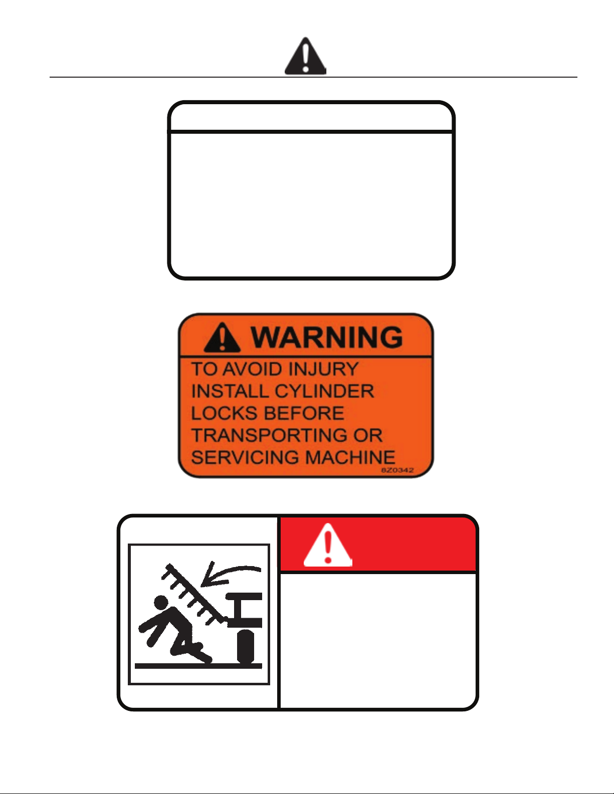
5. INSTALLING CYLINDER LOCKS DECAL (PN 8Z0342)
8Z0340
6. STAYING CLEAR OF WINGS DECAL (PN 8Z0344)
DANGER
TO AVOID INJURY OR DEATH
STAND CLEAR OF MACHINE
WHEN WINGS ARE BEING
RAISED AND LOWERED.
MECHANICAL OR HYDRAULIC FAILURE CAN ALLOW
WINGS TO FALL RAPIDLY.
8Z0344
1-3
Page 8
SAFETY
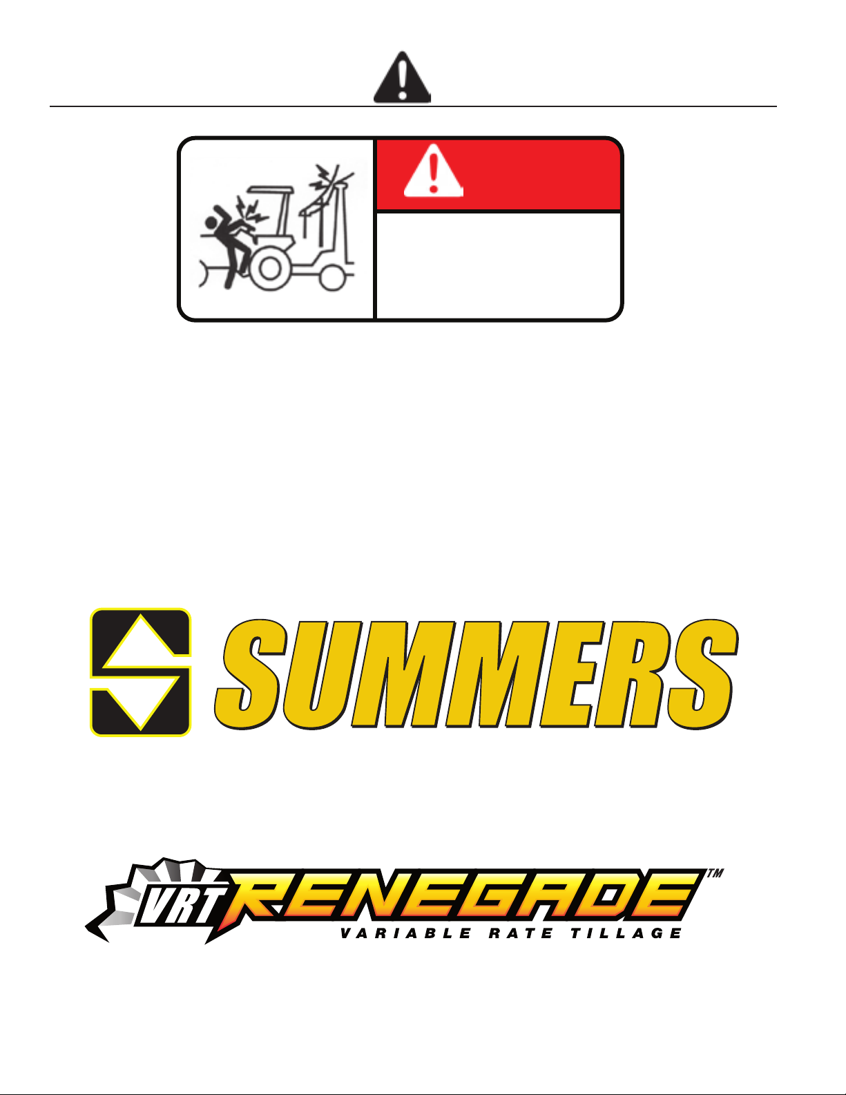
7. ELECTROCUTION DANGER DECAL (PN 8Z0346)
DANGER
TO AVOID INJURY OR DEATH
DO NOT CONTACT
ELECTRICAL LINES.
8Z0346
8. SUMMERS LOGO 8Z0202 (3.5” HIGH) AND 8Z0204 (5.5” HIGH)
9. VRT RENEGADE DECAL 8Z2550 3” HIGH AND 8Z2555 5.5” HIGH
®
1-4
Page 9
SAFETY
11. AMBER REFLECTOR (PN 8Z0800)
12. RED-ORANGE REFLECTOR (PN 8Z0805)
13. RED REFLECTOR (PN 8Z0810)
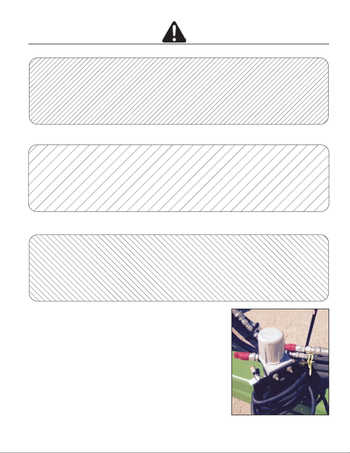
Safety Light Operation
The Summers Safety Light Kit is equipped with a 7 pin
connector which meets SAE J560 specication. To pro-
tect 7 pin connector, store in dust cap (8K8067) when not
attached to towing vehicle.
1-5
Page 10

SAFETY
1-6
Page 11
OPERATION & MAINTENANCE
CONNECTING TO THE TRACTOR
The Summers VRT Renegade is equipped
with and Articulating Ball hitch. This hitch is
designed to eliminate “slop” between the
implement hitch and the tractor drawbar.
25’ and 30’ machines are supplied with a
Category 4 hitch and must be used with a 2”
diameter hitch pin. 35’ and 40’ machines
are supplied with a Category 5 hitch and
must be used with a 2-3/4” diameter hitch
pin. A reducing bushing is also supplied to
adapt to a Category 4 drawbar.
The VRT Renegade has 3 hydraulic circuits,
Lift/Depth Control, Wing
Fold/Downpressure, and Auxiliary. After
connecting the hoses to the tractor, the flow
controls should be set as follow:
Green: Main Lift/Depth Control. Extend –
100% flow, Retract – 30%-50% flow.
Red: Auxiliary. MUST BE IN CONSTANT
FLOW, 60% flow.
Gold: Wing Fold/Downpressure. MUST
BE IN CONSTANT FLOW, 60% flow.
Alternatively, wing circuit can be run in
Float.
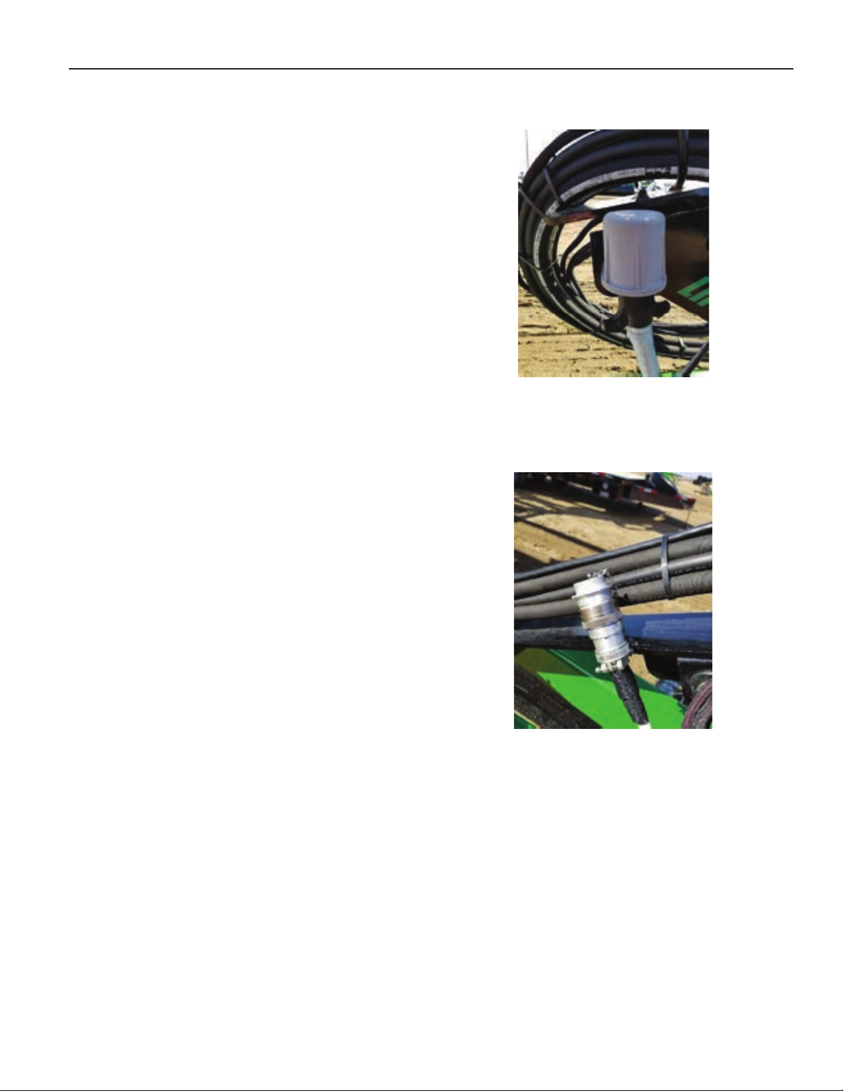
ELECTRICAL HOOKUP
The Summers Safety Light Kit is equipped
with a 7 pin connector which meets SAE
J560 specification. To protect 7 pin
connector, store in dust cap when not
attached to towing vehicle.
Connect the IBBC connector (ISO Plug) to
the tractor. The VRT Renegade does not
interface with the tractor’s CAN network, but
utilizes the connector for power and ground.
2-1
Page 12
OPERATION & MAINTENANCE
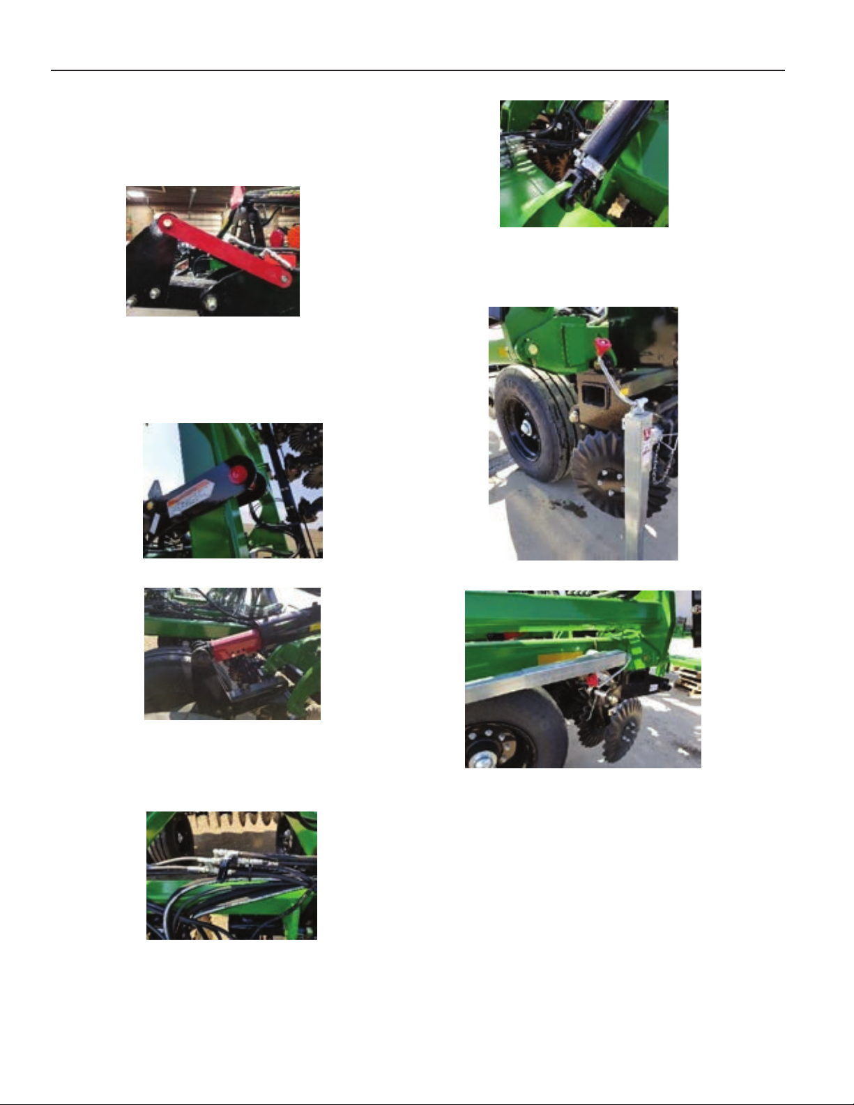
BEFORE INITIAL OPERATION
Remove the shipping locks from the center
section Rolling Baskets, shown below.
Cylinder Stops
Remove rear jack and place into storage
location.
Failure to remove shipping locks may result
in damage to the machine.
REMOVE SAFETY LOCKS
Remove wing and lift cylinder locks.
Wing Locks
Lift Cylinder Locks
Open Hydraulic Hitch Ball Valve and
remove the cylinder stops from the hitch
cylinders.
Ball Valve
Rear Jack Down
Rear Jack Stored
2-2
Page 13
OPERATION & MAINTENANCE
IPAD SETUP
Note: The minimum system requirements
for IOS version 11.
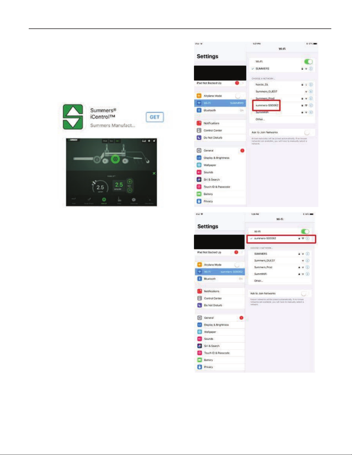
The IControl App must be downloaded from
Apple App Store. Once in the App Store,
search for “Summers IControl”.
Choose “get” once you find the App. NOTE:
You will need to log in with a valid Apple ID
in order to “get” the App.
Note: The IControl App will show
“Disconnected” unless it is connected to the
VRT Rengade’s WIFI network.
With power supplied to the machine (tractor
key in “On” or “Accessory” position) connect
the IPad to the VRT Renegade’s WIFI
network. The network name will be the
same as the serial number printed on the
Gateway 300, in this example “summersS00062”. The password for the network is
the same as the network name. Once
connected to the VRT Renegade’s network,
it will show up under the WIFI section.
2-3
Page 14
OPERATION & MAINTENANCE
STARTING THE ICONTROL APP
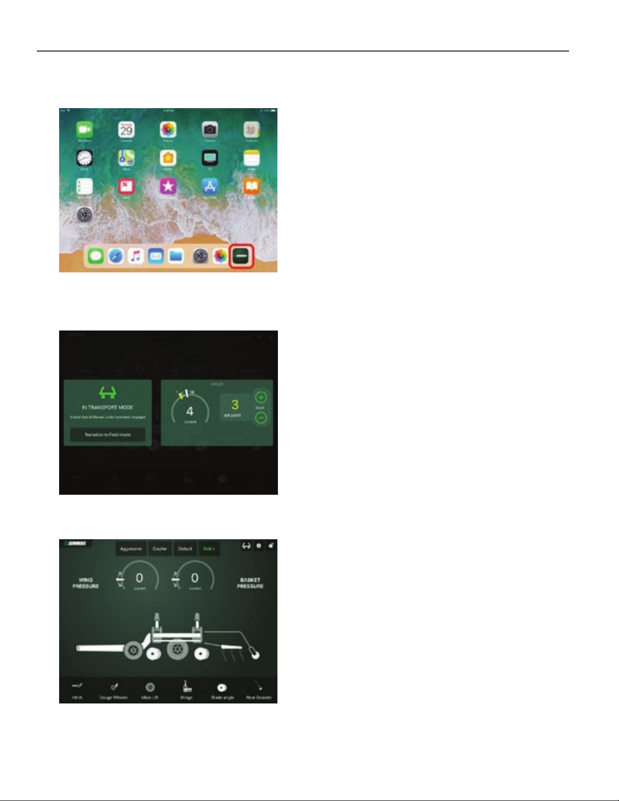
To start the app, tap the icon shown.
The app should open to one of two screens.
If the machine is in Transport Mode, the
screen should appear as shown below.
To unfold the wings, tap the “Transition to
Field Mode” button, and follow the onscreen instructions.
Note: If the machine is folded up, but the
Field Mode home screen is displayed, it
may be necessary to temporarily increase
the Wing Downpressure in order to unfold
the wings. See the “WING PRESSURE”
section for more information.
If in Field Mode, the screen should appear
as shown here.
2-4
Page 15
OPERATION & MAINTENANCE
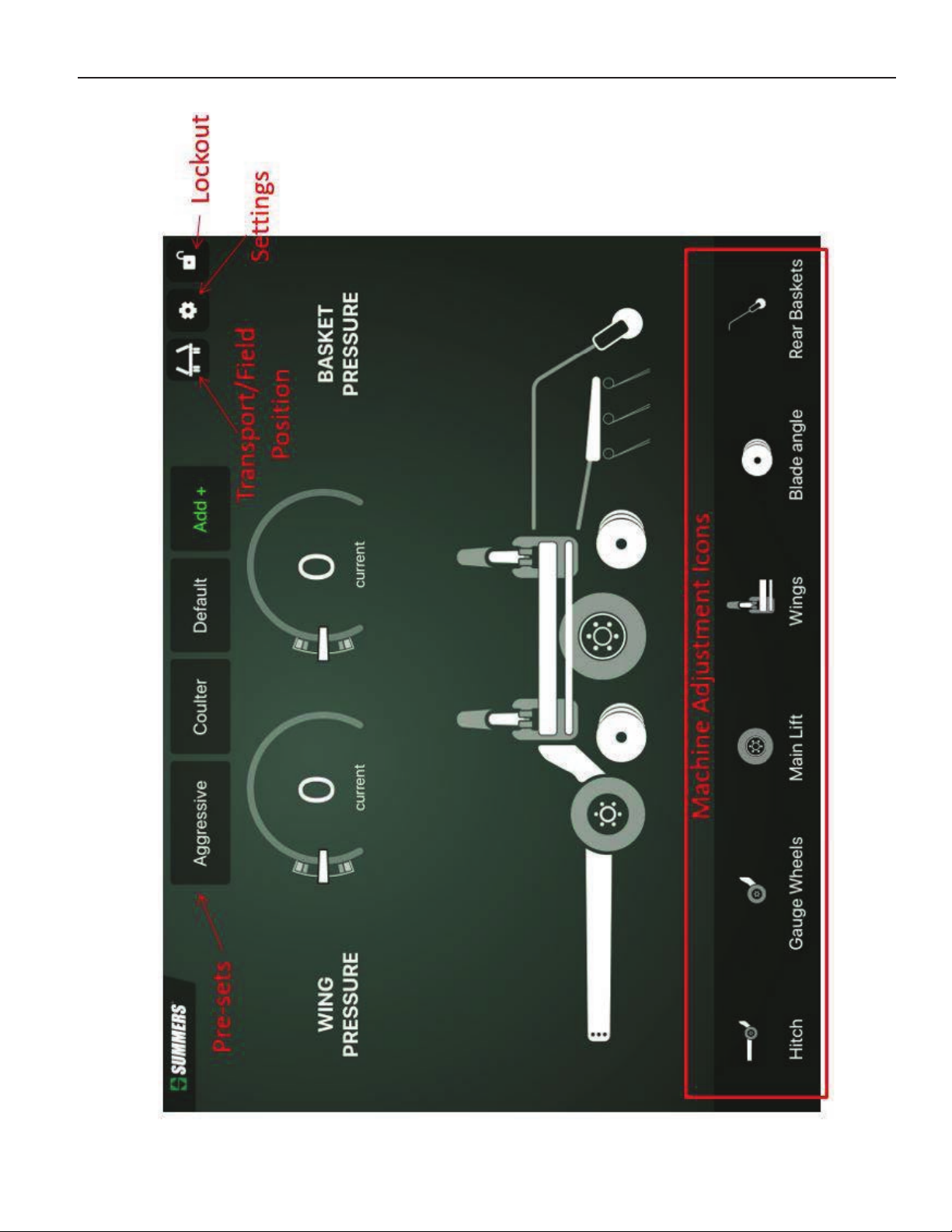
2-5
Page 16
OPERATION & MAINTENANCE
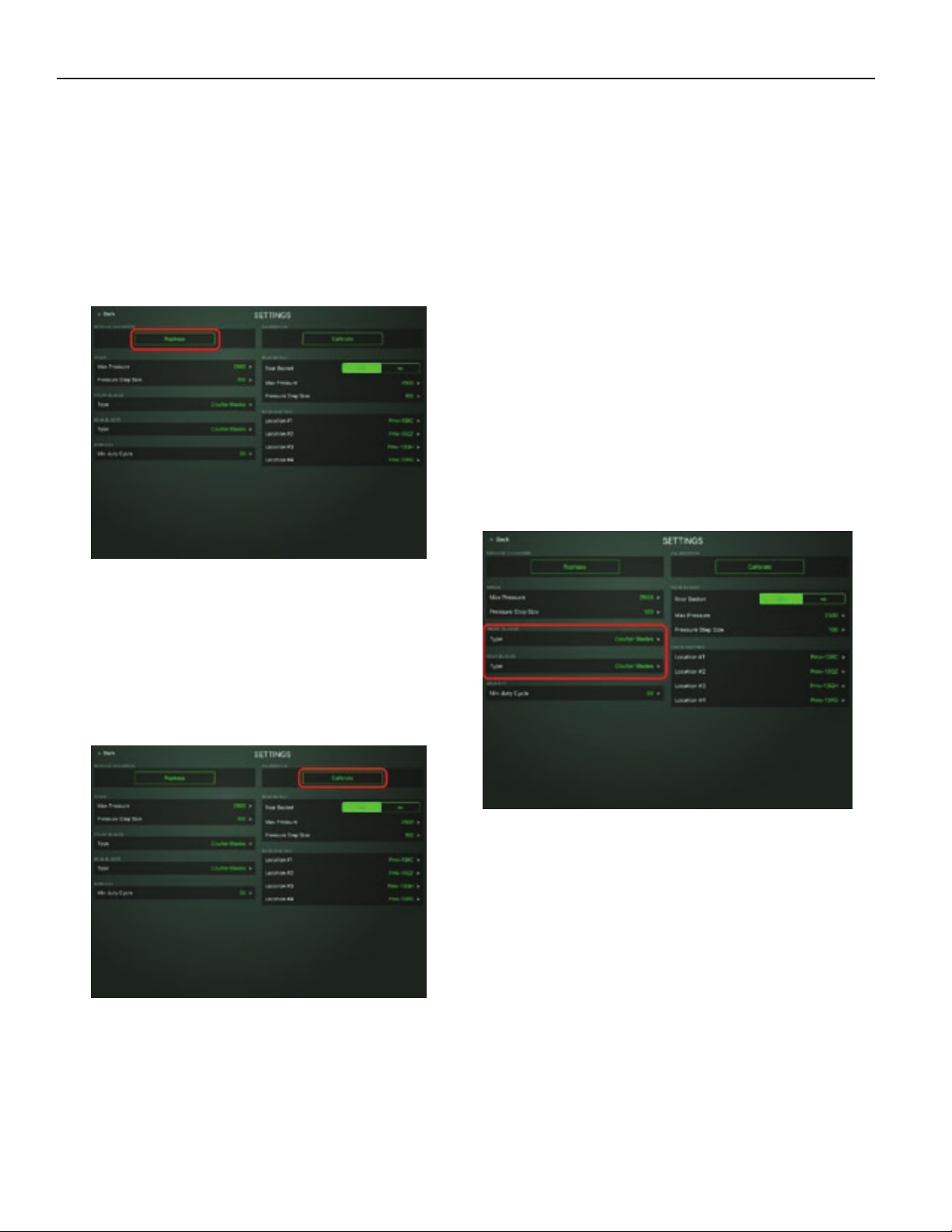
REPHASING SEQUENCE
It is recommended to run a Rephasing
Sequence at the start of, and occasionally
throughout the day. To conduct a machine
rephase, tap the Settings button on the
Home Screen. From the Settings page, tap
“Rephase” and follow the on-screen
instructions.
SELECTING BLADE TYPE
The VRT Renegade is designed to be able
to operate with different blade types. If the
machine is outfitted with Coulter Blades,
selecting this option will limit the blade angle
to 0° to 6°. This is done to protect the
blades from damage due to excessive side
draft. Likewise, if the machine is outfitted
with Disk Blades, selecting this option will
limit blade angle to 6° to 19°. Running less
than 6° on a disk blade can cause the back
side of the blade to hold up the machine, as
well as cause compaction. If the machine
has Samurai™ Blades, it can be operated at
any angle from 0° to 19°.
To select the blade type, go to the Settings
page, and select the front and rear blade
type, shown below.
CALIBRATING THE VRT RENEGADE
Any time the machine is connected to a
different tractor, or repairs are made, a
Calibration will need to be performed. To
begin the Calibration process, go to the
Settings page, and tap “Calibrate”. Follow
the on-screen instructions.
Note: It is recommended to complete a
Rephasing Sequence prior to Calibrating.
2-6
Page 17
OPERATION & MAINTENANCE
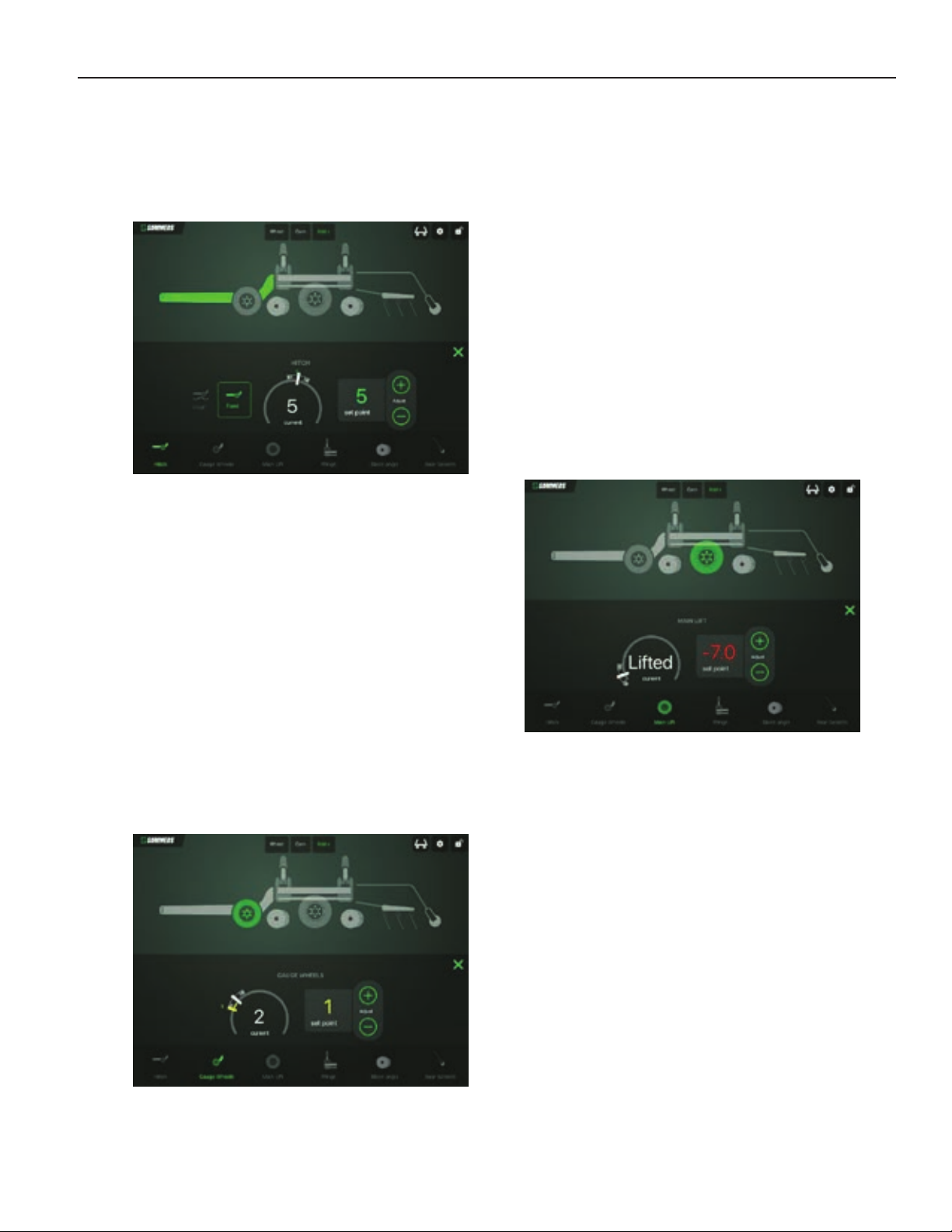
HITCH ADJUSTMENTS
To make adjustments to the Hydraulic Hitch,
tap the “Hitch” button at the bottom of the
Home Screen.
From the Hitch screen, select either “Float”
or “Fixed”. The “Float” setting will allow the
hitch to float for better contouring ability.
The “Fixed” setting allows for weight
transfer fore and aft. Increasing the Set
Point tilts the machine rearward, decreasing
the Set Point tilts the machine forward.
The Gauge Wheels can be used to level out
the machine from side-to-side, as well as
prevent “gouging” when crossing a ditch.
Increasing the Set Point lowers the Gauge
Wheels, decreasing the Set Point Raises
them.
MAIN LIFT/DEPTH CONTROL
The Main Lift of the machine is controlled by
the operator through the tractor hydraulic
remote. The IControl App is only used to
adjust the depth setting. The operator must
manually raise and lower the machine.
To change the tillage depth settings, tap the
“Main Lift” button at the bottom of the Home
Screen.
NOTE: Hitch will lock in middle position
when machine is raised and hitch is set to
“Float”.
GAUGE WHEEL ADJUSTMENTS
To make adjustments to the Gauge Wheels,
tap the “Gauge Wheels” button at the
bottom of the Home Screen.
The current position of the wheels will be
shown, as well as the Set Point. The
current position will show “Lifted” when
machine is completely raised. A negative
Set Point indicates that the target for the lift
tires is below the bottom of the blades
(holding machine out of the ground).
2-7
Page 18
OPERATION & MAINTENANCE
If no wing downpressure is desired, the
operator may place the tractor hydraulic
remote into “Float”.
Important: The wing circuit must be run
in either constant flow or float. Failure to
do so may result in damage to the
machine.
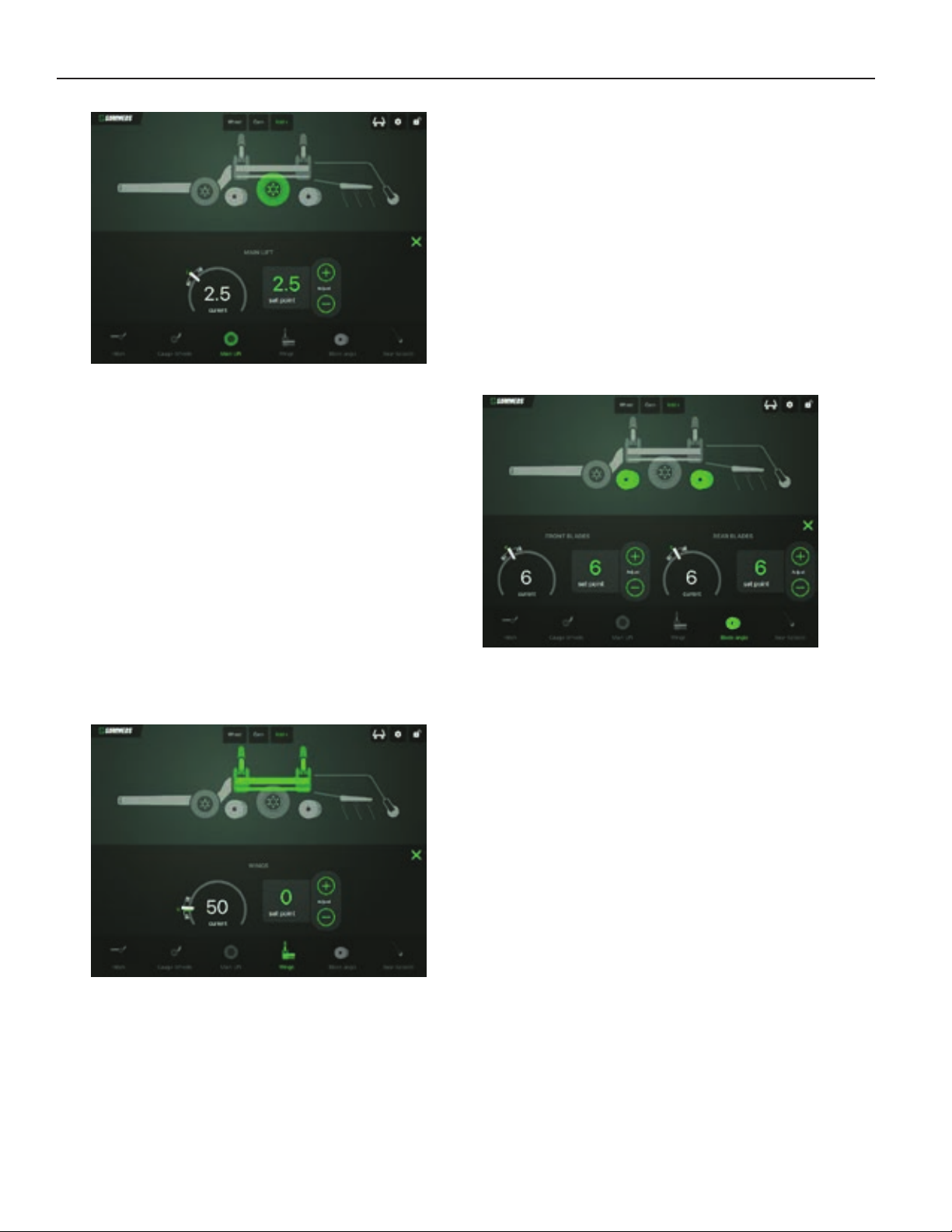
BLADE ANGLE
To make adjustments to the Blade Angle,
A positive Set Point indicates that the target
for the lift tires is above the bottom of the
blades. Increasing this Set Point will result
in deeper tillage depth.
WING PRESSURE
tap the “Blade Angle” button at the bottom
of the Home Screen.
The folding and unfolding of the wings on
the VRT Renegade is controlled by the
operator through the tractor hydraulic
remote. The IControl App is only used to
adjust the amount of downpressure applied
to the wings.
To make adjustments to the Wing
Downpressure, tap the “Wings” button at the
bottom of the Home Screen.
The current angle and the target Set Point
are displayed for both the front and rear
blades. Front and Rear blades can be
adjusted independently. The range of
adjustment available to the operator will be
dependent on the Blade Type selection
made in the Settings page.
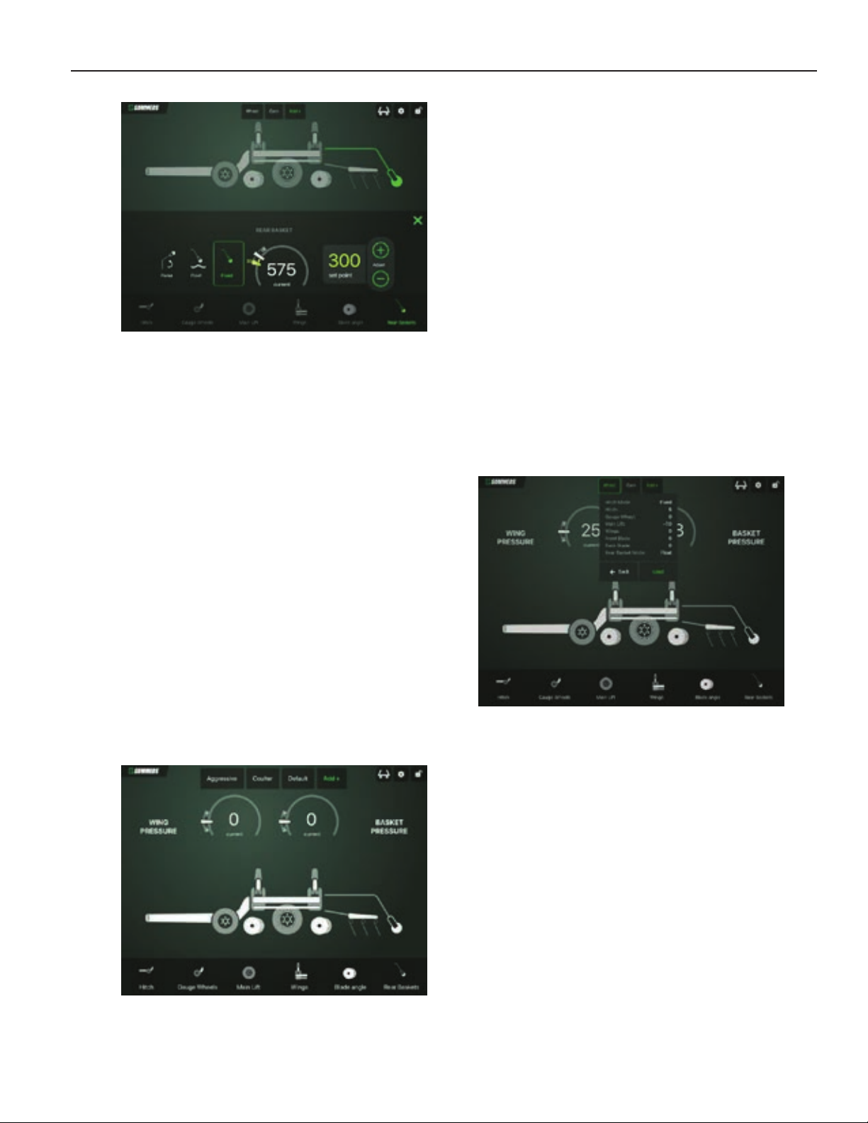
ROLLING BASKETS
To make adjustments to the Rolling
Baskets, tap the “Rear Baskets” button at
the bottom of the Home Screen.
The current hydraulic pressure, as well as
the Set Point are displayed. Increasing the
Set Point will transfer more weight from the
center frame of the machine to the wings.
2-8
Page 19
OPERATION & MAINTENANCE
Once the machine has been configured to
achieve satisfactory results, a preset can be
created by tapping the “Add +” button at the
top of the Home Screen. A custom name
can then be input for the preset. The
current machine configuration will then be
saved.
By pressing and holding on an existing
Preset, the operator can rename or
overwrite the preset.
From the Rear Baskets screen, select
“Raise”, “Float”, or “Fixed”. The Raise
setting will lift the Baskets off the ground in
the instance that the operator wishes to
utilize only the harrows. The Float setting
will allow the Baskets to “float” with no
additional downpressure. The Fixed setting
applies hydraulic downpressure. Increasing
this Set Point increased the pressure on the
baskets. When the Fixed setting is
selected, the current hydraulic
downpressure will be displayed, as well as
the target pressure.
PRESETS
The IControl App allows the operator to
create presets for machine. These presets
provide the ability to quickly change
machine settings for different conditions.
Presets are displayed at the top of the
Home Screen.
Note: If the operator wishes to “update” a
current Preset after making minor
adjustments, pressing and holding the
Preset, and tapping “overwrite” will allow
keeping the same name.
To activate a Preset, tap the desired Preset
button at the top of the Home Screen.
The operator can then view all settings in
the Preset, and then either tap “Back”, or
“Load”. “Back” returns to the Home Screen,
and “Load” will activate the Preset.
2-9
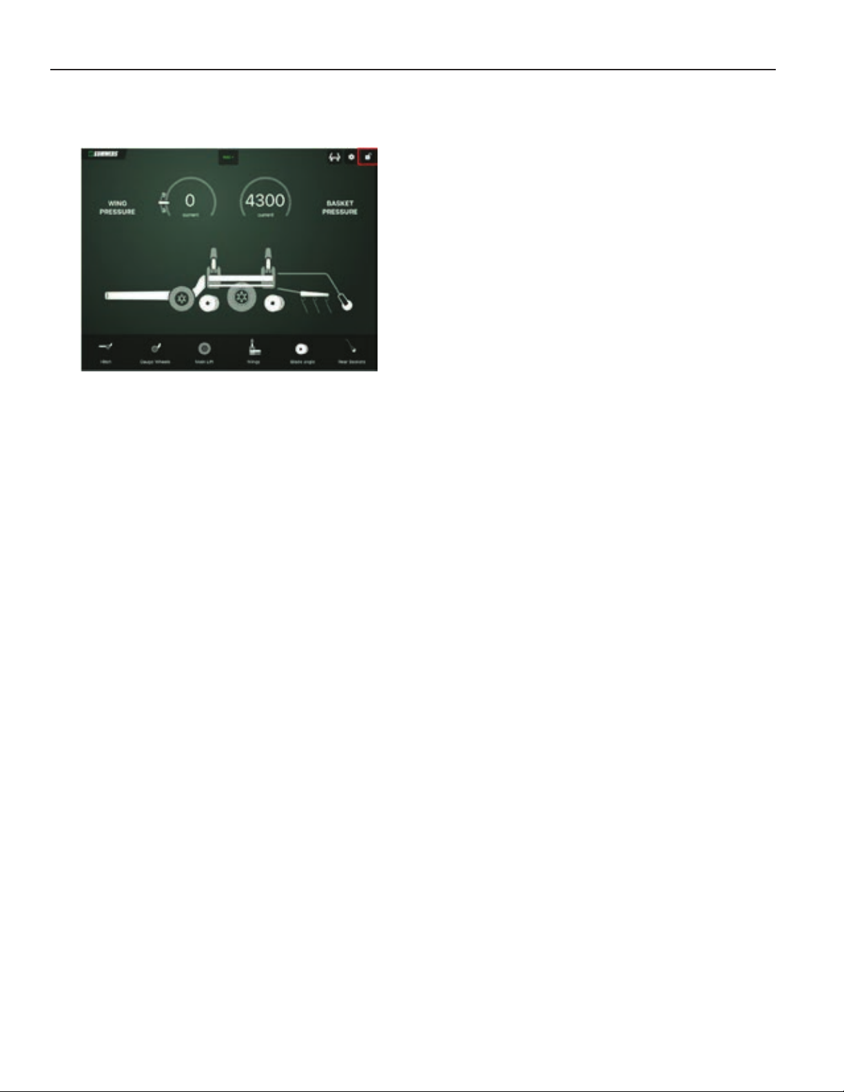
LOCKOUT MODE
To prevent accidental changes to machine
settings, as well as unexpected moving
parts if someone is near the machine, the
operator should use the “Lockout” feature
any time the machine is “active” but sitting
in one place; ex. Troubleshooting, nonoperator passenger in cab, etc.
Page 20
OPERATION & MAINTENANCE
To activate Lockout Mode, tap the Lockout
button at the top of the screen.
2-10
Page 21
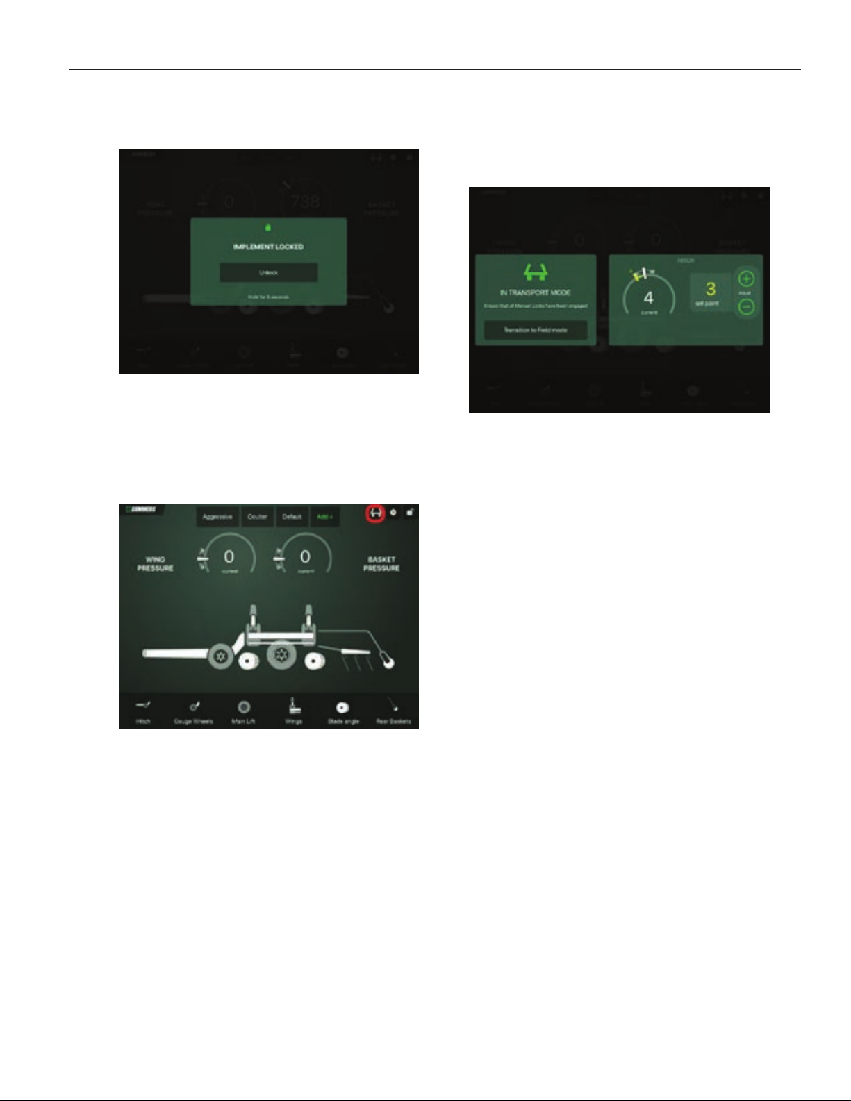
OPERATION & MAINTENANCE
This will lock the app, and not allow inputs
until unlocked.
TRANSPORT MODE
To transition to the Transport Mode, tap the
“Transport” button at the top of the Home
Screen and follow the on-screen
instructions.
At this point, the operator will be able to
make adjustments to the Hydraulic Hitch to
allow for proper balance and ground
clearance.
2-11
Page 22

OPERATION & MAINTENANCE
TRANSPORTING
Before transporting, close ball valve on
center of main frame, and install all
transport locks.
Use a safety chain between tractor drawbar
and VRT Renegade hitch when transporting
on public roads.
Check wheel bolts/nuts after first 20 miles of
road transport and every 60 miles
thereafter.
Road the implement at a reasonable speed,
not to exceed 20 MPH.
Always use an ASABE “Slow Moving
Vehicle” emblem and safety lights when
transporting on a road or highway. Comply
with your state and local laws governing
lighting and maximum width regulations.
Transport during daylight hours only.
UNHOOKING FROM VRT RENEGADE
Choose a very firm level surface to park.
Either lower wings and blades to the ground
OR install Wing and Lift Cylinder transport
locks.
Check that hitch pin is not bound with
sideways or front to back pressure. If hitch
pin is not free, carefully reposition tractor.
STORAGE
Clean dirt and debris from all electronics
and sensors.
Inspect machine for damaged or worn parts,
cracked or broken blades, and loose bolts.
Wheel bearings should be inspected
seasonally.
It is recommended to store machine
unfolded, with both the blades and tires on
the ground. If this is not feasible, ensure:
-Machine is in “Transport Mode”
-Lift Cylinder Locks are in place
-Wing Lock pins are in place
-Hitch Cylinder Stops are in place
-Hitch Ball Valve is closed
-Rolling Basket Shipping Locks are installed
-Front AND rear jacks are lowered
-Wheels are chocked
Block tires to prevent movement after hitch
pin is removed.
Lower front AND rear jacks.
Disconnect wire harnesses, hydraulic
hoses, and safety chain.
Recheck that hitch pin is free, if so, stand to
the side of the hitch and remove hitch pin.
Carefully drive ahead.
2-12
Page 23
OPERATION & MAINTENANCE
Hub
PN
Wheel Bolt/Nut
Torque
614 - 6 BOLT
8K1100
170 ft-lb
812 - 8 BOLT
8K1105
240 ft-lb
817 - 8 BOLT
8K1106
240 ft-lb
1010 - 10 BOLT
8K1109
275 ft-lb
Size
Load
Index
Pressure
VF385/65R22.5
163
70 psi
VF285/70R19.5
150
75 psi
IF280/70R15
134
64 psi
BOLT SIZE WRENCH SIZE
ft-lbs N-m ft-lbs N-m
1/4" 7/16" or 3/8" 7 9.5 12 17
5/16" 1/2" 15 20 25 34
3/8" 9/16" 30 41 45 61
7/16" 5/8" or 11/16" 45 61 70 95
1/2" 3/4" 70 95 105 142
9/16" Wheel Bolts 7/8" 170 231
5/8" 15/16" 170 231 210 285
5/8" Wheel Nuts 1-1/16" 240 325
3/4" 1-1/16"* or 1-1/8" 250 339 375 509
3/4" Wheel Nuts 1-1/8" 275 373
7/8" 1-5/16" 350 475 600 814
1" 1-1/2" 450 610 880 1193
1-1/4" 1-7/8" 500 678
1-1/2" 2-1/4" 570 773
2" 3-1/8" 1200 1627
M5 3 mm socket or 8 mm 22 in-lb 2.5 N-m
M6 4 mm socket 70 in-lb 8 N-m
*Nylon Lock Nut
GRADE 5
GRADE 8
METRIC
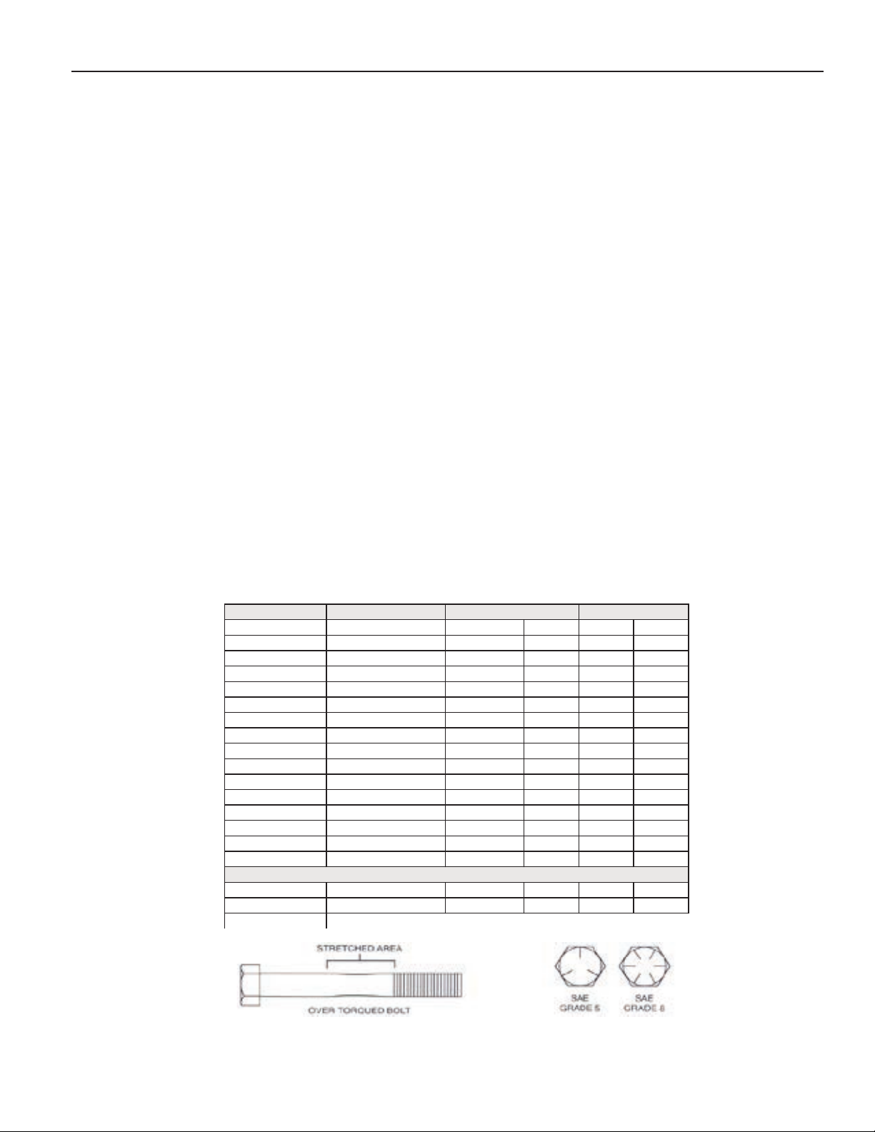
MAINTENANCE
Every 40 hours: Grease articulating ball hitch.
Seasonally: Grease Fold Cylinder Pivot.
Inspect and re-pack Wheel Bearings.
Check Wheel Bolt/Nut torque.
Tire Inflation: Recommended inflation
pressures in chart below.
PROPER BOLT USE
DO NOT use these values if a different torque value or tightening procedure is given for a
specific application. Torque values listed are for general use only. Check tightness of fasteners
periodically.
2-13
Page 24
OPERATION & MAINTENANCE
NO.
PROBLEM
PROBABLE CAUSE
CORRECTION
(tractor side)
be on extend
(-) Negative colored grip should
Calibration is found under the
the I-pad
Re-phase is found under the
the I-pad
Check sensor for movement or
damage
Increase hydraulic flow on the
tractor
the “settings” tab on the I-pad
Will need to complete the
position”
D.
Safety pins in place
Remove pins
A.
Not enough wing pressure
Increase wing pressure
B.
Gauge wheels holding up
C.
Basket pressure to high
Reduce basket pressure
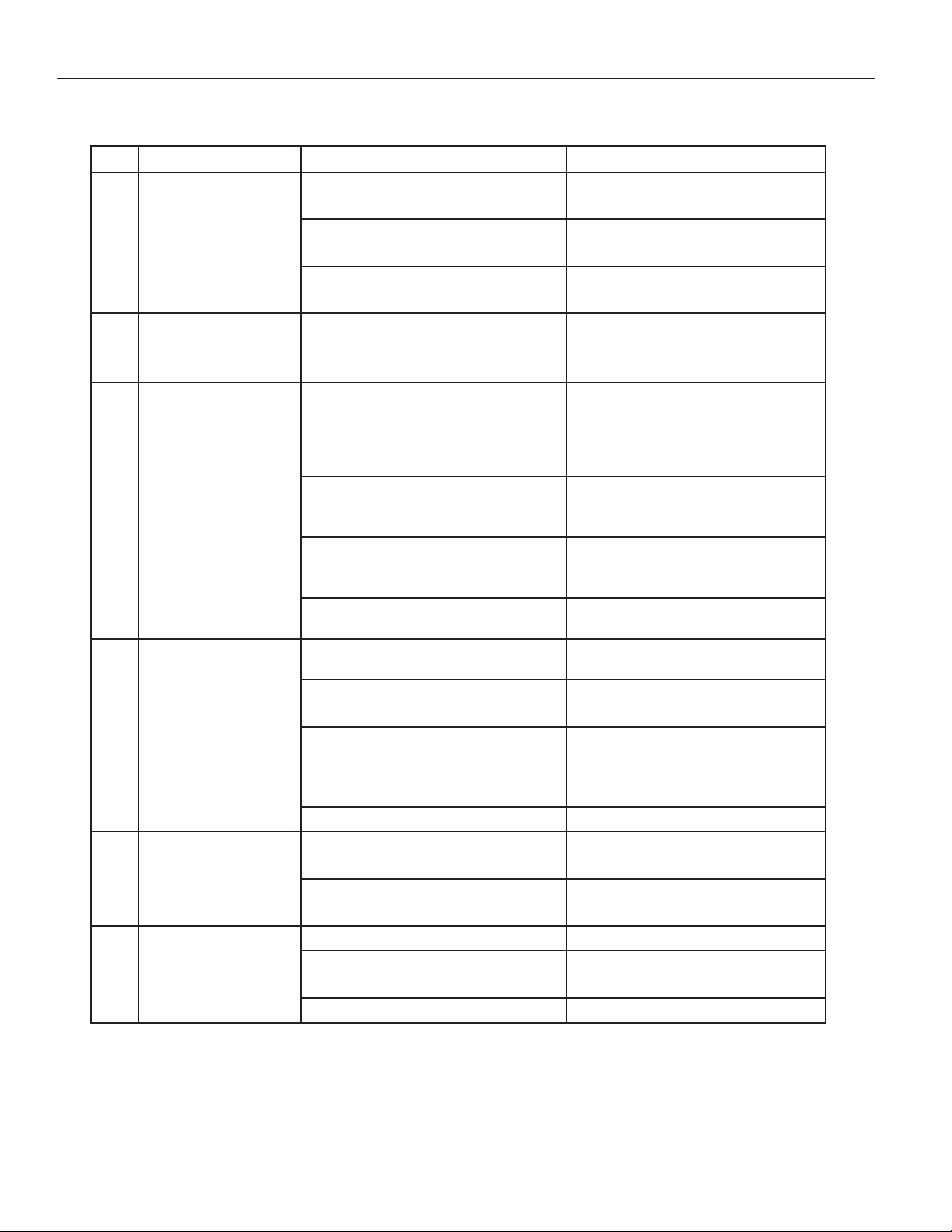
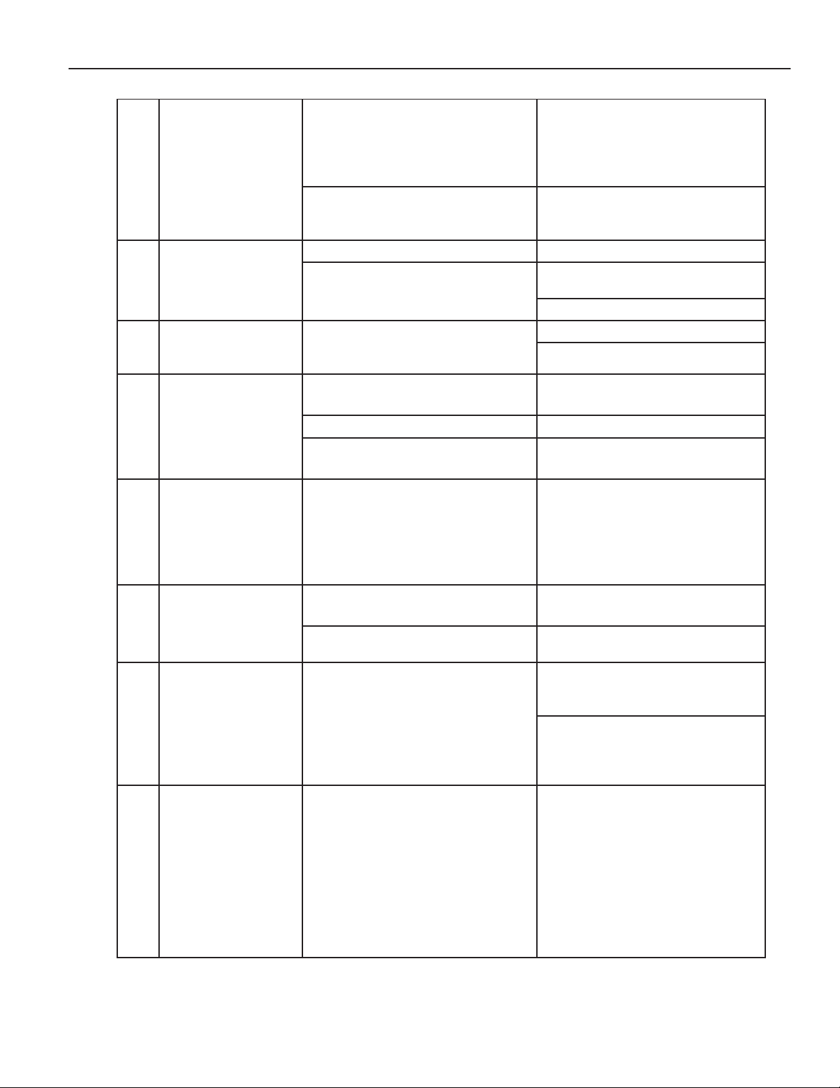
TROUBLESHOOTING
A.
I-pad will not
1
connect to Wi-Fi –
Gate Way is not lit
ISOBUS connection not
seated properly
B. No power to ISOBUS
Check connection
Check fuse or power source
May need to disconnect power
and restart procedure
Cannot find the
2
App Icon to run the
machine
I-pad settings are
not consistent
3
between “current”
and “set point”
Wings will not
4
unfold
A. App was not installed
A.
Aux hydraulic turned around
B. Re-calibration required
C. Re-phasing required
D. Sensor damage
A.
Hydraulic flow set too low
B. Max pressure setting low
C. Renegade is not in
transport mode
See section for downloading
the Summers I-Control
VRT Renegade app.
(+) Positive colored grip should
be on retract
“settings” tab on the top right of
“settings” tab on the top right of
Increase “max pressure” under
transport mode. The I-pad will
then show “entering field
Functions will not
5
respond with the Ipad
Wings are not
6
penetrating
A.
Auxiliary hydraulic is not
engaged
B. Auxiliary hydraulics are not
hooked up correctly
the wings
2-14
Engage auxiliary remote to
continuous flow
Check to see if hydraulic lines
are hooked up correctly
Retract gauge wheels
Page 25
OPERATION & MAINTENANCE
To move the machine to the
front angle or increase rear.
Float the hitch or pitch forward
move left.
A.
Wing pressure to high
Reduce wing pressure
Increase ground wheel
pressure
Increase basket pressure
VRT Renegade is
front to back
Adjust hitch angle
B.
Sensor
Check for sensor damage
Calibrate the machine found
Go to “settings” and change the
degrees.
Check position sensor for
damage
Transport mode
machine”
Close the app and restart it –
recalibration mode
Should read as such…
Upper right is #1
Upper left is #2
Lower left is #3
Lower right is #4
right, increase front angle or
VRT Renegade is
not running
7
straight or is “dog
tracking”
Wings are going in
8
too deep.
9
not running level
A.
Blade angle
B. Hitch Pitch
B. Gauge wheels not
contacting the ground
A. Hitch not in correct position
decrease rear. To move
machine to the left, decrease
to move right or pitch back to
Run hitch in float
Depth of the
machine is not
consistent to the I-
10
pad settings of the
machine
Blades will not
11
position to desired
angle
Blade angle will
12
not change
will not run
complete and is
stuck on “activate
13
cylinder extend on
main lift to raise
A.
Communication error
C. Calibration needed
Shut down tractor to break
connection and restart
under “settings”
front and/or rear blade type
Blade type setting is
A.
incorrect
setting to desired type.
Concave setting is from 6-19
degrees and coulter is 0-6
A.
Auxiliary circuit not engaged Engage Auxiliary circuit
B. Sensor
go through re-phase and
A. App not responding
Disconnect the power (tractor)
and restart
Components on
main screen
14
flashing OR the
incorrect
component moves.
A.
Mapping error
Mapping the IO400’s (check
serial numbers)
2-15
Page 26
OPERATION & MAINTENANCE
Turn the tractor off
Unplug the ISOBUS connection
Close app
Re-open app
Go to “settings” page in lower
Mapping
A.
Sensor may be bad.
Replace sensor
Use + and – buttons to move
proceed as normal
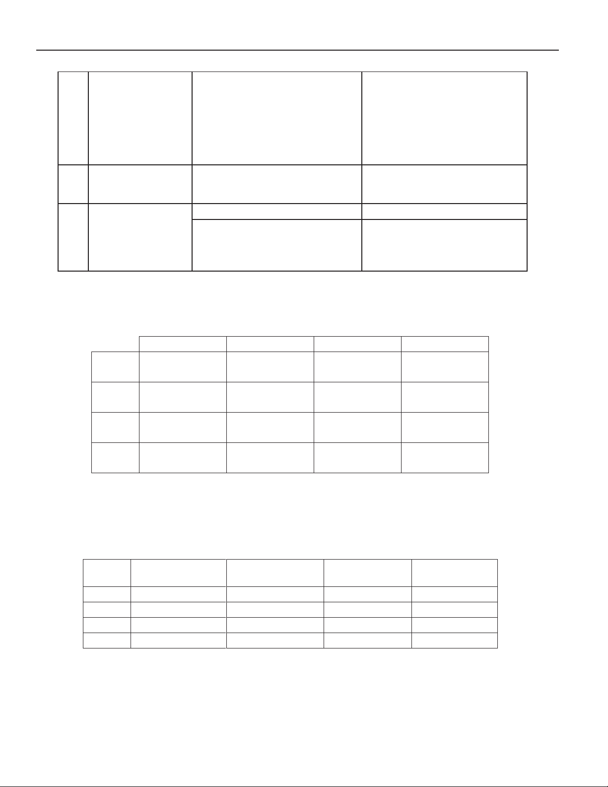
I/O 400 #1
I/O 400 #2
I/O 400 #3
I/O 400 #4
Front Blade
SIZE
TRANSPORT
WIDTH
TRANSPORT
HEIGHT
MACHINE
WEIGHT
OVERALL
LENGTH
25'
15'-6"
12'-4"
25,700
29'-10"
30'
15'-6"
14'-9"
27,000
29'-10"
35'
20'-7"
14'7"
29,380
32'-3"
40'
20'-7"
17'1"
32,100
32'-3"
I-pad isn’t
15
responding or is
locked up
A. Communication error
Double click on I-PAD home
button and “swipe” off each app
Baskets are not
16
reacting
Blade angle
shows extremely
17
high or negative
number and not
responding
BANK 1
BANK 2
BANK 3 Rear Blade Angle Hydraulic Hitch Rolling Baskets Wing Pressure
BANK 4 Rear Blade Angle Hydraulic Hitch Rolling Baskets
A.
mapped
B. App caught between
readings due to recent
recalibration
Angle
Front Blade
Angle
IO’s are not correctly
right-hand corner and set
the setting to the displayed
current value, or 0, then
I/O 400 FUNCTION LIST
Hydraulic Hitch Rolling Baskets Gauge Wheels
Hydraulic Hitch Rolling Baskets Gauge Wheels
Main Lift/Depth
Control
SPECIFICATIONS
*Dimensions and Weights are approximate
2-16
Page 27
OPERATION & MAINTENANCE
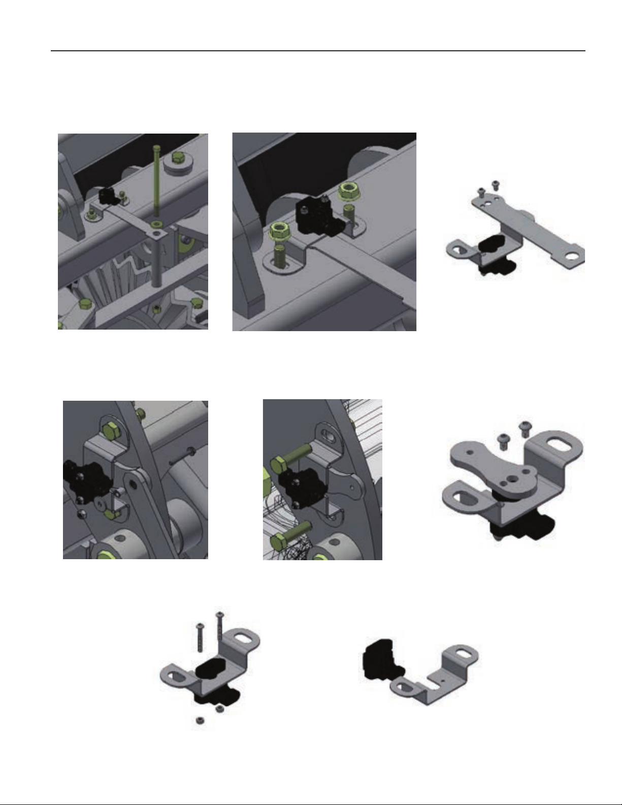
SENSOR REPLACEMENT
BLADE ANGLE SENSOR
MAIN LIFT, GAUGE WHEEL, HITCH SENSOR
NOTE ORIENTATION OF SENSOR CONNECTOR AND LEVER DIRECTION
2-17
Page 28
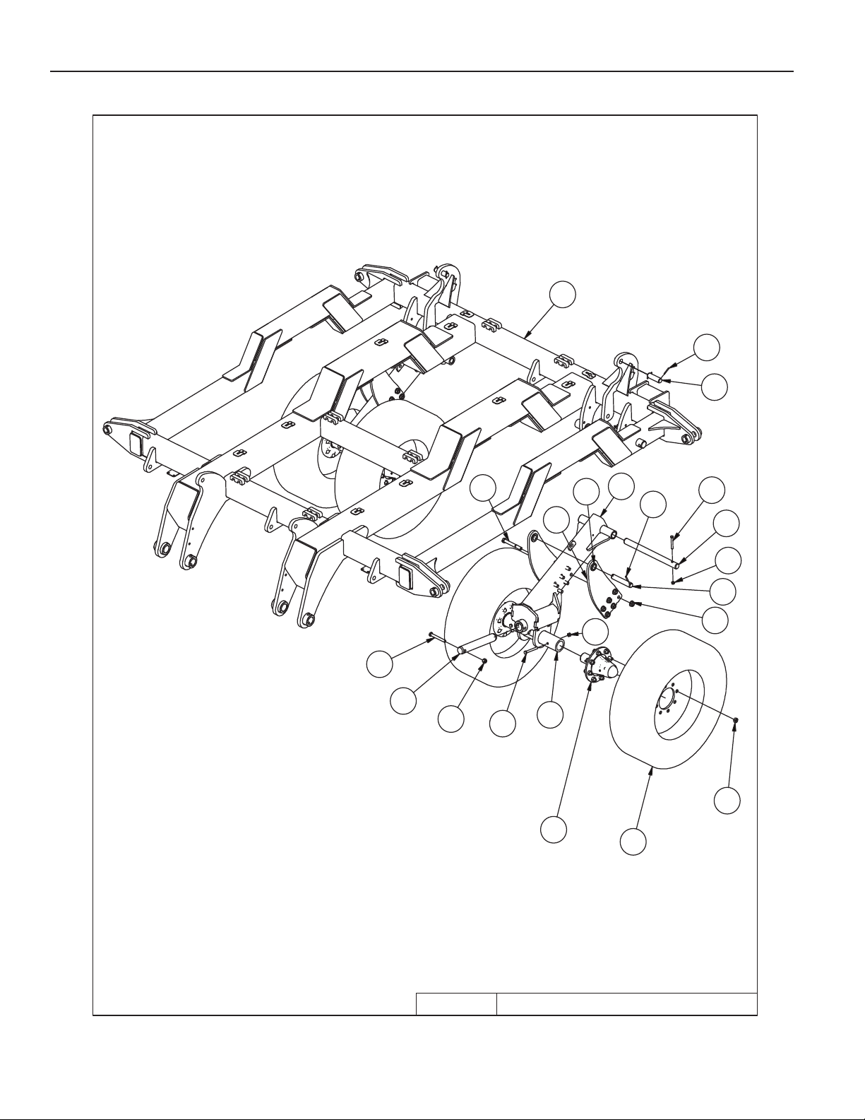
25-30' Renegade Center Trans Parts List
8P391012
8T364013
8X004414
25-30' Renegade Center Transport
4/3/2019
9
8
7
15
19
21
11
18
13
14
6
4
5
1
17
16
12
20
2
3
6
10
25-30'
RENEGADE
PARTS
3-1
Page 29
PARTS
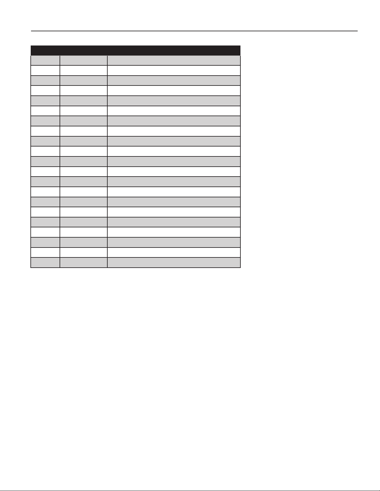
25-30’ RENEGADE CENTER TRANSPORT
ITEM PN DESCRIPTION
1 8B0025 CYL ATTCH SPACER- 1-1/4” PIN
2 8B1270B OSC AXLE SPNDLE HLDR 2.5”
3 8B2515P FRAME WING RNGD 25’-30’ R-PTD
4 8B2540 LIFTARM OSC AXL-RNGD
5 8B2542 CYL ATTCH 320/70R15
6 8D9108 ROLL PIN 1/4 X 2” YLW ZNC
7 8K1105 HUB&AXLE ASSY HD812(2.5”RCVR)
8 8K7123 NUT WHEEL BOLT 5/8-18UNF 979 8K7410 285/70R 19.5 ON 19.5X8.25X8WHL
10 8K9106 PIN 1-1/4 X 4-3/8” HARDENED
11 8K9110 PIN 1-1/4 X 6-13/16” HRDND
12 8P3910 PIN 2 X 13-1/2” HARDENED
13 8T3640 PIN 1-1/2 X 19” HARDENED 9814 8X0044 BOLT 7/16-14NC X 3-1/2”GR5 ZDI
15 8X0074 BOLT 1/2-13NC X 4-1/2” GR5 ZDI
16 8X0095 BOLT 5/8-11NC X 5” GR5 ZDI
17 8X0116 BOLT 3/4-10NC X 6” GR5 YZ
18 8X0234 NUT 7/16”-14NC NY-LOCK GR2 ZDI
19 8X0242 NUT 1/2”-13NC NY-LOCK GR2 YZ
20 8X0253 NUT 5/8”-11NC NY-LOCK GR2 YZ
21 8X0266 NUT 3/4”-10NC SER FLANG GR2 YZ
3-2
Page 30
25-30' Renegade Center Parts List
8B00051
8X001716
8X011617
PARTS
25-30'
19
4
3
18
22
13
21
15
RENEGADE
1
20 21
8
12
24
23
20
10
16
17
6
2
7
21
5
11
14
17
24
9
4/2/2019
25-30' Renegade Center
3-3
Page 31
PARTS
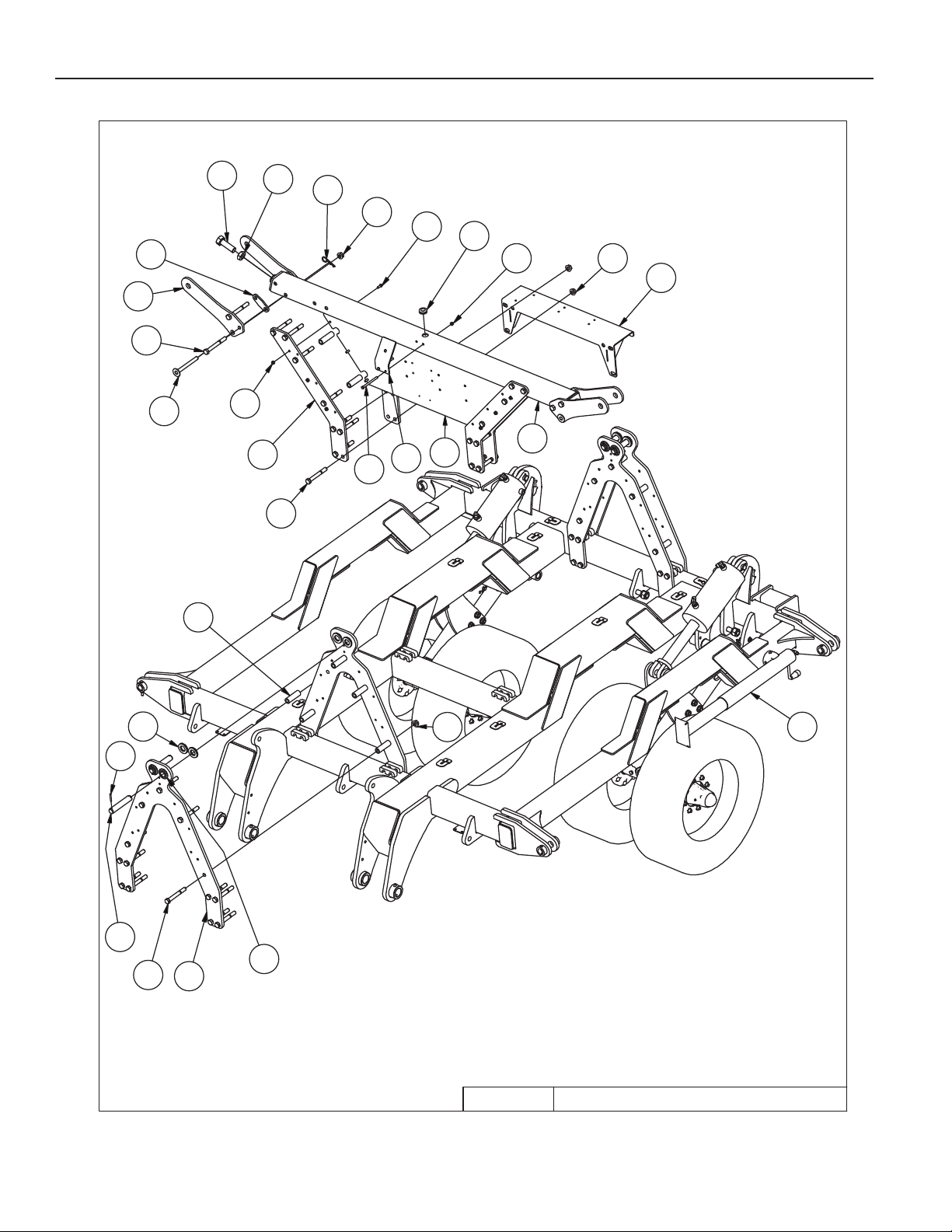
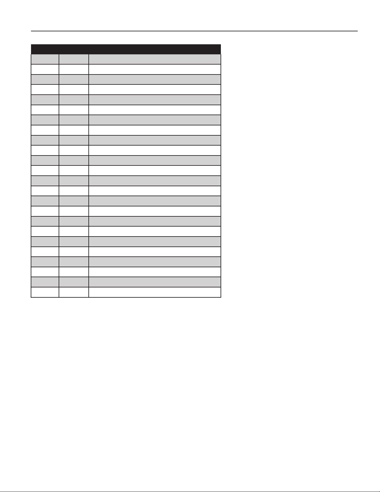
25’-30’ RENEGADE CENTER
ITEM PN DESCRIPTION
1 8B0005 GROMMET 1.75”ODX1.375”ID
2 8B0030 CONTROLLER MNT PANEL
3 8B1215 WING LOCK TAB VRT
4 8B1217 WING LOCK TAB SPCR
5 8B2532 WING REST TUBE 25’-30’
6 8B2536 SPACER .76”ID X 4”
7 8B2537 ANTENNA MNT
8 8B2538 HYD VLV BLOCK MOUNT
9 8B2558 CYL ATTCH WINFOLD 25’-30’
10 8B2560 TRANSREST MNT PLATE
11 8D8523 JACK 8000# DROPLEG 5/8X4.25PIN
12 8D9108 ROLL PIN 1/4 X 2” YLW ZNC
13 8D9110 HAIR PIN CLIP LARGE(1”CYL PIN)
14 8K9110 PIN 1-1/4 X 6-13/16” HRDND
15 8X0002 BOLT 3/8-16NC X 1” GR5 ZDI
16 8X0017 BOLT 3/8-16NC X 5” GR5 ZDI
17 8X0116 BOLT 3/4-10NC X 6” GR5 YZ
18 8X0121 BOLT 3/4-10NC X 6-1/2” GR5 YZ
19 8X0152 BOLT 1-1/4-7NC X 3.75 FULLTHD
20 8X0203 NUT 3/8”-16NC SERFLANG GR2 YZ
21 8X0266 NUT 3/4”-10NC SER FLANG GR2 YZ
22 8X0283 NUT JAM 1.25”-7NC GR2 ZDI
23 8X0325 WASHER 3/4”(13/16”ID)FLAT PLN
24 8X0327 WASHER 1-1/4” SAE FLAT YZ
3-4
Page 32
PARTS
25-30' Renegade Wings Parts List
25-30' RENEGADE WINGS
4/1/2019
25-30'
RENEGADE
31
30
22
28
26
19
21
27
17 10 18
24
16
29
23
28
2
14
13
12
27
20
21
11
15
1
7
6
21
3
27
8
5
4
30
25
8
9
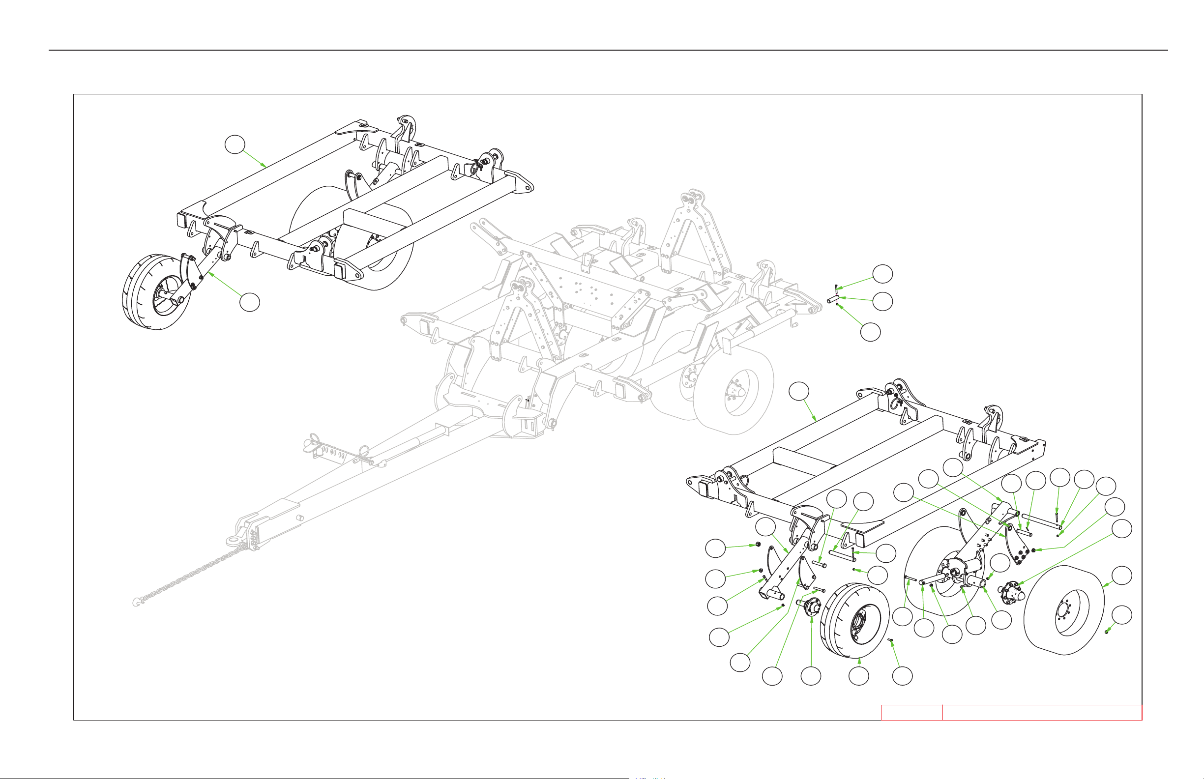
25’-30’RENEGADE WINGS
3-5
Page 33
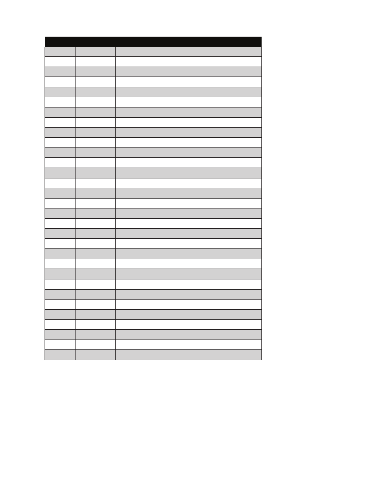
PARTS
ITEM PN DESCRIPTION
1 8B0025 CYL ATTCH SPACER- 1-1/4" PIN
2 8B1270B OSC AXLE SPNDLE HLDR 2.5"
3 8B2025 PIN 1-1/2" X 5.375" YZ
4 8B2525P FRAME WING RNGD 25'-30' L-PTD
5 8B2527P FRAME WING RNGD 25'-30' R-PTD
6 8B2540 LIFTARM OSC AXL-RNGD
7 8B2542 CYL ATTCH 320/70R15
8 8B2550 LIFTARM GAGEWHL
9 8B2551 CYL ATTCH 280/70R15
10 8D3046 IF280/70R15 134D ON 15X10X6WHL
11 8D9108 ROLL PIN 1/4 X 2" YLW ZNC
17 8K1100 HUB&AXLE ASSY 614(GBGI-2"RCVR)
12 8K1105 HUB&AXLE ASSY HD812(2.5"RCVR)
13 8K7123 NUT WHEEL BOLT 5/8-18UNF 9714 8K7410 285/70R 19.5 ON 19.5X8.25X8WHL
15 8K9110 PIN 1-1/4 X 6-13/16" HRDND
16 8P3910 PIN 2 X 13-1/2" HARDENED
18 8R6914 BOLT WHEEL 9/16"-18 UNF- 1.25"
19 8T3620 PIN 1-1/2 X 12-1/2" HRDND&ZINC
20 8T3640 PIN 1-1/2 X 19" HARDENED 9821 8X0044 BOLT 7/16-14NC X 3-1/2"GR5 ZDI
22 8X0070 BOLT 1/2-13NC X 3-1/4" GR5 YZ
23 8X0074 BOLT 1/2-13NC X 4-1/2" GR5 ZDI
24 8X0095 BOLT 5/8-11NC X 5" GR5 ZDI
25 8X0122 BOLT 3/4-10NC X 4-1/2" GR5 YZ
26 8X0138 BOLT 1-8NC X 5-1/2" GR5 ZDI
27 8X0234 NUT 7/16"-14NC NY-LOCK GR2 ZDI
28 8X0242 NUT 1/2"-13NC NY-LOCK GR2 YZ
29 8X0253 NUT 5/8"-11NC NY-LOCK GR2 YZ
30 8X0266 NUT 3/4"-10NC SER FLANG GR2 YZ
31 8X0281 NUT 1"-8NC NY-LOCK GR2 YZ
3-6
Page 34
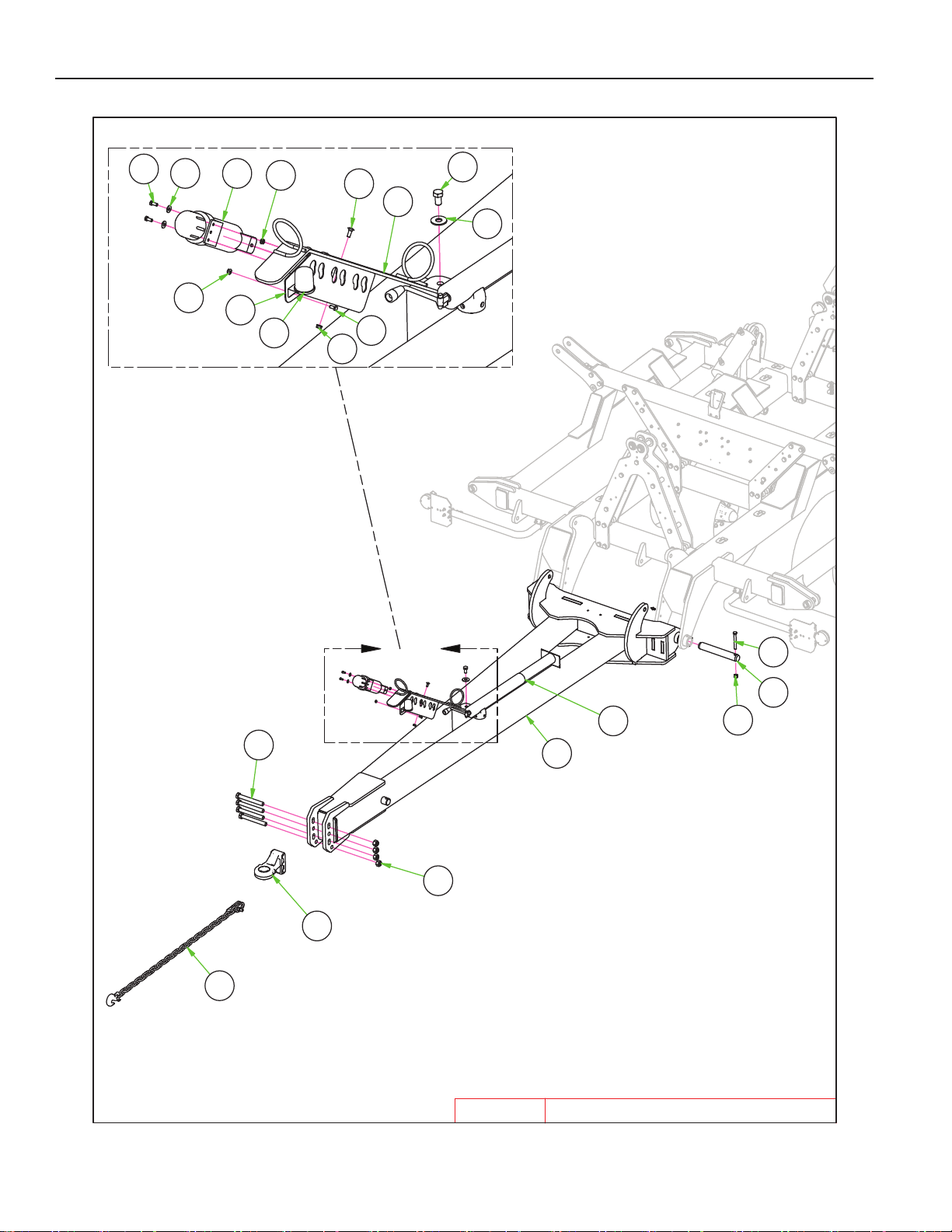
DETAIL A
A
25-30' Renegade Hitch Parts List
8N07037
8P39108
8X00219
25-30' RENEGADE HITCH
4/2/2019
9
18 20
14
14
7
5
13
9
19
6
11
17
15
8
10
1
4
16
2
3
12
25-30'
RENEGADE
PARTS
3-7
Page 35
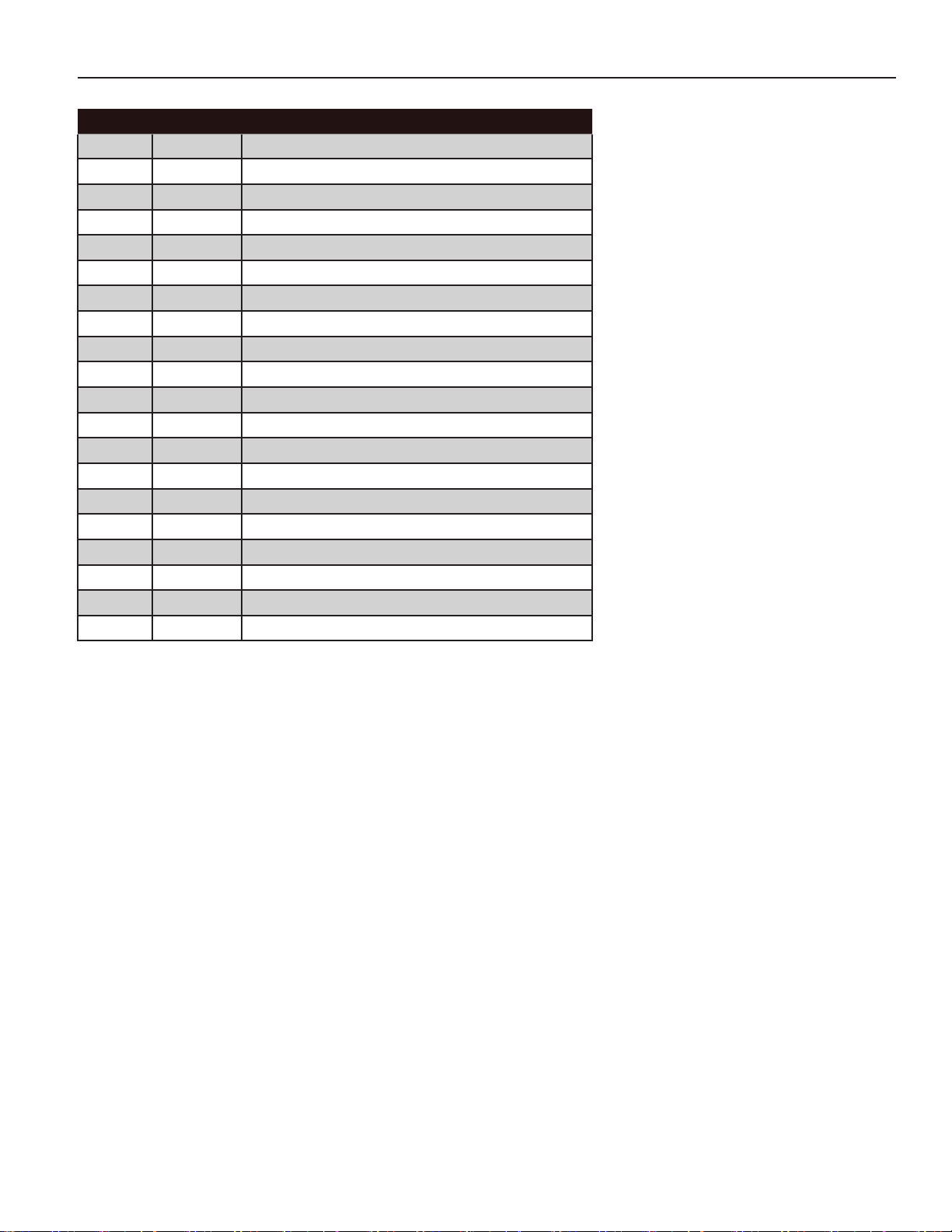
PARTS
26’-30’ RENEGADE HITCH
ITEM PN DESCRIPTION
1 8B2505P HITCH VRT RNGD 25’-30’-PTD
2 8D0760 HITCH ARTIC. BALL CAT 4
3 8D2470 SAFETY CHAIN 7/16” X 5’
4 8D8523 JACK 8000# DROPLEG 5/8X4.25PIN
5 8K8067 DUST CAP FOR 7PIN CONNECT006 8N0700 HYD HOSE ARM
7 8N0703 HYD HOSE TIP HOLDER-3 PAIR
8 8P3910 PIN 2 X 13-1/2” HARDENED
9 8X0021 BOLT 5/16-18NC X 3/4” GR5 ZDI
10 8X0095 BOLT 5/8-11NC X 5” GR5 ZDI
11 8X0110 BOLT 3/4-10NC X 1-1/4” GR5 YZ
12 8X0146 BOLT 1-8NCX8.5” W/1.5”THD GR5ZDI
13 8X0203 NUT 3/8”-16NC SERFLANG GR2 YZ
14 8X0211 NUT 5/16”-18NC SERFLANG GR2 YZ
15 8X0253 NUT 5/8”-11NC NY-LOCK GR2 YZ
16 8X0281 NUT 1”-8NC NY-LOCK GR2 YZ
17 8X0318 WASHER 3/4”(13/16”ID)FLAT YZ
18 8X0329 WASHER 5/16”(3/8” ID)FLAT YZ
19 8X1110 CRG 3/8-16NC X 1” GR2 ZN
20 8Z1010 MANUAL HOLDER TUBE
3-8
Page 36
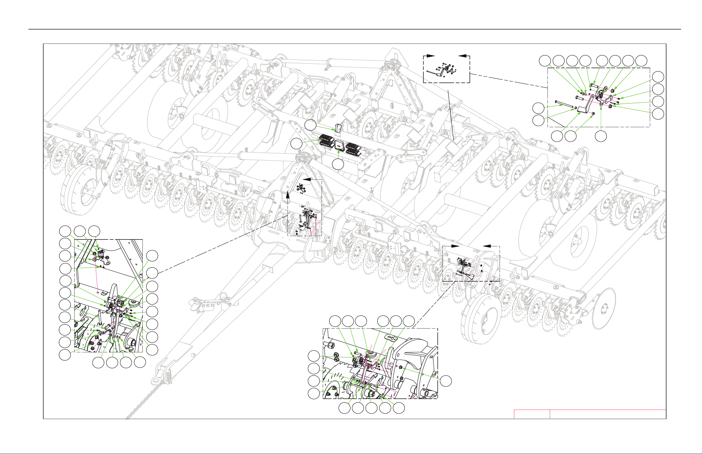
PARTS
DETAIL A
DETAIL B
DETAIL C
A
B
C
25-30' Renegade Sensor Parts List
5
7
25-30' RENEGADE SENSORS
4/4/2019
13
23
9 17
1426
20
622
5
14 2411 10 25
20
26
1
26120
11
25
15
14
8
16
23 7
25
10
24
11
1
26
23
4
3
25-30'
RENEGADE
20
2
16
12
19
21
23 12 16
19
21
24
122119
16
25
10
2024 1
11
20
3-9
Page 37
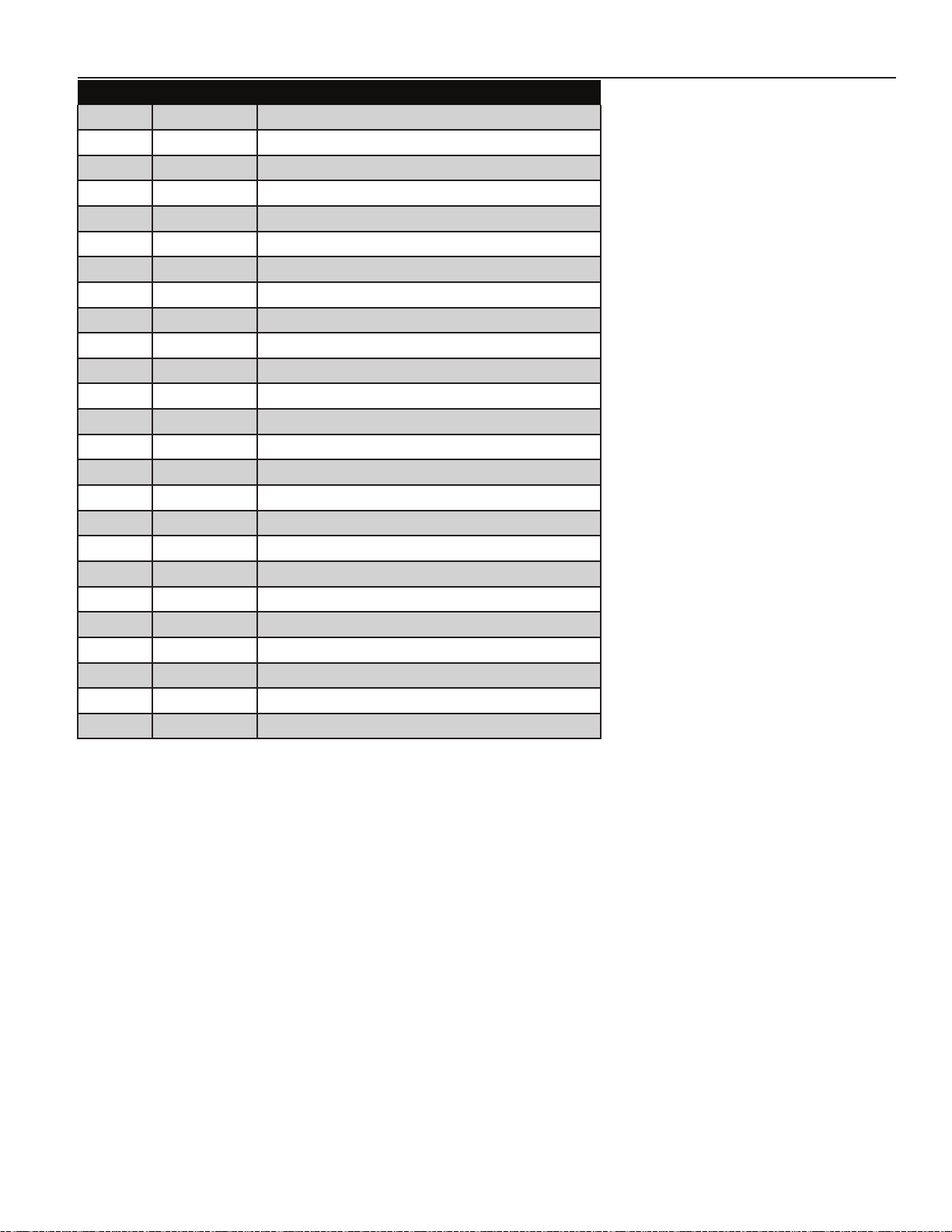
PARTS
ITEM PN DESCRIPTION
1 8B0037 ROTARY SENSOR
2 8B0038 WIFI ANTENNA
3 8B0039 GW300
4 8B0040 IO400
5 8B2835 SENSOR LINK-GAGEWHL
6 8B2836 SENSOR LINK MNT-GAGEWHL
7 8B2840 SENESOR LINK-HITCH ANGLE
8 8B2841 SENSOR LINK MNT-HITCH ANGLE
9 8B2847 SENSOR LINK-DEPTH CNTRL 25-30'
10 8B2850 SENSOR LINK-UNIVERSAL
11 8B2855 ROTARY SENSOR MNT
12 8B2860 SLEEVE #10 IDX3/8"ODX.40"
13 8X0017 BOLT 3/8-16NC X 5" GR5 ZDI
14 8X0066 BOLT 1/2-13NC X 1-3/4" GR5 ZDI
15 8X0073 BOLT 1/2-13NC X 5" GR5 YZ
16 8X0163 SCREW #10 X 1-1/4" HEX/WSHR HD
17 8X0202 NUT 3/8"-16NC NY-LOCK GR2 YZ
19 8X0206 NUT 10-24 HEX YZ NYLOCK
20 8X0246 NUT 1/2"-13NC SERFLANG GR2 YZ
21 8X0335 WASHER FENDER #10
22 8X1140 CRG 3/8-16NC X 4" GR2 ZN
23 8X3080 FLANGEBRNG .469X.375"ID- .25"
24 8XM0001 SCREW,SS - BTTN HEAD M5 X 35MM
25 8XM0110 SCREW,SS - BTTN HEAD M6 X 10MM
26 8XM0200 NUT,SS - NY-LOCK M5
3-10
Page 38
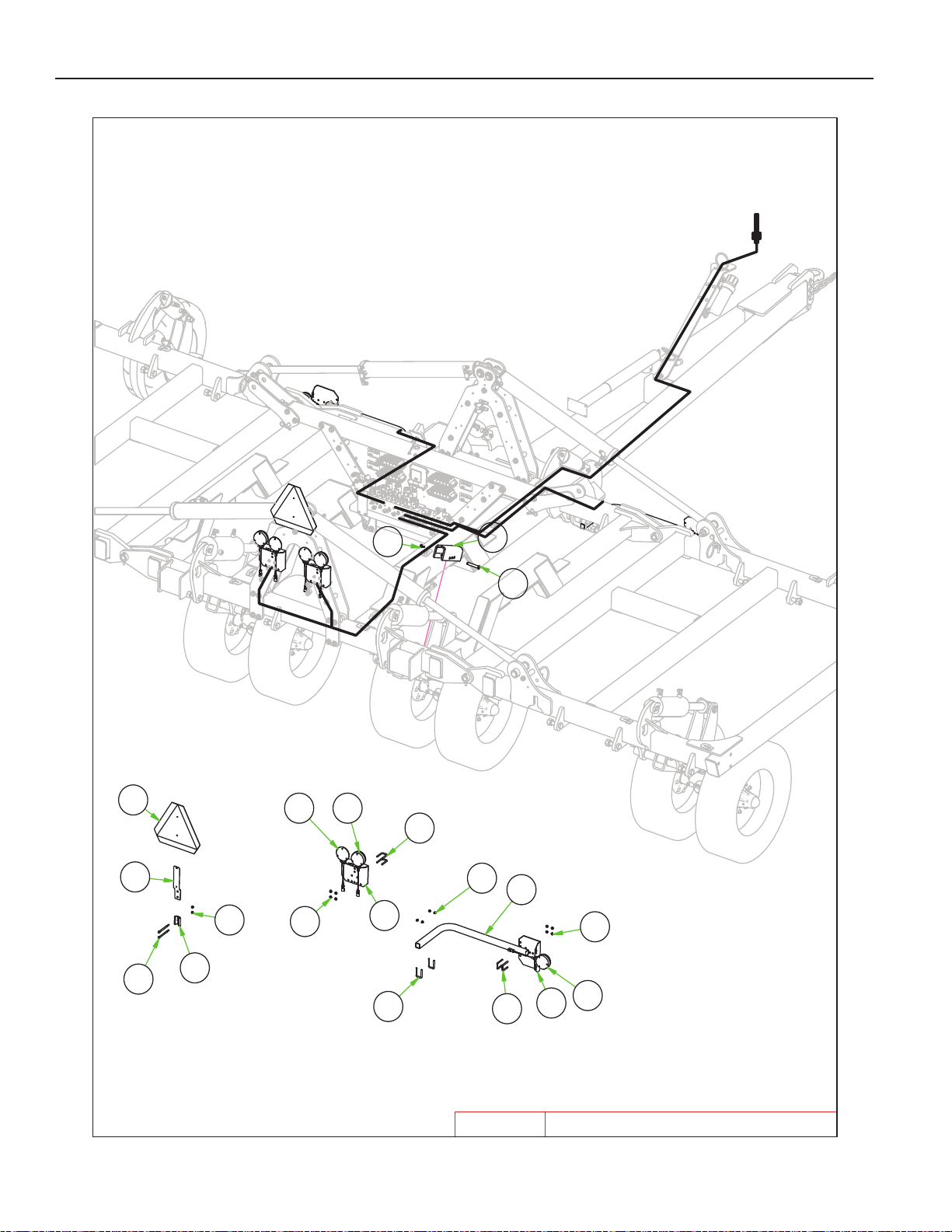
PARTS
25-30' Renegade Safety/Lighting Parts List
4
5
25-30' Renegade Safety_Lighting
4/4/2019
25-30'
RENEGADE
10
7
11
8
6
11
4 3
5
2
11
1
5
5
3
2
11
12
9
13
3-11
Page 39
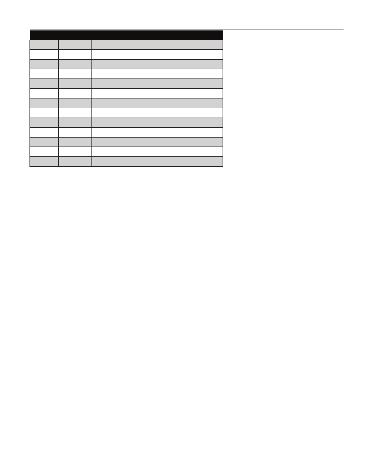
PARTS
ITEM PN DESCRIPTION
1 8K8005 TUBE LGHT BRKT SHRT 1.5SQ PNTD
2 8K8020 MOUNTNG BRCKT LIGHT 003 8K8090B LIGHT LED AMBER 2WR DTSCH 124 8K8095B LIGHT LED RED 3WIRE DTSCH 125 8L0258 U-BOLT 5/16 X 1-1/2 X 2-1/2”SQ
6 8S1120 SIGN SLOW MOVING VEHICLE(SMV)
7 8S1124 MOUNTING SOCKET SMV SIGN ZDI
8 8S1126 MNT SPADE W/HRDWR SMV SIGN
9 8T4350 TvRNS LCK W/UHMW10.5”(2.4RD)
10 8X0030 BOLT 5/16-18NC X 5” GR5 ZDI
11 8X0211 NUT 5/16”-18NC SERFLANG GR2 YZ
12 8X0402 HAIR PIN CLIP 1/8 X 2-9/16”
13 8X0440 CLEVIS PIN 5/8 X 3-7/8” ZDI
3-12
Page 40
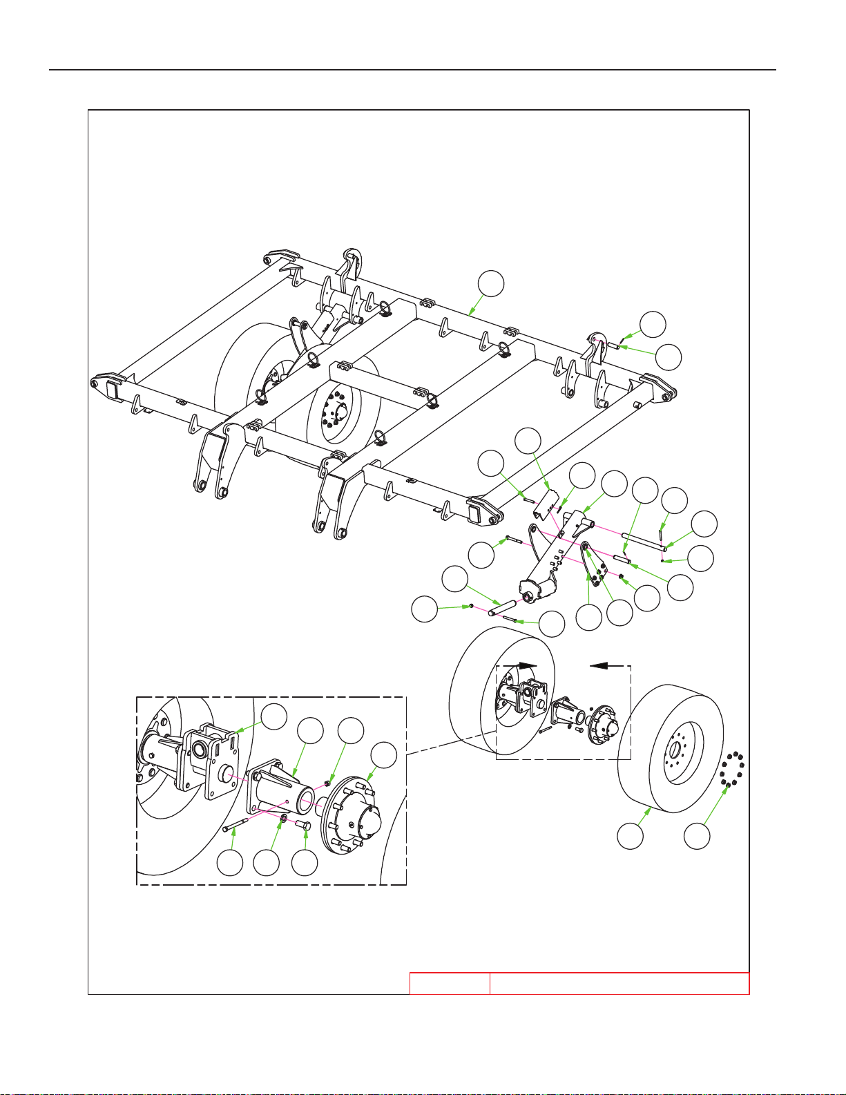
DETAIL A
A
Renegade Center Transport Parts List
8P391013
8T364014
8T435015
35-40' Renegade Center Transport
3/27/2019
17 25 20
6 22
8
7
23
13
19
18
3
26
27
15
24
4
12
21
14
16
5
5
11
2
10 9
35-40'
RENEGADE
1
PARTS
3-13
Page 41
PARTS
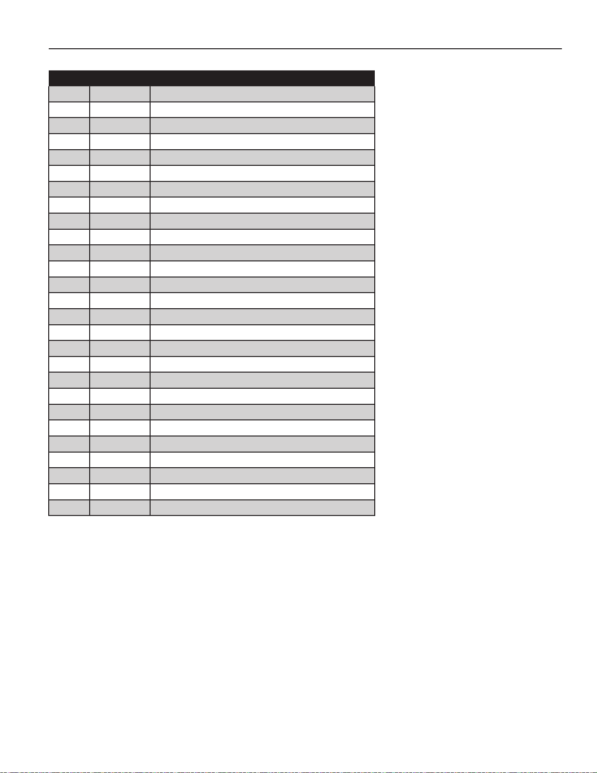
35’-40’ RENEGADE CENTER & TRANSPORT
ITEM PN DESCRIPTION
1 8B0025 CYL ATTCH SPACER- 1-1/4” PIN
2 8B2510P FRAME CENTER RNGD 35’-40’-PTD
3 8B2540 LIFTARM OSC AXL-RNGD
4 8B2541 CYL ATTCH-385/65R22.5
5 8D9108 ROLL PIN 1/4 X 2” YLW ZNC
6 8J4167 OSC AXLE SPNDLE HLDR 3.375”
7 8J4168B OSC AXLE SPNDLE HLDR MNT
8 8K1109 SPINDLE W/H1010 15K
9 8K7216 NUT 3/4”-16UNF FLANGE
10 8K7540 VF385/65R22.5-22.5X11.75X10WHL
11 8K9106 PIN 1-1/4 X 4-3/8” HARDENED
12 8K9110 PIN 1-1/4 X 6-13/16” HRDND
13 8P3910 PIN 2 X 13-1/2” HARDENED
14 8T3640 PIN 1-1/2 X 19” HARDENED 9815 8T4350 TRNS LCK W/UHMW10.5”(2.4RD)
16 8X0044 BOLT 7/16-14NC X 3-1/2”GR5 ZDI
17 8X0075 BOLT 1/2-13NC X 6” GR5 ZDI
18 8X0095 BOLT 5/8-11NC X 5” GR5 ZDI
19 8X0116 BOLT 3/4-10NC X 6” GR5 YZ
20 8X0130 BOLT 7/8-9NC X 2” GR5 ZDI
21 8X0234 NUT 7/16”-14NC NY-LOCK GR2 ZDI
22 8X0242 NUT 1/2”-13NC NY-LOCK GR2 YZ
23 8X0253 NUT 5/8”-11NC NY-LOCK GR2 YZ
24 8X0266 NUT 3/4”-10NC SER FLANG GR2 YZ
25 8X0307 LOCKWASHER 7/8” YLW ZNC
26 8X0402 HAIR PIN CLIP 1/8 X 2-9/16”
27 8X0440 CLEVIS PIN 5/8 X 3-7/8” ZDI
3-14
Page 42
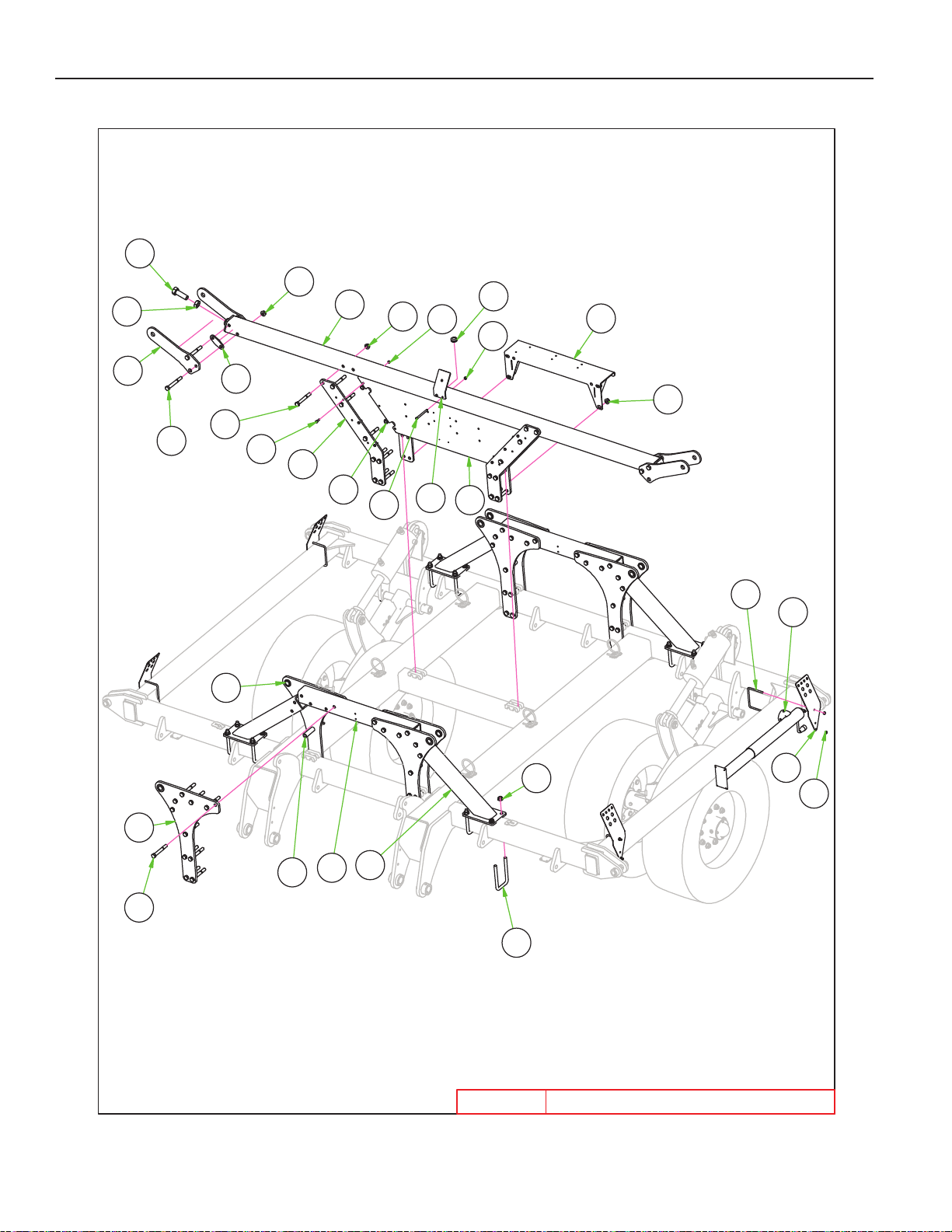
Renegade Center Parts List
8A11551
8D852316
8N020117
35-40' RENEGADE CENTER
3/26/2019
35-40'
RENEGADE
1
16
17
23
15
24
20
11
12
13
10
24
5
21
6
22
25
24
7
24
23
2
23
19
9
14
18
20
4
8
8
3
PARTS
3-15
Page 43
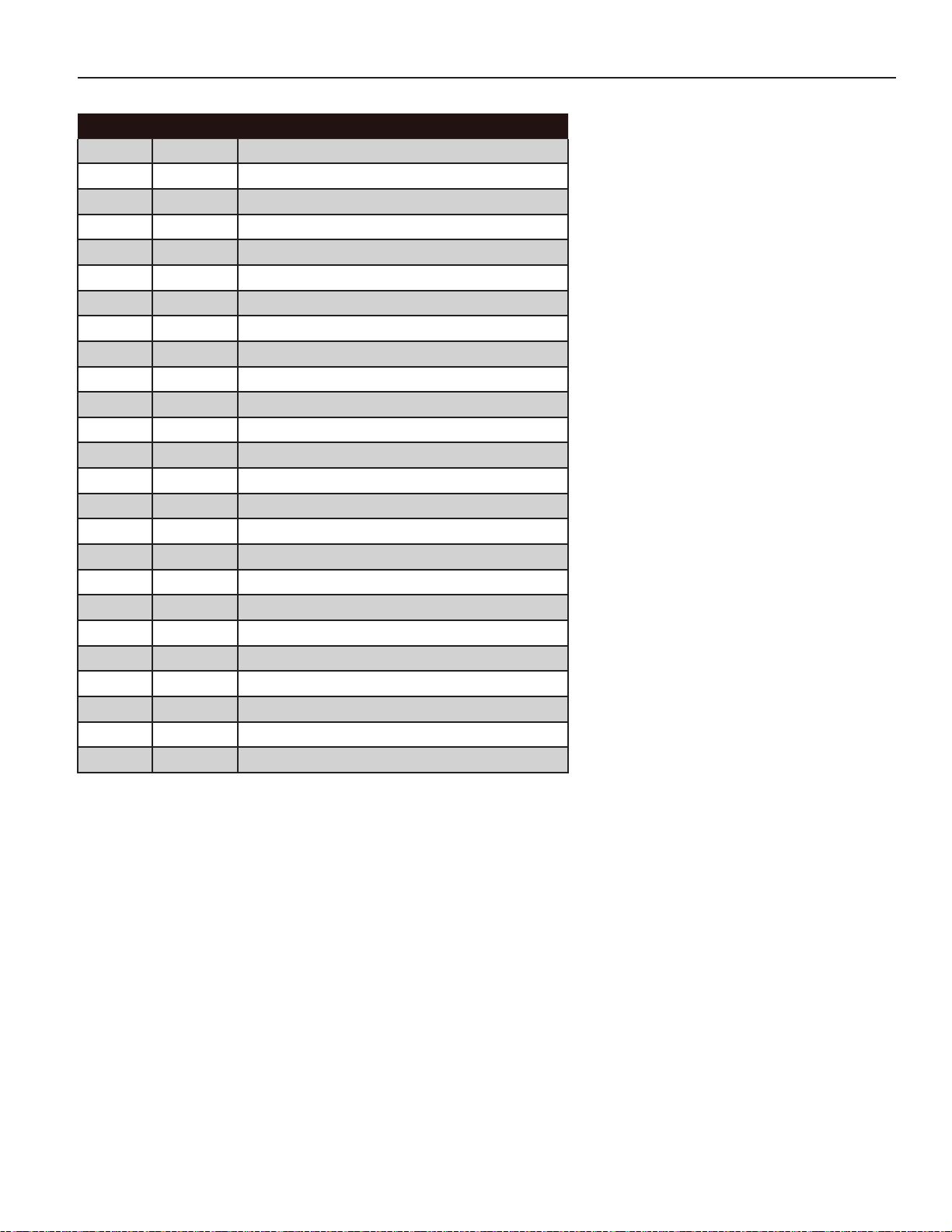
PARTS
35’-40’ RENEGADE CENTER
ITEM PN DESCRIPTION
1 8A1155 U-BOLT 3/8 X 6-1/16 X 5” SQ
2 8B0005 GROMMET 1.75”ODX1.375”ID
3 8B0025 CYL ATTCH SPACER- 1-1/4” PIN
4 8B0030 CONTROLLER MNT PANEL
5 8B1215 WING LOCK TAB VRT
6 8B1217 WING LOCK TAB SPCR
7 8B2530 WING REST TUBE 35’-40’
8 8B2536 SPACER .76”ID X 4”
9 8B2537 ANTENNA MNT
10 8B2538 HYD VLV BLOCK MOUNT
11 8B2555 CYL ATTCH WINGFOLD 35’-40’
12 8B2556 WINGFOLD CONNECTOR TUBE
13 8B2557 WINGFOLD BRACE
14 8B2560 TRANSREST MNT PLATE
15 8D0340 U-BOLT 3/4 X 4-1/16 X 7-3/4” SQ
16 8D8523 JACK 8000# DROPLEG 5/8X4.25PIN
17 8N0201 BULKHEAD PLATE - WING
18 8X0004 BOLT 3/8-16NC X 1-1/4” GR5 YZ
19 8X0017 BOLT 3/8-16NC X 5” GR5 ZDI
20 8X0116 BOLT 3/4-10NC X 6” GR5 YZ
21 8X0121 BOLT 3/4-10NC X 6-1/2” GR5 YZ
22 8X0152 BOLT 1-1/4-7NC X 3.75 FULLTHD
23 8X0203 NUT 3/8”-16NC SERFLANG GR2 YZ
24 8X0266 NUT 3/4”-10NC SER FLANG GR2 YZ
25 8X0283 NUT JAM 1.25”-7NC GR2 ZDI
3-16
Page 44
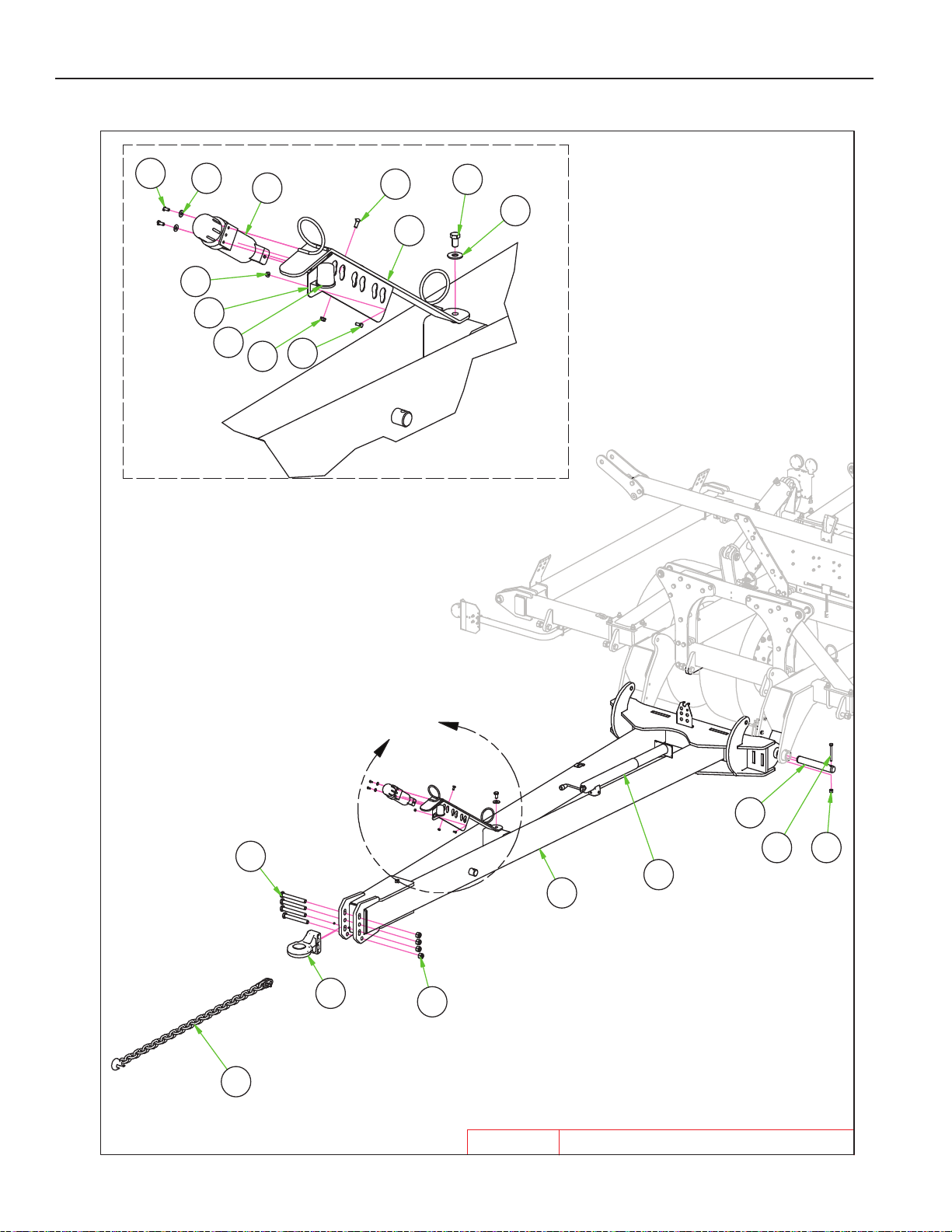
DETAIL A
A
35-40' RENEGADE HITCH
3/26/2019
35-40'
RENEGADE
11
17
19
13
9
14
20
18
9
5
6
16
2
12
8
10 15
4
1
7
3
PARTS
3-17
Page 45
PARTS
35’-40’ RENEGADE HITCH
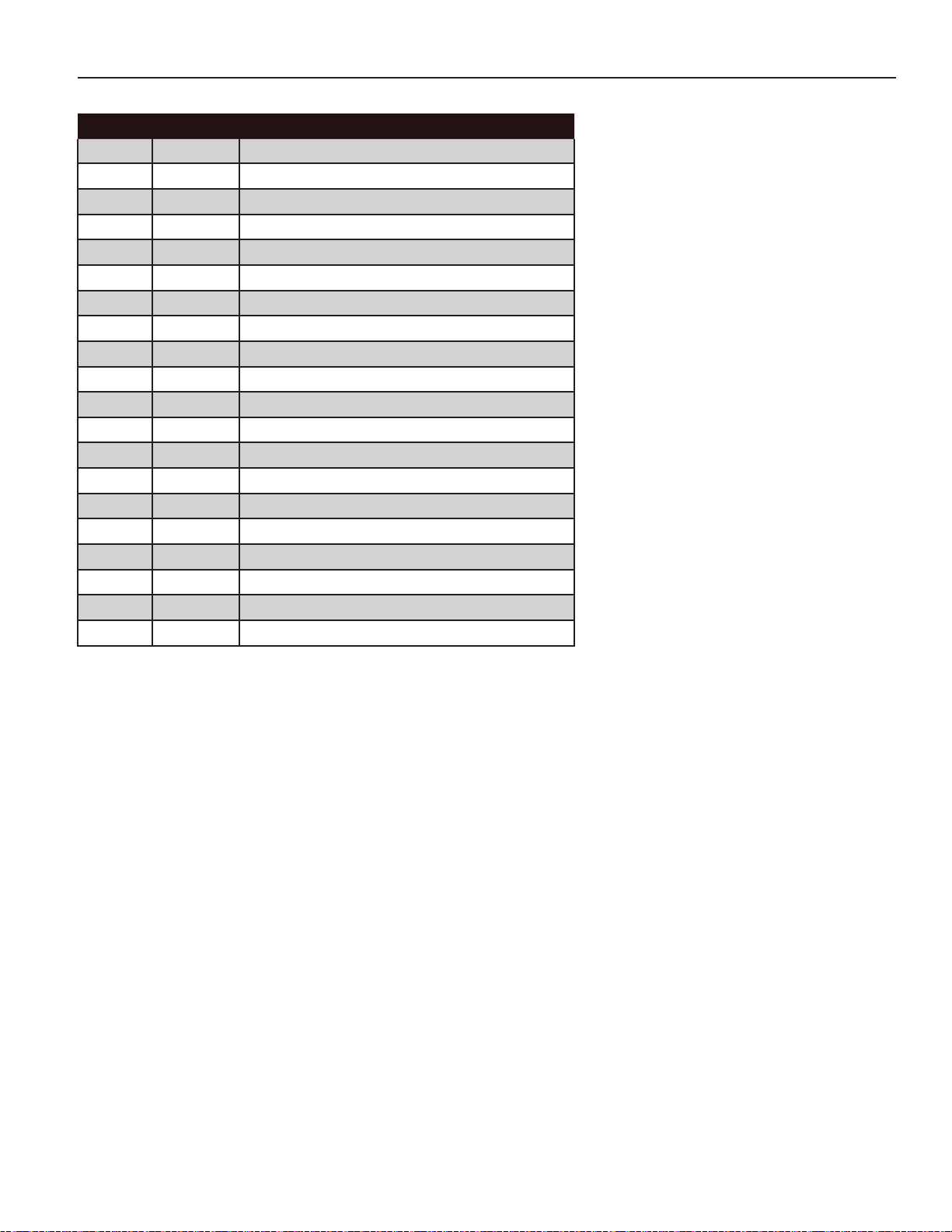
ITEM PN DESCRIPTION
1 8B2500P HITCH VRT RNGD 35’-40’-PNTD
2 8D0770 HITCH ARTIC. BALL CAT 5
3 8D2480 SAFETY CHAIN 61000# 5/8” X 66”
4 8D8523 JACK 8000# DROPLEG 5/8X4.25PIN
5 8K8067 DUST CAP FOR 7PIN CONNECT006 8N0700 HYD HOSE ARM
7 8N0703 HYD HOSE TIP HOLDER-3 PAIR
8 8P3910 PIN 2 X 13-1/2” HARDENED
9 8X0021 BOLT 5/16-18NC X 3/4” GR5 ZDI
10 8X0095 BOLT 5/8-11NC X 5” GR5 ZDI
11 8X0110 BOLT 3/4-10NC X 1-1/4” GR5 YZ
12 8X0146 BOLT 1-8NCX8.5” W/1.5”THD GR5ZDI
13 8X0203 NUT 3/8”-16NC SERFLANG GR2 YZ
14 8X0211 NUT 5/16”-18NC SERFLANG GR2 YZ
15 8X0253 NUT 5/8”-11NC NY-LOCK GR2 YZ
16 8X0281 NUT 1”-8NC NY-LOCK GR2 YZ
17 8X0318 WASHER 3/4”(13/16”ID)FLAT YZ
18 8X0329 WASHER 5/16”(3/8” ID)FLAT YZ
19 8X1110 CRG 3/8-16NC X 1” GR2 ZN
20 8Z1010 MANUAL HOLDER TUBE
3-18
Page 46
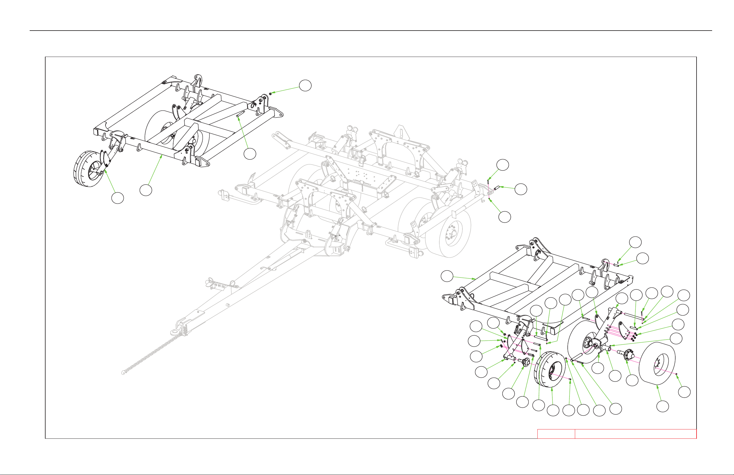
PARTS
Renegade Wing Parts List
8K110612
8K712313
8K741014
8X013828
8X023429
8X024230
35-40' Renegade Wings
3/28/2019
14
13
12
24
30
32
16
10
22
21
29
18
31
17
25
11
7
32
23
33
28
27
8
3
2
22
29
34
19
4
7
5
1
20
22
29
6
30
10
15
26
9
35-40'
RENEGADE
35-40’ RENEGADE WINGS
3-19
Page 47
PARTS
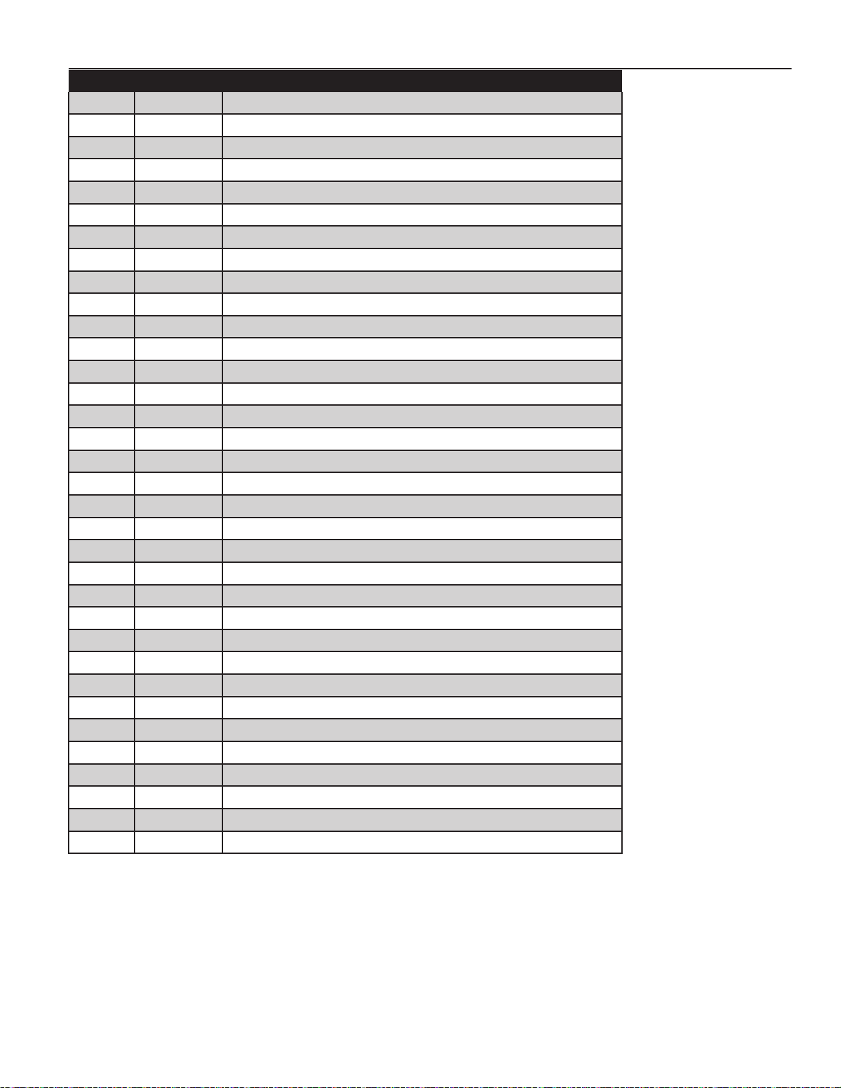
ITEM PN DESCRIPTION
1 8B1270B OSC AXLE SPNDLE HLDR 2.5"
2 8B2025 PIN 1-1/2" X 5.375" YZ
3 8B2520P FRAME WING RNGD 35'-40' L-PTD
4 8B2522P FRAME WING RNGD 35'-40' R-PTD
5 8B2540 LIFTARM OSC AXL-RNGD
6 8B2542 CYL ATTCH 320/70R15
7 8B2550 LIFTARM GAGEWHL
8 8B2551 CYL ATTCH 280/70R15
9 8D3046 IF280/70R15 134D ON 15X10X6WHL
10 8D9108 ROLL PIN 1/4 X 2" YLW ZNC
11 8K1100 HUB&AXLE ASSY 614(GBGI-2"RCVR)
12 8K1106 HUB&AXLE ASSY HD817 (2.5"RCVR)
13 8K7123 NUT WHEEL BOLT 5/8-18UNF 9714 8K7410 285/70R 19.5 ON 19.5X8.25X8WHL
15 8K9106 PIN 1-1/4 X 4-3/8" HARDENED
16 8K9110 PIN 1-1/4 X 6-13/16" HRDND
17 8P3910 PIN 2 X 13-1/2" HARDENED
18 8R6914 BOLT WHEEL 9/16"-18 UNF- 1.25"
19 8T3300 PIVOT BOLT CHSLTRP&WNGLFT YZ
20 8T3620 PIN 1-1/2 X 12-1/2" HRDND&ZINC
21 8T3640 PIN 1-1/2 X 19" HARDENED 9822 8X0044 BOLT 7/16-14NC X 3-1/2"GR5 ZDI
23 8X0070 BOLT 1/2-13NC X 3-1/4" GR5 YZ
24 8X0074 BOLT 1/2-13NC X 4-1/2" GR5 ZDI
25 8X0095 BOLT 5/8-11NC X 5" GR5 ZDI
26 8X0116 BOLT 3/4-10NC X 6" GR5 YZ
27 8X0122 BOLT 3/4-10NC X 4-1/2" GR5 YZ
28 8X0138 BOLT 1-8NC X 5-1/2" GR5 ZDI
29 8X0234 NUT 7/16"-14NC NY-LOCK GR2 ZDI
30 8X0242 NUT 1/2"-13NC NY-LOCK GR2 YZ
31 8X0253 NUT 5/8"-11NC NY-LOCK GR2 YZ
32 8X0266 NUT 3/4"-10NC SER FLANG GR2 YZ
33 8X0281 NUT 1"-8NC NY-LOCK GR2 YZ
34 8X0282 NUT 1"-14TPI TOPLOCK GR B Z
3-20
Page 48
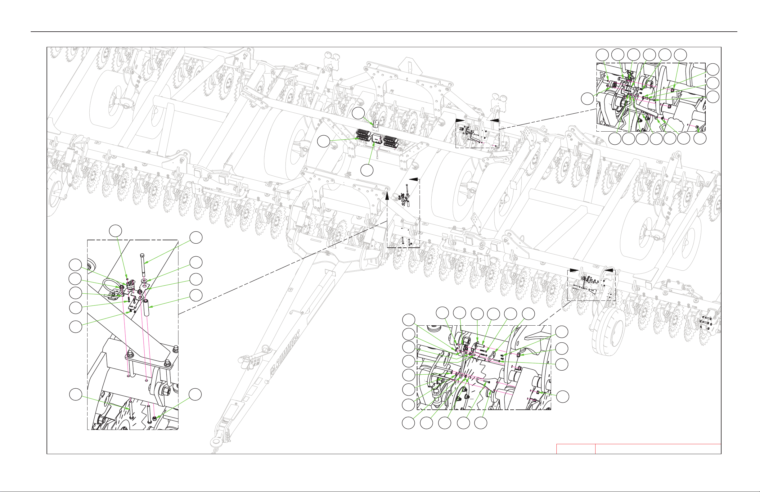
PARTS
DETAIL A
DETAIL B
DETAIL C
A
B
C
35-40' RENEGADE ELECTRICAL_SENSORS
4/1/2019
30
1
15 10
21 25 9 13
8 27 19
23
29
28
17
24
5
12
30
1
10
28
29
16 22
23
30 1
10
14
28 9
29
23
18
20
71811276
25
26
21
11
27
25
21
35-40'
RENEGADE
18
11
27
4
3
2
3-21
Page 49
PARTS
ITEM PN DESCRIPTION
1 8B0037 ROTARY SENSOR
2 8B0038 WIFI ANTENNA
3 8B0039 GW300
4 8B0040 IO400
5 8B2831 SENSOR LINK-BLADE ANGLE-FLAT
6 8B2835 SENSOR LINK-GAGEWHL
7 8B2836 SENSOR LINK MNT-GAGEWHL
8 8B2845 SENSOR LINK-DEPTH CNTRL
9 8B2850 SENSOR LINK-UNIVERSAL
10 8B2855 ROTARY SENSOR MNT
11 8B2860 SLEEVE #10 IDX3/8”ODX.40”
12 8B2865 STANDOFF .56”IDX1”ODX4.35”
13 8X0017 BOLT 3/8-16NC X 5” GR5 ZDI
15 8X0066 BOLT 1/2-13NC X 1-3/4” GR5 ZDI
16 8X0073 BOLT 1/2-13NC X 5” GR5 YZ
17 8X0082 BOLT 1/2-13NC X 6-1/2” GR5 YZ
18 8X0163 SCREW #10 X 1-1/4” HEX/WSHR HD
19 8X0202 NUT 3/8”-16NC NY-LOCK GR2 YZ
20 8X0203 NUT 3/8”-16NC SERFLANG GR2 YZ
21 8X0206 NUT 10-24 HEX YZ NYLOCK
22 8X0242 NUT 1/2”-13NC NY-LOCK GR2 YZ
23 8X0246 NUT 1/2”-13NC SERFLANG GR2 YZ
24 8X0330 WASHER 17/32”ID X 1.25”OD YZ
25 8X0335 WASHER FENDER #10
26 8X1140 CRG 3/8-16NC X 4” GR2 ZN
27 8X3080 FLANGEBRNG .469X.375”ID- .25”
28 8XM0001 SCREW,SS - BTTN HEAD M5 X 35MM
29 8XM0110 SCREW,SS - BTTN HEAD M6 X 10MM
30 8XM0200 NUT,SS - NY-LOCK M5
3-22
Page 50
PARTS
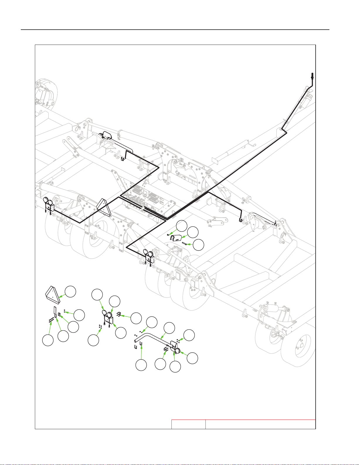
35-40' Renegade Saftey/Lighting Parts List
8K80051
8K80202
5
3/21/2019
35-40' Renegade Safety and Lighting
10
8
11
6
11
2
5
11
5
1
11
5
2
3
3
4
7
13
9
12
35-40'
RENEGADE
3-23
Page 51
PARTS
ITEM PN DESCRIPTION
1 8K8005 TUBE LGHT BRKT SHRT 1.5SQ PNTD
2 8K8020 MOUNTNG BRCKT LIGHT 003 8K8090B LIGHT LED AMBER 2WR DTSCH 124 8K8095B LIGHT LED RED 3WIRE DTSCH 125 8L0258 U-BOLT 5/16 X 1-1/2 X 2-1/2”SQ
6 8S1120 SIGN SLOW MOVING VEHICLE(SMV)
7 8S1124 MOUNTING SOCKET SMV SIGN ZDI
8 8S1126 MNT SPADE W/HRDWR SMV SIGN
9 8T4350 TRNS LCK W/UHMW10.5”(2.4RD)
10 8X0030 BOLT 5/16-18NC X 5” GR5 ZDI
11 8X0211 NUT 5/16”-18NC SERFLANG GR2 YZ
12 8X0402 HAIR PIN CLIP 1/8 X 2-9/16”
13 8X0440 CLEVIS PIN 5/8 X 3-7/8” ZDI
3-24
Page 52
Renegade Decal Parts List
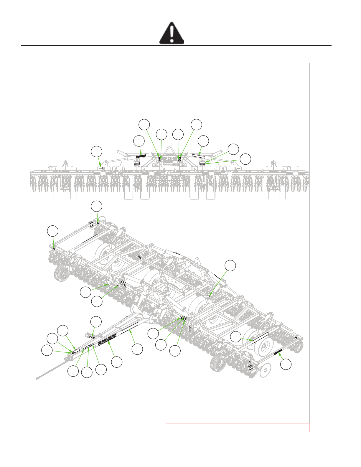
PATENT PENDING DECAL8Z00461
PATENT DECAL8Z00522
TRANSPORT LOCK DECAL8Z00753
DECAL"WARNING"PINCH POINT03-8Z00874
"WARNING" JACK DECAL8Z00995
MADE IN THE USA DECAL8Z01006
3.5" SUMMERS DECAL8Z02027
7.5" SUMMERS DECAL8Z02068
GENERAL MACHINE CAUTION DECAL
8Z02769
REPHASING CYLINDERS DECAL
8Z034010
INSTALL CYL LOCKS DECAL
8Z034211
DECAL WING DANGER8Z034412
ELECTROCUTION-TILLAG
REFLECTOR AMBER ADHSVBCK98-8Z080014
REFLCTR REDORANGE ADHSVBK99-8Z080515
REFLECTOR RED ADHSV-BACK 98-8Z081016
DECAL LIFT-AUX-WING8Z253317
DECAL - I/O #18Z254118
DECAL - I/O #28Z254219
DECAL - I/O #38Z254320
DECAL - I/O #48Z254421
3" X 20.75" VRT-RNGD DECAL8Z255022
5.5" X 20.75" VRT-RNGD DECAL8Z25552 3
SAFETY
25-40'
12
RENEGADE
19
201821
7
1
22
15
16
1
3
14
1
17
5
6
2
8
10
13
9
23
11
4
12
4/24/2019
23
7
25-40' RENEGADE DECALS
3-25
Page 53
PARTS
ITEM PN DESCRIPTION
1 8Z0046 PATENT PENDING DECAL
2 8Z0052 PATENT DECAL
3 8Z0075 TRANSPORT LOCK DECAL
4 8Z0087 DECAL"WARNING"PINCH POINT035 8Z0099 "WARNING" JACK DECAL
6 8Z0100 MADE IN THE USA DECAL
7 8Z0202 3.5" SUMMERS DECAL
8 8Z0206 7.5" SUMMERS DECAL
9 8Z0276 GENERAL MACHINE CAUTION DECAL
10 8Z0340 REPHASING CYLINDERS DECAL
11 8Z0342 INSTALL CYL LOCKS DECAL
12 8Z0344 DECAL WING DANGER
13 8Z0346 ELECTROCUTION-TILLAGE EQUIP. DECAL
14 8Z0800 REFLECTOR AMBER ADHSVBCK9815 8Z0805 REFLCTR REDORANGE ADHSVBK9916 8Z0810 REFLECTOR RED ADHSV-BACK 9817 8Z2533 DECAL LIFT-AUX-WING
18 8Z2541 DECAL - I/O #1
19 8Z2542 DECAL - I/O #2
20 8Z2543 DECAL - I/O #3
21 8Z2544 DECAL - I/O #4
22 8Z2550 3" X 20.75" VRT-RNGD DECAL
23 8Z2555 5.5" X 20.75" VRT-RNGD DECAL
3-26
Page 54
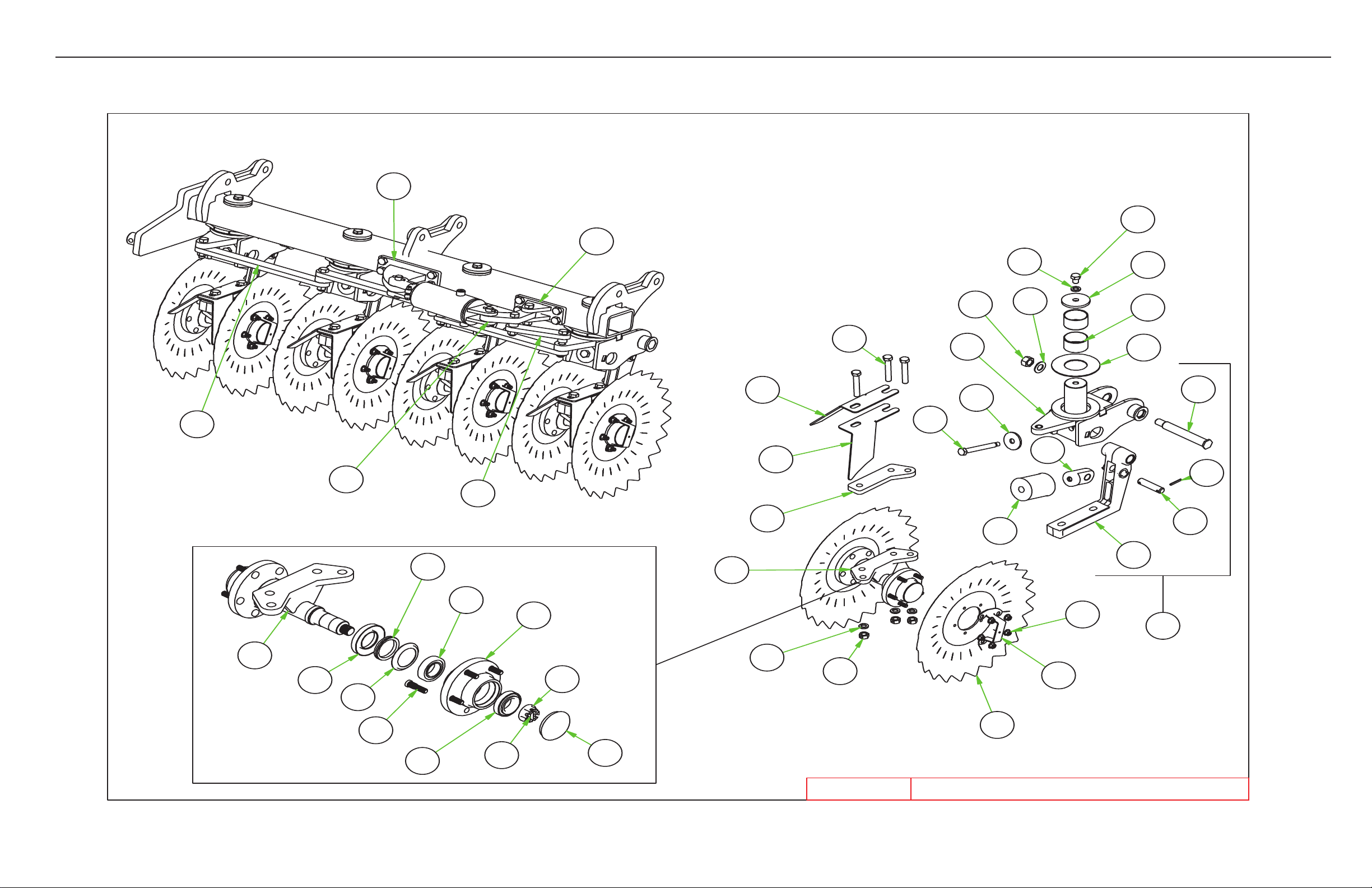
7/25/2019 BLADE MODULE 35'-40' CNTR L-R
9
8
24
23
19
21
28
30
20
3
12
22
25
4
1
5
32
2
31
29
27
7
33
18
30
26
1
7
6
10
9
2
10
4
8
5
3
6
14
13
15
16
17
PARTS
35-40’ RENEGADE WINGS
3-27
Page 55
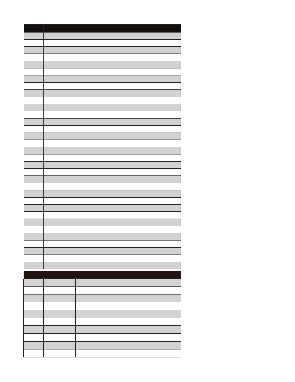
PARTS
ITEM PN DESCRIPTION
1 8B0015 TRIP BUMP STOP
2 8B0062B HOUSING W/SHAFT-DISK TRIP
3 8B0065 ARM - DISK TRIP
4 8B0069 PRELOAD PIVOT W/BUSH
5 8B0070 TRIP ASSY HEX HEAD SHLDR BOLT
6 8B0080B DISK TRIP-PIVOTING
7 8B0156B 3.06”X6.5”X .157” THRUST WASHER
8 8B2000P VRT SCRAPER OUTER-L PNTD
9 8B2002P VRT SCRAPER INNER-L PNTD
10 8B2005P VRT SCRAPER OUTER-R PNTD
11 8B2007P VRT SCRAPER INNER-R PNTD
12 8B2028 PIN 1” X 4.25 YZ
13 8B2800 BLADE ANGLE CYL ATTCH
14 8B2805 BLADE ANGLE LEVER MNT
15 8B2810 LINK-MASTER BLADE ANGLE
16 8B2815 LINK-BLADE ANGLE
17 8B2822 LINK-BLADE ANGLE LEVER
18 8B2825B RETAINING CAP-PIVOT TRIP
19 8B3990B DUST CAP GUARD 8B4000B/8B4001B
20 8B4000B DBL TILLAGE HUB
21 8B4019 NUT NYLOCK FLNG 1/2”-20
22 8D9108 ROLL PIN 1/4 X 2” YLW ZNC
23 8K4922SM 22 X 6.5MM SAMURAI
24 8K4946 CLAMP FLAT DSK CHSL HUB
25 8T3300 PIVOT BOLT CHSLTRP&WNGLFT YZ
26 8X0105 BOLT 3/4-10NC X 1” GR5 YZ
27 8X0122 BOLT 3/4-10NC X 4-1/2” GR5 YZ
28 8X0265 NUT 3/4”-10NC CNTRLOCK GR2 YZ
29 8X0282 NUT 1”-14TPI TOPLOCK GR B Z
30 8X0306 LOCKWASHER 3/4” YLW ZNC
31 8X0316 WASHER 1” SAE FLAT YZ
32 8X0337 WASHER 3/4”ID X 3”OD- ZP
33 8X3150 SLEEVEBRNG 3.25X3” ID- 3”
ITEM PN DESCRIPTION
1 8B4015B DUST CAP
2 8B4017B HUB HOUSING
3 8CC1592 DBL SPNDLE WLDMNT TILL HUB
4 8D5240 SEAL COUNTERFACE GBGI TILLAGE
5 8D5242 SEAL RETAINER GBGI TILLAGE 5BLT
6 8D5243 ROLL PIN 1/4 X 1-1/2”
7 8D5244 NUT FLANGE SLOTTED 1”-14
8 8D5246 V-SEAL GBGI TILL HUB
9 8D5247 STUD 1/2”-NF GBGI TILL HUB
10 8K7343 BEARING OUTER HD817 LM501349
3-28
Page 56
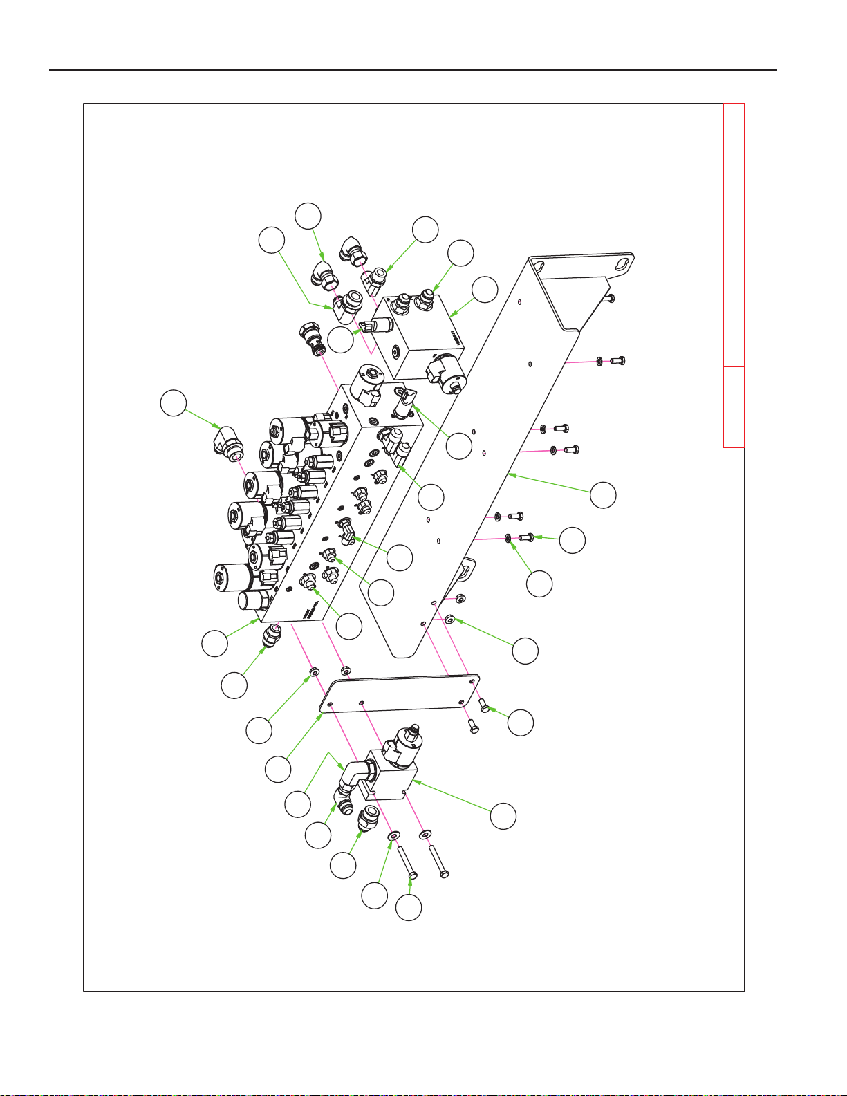
8J55104
8J55405
8J55506
7
25-40' Renegade Hyd Block
5/22/2019
10
5
17
1
10
7
6
19
16
11
15
17
15
18
2
10
7
9
5
13
14
9
8
4
3
12
25-40'
RENEGADE
14
PARTS
3-29
Page 57
PARTS
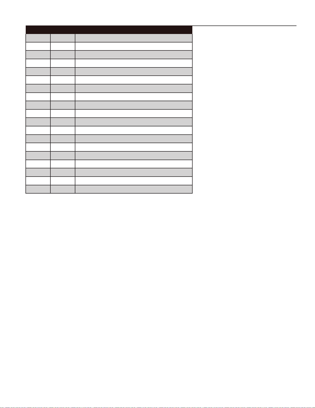
ITEM PN DESCRIPTION
1 8B2535 DEPTH CNTRL VLV MNT
2 8B2538 HYD VLV BLOCK MOUNT
3 8J5500 9/16”-18 ORB X #6 JIC(M) STR
4 8J5510 3/4”-16 ORB X #6 JIC(M) STR
5 8J5540 7/8”-14 ORB X #10 JIC(M) STR
6 8J5550 1-1/16” - 12ORBX#10JIC(M)STR
7 8J5710 #10 JIC(F-SW)X#10 JIC(M)90*ADP
8 8J6000 9/16”-18 ORB X #6 JIC(M) 90°ADP
9 8J6030 7/8”-14 ORB X #10 JIC(M)90°ADP
10 8J6050 1-1/16” - 12ORBX#10JIC(M)90*ADP
11 8N7020 POPPET VALVE 2WAY PROPORTIONAL
12 8N7025 AUX VALVE 5 FUNCTION
13 8N7030 ADJ DN PRSSR MNFLD PROPRTIONAL
14 8N7100 TRANSDUCER 0-5000PSI
15 8X0021 BOLT 5/16-18NC X 3/4” GR5 ZDI
16 8X0024 BOLT 5/16-18NC X 2-1/2” GR5 YZ
17 8X0211 NUT 5/16”-18NC SERFLANG GR2 YZ
18 8X0300 LOCKWASHER 5/16” YLW ZNC
19 8X0329 WASHER 5/16”(3/8” ID)FLAT YZ
3-30
Page 58
PARTS
4/16/2019
30' VRT RENEGADE
30' DM Hydraulics.idw
5 6
7 8
Գ
Front
5 6
7 8
Գ
Front
1 2 3 4
1 2 3 4
1 2
3
4
5
6
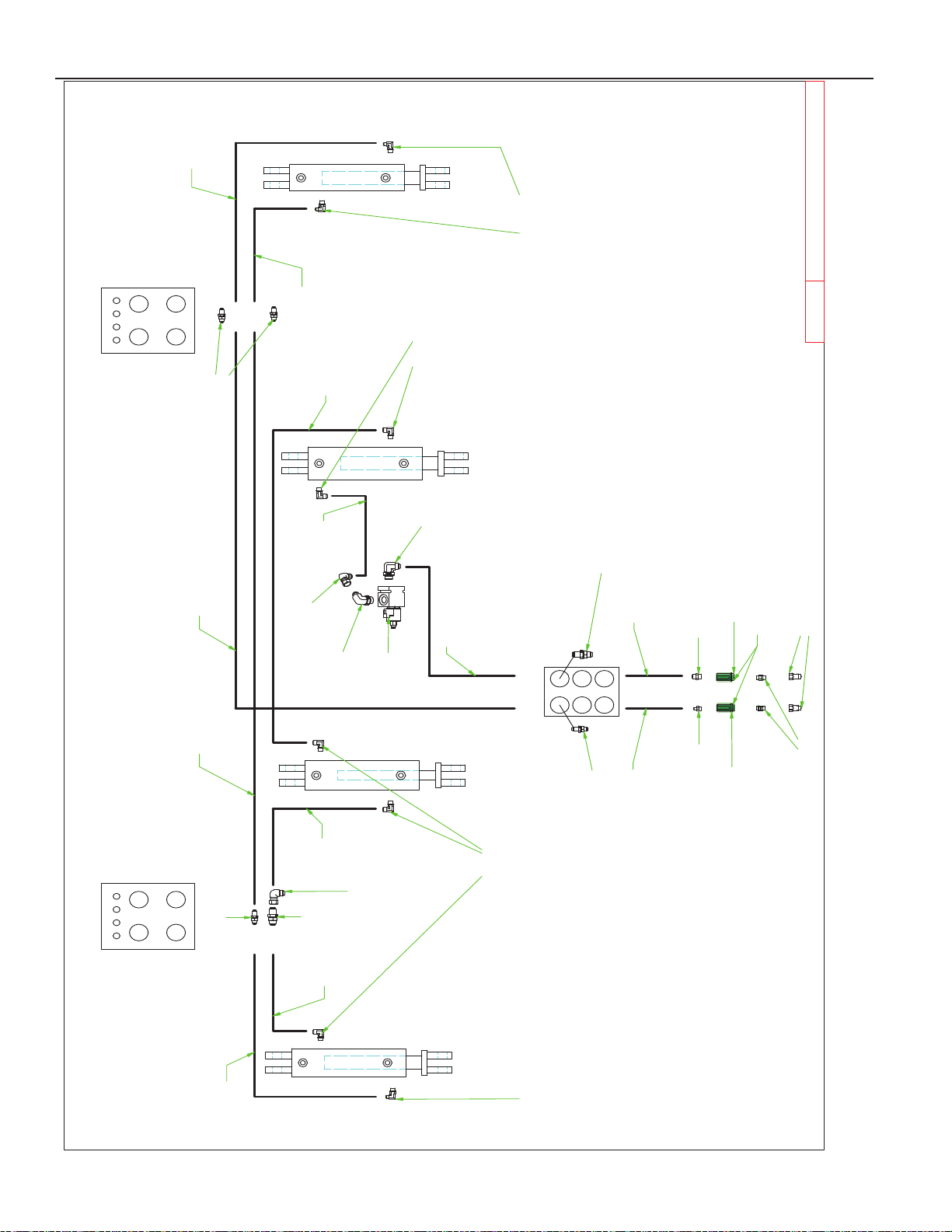
25'-30' MAIN LIFT HYDRAULIC CIRCUIT
8D3212
3/4" ORB TIP ISO
8J5520
3/4" ORB X #10 STR
8J5510
3/4" ORB X #6 JIC(M)
8J6020
3/4"-16ORB X 10 JIC(M) 90
° ADP
8T1045
8T1040B
8T1037
8T1035
8J6010
3/4-16ORB X #6JIC(M) 90° ADP
F
R
O
N
T
8N6200
3/4 X 200"
8N3204
3/8 X 204"
8N6124
3/4 X 124"
8N6060
3/4 X 60"
8N4114
1/2 X 114"
8N4030
1/2 X 30"
8N4114
1/2 X 114"
8N3108
3/8 X 108"
8N3108
3/8 X 108"
8N3108
3/8 X 108"
8N3180
3/8 X 180"
8J6010
3/4-16ORB X #6JIC(M) 90° ADP
8N7020
8J6020
3/4"-16ORB X 10 JIC(M) 90° ADP
8J6050
8J5710
#10 JIC(F-SW)X#10 JIC(M)90*ADP
8J5111
8J5101
Thru 1 Thru 2
Thru 3
Thru 6
8J5101
8J5111
Thru 3
Thru 4
8J5101
8J6050
Positive Grip
Negative Grip
8J5680
3/4"X3/4" UNION
8D3500G
GREEN COLOR HYDRAULIC QD GRIP
8J5710
#10 JIC(F-SW)X#10 JIC(M)90*ADP
8N3096
3/8" X 96"
3-31
Page 59
PARTS
4/16/2019
30' VRT RENEGADE
30' DM Hydraulics.idw
1 2 3 4
5 6
7 8
Գ
Front
1 2 3 4
5 6
7 8
Գ
Front
8B4040
8B4045
8B4045
8B4040
8B4040
8B4045
8B4045
8B4040
Front
Thru 3
Thru 4
Thru 4
Thru 3
Thru 2
Thru 1
Thru 2
Thru 1
8J6010
3/4-16ORB X #6JIC(M) 90° ADP
8J5510
3/4" ORB X #6 JIC(M)
8J6010
3/4-16ORB X #6JIC(M) 90° ADP
8J5700
#6 JIC(F-SW) X #6 JIC(M) 90° ADP
8J5298
#6 JIC(M+M+F-SW) TEE
8J5300
#6 JIC(M) TEE
8J5700
#6 JIC(F-SW) X #6 JIC(M) 90° ADP
8J5300
#6 JIC(M) TEE
8N3084
3/8 X 84"
8N3028
3/8 X 28"
8N3096
3/8 x 96"
8N3084
3/8 X 84"
8N3048
3/8 x 48"
8N3084
3/8 X 84"
8N3070
3/8 x 70"
8N3096
3/8 X 96"
8N3060
3/8 X 60"
8N3028
3/8 X 28"
8N3028
3/8 X 28"
8N3096
3/8 X 96"
8N3084
3/8 X 84"
8N3060
3/8 X 60"
8N3028
3/8 X 28"
8J5510
3/4" ORB X #6 JIC(M)
8N3070
3/8 X 70"
8N3070
3/8 X 70"
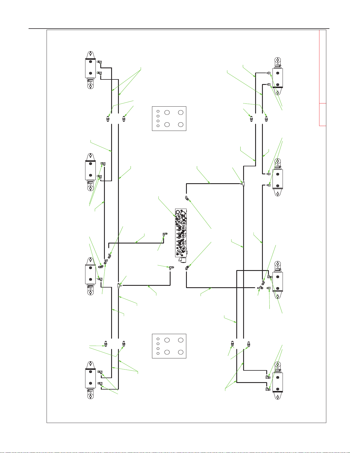
25'-30' GANG ANGLE HYDRAULIC CIRCUIT
8J5298
#6 JIC(M+M+F-SW) TEE
8J5995
Port F
Port E
Port I
Port J
8J5101
8J5101
8J5101
8J5101
8J6000
9/16ORB X #6JIC(M) 90°
8N7025
8J6010
3/4-16ORB X #6JIC(M) 90° ADP
8N3048
3/8 X 48"
8N3060
3/8 X 60"
3-32
Page 60
PARTS
4/16/2019
30' VRT RENEGADE
30' DM Hydraulics.idw
1 2 3 4
5
6
7
8
< < < MACHINE FRONT
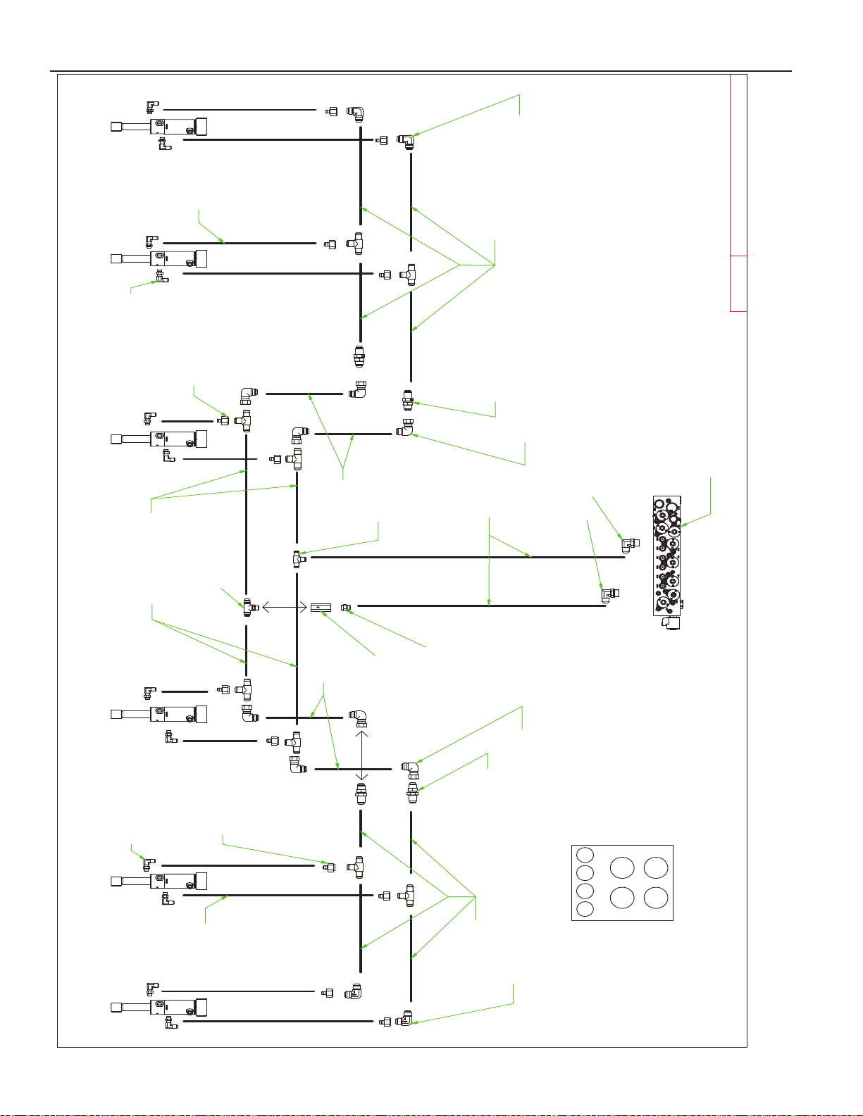
25'-30' BASKET DOWN PRESSURE HYDRAULIC CIRCUIT
SEE NOTE 2
To Port A
To Port B
Notes:
1.) ALL HOSES GOING INTO CYLINDERS ARE THE SAME (3/8" X 18")
2.) 8J7116: RESTRICTOR ARROW MUST POINT INTO TEE
ALL CYLINDERS: 8B2175
8N7025
8J5520
3/4" ORB X #10 STR
8J7116
THRU 5
THRU 6
THRU 8
THRU 7
8J5312
#10(M) X #10(M) X 3/4ORB TEE
(9X)
8J5310
#10(M) TEE
(8X)
8J5710
#10 JIC(F-SW)X#10 JIC(M)90*ADP
(4X)
8J5710
#10 JIC(F-SW)X#10 JIC(M)90*ADP
(2X)
8J5112
#10 JIC(M) X #10 JIC(M) 90
(2X)
8J5112
#10 JIC(M) X #10 JIC(M) 90
8N4084
1/2" X 84"
8N4042
1/2" X 42"
8N4042
1/2" X 42"
(2X) 8J5111
(2X) 8J5111
(6X)
8N3018
3/8" X 18"
(6X)
8N3018
3/8" X 18"
8N4012
1/2" X 12"
8N4012
1/2" X 12"
8N4060
1/2" X 60"
8N4060
1/2" X 60"
8J6030
7/8"X#10(M) 90° ADP
(6X)
8J5200
#10(F)X#6(M) BUSH
(6X)
8J5200
#10(F)X#6(M) BUSH
(6X)
8J6000
9/16 ORB X #6 JIC (M) 90
(6X)
8J6000
9/16 ORB X #6JIC (M) 90
3-33
Page 61
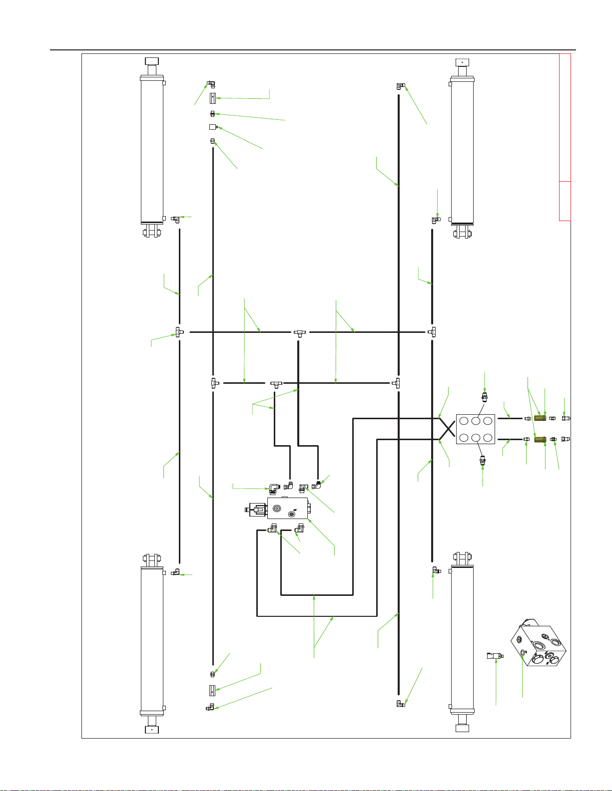
PARTS
4/16/2019
30' VRT RENEGADE
30' DM Hydraulics.idw
1 2
3 4
5 6
F
R
O
N
T
25'-30' WING FOLD/DOWN PRESSURE HYDRAULIC CIRCUIT
PORT "A"
PORT "B"
PORT "P1"
PORT "P2"
8K9640
8K9640
8K9640
8K9640
8N4038
1/2" X 38"
8N4038
1/2" X 38"
8N4016
1/2" X 16"
8N4016
1/2" X 16"
8N4120
1/2" X 120"
THRU 3
THRU 4
8N4065
1/2' X 65"
8N4035
1/2" X 35"
8N4085
1/2" X 85"
8N4042
1/2" X 42"
8N4042
1/2" X 42"
8N4016
1/2" X 16"
8N4016
1/2" X 16"
8J5520
3/4" ORB X #10 STR
8J7040
THERMAL RELIEF
8J5690
3/4-16X3/4-16 ORB M-SW 90° UNION
8J5680
3/4"X3/4" UNION
8J6020
3/4"-16ORB X 10 JIC(M) 90° ADP
8J5680
3/4"X3/4" UNION
8J5690
3/4-16X3/4-16 ORB M-SW 90° UNION
8J6020
3/4"-16ORB X 10 JIC(M) 90° ADP
8J6020
3/4"-16ORB X 10 JIC(M) 90° ADP
8J6020
3/4"-16ORB X 10 JIC(M) 90° ADP
(6X)
8J5310
#10(M) TEE
8N4198
1/2" X 198"
8N4198
1/2" X 198"
PORT "GP"
8J5520
3/4" ORB X #10 STR
8D3212
3/4" ORB TIP ISO
8J7116
SEE NOTES
8J7116
NOTES:
1. 8J7116: RESTRICTOR ARROW DIRECTION MUST BE
POINTED INTO THE CYLINDER
8J5111
8J5111
8N7030
8N7100
SEE NOTES
(2X)
8J5710
#10 JIC(F-SW) X #10 JIC(M) 90° ADP
8J6030
7/8"X#10(M) 90° ADP
8J6030
7/8"X#10(M) 90° ADP
8J6050
1-1/16"-12ORB X #10JIC(M)90*AD
Positive Grip
8D3500Y
YELLOW COLOR HYDRAULIC QD GRIP
Negative Grip
8J5680
3/4"X3/4" UNION
3-34
Page 62
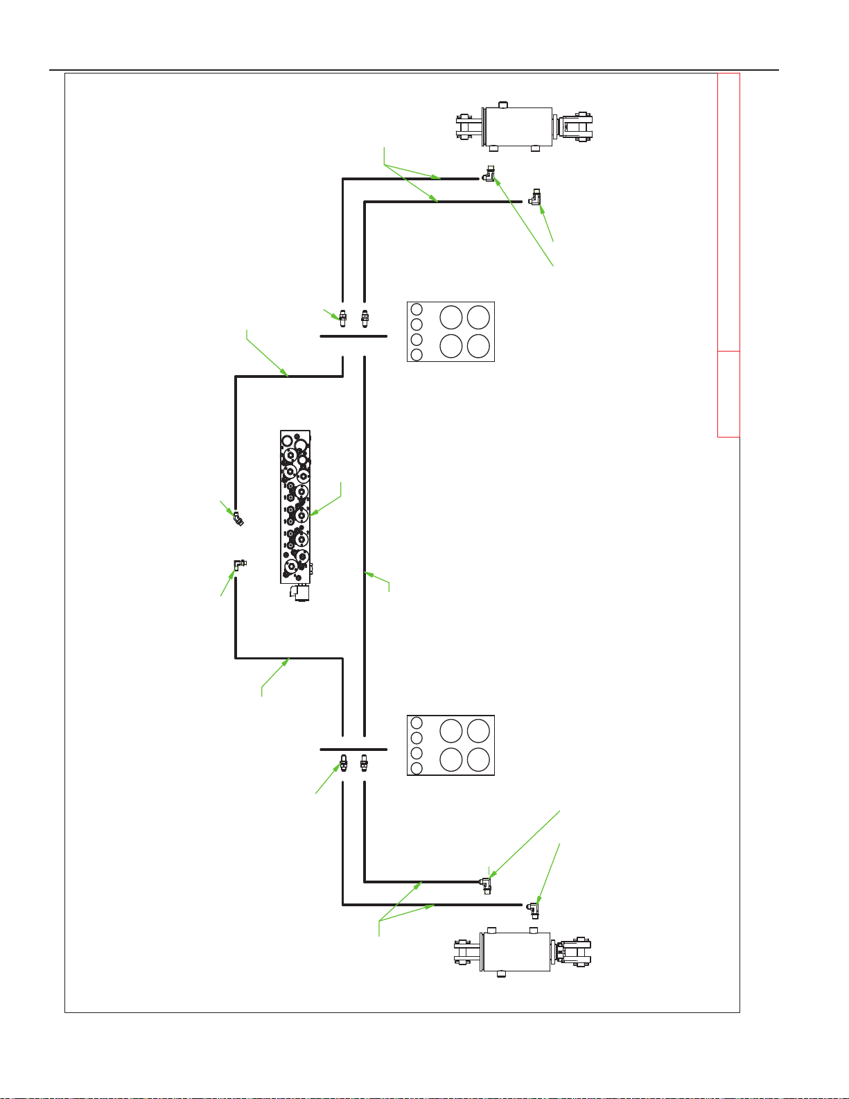
PARTS
4/16/2019
30' VRT RENEGADE
30' DM Hydraulics.idw
8
7
6
5
4321
5
6
1
7
2 3 4
8
25'-30' GAUGE WHEEL HYDRAULIC CIRCUIT
MACHINE FRONT
MACHINE FRONT
THRU 2
THRU 1
THRU 1
THRU 2
PORT "D"
PORT "C"
8J5101
8J5101
8J6010
3/4-16ORB X #6JIC(M) 90° ADP
8J5995
8J6000
9/16ORB X #6JIC(M) 90°
8N3124
3/8" X 124"
8N3096
3/8" X 96"
8N3096
3/8" X 96"
8N3124
3/8" X 124"
8N7025
8B4040
8B4540
8N3096
3/8" X 96"
8J6010
3/4-16ORB X #6JIC(M) 90° ADP
3-35
Page 63
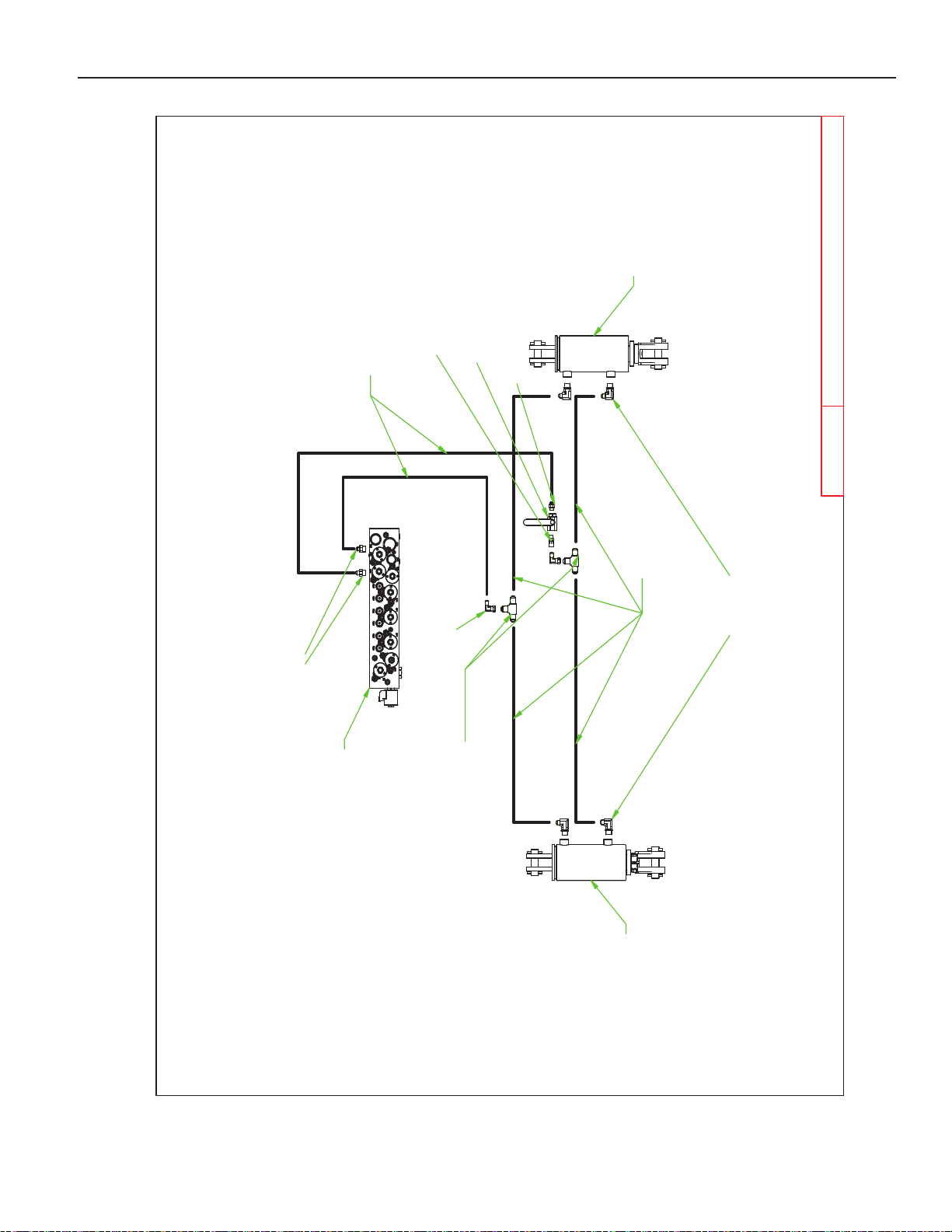
PARTS
4/16/2019
30' VRT RENEGADE
30' DM Hydraulics.idw
25'-30' HITCH HYDRAULIC CIRCUIT
PORT "G"
PORT "H"
8J5700
#6 JIC(F-SW) X #6 JIC(M) 90° ADP
8J6010
3/4-16ORB X #6JIC(M) 90° ADP
8N3035
3/8" X 35"
8N3096
3/8" X 96"
8J5510
3/4" ORB X #6 JIC(M)
8N7025
8T2040
8T2040
(2X)
8J5300
#6 JIC (M) TEE
8J7000
VALVE 9/16ORB
8J5500
9/16" X #6 JIC(M)
8J5600
9/16" X #6 JIC (F-SW)
3-36
Page 64
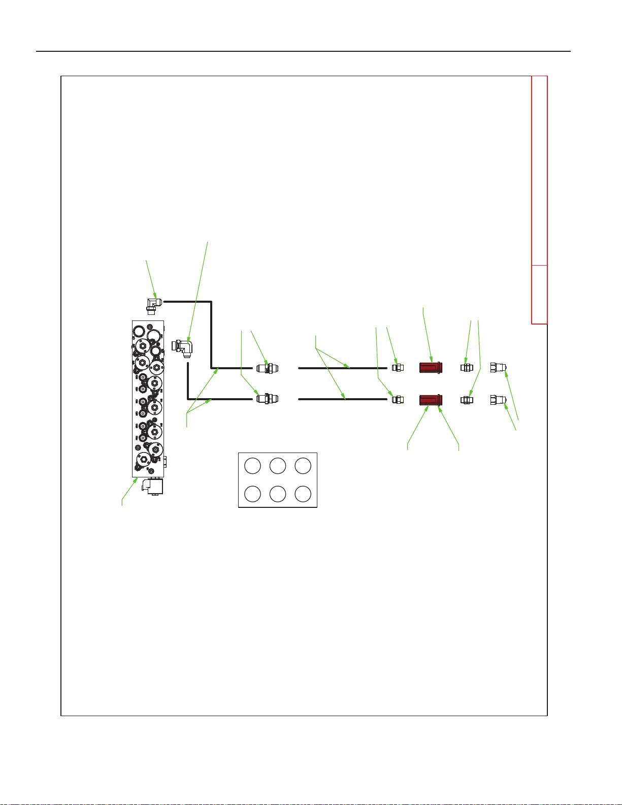
PARTS
4/16/2019
30' VRT RENEGADE
30' DM Hydraulics.idw
FRONT
1 2
3 4
5 6
8N7025
25'-30' HYDRAULIC BLOCK POWER CIRCUIT
8J6030
7/8"X#10(M) 90° ADP
8J6050
8N6124
3/4" X 124"
8J5111
8J5520
3/4" ORB X #10 STR
8J5680
3/4"X3/4" UNION
8D3212
3/4" ORB TIP ISO
8N6200
3/4" X 200"
Port "P"
Port "T"
Thru 5 Thru 6
8D3500R
RED HYDRAULIC QD GRIP
Negative Grip
Positive Grip
3-37
Page 65
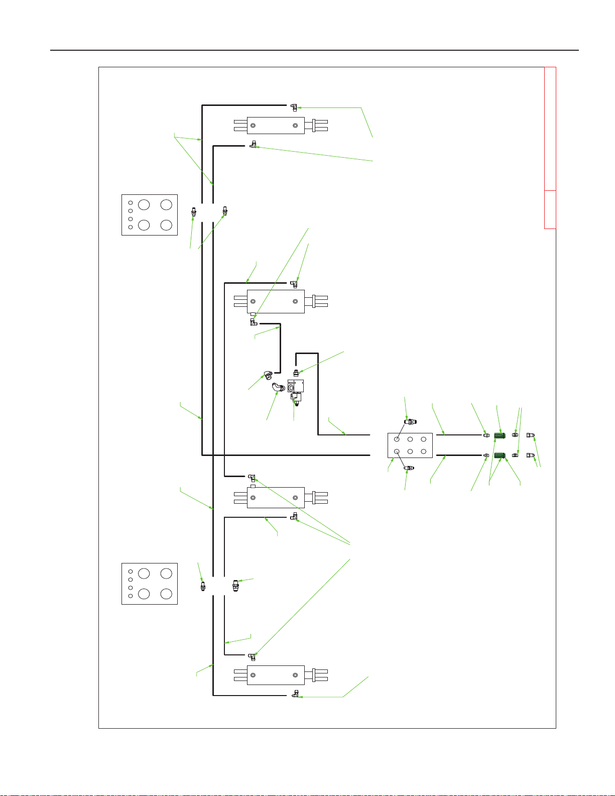
PARTS
10/23/2018
40' VRT RENEGADE
40' DM Hydraulics.idw
5 6
7 8
Գ
Front
5 6
7 8
Գ
Front
1 2 3 4
1 2 3 4
1 2
3 4
5 6
35'-40' MAIN LIFT HYDRAULIC CIRCUIT
8D3212
3/4" ORB TIP ISO
8J5520
3/4" ORB X #10 STR
8J5510
3/4" ORB X #6 JIC(M)
8J6020
3/4"-16ORB X 10 JIC(M) 90
° ADP
8T1060A
8T1055
8T1050
8T1045
8J6010
3/4-16ORB X #6JIC(M) 90° ADP
Front
8N6235
3/4 X 235"
8N3228
3/8 X 228"
8N6124
3/4 X 124"
8N6060
3/4 X 60"
8N4120
1/2 X 120"
8N4030
1/2 X 30"
8N4120
1/2 X 120"
8N3124
3/8 X 124"
8N3180
3/8 X 180"
8N3124
3/8 X 124"
8N3204
3/8 X 204"
8J6010
3/4-16ORB X #6JIC(M) 90° ADP
8N7020
8J6020
3/4"-16ORB X 10 JIC(M) 90° ADP
8J6050
8J5710
#10 JIC(F-SW)X#10 JIC(M)90*ADP
8J5550
1-1/16" - 12ORBX#10JIC(M)STR
8J5111
8J5101
Thru 1 Thru 2
Thru 3
Thru 6
8J5101
8J5111
Thru 3
Thru 4
8J5101
8J5680
3/4"X3/4" UNION
8D3500G
GREEN COLOR HYDRAULIC QD GRIP
Negative Grip
Positive Grip
3-38
Page 66
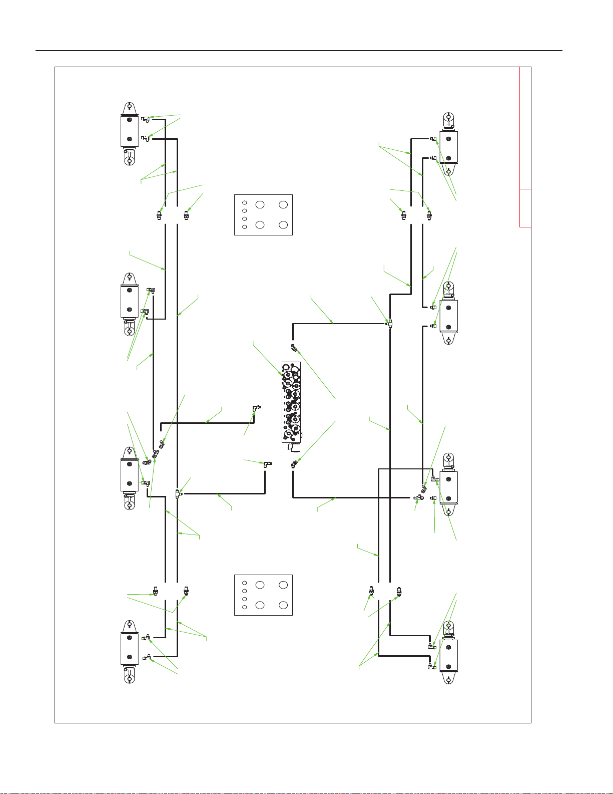
PARTS
10/23/2018
40' VRT RENEGADE
40' DM Hydraulics.idw
1 2 3 4
5 6
7 8
Գ
Front
1 2 3 4
5 6
7 8
Գ
Front
8B4040
8B4540
8B4540
8B4040
8B4040
8B4540
8B4540
8B4040
Front
Thru 3
Thru 4
Thru 4
Thru 3
Thru 2
Thru 1
Thru 2
Thru 1
8J6010
3/4-16ORB X #6JIC(M) 90° ADP
8J5510
3/4" ORB X #6 JIC(M)
8J6010
3/4-16ORB X #6JIC(M) 90° ADP
8J5700
#6 JIC(F-SW) X #6 JIC(M) 90° ADP
8J5298
#6 JIC(M+M+F-SW) TEE
8J5300
#6 JIC(M) TEE
8J5700
#6 JIC(F-SW) X #6 JIC(M) 90° ADP
8J5300
#6 JIC(M) TEE
8N3150
3/8 X 150"
8N3060
3/8 X 60"
8N3150
3/8 x 150"
8N3124
3/8 X 124"
8N3096
3/8 x 96"
8N3084
3/8 X 84"
8N3070
3/8 x 70"
8N3108
3/8 X 108"
8N3150
3/8 X 150"
8N3028
3/8 X 28"
8N3060
3/8 X 60"
8N3135
3/8 X 135"
8N3124
3/8 X 124"
8N3070
3/8 X 70"
8N3035
3/8 X 35"
8J5510
3/4" ORB X #6 JIC(M)
8N3108
3/8 X 108"
8N3084
3/8 X 84"
35'-40' BLADE ANGLE HYDRAULIC CIRCUIT
8J5298
#6 JIC(M+M+F-SW) TEE
8J5995
Port F
Port E
Port I
Port J
8J5101
8J5101
8J5101
8J5101
8J6000
9/16ORB X #6JIC(M) 90°
8N7025
8J6010
3/4-16ORB X #6JIC(M) 90° ADP
8J6010
3/4-16ORB X #6JIC(M) 90° ADP
3-39
Page 67
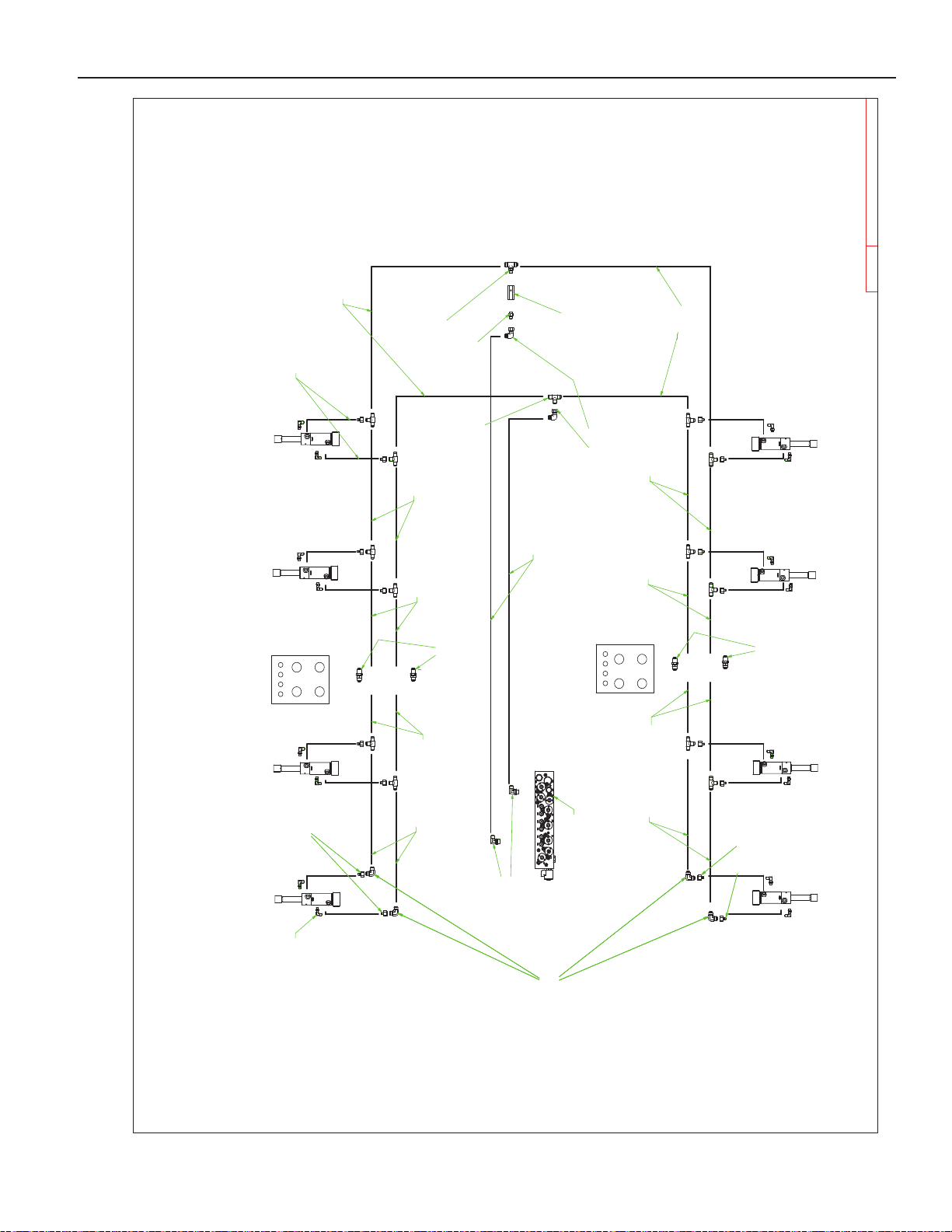
PARTS
10/23/2018
40' VRT RENEGADE
40' DM Hydraulics.idw
1 2 3 4
5 6
7 8
Գ
Front
1 2 3 4
5 6
7 8
Գ
Front
35' BASKET DOWN PRESSURE HYDRAULIC CIRCUIT
8J5312
#10(M) X #10(M) X 3/4ORB TEE
8J7116
RESTRICTOR ARROW
POINTING INTO TEE
8J6030
7/8"X#10(M) 90° ADP
To Port A
To Port B
8J5520
3/4" ORB X #10 STR
8J5310
#10(M) TEE
8J5710
#10 JIC(F-SW)X#10 JIC(M)90*ADP
Thru 5
Thru 6
Thru 6
Thru 5
8N4084
1/2 x 84"
8N4042
1/2 x 42"
8N4026
1/2 x 26"
8N4020
1/2 X 20"
8N4060
1/2 x 60"
8N4042
1/2 X 42"
8N4042
1/2 X 42"
8N4026
1/2 X 26"
8N4020
1/2 X 20"
8N4060
1/2 X 60"
8N4042
1/2 X 42"
8J5111
8J5111
Note: All fittings and hose lengths braching off
of the main line going to the cylinders are the
same unless otherwise noted.
8B2175
8B2175
8B2175
8B2175
8B2175
8B2175
8B2175
8B2175
8N7025
8J5112
#10 JIC(M) X #10 JIC(M) 90°
8J5200
#10(F)X#6(M) BUSH
8J5112
#10 JIC(M) X #10 JIC(M) 90°
8J5200
#10(F)X#6(M) BUSH
8J5200
#10(F)X#6(M) BUSH
8J5112
#10 JIC(M) X #10 JIC(M) 90°
8J5200
#10(F)X#6(M) BUSH
8J5112
#10 JIC(M) X #10 JIC(M) 90°
(16X)
8J6000
9/16 ORB X #6JIC (M) 90
(16X)
8N3018
3/8 X 18"
3-40
Page 68
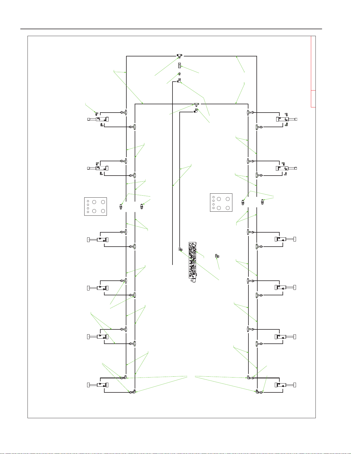
PARTS
10/23/2018
40' VRT RENEGADE
40' DM Hydraulics.idw
1 2 3 4
5 6
7 8
Գ
Front
1 2 3 4
5 6
7 8
Գ
Front
40' BASKET DOWN PRESSURE HYDRAULIC CIRCUIT
8J5112
#10 JIC(M) X #10 JIC(M) 90°
8N4020
1/2 X 20"
8N4048
1/2 X 48"
8J5200
#10(F)X#6(M) BUSH
8J5312
#10(M) X #10(M) X 3/4ORB TEE
8J7116
RESTRICTOR ARROW
POINTING INTO TEE
8J6030
7/8"X#10(M) 90° ADP
To Port A
To Port B
8J5520
3/4" ORB X #10 STR
8J5310
#10(M) TEE
8J5710
#10 JIC(F-SW)X#10 JIC(M)90*ADP
Thru 5
Thru 6
Thru 6
Thru 5
8N4084
1/2 x 84"
8N4042
1/2 x 42"
8N4026
1/2 x 26"
8N4020
1/2 X 20"
8N4060
1/2 x 60"
8N4020
1/2 X 20"
8J5200
#10(F)X#6(M) BUSH
8N4042
1/2 X 42"
8N4026
1/2 X 26"
8N4020
1/2 X 20"
8N4060
1/2 X 60"
8N4020
1/2 X 20"
8N4048
1/2 X 48"
8N4020
1/2 X 20"
8J5111
8J5111
Note: All fittings and hose lengths braching off
of the main line going to the cylinders are the
same unless otherwise noted.
8J5310
#10(M) TEE
8N3018
3/8 X 18"
8B1750
8B1750
8B1750
8B2175
8B2175
8B2175
8B21758B1750
8B1750
8B1750
8B1750
8B1750
8N7025
(8X)
8J6000
9/16 ORB X #6JIC (M) 90
3-41
Page 69
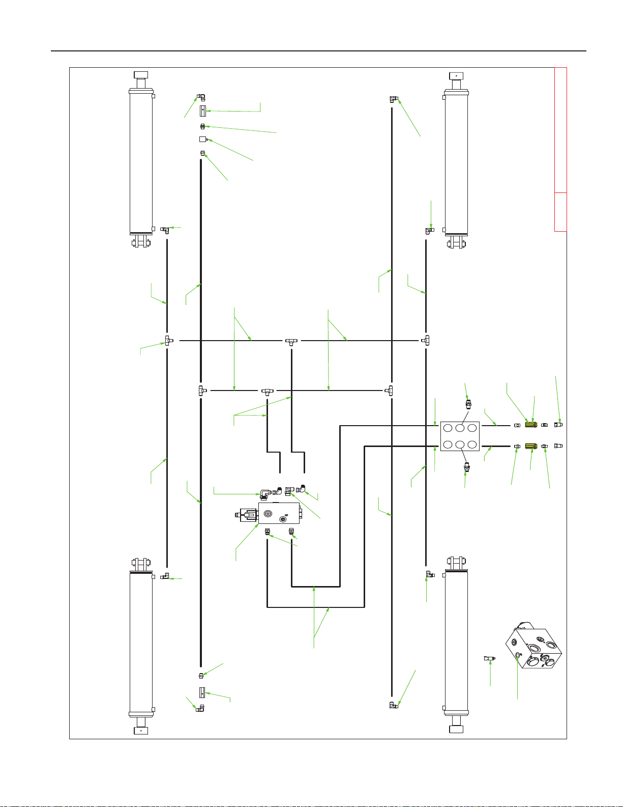
PARTS
10/23/2018
40' VRT RENEGADE
40' DM Hydraulics.idw
1 2
3 4
5 6
F
R
O
N
T
35'-40' WING FOLD/DOWN PRESSURE HYDRAULIC CIRCUIT
PORT "A"
PORT "B"
PORT "P1"
PORT "P2"
8K9650
8K9650
8K9650
8K9650
8N4084
1/2" X 84"
8N4048
1/2" X 48"
8N4048
1/2" X 48"
8N4016
1/2" X 16"
8N4114
1/2" X 114"
THRU 3
THRU 4
8N4060
1/2' X 60"
8N4035
1/2" X 35"
8N4060
1/2" X 60"
8N4060
1/2" X 60"
8N4084
1/2" X 84"
8N4016
1/2" X 16"
8N4048
1/2" X 48"
8J5520
3/4" ORB X #10 STR
8J7040
THERMAL RELIEF
8J5690
3/4-16X3/4-16 ORB M-SW 90° UNION
8J5680
3/4"X3/4" UNION
8J6020
3/4"-16ORB X 10 JIC(M) 90° ADP
8J5690
3/4-16X3/4-16 ORB M-SW 90° UNION
8J6020
3/4"-16ORB X 10 JIC(M) 90° ADP
8J6020
3/4"-16ORB X 10 JIC(M) 90° ADP
8J6020
3/4"-16ORB X 10 JIC(M) 90° ADP
(6X)
8J5310
#10(M) TEE
(2X)
8J5710
#10 JIC(F-SW) X #10 JIC(M) 90° ADP
8N4228
1/2" X 228"
8N4228
1/2" X 228"
8J5540
7/8" ORB X #10 STR
PORT "GP"
8J5520
3/4" ORB X #10 STR
8D3212
3/4" ORB TIP ISO
8J7116
SEE NOTES
8J7116
NOTES:
1. 8J7116: RESTRICTOR ARROW DIRECTION MUST BE
POINTED INTO THE CYLINDER
8J5111
8J5111
8N7030
8N7100
SEE NOTES
8J5680
3/4"X3/4" UNION
8D3500Y
YELLOW COLOR HYDRAULIC QD GRIP
Positive Grip
Negative Grip
8J6050
1-1/16"-12ORB X #10JIC(M)90*AD
8J6030
7/8"X#10(M) 90° ADP
8J5520
3/4" ORB X #10 STR
3-42
Page 70
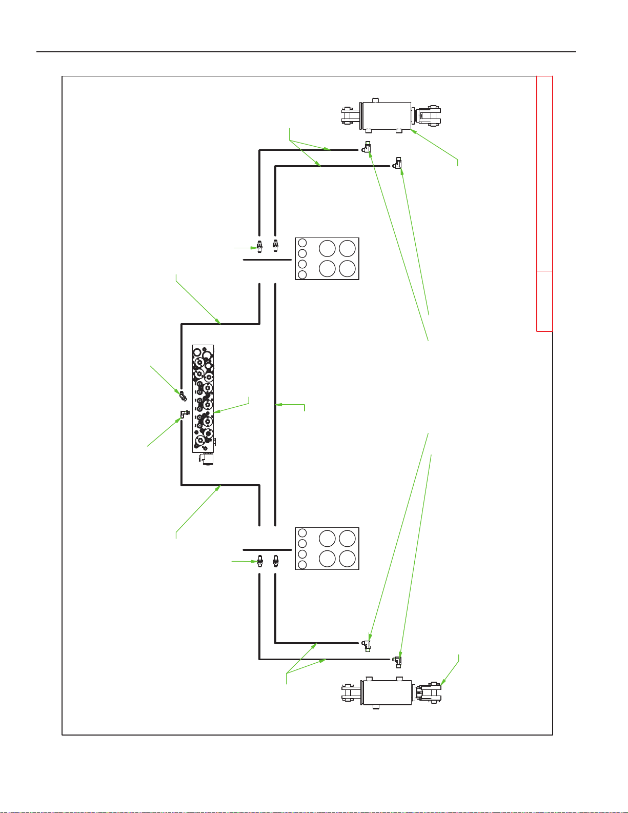
PARTS
10/23/2018
40' VRT RENEGADE
40' DM Hydraulics.idw
87
6
5
4321
5
6
1
7
2 3 4
8
35'-40' GAUGE WHEEL HYDRAULIC CIRCUIT
MACHINE FRONT
MACHINE FRONT
THRU 2
THRU 1
THRU 1
THRU 2
PORT "D"
PORT "C"
8J5101
8J5101
8J6010
3/4-16ORB X #6JIC(M) 90° ADP
8J5995
8J6000
9/16ORB X #6JIC(M) 90°
8B4540
8N3124
3/8" X 124"
8N3180
3/8" X 180"
8N3136
3/8" X 136"
8N3156
3/8" X 156"
8N3124
3/8" X 124"
8N7025
8B4040
3-43
Page 71
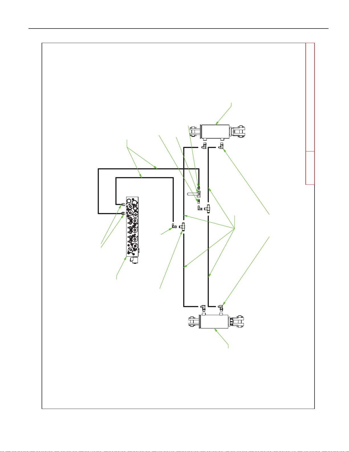
PARTS
10/23/2018
40' VRT RENEGADE
40' DM Hydraulics.idw
35'-40' HITCH HYDRAULIC CIRCUIT
PORT "G"
PORT "H"
8J5700
#6 JIC(F-SW) X #6 JIC(M) 90° ADP
8J5310
#10(M) TEE
8J6010
3/4-16ORB X #6JIC(M) 90° ADP
8N3035
3/8" X 35"
8N3096
3/8" X 96"
8J5510
3/4" ORB X #6 JIC(M)
8N7025
8T2040
8T2040
8J5600
9/16" X #6 JIC (F-SW)
8J7000
VALVE 9/16ORB
8J5500
9/16" X #6 JIC(M)
3-44
Page 72
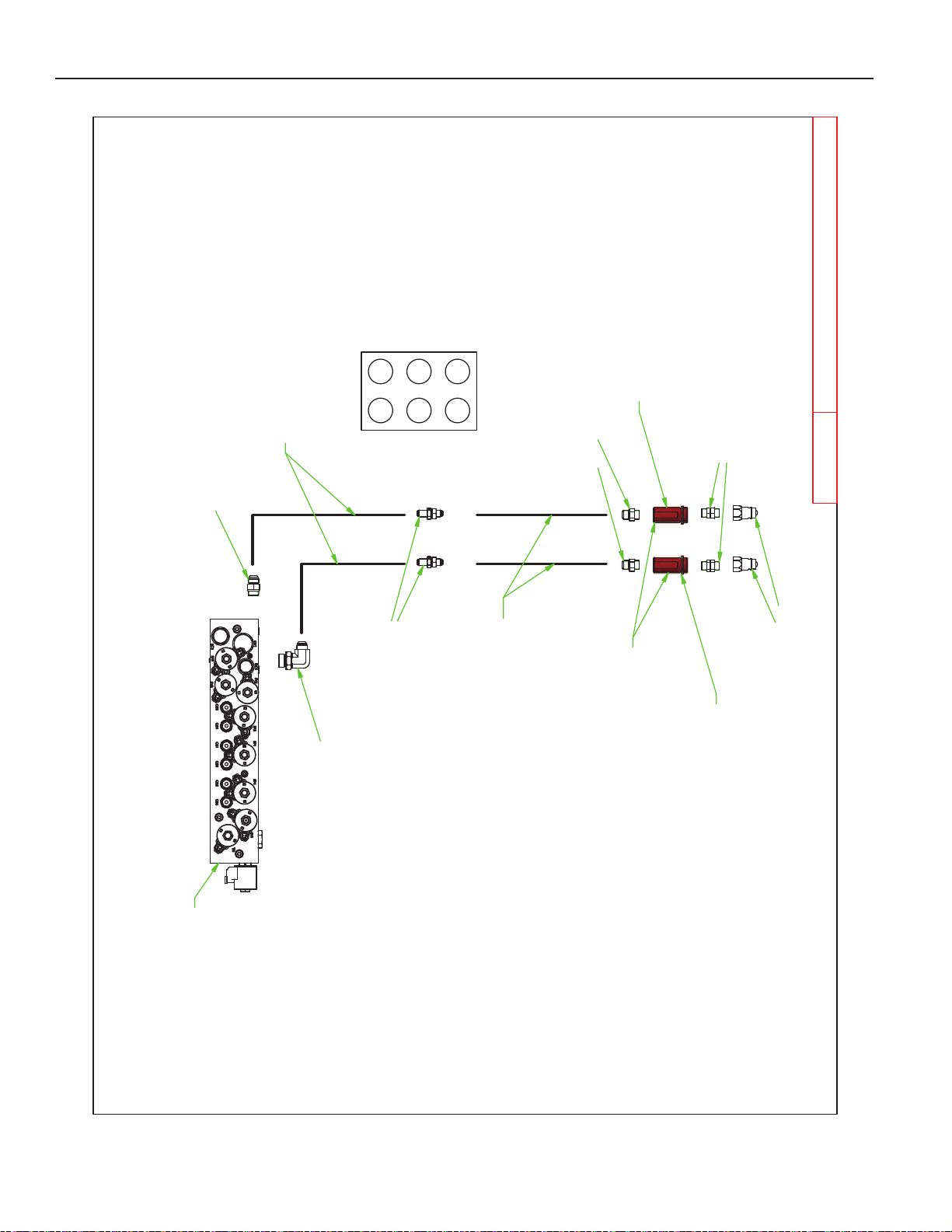
PARTS
10/23/2018
40' VRT RENEGADE
40' DM Hydraulics.idw
1 2
3 4
5 6
Front
8N7025
35'-40' AUX BLOCK CIRCUIT
8N6124
3/4" X 124"
8N6235
3/4” X 235”
Thru 5 Thru 6
8J5520
3/4" ORB X #10 STR
8J5680
3/4"X3/4" UNION
8D3212
3/4" ORB TIP ISO
8D3500R
RED COLOR HYDRAULIC QD GRIP
8J5101
8J6050
8J5540
7/8" ORB X #10 STR
Negative Grip
Positive Grip
3-45
Page 73

PARTS
3-46
Page 74
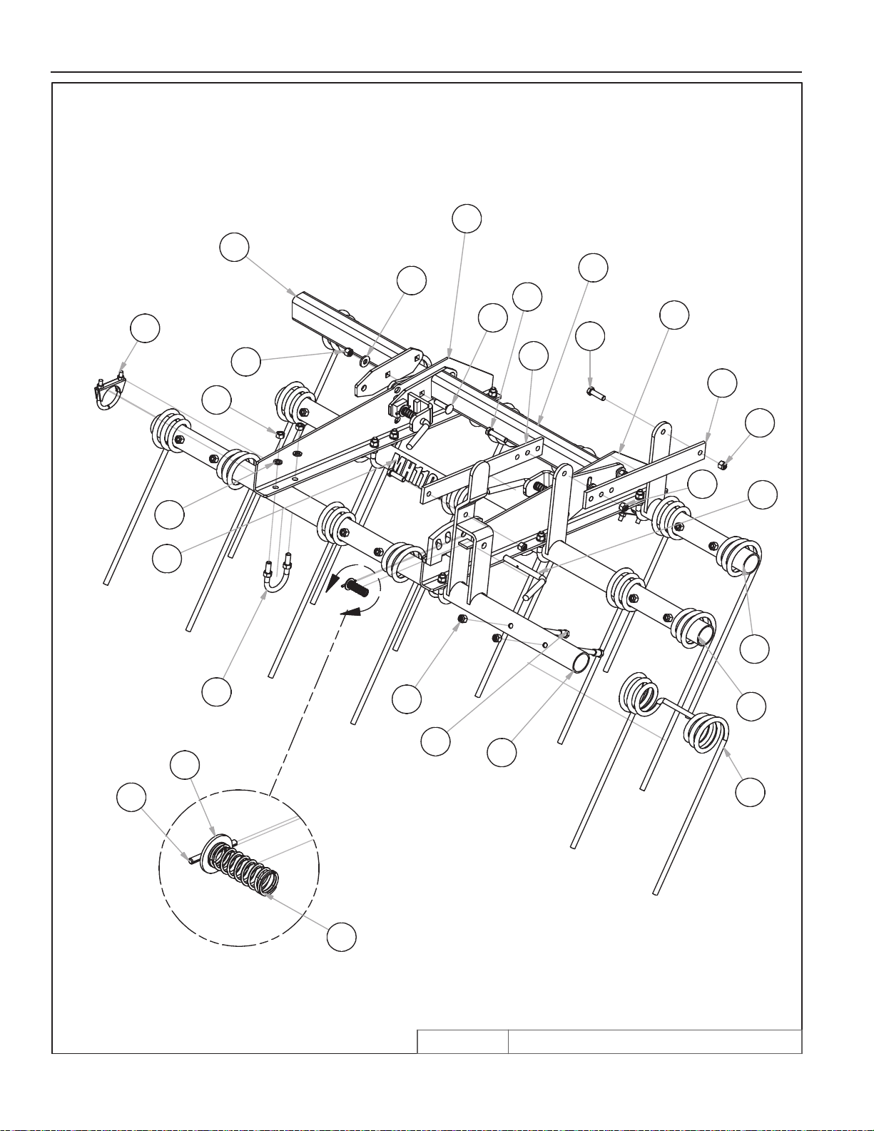
DETAIL A
6' 3BR M104
6/5/2015
8HD5361Q.iam/
A
2
13
19
22
15
11
19
6
7
8
1
19
17
5
18
14
11
24
3
16
19
9
10
12
20
23
21
4
PARTS
3-47
Page 75
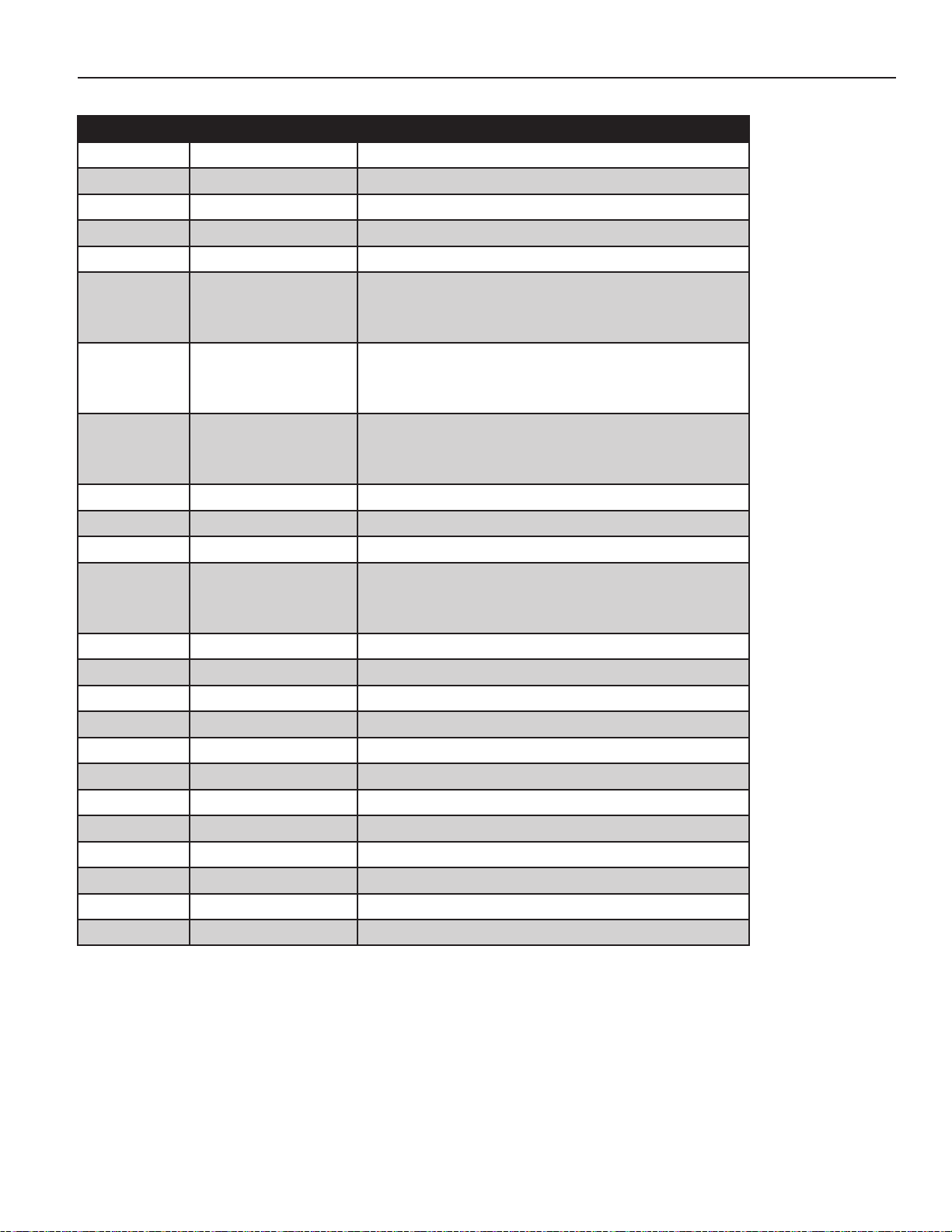
PARTS
VRT MOUNTED HARROWS
ITEM PART NUMBER DESCRIPTION
1 8H1180S HARROW TOOTH 1/2 X 20” M104/SH
2 8HD0080 PIPE CLAMP 2-1/2”ID PLATED ZDI
3 8HD0150 PIN
4 8HD0160 COMPRESSION SPRING
5 8HD0200 U-BOLT 1/2” X 2-3/8” X 3-9/16” RND
6 8HD5052
8HD5072
8HD5082
7 8HD5054
8HD5074
8HD5084
8 8HD5056Q
8HD5076Q
8HD5086Q
9 8HD5111 SIDE PLT 1/4”3BR QADJ LEFT
10 8HD5112 SIDE PLT 1/4”3BR QADJ RGHT
11 8HD5115 ADJUSTABLE CONNECTING BAR
12 8HD5141
8HD5151
8HD5161
13 8HD5181 EXT BRKT QADJ 2ND ARM 15”
14 8X0065 CRG 1/2-13NC X 2” GR5 YZ
15 8X0066 BOLT 1/2-13NC X 1-3/4” GR5 YZ
16 8X0067 BOLT 1/2-13NC X 2-1/4” GR5 YZ
17 8X0079 BOLT 1/2-13X4.12”SHOULDR GR2 YZ
18 8X0240 NUT 1/2”-13NC HEX GR2 YZ
19 8X0242 NUT 1/2”-13NC NY-LOCK GR2 YZ
20 8X0303 LOCKWASHER 1/2” YLW ZNC
21 8X0323 WASHER 5/8” SAE FLAT YZ
22 8X0330 WASHER 17/32”ID X 1.25”OD YZ
23 8X0520 ROLL PIN 3/16 X 2” ZINC CLEAR
24 8Z0114 MH1104 DECAL
1ST PIPE W/LVR 6’ 3OR4BR
1ST PIPE W/LVR 8’ 104/6 3OR4BR
1ST PIPE W/LVR10’ 104/6 3OR4BR
2ND PIPE W/LVR 6’ 3OR4BR
2ND PIPE W/LVR 8’ 104/6 3OR4BR
2ND PIPE W/LVR10’ 104/6 3OR4BR
3RD PIPE/LVR6’ 3BR104/6QADJ
3RD PIPE/LVR8’ 3BR104/6QADJ
3RD PIPE/LVR10’ 3BR104/6QADJ00
CROSS TUBE W/FLATS 6’ QADJ
CROSS TUBE W/FLATS 8’ QADJ
CROSS TUBE W/FLATS 10’ QADJ13-
3-48
Page 76
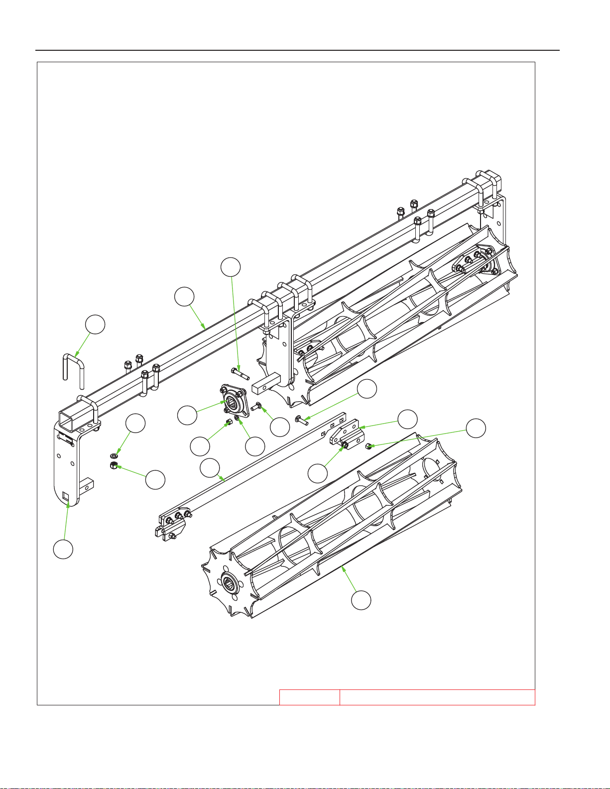
RLLNG BSKT ASSY 8FT6/11/2019
8H2718B.iam/
6
7
1
15
13
5
11 14
8
10
9
3
12
11
2
4
PARTS
3-49
Page 77
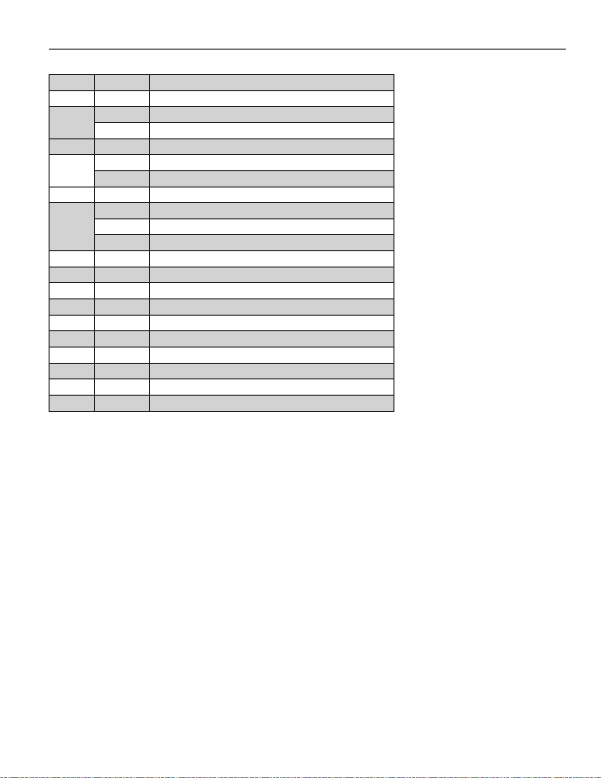
PARTS
ROLLING BASKETS
ITEM PN DESCRIPTION
1 8H2601B RLLNG BSKT ENDPLATE 4SCRPR
2 8H2634 RLLNG BSKT 4’ REEL ONLY
8H2636 RLLNG BSKT 6’ REEL ONLY
3 8H2660B RLLING BSKT SCRAPR MNT
4 8H2664 4’ BSKT SCRAPER (40.5”)
8H2666 6’ BSKT SCRAPER (63.5”)
5 8H2703 BEARING 1-1/4” SQ FLNG4BLT
6 8H2706 TUBE SQ 3 X 4T- 70” BSKT MNT
8H2708 TUBE SQ 3 X 4T- 94” BSKT MNT
8H2710 TUBE SQ 3 X 4T- 118” BSKT MNT
7 8S0358 U-BOLT 5/8 X 3-1/16 X 4-1/2” SQ.
8 8X0064 CRG 1/2-13NC X 1-1/2” GR5 YZ
9 8X0065 CRG 1/2-13NC X 2” GR5 ZDI
10 8X0069 BOLT 1/2-13NC X 3” GR5 ZDI
11 8X0242 NUT 1/2”-13NC NY-LOCK GR2 YZ
12 8X0244 NUT 1/2”-13NC FLANG TOP LOCK Z
13 8X0253 NUT 5/8”-11NC NY-LOCK GR2 YZ
14 8X0303 LOCKWASHER 1/2” YLW ZNC
15 8X0304 LOCKWASHER 5/8” YLW ZNC
16 8Z0046 PATENT PENDING DECAL
3-50
Page 78
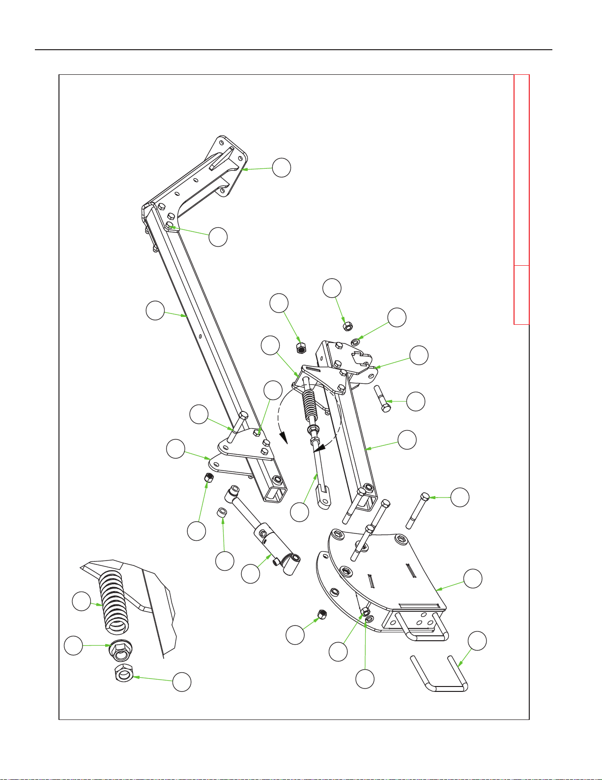
DETAIL A
8B21751
8C17552
8H12903
8H12954
8H20055
8H30006
7
8H30219
8H303010
8H303312
8X009513
8X011314
8X011615
8X011816
8X026017
8X026118
8X026919
8X027120
8X027421
8X030622
A
ARM ASSY -
32"HRRW/57"BSKT
6/26/2019
8H3100.iam/
20
1
18
14
17
22
16
15
2
22
17
18
19
21
6
5
3
9
7
12
11
10
13
13
8
4
PARTS
3-51
Page 79
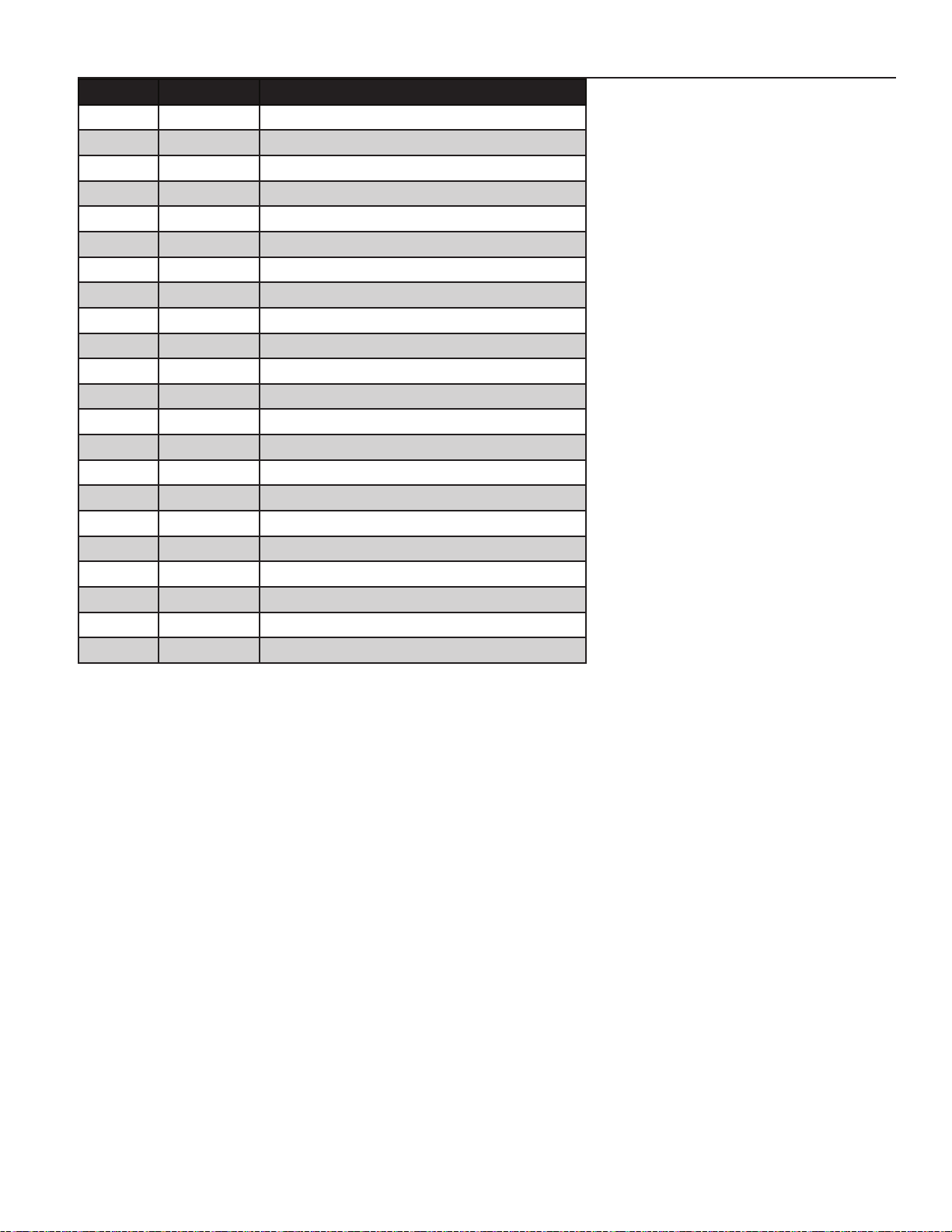
PARTS
ITEM PN DESCRIPTION
1 8B2175 HYD CYL 2.0 X 1.75” HYD BSKT
2 8C1755 U-BOLT 3/4 X 6-1/16 X 6” SQ
3 8H1290 BOLT-SPRINGROD 7/8” X 29”
4 8H1295 SPRING-COMP - 1.71”ODX7”X.262”
5 8H2005 CYLINDER SPACER
6 8H3000 MNT HEAD HRRW/HYD BSKT
7 8H3010 ARM, HRRW- 32”
8 8H3020 ARM, BSKT- 57”
9 8H3021 CYL ATTCH-HYD BSKT ARM
10 8H3030 RLLNG BSKT ATTCH ARM
11 8H3032 HRRW ATTCH CLAMP
12 8H3033 HRRW SPRINGROD ATTCH
13 8X0095 BOLT 5/8-11NC X 5” GR5 YZ
14 8X0113 BOLT 3/4-10NC X 5” GR5 YZ
15 8X0116 BOLT 3/4-10NC X 6” GR5 YZ
16 8X0118 BOLT 3/4-10NC X 4” GR5 ZDI
17 8X0260 NUT 3/4”-10NC HEX GR2 YZ
18 8X0261 NUT 3/4”-10NC NY-LOCK GR2 YZ
19 8X0269 NUT 7/8”-9NC JAM GR2 ZDI
20 8X0271 NUT 7/8”-9NC NY-LOCK GR2 YZ
21 8X0274 NUT 7/8”-9NC SERFLANG GR2 YZ
22 8X0306 LOCKWASHER 3/4” YLW ZNC
3-52
Page 80
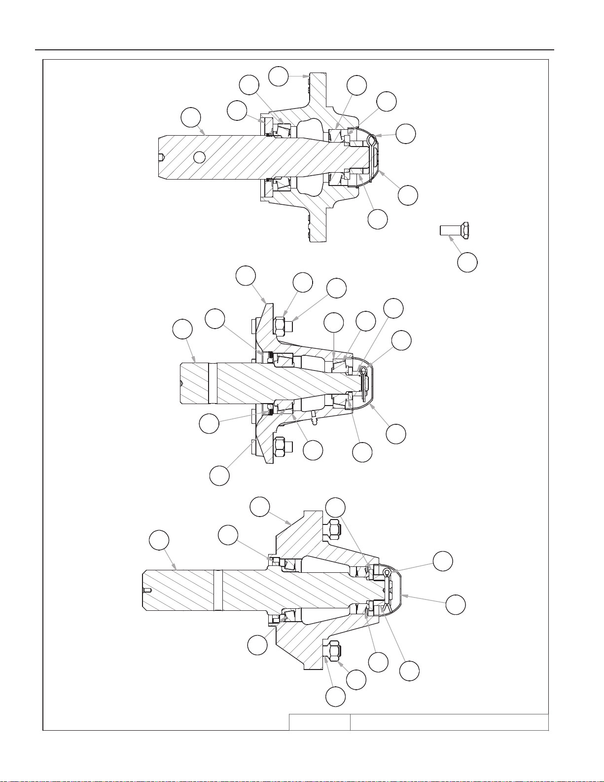
PARTS
5
8
4
9
1
3
10
6
2
8K1100 HUB
3
10
13
9
5
9
8
8K1105 HUB
4
8
11
12
10
7
1
6
14
4
2
7
6
8K1106 HUB
10/13/2015
3-53
3
2
VRT HUBS.idw/
11
5
7
1
HUB & AXLE COMPONENTS
Page 81
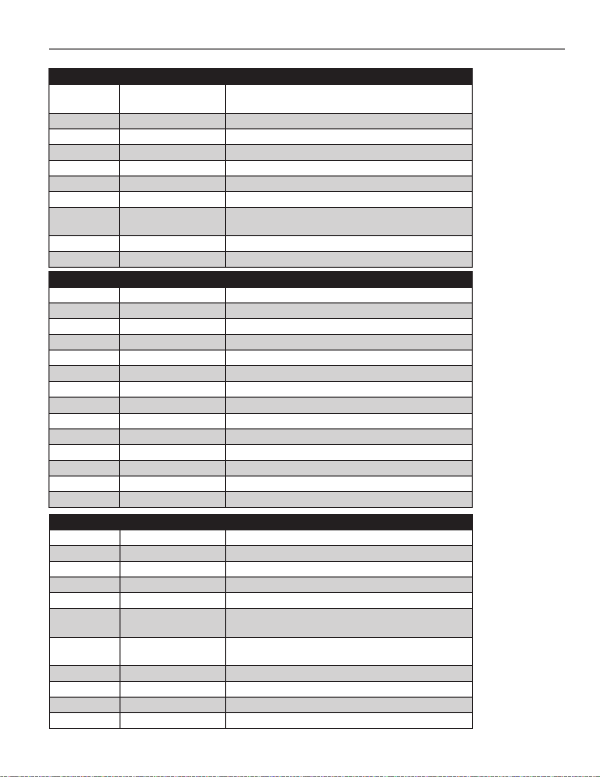
PARTS
VRT HUBS & AXLES
ITEM PART NUMBER DESCRIPTION
1
2 8D5312 NUT 1"-14NF HEX SLOT GR2 PLN
3 8D5319 WASHER 1" AXLE
4 8R6901 AXLE H614 STR 2"CR X 10"
5 8R6911 HUB H614 W/CUPS&ZRK 6 BLT GBGI
6 8R6913 HUB CAP H614 & H618
7 8R6914 BOLT WHEEL 9/16”-18 UNF - 1.25”
8
9 8R6922 SEAL ASSY GBGI H614 HUB 00-
10 8X0415 COTTER PIN 3/16 X 1-1/2"
ITEM PART NUMBER DESCRIPTION
1 8D5312 NUT 1"-14NF HEX SLOT GR2 PLN
2 8D5319 WASHER 1" AXLE
3 8K7111 812 HUB ASSEMBLY
4 8K7113 HUB CAP HD812 DC17
5 8K7117 BEARING INNER HD812 LM3780
6 8K7118 BEARING OUTER HD812 LM2790
7 8K7122 STUD WHEEL 5/8-18UNFX2.5" 978 8K7123 NUT WHEEL BOLT 5/8-18UNF 979 8K7127 SEAL TRPL LIP EXTRNL HD812 06-
10 8K7128 SEAL SLEEVE HD812 06-
11 8K7130 RACE INNER FOR HD812 LM3720
12 8K7132 RACE OUTER FOR HD812 LM2720
13 8K7150 AXLE HD812 X 11.5" (2.5"DIA.)
14 8X0415 COTTER PIN 3/16 X 1-1/2"
8D5217
8D5332
8R6917
8R6925
BEARING IN 517 OUT 614 & 618
RACE H517 & H614 LM48510
BEARING INNER 614
RACE INNER H614 LM603011
ITEM PART NUMBER DESCRIPTION
1 8D5314 NUT 1-1/4"-12 HEX SLOT GR2 PLN
2 8K7122 STUD WHEEL 5/8-18UNFX2.5” 973 8K7123 NUT WHEEL BOLT 5/8-18UNF 974 8K7340 HUB HD817 W/CUPS&SRK 8BLT3LIP
5 8K7341 HUB CAP HD817 DC26
6
7
8 8K7344 SEAL 3"ID HD817 SE42
9 8K7349 AXLE HD817X 15.25" (2.5"DIA.RCVR)
10 8X0328 WASHER 1.312"IDX2.5 OD-1/4" BL
11 8X0414 COTTER PIN 1/4 X 2" YZ
8K7342
8K7346
8K7343
8K7347
BEARING INNER HD817 LM387AS
RACE INNER HD817 382A
BEARING OUTER HD817 LM501349
RACE GBGI & OUTR 817 LM501310
3-54
Page 82
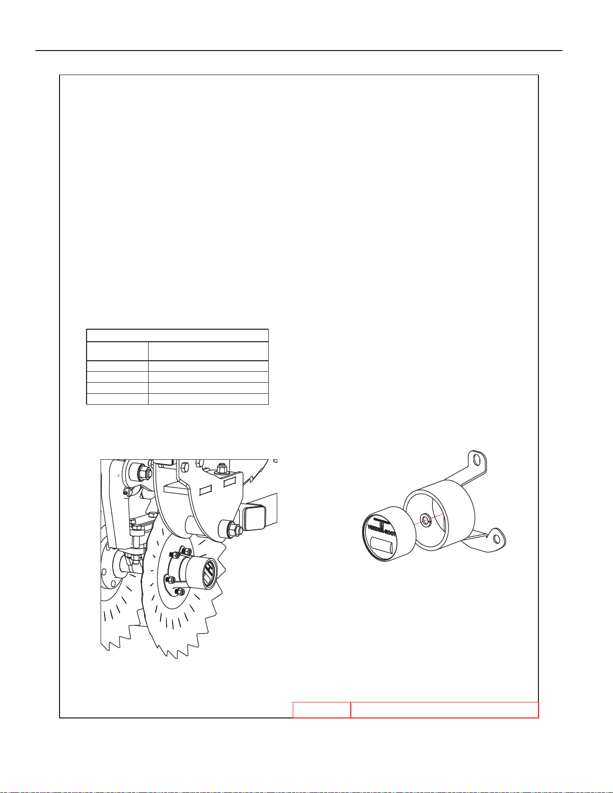
ACREMETER PKG VRT
RENEGADE
6/12/2019
8B9520.iam/
INSTALLATION AND OPERATION
INSTRUCTIONS
FOR 8B9520 ACRE METER KIT
Attach Hub Odometer to mount as shown, using 1/2" Lock Washer.
Replace Dust Cap Protector with Acre Meter Mount. Recommended location
for Acre Meter is the LEFT FRONT blade hub. DO NOT locate Acre Meter beneath
wing hinge, or at widest point of machine. Acre Meter will be damaged if installed
in these locations.
The Hub Odometer is calib
rated at 359 revolutions per acre.
Refer to the chart below for conversion on your implement.
CONVERSION FACTORS
IMPLEMENT
WIDTH
ACRES COVER EQUALS METER
READING MULTIPLIED BY
25' 1.14
30' 1.37
35' 1.60
40' 1.90
PARTS
3-55
Page 83
PART NUMBERS AND DESCRIPTIONS
8A1155 U-BOLT 3/8 X 6-1/16 X 5” SQ
8B0005 GROMMET 1.75”ODX1.375”ID
8B0025 CYL ATTCH SPACER- 1-1/4” PIN
8B0030 CONTROLLER MNT PANEL
8B0037 ROTARY SENSOR
8B0038 WIFI ANTENNA
8B0039 GW300
8B0040 IO400
8B0080B DISK TRIP-PIVOTING
8B0130 DEFLECTOR TRIP
8B0131 DEFLECTOR TRIP-R
8B0156B 3.06”X6.5”X .157” THRUST WASHER
8B1215 WING LOCK TAB VRT
8B1217 WING LOCK TAB SPCR
8B1270B OSC AXLE SPNDLE HLDR 2.5”
8B2000P VRT SCRAPER OUTER-L PNTD
8B2002P VRT SCRAPER INNER-L PNTD
8B2005P VRT SCRAPER OUTER-R PNTD
8B2007P VRT SCRAPER INNER-R PNTD
8B2025 PIN 1-1/2” X 5.375” YZ
8B2175 HYD CYL 2.0 X 1.75” HYD BSKT
8B2490 WING END TIE TUBE
8B2495 ATTCHMNT ARM MNT EXT
8B2495P 8B2495 PAINTED
8B2497 DEFLECTOR ARM MNT EXT
8B2500P HITCH VRT RNGD 35’-40’-PNTD
8B2505P HITCH VRT RNGD 25’-30’-PTD
8B2510P FRAME CENTER RNGD 35’-40’-PTD
8B2515P FRAME WING RNGD 25’-30’ R-PTD
8B2520P FRAME WING RNGD 35’-40’ L-PTD
8B2522P FRAME WING RNGD 35’-40’ R-PTD
8B2525P FRAME WING RNGD 25’-30’ L-PTD
8B2527P FRAME WING RNGD 25’-30’ R-PTD
8B2532 WING REST TUBE 25’-30’
8B2535 DEPTH CNTRL VLV MNT
8B2536 SPACER .76”ID X 4”
8B2537 ANTENNA MNT
8B2538 HYD VLV BLOCK MOUNT
8B2540 LIFTARM OSC AXL-RNGD
8B2542 CYL ATTCH 320/70R15
8B2550 LIFTARM GAGEWHL
8B2551 CYL ATTCH 280/70R15
8b2558 CYL ATTCH WINFOLD 25’-30’
8B2560 TRANSREST MNT PLATE
8B2800 BLADE ANGLE CYL ATTCH
8B2805 BLADE ANGLE LEVER MNT
8B2810 LINK-MASTER BLADE ANGLE
8B2815 LINK-BLADE ANGLE
8B2820 LINK-BLADE ANGLE-SENSOR MNT
8B2822 LINK-BLADE ANGLE LEVER
8B2825B RETAINING CAP-PIVOT TRIP
8B2827 LINK SPACER
8B2831 SENSOR LINK-BLADE ANGLE-FLAT
8B2835 SENSOR LINK-GAGEWHL
8B2836 SENSOR LINK MNT-GAGEWHL
8B2840 SENESOR LINK-HITCH ANGLE
8B2841 SENSOR LINK MNT-HITCH ANGLE
8B2845 SENSOR LINK-DEPTH CNTRL
8B2847 SENSOR LINK-DEPTH CNTRL 25-30’
8B2850 SENSOR LINK-UNIVERSAL
8B2855 ROTARY SENSOR MNT
8B2860 SLEEVE #10 IDX3/8”ODX.40”
8B2865 STANDOFF .56”IDX1”ODX4.35”
8B2867 STANDOFF .56”IDX1”ODX6.10”
8B2996B BLADE MODULE 35’ WING L-R
8B2997B BLADE MODULE 35’ WING L-F
8B2998B BLADE MODULE 35’ WING R-F
8B2999B BLADE MODULE 35’ WING R-R
8B3000B BLADE MODULE 40’ WING L-F
8B3001B BLADE MODULE 40’ WING R-F
8B3002B BLADE MODULE 35’-40’ CNTR L-F
8B3003B BLADE MODULE 35’-40’ CNTR R-F
8B3004B BLADE MODULE 40’ WING L-R
8B3005B BLADE MODULE 40’ WING R-R
8B3006B BLADE MODULE 35’-40’ CNTR L-R
8B3007B BLADE MODULE 35’-40’ CNTR R-R
8B3020B BLADE MODULE 30’ WING L-F
8B3021B BLADE MODULE 30’ WING R-F
8B3022B BLADE MODULE 25’-30’ CNTR F
8B3023B BLADE MODULE 25’-30’ CNTR R
8B3024B BLADE MODULE 30’ WING L-R
8B3025B BLADE MODULE 30’ WING R-R
8B3026B BLADE MODULE 25’ WING R-R
8B3027B BLADE MODULE 25’ WING L-R
8B3028B BLADE MODULE 25’ WING L-F
8B3029B BLADE MODULE 25’ WING R-F
8B3990 DUST CAP GUARD 8B4000/8B4001
8B4000 DBL TILLAGE HUB MAINTFREE
8B4001 SNGL TILLAGE HUB MAINTFREE
8B4019 NUT NYLOCK FLNG 1/2”-20
8B4040 HYD CYL 4 X 4” REPHASE
8B4540 HYD CYL 4.5” X 4” REPHASE
4-1
Page 84
PART NUMBERS AND DESCRIPTIONS
8B7125 FRAME PKG 26’-30’ VRT
8B9100 SUB-ASSY TRANSREST/CNTRL-35-40
8B9110 SUB-ASSY HYD BLOCKS
8B9115 SUB-ASSY FOLD CYL ATTCH-35-40
8B9125 SUB-ASSY LIFTARM VF385/65R22.5
8B9130 SUB-ASSY LIFTARM IF285/70R19.5
8B9135 SUB-ASSY GAGEWHL IF280/70R15-L
8B9140 SUB-ASSY GAGEWHL IF280/70R15-R
8C1755 U-BOLT 3/4 X 6-1/16 X 6” SQ
8D0340 U-BOLT 3/4 X 4-1/16 X 7-3/4” SQ
8D0760 HITCH ARTIC. BALL CAT 4
8D0770 HITCH ARTIC. BALL CAT 5
8D2470 SAFETY CHAIN 7/16” X 5’
8D2480 SAFETY CHAIN 61000# 5/8” X 66”
8D3046 IF280/70R15 134D ON 15X10X6WHL
8D8523 JACK 8000# DROPLEG 5/8X4.25PIN
8D9108 ROLL PIN 1/4 X 2” YLW ZNC
8D9110 HAIR PIN CLIP LARGE(1”CYL PIN)
8H1290 BOLT-SPRINGROD 7/8” X 29”
8H1295 SPRING-COMP - 1.71”ODX7”X.262”
8H2005 CYLINDER SPACER
8H2716B RLLNG BSKT ASSY 6FT
8H2718B RLLNG BSKT ASSY 8FT
8H2719B RLLNG BSKT ASSY 10FT
8H3000 MNT HEAD HRRW/HYD BSKT
8H3040 SUB-ASSY HRRW ARM-32”
8H3080 SUB-ASSY HYD BSKT ARM-57”
8HD5151D CROSS TUBE W/FLATS 8’ QADJ
8HD5181 EXT BRKT QADJ 2ND ARM 15”
8HD5361Q 6’ 3BR M104SECT ASSY QADJ
8HD5381Q 8’ 3BR M104SECT ASSY QADJ
8HD5401Q 10’3BR M104SECT ASSY QADJ
8J1026 CLTR BLADE FLAT .256X26” 5BLT
8J5300 TEE #6 JIC (MALE) 3X
8J5310 #10 JIC (MALE) 3X TEE
8J5312 TEE #10JIC(M2X)X3/4-16ORBBRNCH
8J5520 3/4” -16 ORB X #10 JIC(M) STR
8J5680 3/4”-16 ORB X 3/4”-16ORB UNION
8J5690 3/4-16X3/4-16 ORB M-SW90*UNION
8J5700 #6 JIC(F-SW) X #6 JIC(M)90*ADP
8J5710 #10 JIC(F-SW)X#10 JIC(M)90*ADP
8J6010 3/4”-16 ORB X #6 JIC(M)90*ADP
8J6020 3/4”-16 ORB X #10 JIC(M)90*ADP
8J7040 THERMAL RELIEF MANIFLD 4000PSI
8J7116 3/4”-16 ORB(2X)1WAY 1/16”RESTR
8J7216 #6JIC(M)X6JIC(F)1/16”RSTR GOLD
8K1100 HUB&AXLE ASSY 614(GBGI-2”RCVR)
8K1105 HUB&AXLE ASSY HD812(2.5”RCVR)
8K1610 PIN 3/4 X 6 1/4” SAFETYLOCK
8K4922SM 22 X 6.5MM SAMURAI
8K4946 CLAMP FLAT DSK CHSL HUB
8K7410 285/70R 19.5 ON 19.5X8.25X8WHL
8K8005 TUBE LGHT BRKT SHRT 1.5SQ PNTD
8K8020 MOUNTNG BRCKT LIGHT 00-
8K8067 DUST CAP FOR 7PIN CONNECT00-
8K8090B LIGHT LED AMBER 2WR DTSCH 12-
8K8095B LIGHT LED RED 3WIRE DTSCH 12-
8K9106 PIN 1-1/4 X 4-3/8” HARDENED
8K9110 PIN 1-1/4 X 6-13/16” HRDND
8K9640 HYD CYL 4 X 36” W/3” STOP TUBE
8K9650 HYD CYL 5 X 36” W/3” STOP TUBE
8L0258 U-BOLT 5/16 X 1-1/2 X 2-1/2”SQ
8L4702A CENTER HOSE PROTECTR BRKT
8N0200 BULKHEAD PLATE - HITCH
8N0201 BULKHEAD PLATE - WING
8N0700 HYD HOSE ARM
8N0703 HYD HOSE TIP HOLDER-3 PAIR
8N0705 MANUAL HOLDER MNT
8P3910 PIN 2 X 13-1/2” HARDENED
8R6914 BOLT WHEEL 9/16”-18 UNF- 1.25”
8S1120 SIGN SLOW MOVING VEHICLE(SMV)
8S1124 MOUNTING SOCKET SMV SIGN ZDI
8S1126 MNT SPADE W/HRDWR SMV SIGN
8T1045 HYD CYL 4.5 X 10” REPHASE 96-
8T1050 HYD CYL 5.0 X 10” REPHASE 96-
8T1055 HYD CYL 5.5 X 10” REPHASE 96-
8T1060A HYD CYL 6 X 10” REPHASE
8T2040 HYD CYL 4” X 4” 3500PSI 09-
8T3300 PIVOT BOLT CHSLTRP&WNGLFT YZ
8T3620 PIN 1-1/2 X 12-1/2” HRDND&ZINC
8T3640 PIN 1-1/2 X 19” HARDENED 98-
8T4350 TRNS LCK W/UHMW10.5”(2.4RD)
8X0002 BOLT 3/8-16NC X 1” GR5 ZDI
8X0010B SCREW, ALLEN 1/4-20 X 1-1/4” ZP
8X0015 BOLT 3/8-16NC X 3-3/4” GR5 ZDI
8X0017 BOLT 3/8-16NC X 5” GR5 ZDI
8X0021 BOLT 5/16-18NC X 3/4” GR5 ZDI
8X0021B BOLT 5/16-18NC X 1-1/4”GR5 YZ
8X0024 BOLT 5/16-18NC X 2-1/2” GR5 YZ
8X0030 BOLT 5/16-18NC X 5” GR5 ZDI
8X0044 BOLT 7/16-14NC X 3-1/2”GR5 ZDI
8X0066 BOLT 1/2-13NC X 1-3/4” GR5 ZDI
4-2
Page 85
PART NUMBERS AND DESCRIPTIONS
8X0070 BOLT 1/2-13NC X 3-1/4” GR5 YZ
8X0073 BOLT 1/2-13NC X 5” GR5 YZ
8X0074 BOLT 1/2-13NC X 4-1/2” GR5 ZDI
8X0082 BOLT 1/2-13NC X 6-1/2” GR5 YZ
8X0083 BOLT 1/2-13NC X 8” GR5 ZDI
8X0095 BOLT 5/8-11NC X 5” GR5 ZDI
8X0105 BOLT 3/4-10NC X 1” GR5 YZ
8X0110 BOLT 3/4-10NC X 1-1/4” GR5 YZ
8X0113 BOLT 3/4-10NC X 5” GR5 YZ
8X0114 BOLT 3/4-10NC X 3” GR5 YZ
8X0115 BOLT 3/4-10NC X 3-1/2” GR5 YZ
8X0116 BOLT 3/4-10NC X 6” GR5 YZ
8X0118 BOLT 3/4-10NC X 4” GR5 ZDI
8X0118A BOLT 3/4-10NC X 4-1/4” GR5 YZ
8X0119 BOLT 3/4-10NC X 7.5” GR5 ZDI
8X0120 BOLT 3/4-10NC X 9” GR5 YZ
8X0121 BOLT 3/4-10NC X 6-1/2” GR5 YZ
8X0122 BOLT 3/4-10NC X 4-1/2” GR5 YZ
8X0123 BOLT 3/4-10NC X 5.5” GR5 ZDI
8X0137 BOLT 1-8NC X 4” GR5 ZDI
8X0138 BOLT 1-8NC X 5-1/2” GR5 ZDI
8X0146 BOLT 1-8NCX8.5” W/1.5”THD GR5ZDI
8X0152 BOLT 1-1/4-7NC X 3.75 FULLTHD
8X0163 SCREW #10 X 1-1/4” HEX/WSHR HD
8X0202 NUT 3/8”-16NC NY-LOCK GR2 YZ
8X0203 NUT 3/8”-16NC SERFLANG GR2 YZ
8X0206 NUT 10-24 HEX YZ NYLOCK
8X0211 NUT 5/16”-18NC SERFLANG GR2 YZ
8X0222 NUT 1/4”-20NC NY-LOCK GR2 YZ
8X0234 NUT 7/16”-14NC NY-LOCK GR2 ZDI
8X0242 NUT 1/2”-13NC NY-LOCK GR2 YZ
8X0246 NUT 1/2”-13NC SERFLANG GR2 YZ
8X0253 NUT 5/8”-11NC NY-LOCK GR2 YZ
8X0260 NUT 3/4”-10NC HEX GR2 YZ
8X0261 NUT 3/4”-10NC NY-LOCK GR2 YZ
8X0265 NUT 3/4”-10NC CNTRLOCK GR2 YZ
8X0266 NUT 3/4”-10NC SER FLANG GR2 YZ
8X0269 NUT 7/8”-9NC JAM GR2 ZDI
8X0271 NUT 7/8”-9NC NY-LOCK GR2 YZ
8X0274 NUT 7/8”-9NC SERFLANG GR2 YZ
8X0280 NUT 1”-8NC HEX GR2 YZ
8X0281 NUT 1”-8NC NY-LOCK GR2 YZ
8X0282 NUT 1”-14TPI TOPLOCK GR B Z
8X0283 NUT JAM 1.25”-7NC GR2 ZDI
8X0300 LOCKWASHER 5/16” YLW ZNC
8X0306 LOCKWASHER 3/4” YLW ZNC
8X0309 LOCKWASHER 1” YLW ZNC
8X0316 WASHER 1” SAE FLAT YZ
8X0318 WASHER 3/4”(13/16”ID)FLAT YZ
8X0327 WASHER 1-1/4” SAE FLAT YZ
8X0329 WASHER 5/16”(3/8” ID)FLAT YZ
8X0330 WASHER 17/32”ID X 1.25”OD YZ
8X0335 WASHER FENDER #10
8X0402 HAIR PIN CLIP 1/8 X 2-9/16”
8X0440 CLEVIS PIN 5/8 X 3-7/8” ZDI
8X1110 CRG 3/8-16NC X 1” GR2 ZN
8X1115 CRG 3/8-16NC X 1-1/2” GR2 ZN
8X1140 CRG 3/8-16NC X 4” GR2 ZN
8X3080 FLANGEBRNG .469X.375”ID- .25”
8X3110 SLEEVEBRNG 1.125X1” ID- 1”
8X3130 SLEEVEBRNG 1.656X1.5” ID- 1.5”
8X3140 SLEEVEBRNG 2.188X2” ID- 2”
8X3150 SLEEVEBRNG 3.25X3” ID- 3”
8XM0001 SCREW,SS - BTTN HEAD M5 X 35MM
8XM0110 SCREW,SS - BTTN HEAD M6 X 10MM
8XM0200 NUT,SS - NY-LOCK M5
8Z0046 PATENT PENDING DECAL
8Z0052 PATENT DECAL
8Z0075 TRANSPORT LOCK DECAL
8Z0087 DECAL”WARNING”PINCH POINT03-
8Z0099 WARNING JACK DECAL
8Z0100 MADE IN THE USA DECAL
8Z0101 2” SUMMERS DECAL
8Z0202 3.5” SUMMERS DECAL
8Z0206 7.5” SUMMERS DECAL
8Z0276 GENERAL MACHINE CAUTION DECAL
8Z0340 REPHASING CYLINDERS DECAL
8Z0342 INSTALL CYL LOCKS DECAL
8Z0344 DECAL WING DANGER
8Z0345 DECAL - DANGER HYD BSKT
8Z0346
8Z0800 REFLECTOR AMBER ADHSVBCK98-
8Z0805 REFLCTR REDORANGE ADHSVBK99-
8Z0810 REFLECTOR RED ADHSV-BACK 98-
8Z1010 MANUAL HOLDER TUBE
8Z2533 DECAL LIFT-AUX-WING
8Z2541 DECAL - I/O #1
8Z2542 DECAL - I/O #2
8Z2543 DECAL - I/O #3
8Z2544 DECAL - I/O #4
8Z2550 3” X 20.75” VRT-RNGD DECAL
8Z2555 5.5” X 20.75” VRT-RNGD DECAL
ELECTROCUTION-TILLAGE EQUIP. DECAL
4-3
Page 86

History of Summers Manufacturing Co., Inc.
1965 – Summers Manufacturing is founded by Harley Summers, who purchases patent rights for Goebel truck and pickup hoists from the Goebel
Brothers of Lehr, ND. These hoists, produced in Harley Summers’ blacksmith shop the rst year, were distributed nationwide by a Cincinnati, Ohio, dealer. With increasing sales, the company soon outgrows the small shop. Summers wins the Herman harrow contract, beginning
the company’s Herman culti-harrow line. Summers builds a 7,200 square-foot factory in Maddock to meet the demand for truck and pickup
hoists, as well as Herman harrows.
1969 – Firm incorporates and becomes ocially known as Summers Manufacturing Company, Inc.
1970 – Summers purchases rights to manufacture/market the Herman Harrow.
1973 – Company builds new 20,000 square-foot plant and oces in Maddock, adding a 20,000 square-foot assembly plant in the fall of 1975 (com-
pleted in January 1976), bringing total square footage of Maddock factories to 47,000.
1977 – Summers introduces the Agri-sprayer, used in conjunction with the Herman culti-harrow to incorporate herbicides and liquid fertilizer.
1980 – Company purchases manufacturing and distributing rights to Crown rockpickers from Crown Manufacturers of Regina, Saskatchewan. This
forces another expansion project – a 26,000 square foot factory on a 24 acre site in Devils Lake, ND Industrial Park.
1981 – Company establishes a branch facility in Regina, Saskatchewan.
1982 – Devils Lake plant begins operations in January, manufacturing supersprayers and rockpickers. The Maddock factory begins producing the
Superweeder, a combination cultivator and harrow.
1983 – Summers buys manufacturing and distributing rights to the Fargo Field Sprayer line from Mid America Steel (formerly Fargo Foundry),
Fargo. This eld sprayer line is manufactured at the Devils Lake plant. Harley Summers is selected North Dakota’s small-businessman of
the year by the Small Business Administration.
1984 – Herman Diamond Disk, a disk harrow made in a diamond shape to reduce blade breakage from rocks, comes o the assembly line.
1985 – Summers signs a contract with Melroe Company of Bismarck to obtain exclusive manufacturing rights to the Melroe harrow line.
1989 – Summers purchases TorMaster Company of Hordean, Manitoba, giving the company a line of rolling packer equipment, comprised of harrow
packers and hydraulic fold coil packers.
1992 – A new engineering oce/parts department is added to the Devils Lake factory.
1993 – Company adds two new products: a pickup-mounted sprayer with booms of 80 and 90 feet, and the Summers Superharrow, an extra-heavy-
duty residue-management tool designed for the minimum and no-till farmer.
1994 – a 50 by 125 foot addition to the Maddock factory is completed. Construction begins on a 24,576 square-foot addition to the Devils Lake fac-
tory, which enables the company to increase production of truck-mounted and pull-type supersprayers and rockpickers.
1996 – 1500 square foot oce area added to the Maddock plant. Company introduces Chisel Plow with oating hitch and 700# trip assembly.
1997 – 16,800 square foot warehouse in Maddock purchased from local business.
1999 - Company introduces the Ultimate suspended boom trailer sprayer with hydraulic folding booms. Additional sizes added to the Chisel Plow
line, now ranging from 28’ to 54’.
2000 - Company introduces the Supercoulter, the innovative solution for excessive eld residue management on no-till, minimum-till, and conven-
tional-till farming operations.
2001 - Cold storage building completed at Devils Lake. Company extends boom lengths up to 110 feet on the Ultimate Supersprayer.
2002 - Company adds a warehouse and service man in Aberdeen, SD.
2003 - Company introduces the Ultimate NT Supersprayer featuring a bolt on axle for easier adjustment, and a new family of tanks that feature a
drainable sump and a common width dimension.
2004 - A 124 ft. x 310 ft. addition is added onto the current Devils Lake plant.
2005 - The Summers Superroller is added to the “Field Tested Tough” product line. Additional sizes of 56’, 58’ and 60’ are added to the Superchisel
line. Ultimate-Ultra NT Supersprayer introduced featuring 120’ & 133’ booms.
2006 - The Summers Coulter-Chisel, Rolling Choppers and 30’ Superroller were included in product line.
2007 - 62’ & 84’ 5 Section Landrollers and a 20’ Coulter-Chisel were introduced.
2008 - Disk-Chisels, ranging from 16’ to 40’ widths, are added to product line.
2009 – M105 and M108 Mounted Harrows added to selection of Mounted Attachments. SuperHarrow 2650, 50’ SuperCoulter, Hydraulic Fold Roll-
ing Chopper and 36” diameter Landrollers introduced.
2010 – Rolling Basket and 47’ Diamond Disk added to product line. A 124 ft. x 310 ft. addition to Devils Lake factory built for a state of the art
paint system.
2011 – Additional Supercoulter sizes were added along with larger tires for tillage implements. Ultimate and Ultra Supersprayers received an ad-
ditional tank size of 1650 gallons. Front Caster Wheel option was made available for chisel implements.
2012 – 41’, 46’ & 53’ Trail Type Landroller added to product line. Additional Superchisel sizes of 16’ & 20’ were added.
2013 – DT9530 added to product line. Internal Scraper in Rolling Baskets introduced. Finishing Coulter Gang becomes standard on the Diamond
Disk and 2510 DT. Corporate oces opened at Devils Lake plant. New building and location for the Aberdeen warehouse.
2014 – Introduced the VRT2530 (Variable Rate Tillage).
2015 – Introduced the VT Flex Applicator and Spray Fill Xpress.
Summers distributes on a wholesale level to dealers and distributors throughout markets in North Dakota, South Dakota, Minnesota, Montana, Iowa,
Washington, Idaho, Oregon, Utah, Colorado, Kansas, Nebraska, Oklahoma, Texas, Manitoba, Saskatchewan, Alberta, British Columbia, Kazakhstan,
Russia and Australia, making it an international company.
Page 87
. . . Field Tested TOUGH!
®
Tillage
Rock Picker
Land Rollers/Packers Sprayers
Cultivators/Harrows
Mounted Attachments
1-800-732-4347 • www.summersmfg.com
 Loading...