

Page 1
Operation 2-1
USER’S MANUAL FOR THE
IMPORTANT
Before you begin...
Please complete the attached Warranty Registration Card and
return it to CalComp today. (Users outside Europe, Africa and the
Middle East should check the address on the back of the Warranty
Registration Card.)
Failure to return the duly completed Warranty Registration Card
might delay response to your warranty and service enquiries.
Summagraphics is a brand name of CalComp.
NOTE
When selecting software drivers: If the CalComp name is not
mentioned in the list of available software drivers, use
Summagraphics drivers.
Manual Number : MI9938 rev 001 English 08/97
Page 2

User’s Manual SummaPaint PC1500
Operation 2-2
FCC NOTICE
The SummaPaint PC1500 has been tested and found to comply with the
limits for a Class A digital device, pursuant to Part 15 of the FCC Rules. These
limits are designed to provide reasonable protection against harmful
interference when the equipment is operated in a commercial environment.
These cutters generate, use, and can radiate radio frequency energy and, if
not installed and used in accordance with the instruction manual, may
cause harmful interference to radio communications. Operation of this
Printer cutter in a residential area is likely to cause harmful interference in
which case the user will be required to correct the interference at his own
expense.
Caution !
Changes or modifications, not expressly approved by CalComp, who is
responsible for FCC compliance, could void the users authority to operate
this equipment.
DOC NOTICE
The SummaPaint PC1500 does not exceed the Class A limits for radio noise
for digital apparatus set out in the Radio Interference Regulations of the
Canadian Department of Communications.
VCCI-1 (CLASS 1) NOTICE
Page 3

User’s Manual SummaPaint PC1500
Operation 2-3
TABLE OF CONTENTS ...............................................................................Page
1. Section 1
1.1. General information..........................................................................................1-1
1.1.1. Introduction ........................................................................................................1-1
1.1.2. Product features................................................................................................1-1
1.1.3. SummaPaint PC1500 user’s manua l............................................................... 1-3
1.2. Specifications..................................................................................................... 1-4
1.2.1. SummaPaint PC1500.........................................................................................1-4
1.2.2. Media ..................................................................................................................1-4
1.2.3. Tools .....................................................................................................................1-5
1.2.4. Interface..............................................................................................................1-6
1.2.5. Firmware.............................................................................................................. 1-6
1.2.6. Performance ......................................................................................................1-7
1.2.7. Certifications ......................................................................................................1-7
1.2.8. Environmental ....................................................................................................1-8
1.2.9. Electrical.............................................................................................................. 1-8
1.3. Cutter accessories and consumables...........................................................1-9
1.4. Rear panel components ................................................................................1-10
1.5. Front panel controls ........................................................................................1-12
1.6. Powering up the cutter ...................................................................................1-15
1.6.1. Grounding.........................................................................................................1-15
1.6.2. Connecting the computer cables ...............................................................1- 16
1.6.3. Power-up procedure ......................................................................................1-17
1.7. Loading media.................................................................................................1-18
1.7.1. Positioning the pinch rollers ...........................................................................1-18
1.7.2. Feeding and positioning media ...................................................................1-19
1.8. Pick-up roll........................................................................................................1-23
1.9. Media load procedure .................................................................................. 1-25
1.10. Installation of a knife or ballpoint pen.........................................................1-28
1.10.1 Installing a standard tangenti al knife ..........................................................1-28
1.10.2 Installing a knif e for cutting masking stencil or heavy materials .............1-32
1.10.3 Installing a drag knife......................................................................................1- 34
1.10.4 Installing a ba llpoint pen................................................................................1-35
1.11. Installing the ink cartridges............................................................................1-38
Page 4

User’s Manual SummaPaint PC1500
Operation 2-4
1.12. Inserting the ink................................................................................................1-41
1.13. Refilling ink........................................................................................................1-45
1.14. Print & Cut..........................................................................................................1-46
1.14.1 Introduction ......................................................................................................1-46
1.14.2 General .............................................................................................................1-47
1.14.3 Marker specifications......................................................................................1-48
1.14.4 Contour cuttin g with OPO S ...........................................................................1-50
2. OPERATION
2.1. SummaPaint Control .........................................................................................2-1
2.2. The control panel............................................................................................... 2-1
2.2.1 The liquid crystal display...................................................................................2-2
2.2.2 The Reset/Load key...........................................................................................2-3
2.2.3 The Online key....................................................................................................2-3
2.2.4 The Menu key.....................................................................................................2-4
2.2.5 The Enter key ......................................................................................................2-6
2.2.6 The 1 and 2 keys ................................................................................................2-6
2.2.7 The jogging keys ................................................................................................2-6
2.2.8 The Tool Up/Down key......................................................................................2-6
2.2.9 The Tool Select key............................................................................................ 2-7
2.3. Normal Operation..............................................................................................2-8
2.3.1 On line and off line............................................................................................2-8
2.3.2 Local operation .................................................................................................2-9
2.4. The USER CONFIG menu.................................................................................2-10
2.4.1 K nife pressure ...................................................................................................2-12
2.4.2 P en pressure .....................................................................................................2-12
2.4.3 Knife offset ........................................................................................................2-12
2.4.4 Firi ng rate ..........................................................................................................2-12
2.4.5 Velocity .............................................................................................................2-12
2.4.6 Overcut .............................................................................................................2-13
2.4.7 System se tup.....................................................................................................2-13
2.5. System setup ....................................................................................................2-14
2.5.1 Concatenation................................................................................................2-14
2.5.2 S moot hing ........................................................................................................2 -14
2.5.3 Emulate ............................................................................................................ 2-14
2.5.4 Tool.....................................................................................................................2-15
2.5.5 Menu units.........................................................................................................2-15
2.5.6 HPGL resolution ................................................................................................2-1 5
2.5.7 Addressing........................................................................................................2-15
2.5.8 Baud rate ..........................................................................................................2-15
Page 5

User’s Manual SummaPaint PC1500
Operation 2-5
2.5.9 Parity ..................................................................................................................2-16
2.5.10 RTS/DTR ..............................................................................................................2-16
2.5.11 Special load .....................................................................................................2-1 7
2.5.12 Media sensor....................................................................................................2-17
2.5.13 Front sensor.......................................................................................................2-17
2.5.14 Pick-up roll ........................................................................................................2-17
2.5.15 Autoload...........................................................................................................2-17
2.5.16 Cleaning ...........................................................................................................2-18
2.5.17 Tool command.................................................................................................2-18
2.5.18 LOAD ON W CMD............................................................................................2-18
2.5.19 Flex-cut..............................................................................................................2-18
2.6. Internal test menu............................................................................................2-20
2.6.1 Tangential knife calibration...........................................................................2-21
2.6.1.1 Adjust Origin test routine ................................................................................2-23
2.6.1.2 Adjust Lat. test r outine ....................................................................................2-24
2.6.1.3 Adjust Long test routine..................................................................................2-25
2.6.2 Cut border........................................................................................................2-26
2.6.3 M enu plot..........................................................................................................2-26
2.6.4 Confidence cut ...............................................................................................2-27
2.6.5 D I N c u t ..............................................................................................................2-27
2.6.6 Calibration OPO S ...........................................................................................2-27
2.6.7 Optical sensor ..................................................................................................2-28
2.6.8 System tests.......................................................................................................2-28
2.7 System tests ......................................................................................................2-29
2.7.1 Language ........................................................................................................ 2-29
2.7.2 R OM revision.....................................................................................................2-29
2.7.3 S ervice plot.......................................................................................................2-29
2.7.4 S ensor setup .....................................................................................................2-29
2.7.5 Cam sensor.......................................................................................................2-30
2.7.6 Calibration........................................................................................................2-30
2.7.7 R oll test ..............................................................................................................2-30
2.7.8 RS232 test ..........................................................................................................2-30
2.7.9 RAM test ............................................................................................................2-30
2.7.10 Install menu.......................................................................................................2-30
2.7.11 Setup coil ..........................................................................................................2-30
2.7.12 LCD contrast.....................................................................................................2-30
2.8. Printer settings ..................................................................................................2-32
2.8.1 Nozzle test.........................................................................................................2-34
2.8.2 Cartridge cal....................................................................................................2-34
2.8.3 Print mode ........................................................................................................2-35
2.8.4 Direction............................................................................................................2-35
2.8.5 Bi-d ir cal.............................................................................................................2- 35
2.8.6 Print/cut cal......................................................................................................2-36
Page 6

User’s Manual SummaPaint PC1500
Operation 2-6
3. GENERAL INFORMATION
3.1. Maintenance & cleaning................................................................................. 3-1
3.1.1 Cleaning the service station............................................................................3-1
3.1.2 Cleaning cartridges ..........................................................................................3-3
3.1.3 Cleaning the tubes ........................................................................................... 3-4
3.1.4 Evacuation Tool................................................................................................. 3-5
3.1.5 Cleaning the drive sleeves ..............................................................................3-5
3.1.6 Cleaning the sensors.........................................................................................3-7
3.1.7 Cleaning the nose pie ce................................................................................. 3-7
3.1.8 Cleaning the Y-guiding ....................................................................................3-8
3.1.9 Cleaning the encoder strip.............................................................................. 3-9
3.1.10 Cleaning the OPO S system............................................................................3-10
3.2. Operating voltage conversion......................................................................3-11
4. INTERFACE
4.1. Introduction ........................................................................................................4-1
4.2. Interface notes...................................................................................................4-1
4.2.1 System se tup.......................................................................................................4-1
4.2.1.1 MS -DOS or PC-DOS ge nerating system .........................................................4-1
4.2.1.2 Wi ndows 3. xx...................................................................................................... 4-2
4.2.1.3 Wi ndows 95......................................................................................................... 4-2
4.2.2 S erial interface connector on cutter .............................................................4-3
4.2.3 P arallel interface connector on cutter.......................................................... 4-3
4.3. Available serial signals.....................................................................................4-4
APPENDIX A:
Media certification........................................................................................... A-1
APPENDIX B:
Material Safety data sheet ...........................................................................A-3
LIST OF ILLUSTRATIONS
1-1 SummaPaint PC1500, rear view....................................................................1-10
1-2 SummaPaint PC1500, cont roller....................................................................1-11
1-3 SummaPaint PC1500, front view...................................................................1-12
1-4 Earth connectio n.............................................................................................1-16
1-5 Media positioni ng............................................................................................1-19
1-6 Feeding roll media using media flanges.....................................................1-20
1-7 Feeding roll media without using media flanges.......................................1-21
Page 7

User’s Manual SummaPaint PC1500
Operation 2-7
1-8 Pinch roller positioning................................................................................... 1-21
1-9 Closing pinch rollers ........................................................................................1-22
1-10 Media routing - side view..............................................................................1-24
1-11 Media routing using the pick-up roll - front view .......................................1-24
1-12 Removing the knife holder.............................................................................1-28
1-13 Blade assembly................................................................................................1-29
1-14 Nose piece installation ...................................................................................1-29
1-15 Knife holder in sertion.......................................................................................1-30
1-16 Knife depth adjustment .................................................................................1-30
1-17 Knife depth test pattern .................................................................................1-31
1-18 Blade assembly................................................................................................1-32
1-19 Node piece and knife installation for cutting masking stencil or
heavy material.................................................................................................1 -33
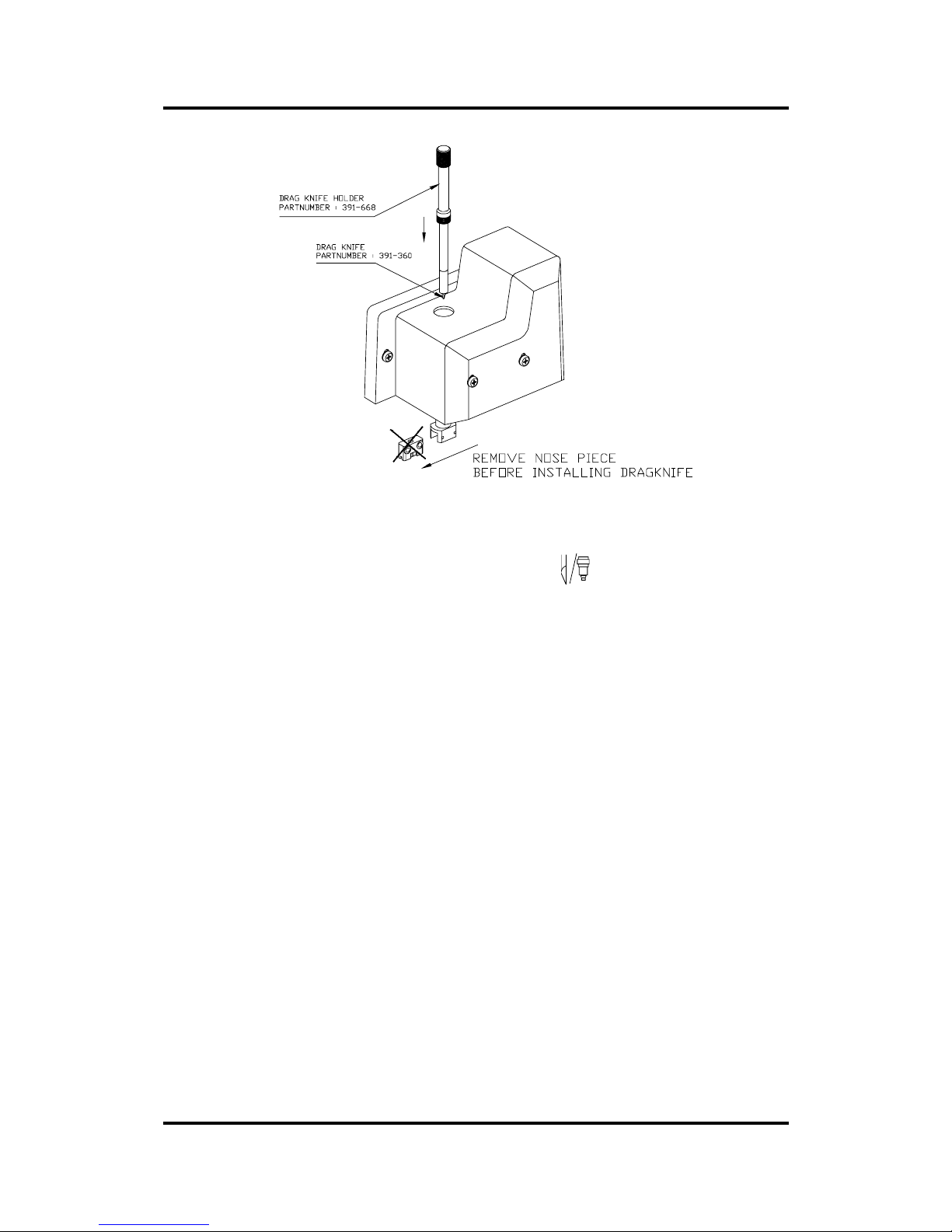
1-20 Drag knife assembly........................................................................................1-34
1-21 Drag knife holder insertion.............................................................................1-35
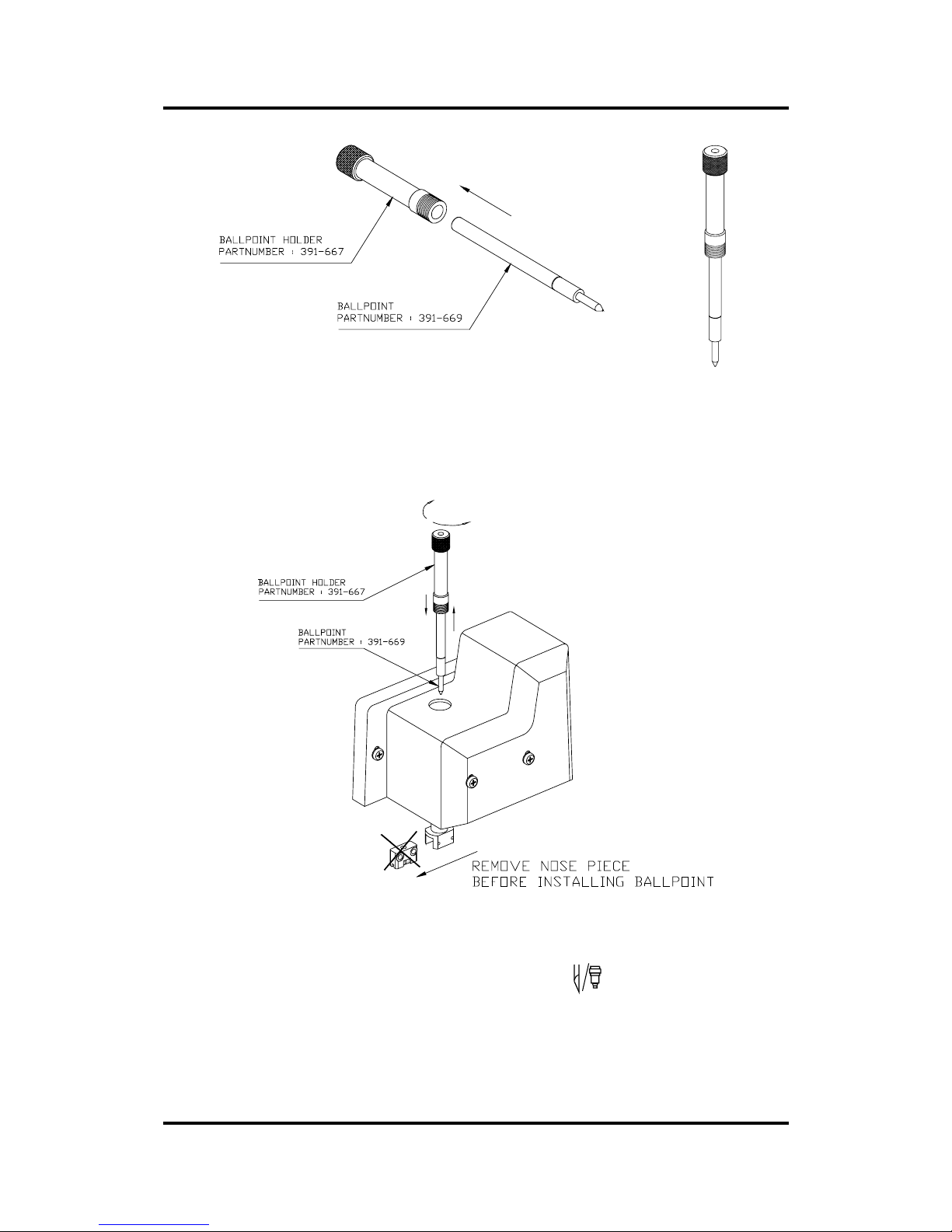
1-22 Ballpoint pen a ssembly...................................................................................1-36
1-23 Ballpoint holder inser tion................................................................................1-36
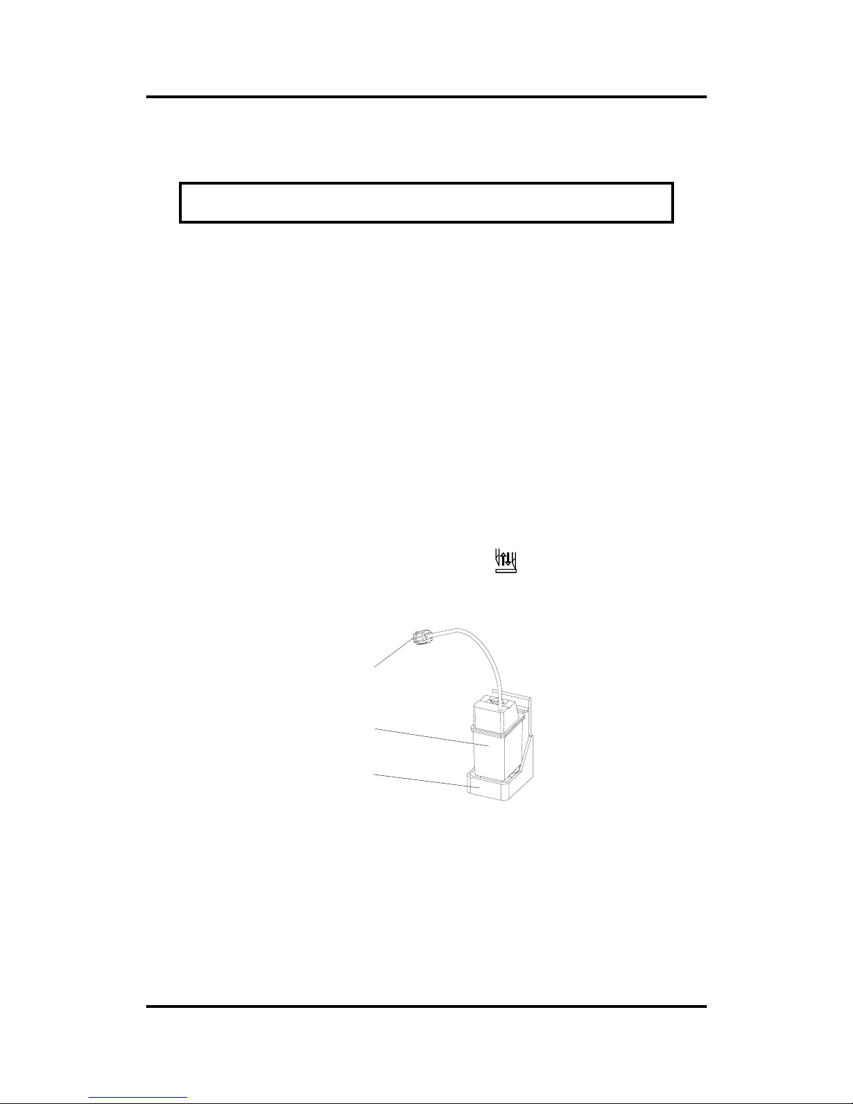
1-24 Ink cartridge and clamp................................................................................1-38
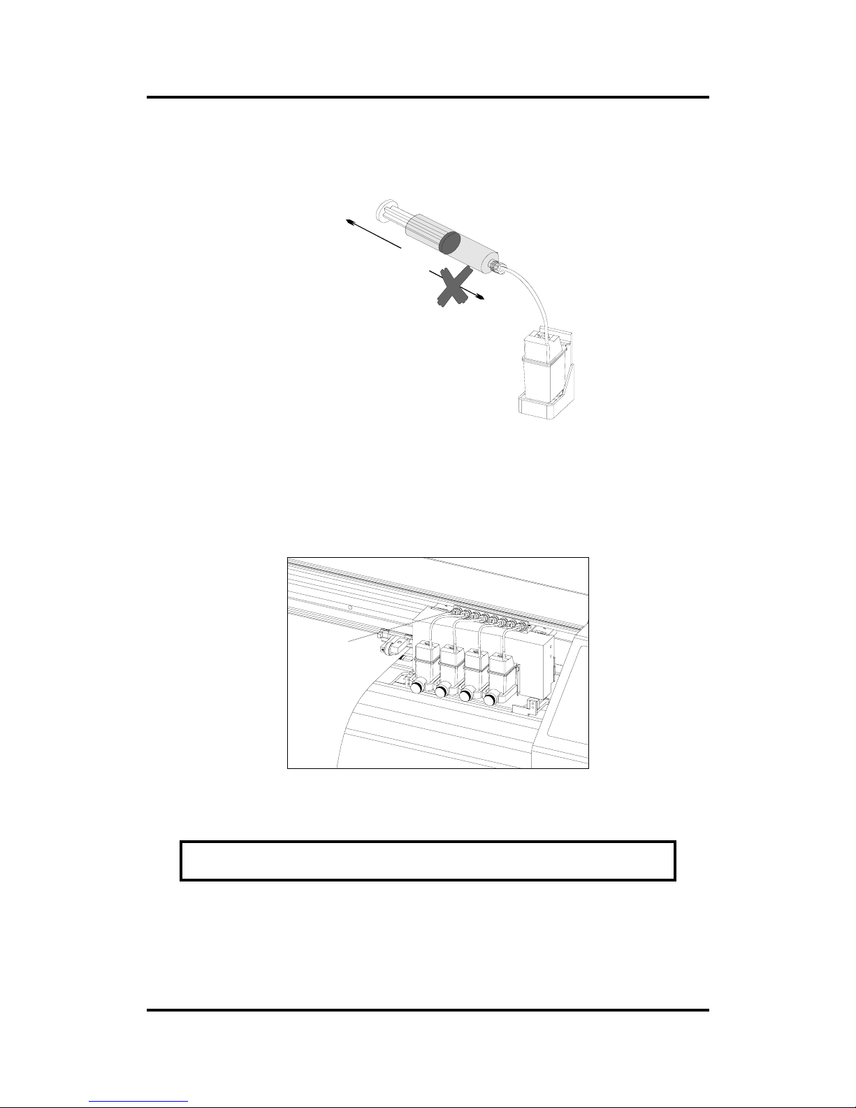
1-25 Ink cartridge bottom view .............................................................................1-39
1-26 Connecting an ink cartridge.........................................................................1-39
1-27 Installation o f an ink ca rtridge.......................................................................1-40
1-28 Position of the ink bottles................................................................................1-41
1-29 Ink bottles and clips ........................................................................................1-42
1-30 Filling the cartridge..........................................................................................1-42
1-31 Filling the cartridge..........................................................................................1-43
1-32 Refilling ink ........................................................................................................1-45
1-33 Marker specifications......................................................................................1-49
2-1 SummaPaint PC1500, cont rol pane l ..............................................................2 -2
2-2 SummaPaint PC1500 Configuration submenus............................................2- 5
2-3 Flowchar t showi ng factory preset menu settings ......................................2-11
2-4 Internal tests submenus ..................................................................................2-21
2-5 Possible knife calibration grounds ................................................................2-22
2-6 Printer settings ..................................................................................................2-33
3-1 Cleaning the service stat ion............................................................................3-2
3-2 Cleaning ink cartridge...................................................................................... 3-3
3-3 Cleaning of the drive sleeves..........................................................................3-5
3-4 Locatin of the sensors .......................................................................................3-6
3-5 Cleaning the Y-guiding ....................................................................................3-7
3-6 Cleaning the enco der strip..............................................................................3-8
3-7 Cleaning the OPOS system..............................................................................3-9
3-8 Power entry module........................................................................................3-1 0
Page 8

User’s Manual SummaPaint PC1500
Operation 2-8
LIST OF TABLES
1-1 SummaPaint PC1500 specifications...............................................................1-4
1-2 SummaPaint PC1500 media specifications..................................................1-4
1-3 SummaPaint PC1500 tools ...............................................................................1-5
1-4 SummaPaint PC1500 interface specificat ions..............................................1-6
1-5 SummaPaint PC1500 firmware........................................................................1-6
1-6 SummaPaint PC1500 performances ..............................................................1-7
1-7 SummaPaint PC1500 environment al specificatio ns....................................1-8
1-8 SummaPaint PC1500 electrical specifications............................................. 1-8
1-9 Summa Paint PC1500 accessories and consu mables ................................1-9
2-1 Content s of the SummaPai nt PC1500 menus...............................................2-6
Page 9

User’s Manual SummaPaint PC1500
Operation 2-9
SECTION 1
GENERAL INFORMATION
INTRODUCTION
The SummaPaint PC1500 has been designed to produce computer-generated graphic designs on cut sheet
or roll media.
This manual is a reference guide for installing and operating the SummaPaint PC1500. This unit h as a
full-color inkjet print head indicated by the “P” and a tangential cutting head indicated by the ‘C’ in the
product designation.
PRODUCT FEATURES
The following are the main features of the SummaPaint PC1500:
• Full-colour inkjet print head
• Fast tangential cutting head
• Variable media widths up to 1420 mm
• Interchangeable drag knife
• Interchangeable ball-point for producing preview plots of sign designs on paper
• 12-key control panel
• Convenient operator control via a 2-line 16 -character liquid crystal display
• Metric or English units
• Menu mode for selection of the printer/cutter's power-up operating configuration
• Up to four separate user configurations stored in non-volatile memory
• Media support system for automatic loading of media with optional “shuffling” to guarantee
tracking of longer signs
• Automatic media pull from roll
• Media sensing
• Pick-up roll for continuous printing
Page 10

User’s Manual SummaPaint PC1500
Operation 2-10
• Big Ink Supply system for continuous working
• Simple origin adjustment to any location
• Draft en Enhanced print mode
• Uni- and bi-directional print mode
• Prime and cartridge alignment test
• Adjustable knife pressure (and offset settings) controlled by microprocessor
• Wide variety of cutting speeds
• Knife depth and offset test
• Print and Cut test
• Extensive internal test routines
• Concatenation and curve smoothing to obtain better cut quality
• Overcut for easy weed ing.
• Communication with host computer via standard serial RS-232-C or Centronics parallel
interface
• User-addressable resolution : 0.1 mm, 0.025 mm,0.001mm, 0.001" or 0.005"
• User-selectable DM/PLTM, HP-GLTM and HP-GL/2TM cutting languages
• Handles the universal HP RTL print language
• Basket (optional)
• Possibility to change quickly between two sets of inks (optional)
SummaPaint PC1500 user MANUAL
This user manual provides the following information :
• Full technical specifications for the SummaPaint PC1500 and the media to be handled
• A complete description of the SummaPaint PC1500 main components
• Step-by-step instructions for cartridge, knife and ball-point installation and media loading
• Instructions for online and local mode ( ) operations
• Instructions for USER CONFIGURATION, INTERNAL TESTS and PRINTER SETTINGS
operations
• Maintenance and cleaning instructions
Page 11

User’s Manual SummaPaint PC1500
Operation 2-11
• Information about the RS-232-C and Centronics interface cables used to inter-connect the cutter and
IBM, IBM-compatible, Apple and Apple-compatible host computer.
Page 12
User’s Manual SummaPaint PC1500
Operation 2-12
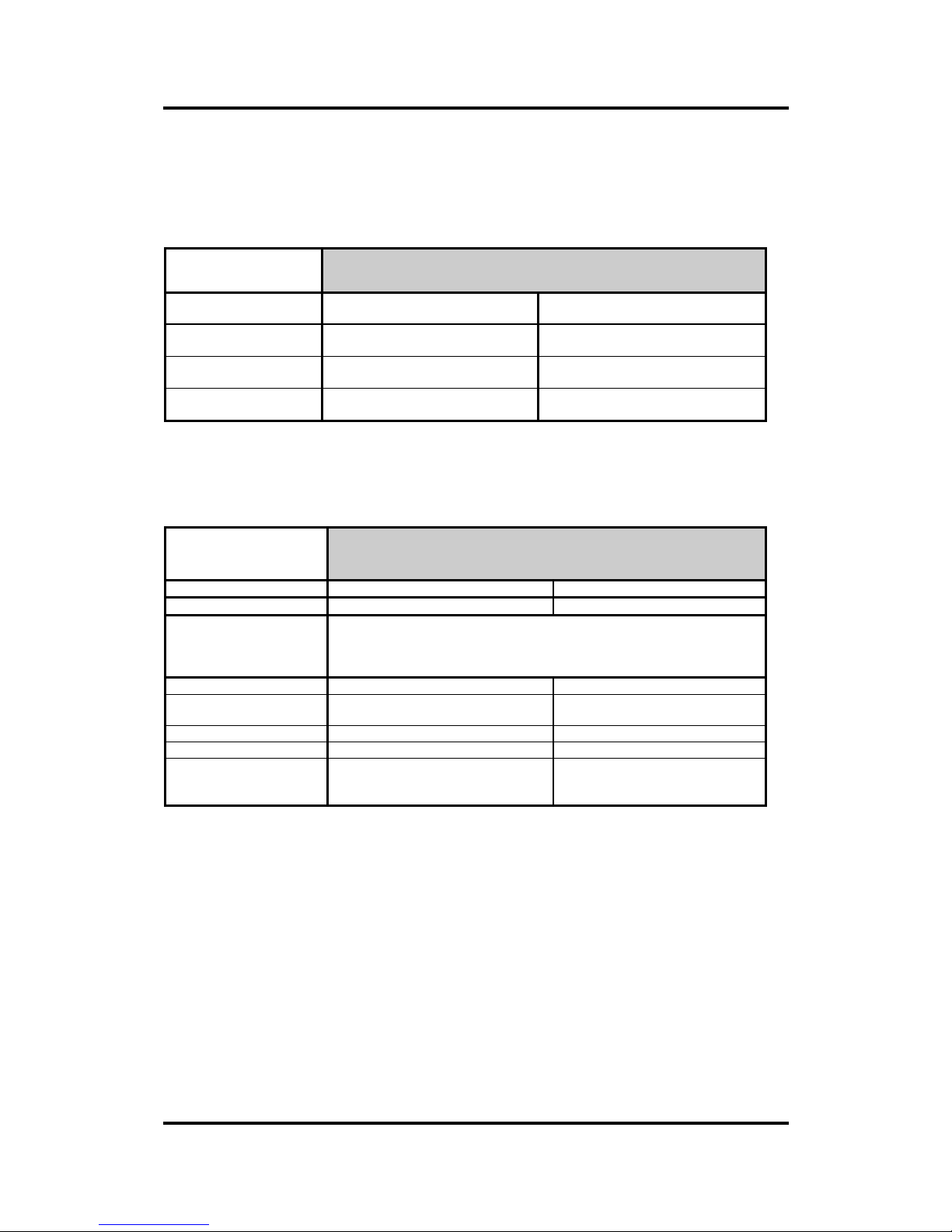
SPECIFICATIONS
PC1500
SummaPaint PC1500
Height
1120 mm
44,1 inch
Width
2450 mm
96,3 inch
Depth
740 mm
29,1 inch
Weight
80 kg
176 lb.
TABLE 1-1 :
SUMMAPAINT PC1500 SPECIFICATIONS
MEDIA
SummaPaint PC1500
mm inch
Width
70 to 1420 3 to 56
Tracking
Performance
- 8 m/26 feet max. within guaranteed specifications * for media narrower than
750 mm (30”)
- 4 m/13 feet max. within guaranteed specifications** for media wider than
750 mm (30”).
Thickness
0.05 to 1.2 0.002 to 0.050
Max. Printing/
Cutting width
1372 mm 54,0 inch
Min. Margin***
25 mm 1,0 inch
Front Margin
25 mm 1,0 inch
Rear Margin
Sensor on
Sensor off
85 mm
65 mm
3,3 inch
2,6 inch
* Media lengths greater than 8 m (26 feet) can be handled, but compliance with specifications is not guaranteed (will
be dependent on media type, media size and other parameters).
** Media lengths greater than 4 m (13 feet) can be handled, but compliance with specifications is not guaranteed
(will be dependent on media type, media size and other parameters).
*** for positioning of the pinch rollers (see section 1.8.)
TABLE 1-2 :
SUMMAPAINT PC1500 MEDIA SPECIFICATIONS
Media Types
A wide range of media types has been evaluated and tested on the SummaPaint PC1500. When using duly
certified media, operation in accordance with the functional specifications of the model is warranted.
Other media should be certified by CalComp before use to ensure performance in compliance with
specifications.
For a full list of all duly certified media suitable for friction drive operation, see Appendix A.
TOOLS
Page 13
User’s Manual SummaPaint PC1500
Operation 2-13
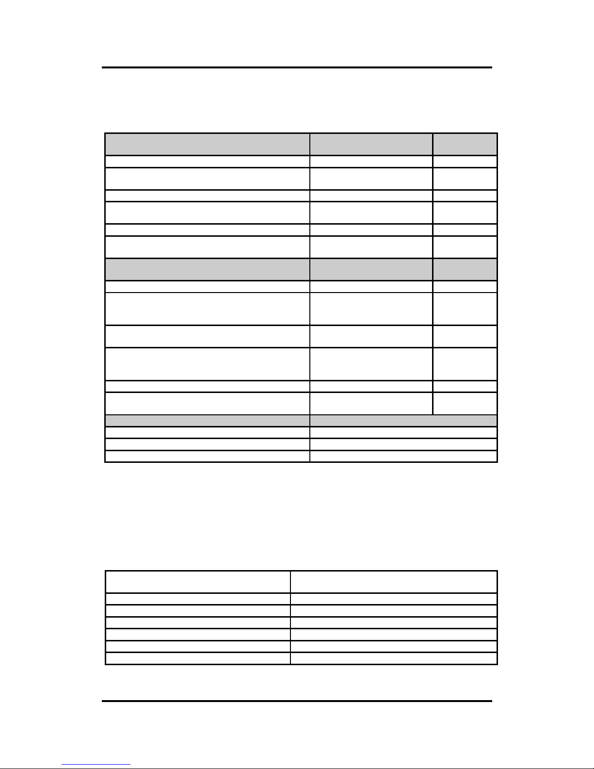
The SummaPaint PC1500 is supplied with 500 ml ink of each color, 4 cartridges, two standard knives (for
vinyl media), one drag knife and one ballpoint pen and some maintenance tools.
Tool Color Quantity
supplied
Cartridge
SummaPaint ink cartridge with special connections
to the big ink supply system.
Yellow, Cyan, Magenta,
Black, Neutral
One of each.
Ink
SummaPaint ink. Yellow, Cyan, Magenta, Black 500 ml of each
color
Pen
Ballpoint pen
(requires a ballpoint pen holder)
black 1 off
(1 off)
Tool Media Quantity
supplied
Tangential Knife
Standard knife
(requires a standard knife holder along with a
standard grey nose piece)
standard, reflective &
fluorescent vinyl types
2 off
(1 off)
Double tip knife for high-density reflective materials
(requires a standard knife holder)
high-density reflective vinyl
types
optional
Knife for masking stencils
(requires a standard knife holder along with black
nose piece)
masking stencils & thick
materials
optional
(optional)
Drag Knife
Standard drag knife
(requires a drag knife holder)
standard, reflective &
fluorescent vinyl types
1 off
(1 off)
Tool usage
syringe Filling and cleaning
cleaning tool Cleaning out tube system
Evacuating tool Deblocking nozzles of cartridges
TABLE 1-3 :
SUMMAPAINT PC1500 TOOLS
To order ink kits, replacement knives and/or pens, contact your local dealer, quoting the part numbers
listed in table 1-9. The SummaPaint PC1500 will only perform according to specifications if the
CalComp genuine tools are installed. Do not replace the tools with products from other manufacturers.
INTERFACE
Communication
standard asynchronous RS-232-C and
Centronics half pitch parallel interface
Serial : I/O Port connector
DB-9P
Mating connector
DB-9S
Byte format
8 data bits, 2 stop bits, no parity
Baud rate
38400, 19200, 9600, 4800, 2400 bps
Parallel : I/O Port connector
Centronics half pitch female
Mating connector
Centronics half pitch male
TABLE 1-4 :
SUMMAPAINT PC1500 INTERFACE SPECIFICATIONS
Page 14

User’s Manual SummaPaint PC1500
Operation 2-14
FIRMWARE
Printing Language
RTL-subset
Cutting Language
HP-GL (758x emulation), HP-GL/2, DM/PL
Supported character sets
Standard ASCII
Supported fonts for cutting
Sans serif (single stroke & medium)
ROM-based plots
Prime plot, Color alignment plot, print and cut plot,
Confidence cut, DIN cut
TABLE 1-5 :
SUMMAPAINT PC1500 FIRMWARE
Page 15

User’s Manual SummaPaint PC1500
Operation 2-15
Performance
Printing & Cutting specifications on 0.05 mm (0.002") wax-backed vinyl, total media thickness not
greater than 0.25 mm (0.010")
Printing Modes
Enhanced or Draft
Uni- or Bi-directional
Printing speed
Draft (full size) Bi-directional
Uni-directional
100 cm / hour
85 cm / hour
Enhanced (full size) Bi-directional
Uni-directional
75 cm / hour
65 cm / hour
Printing resolution
300 dpi
Cutting speed
Axial Cutting speed 50 to 600 mm/s 2 to 24 ips
Default speed 500 mm/s 20 ips
Acceleration 1.5 G
Addressable cutting resolution
0.025 mm, 0.1 mm 0.001", 0.005"
Default cutting resolution
0.025 mm 0.001"
Mechanical resolution
0.0127 mm 0.0005"
Accuracy
0.2% of move or 0.25 mm,
whichever is greater
*
0.2% of move or 0.010",
whichever is greater
*
Knife pressure
0 to 600 gr.
Pen pressure
0 to 600 gr.
*
Excludes differences due to media expansion, stretching, etc.
TABLE 1-6 :
SUMMAPAINT PC1500 PERFORMANCES
Certifications
CE Certificate
FCC Class A
EN 50022 : 1994
EN 50082-2 : 1995
IEC 950, EN 60950
UL 1950
CSA 950
Page 16
User’s Manual SummaPaint PC1500
Operation 2-16
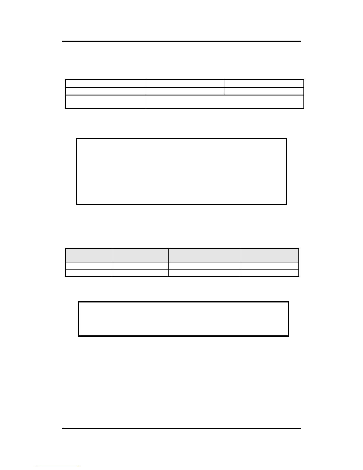
ENVIRONMENTAL
(cutter without media)
Operating Temperature
15 to 35° C 59 to 95° F
Storage temperature
-30 to 70° C -22 to 158° F
Relative humidity
35 - 85 %, non condensing
TABLE 1-7 :
SUMMAPAINT PC1500 ENVIRONMENTAL SPECIFICATIONS
IMPORTANT HINT
The use of dimensionally stable media is an essential pre-requisite to obtain
high cut quality. Additionally, media expansion or contraction may occur as a
result of temperature variations or humidity changes.
To improve the dimensional stability of media, let it stabilise to the current
environmental conditions before usage, for a minimum period of 24 hours.
Electrical
Mains Supply : 48-62 Hz, single phase.
Nominal line Min./Max. line SummaPaint PC1500
Fuse
CalComp order
number
100/120 V AC 89 - 130 V AC T 4A, 250V, 5x20mm MF9004
220/240 V AC 197 - 260 V AC T2A, 250V, 5x20mm MF9003
TABLE 1-8 :
SUMMAPAINT PC1500 ELECTRICAL SPECIFICATIONS
CAUTION
Replace the fuse only with the fuse type specified by CalComp.
Page 17
User’s Manual SummaPaint PC1500
Operation 2-17
CUTTER ACCESSORIES AND CONSUMABLES
The following is an overview of the accessories and consumables available for the SummaPaint PC1500:
Options/
Accessories/
Consumables
SummaPaint PC1500
Quick Start
MI9939
User’s Manual
MI9938
Printer cable
404-923
Power Supply Cablesmarket specificSerial Interface Kit, consisting of :
- 9 pin to 9 pin cable
- 9 pin to 25 pin conv.
- 9 pin to 8 pin DIN conv423-155Extra 4 Ink
supply bottles
400-590
Basket
400-596
SummaPaint Color Kit
Kit with 500 ml of ink and a empty inkcartridge
Yellow : 400-611
Magenta : 400-612
Cyan : 400-613
Black : 400-614
Cleaning tool 400-557
syringe MH9022
Evacuating tool 400-279
Double tip knife
390-551
Ballpoint pen
391-669
Holder for drag knife
391-668
Drag knife (set of 5)
391-360
2 Flanges for media roll ∅ 3 inch
391-510
2 Flanges for media roll ∅ 2 inch
400-561
Manual cut-off razor blades (set of 10)
391-146
Razor blade & holder
391-295
Media :
CalComp has a wide range of material that guarantees high quality images on paper, vinyl,
canvas, clear film, backlite,… . CalComp also has laminate to protect your drawings and use them
outdoor.
TABLE 1-9
SUMMAPAINT PC1500 ACCESSORIES AND CONSUMABLES.
Page 18
User’s Manual SummaPaint PC1500
Operation 2-18
REAR PANEL COMPONENTS
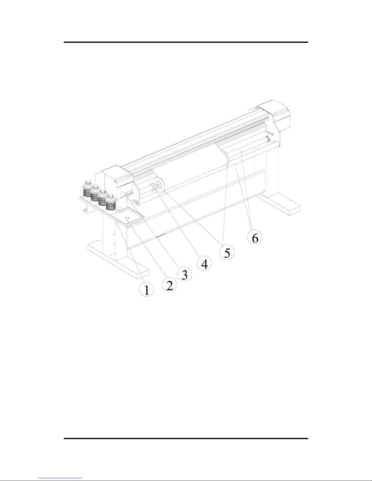
In order to get acquainted with your SummaPaint PC1500, read the following description of the rear panel
components. Figure 1 - 1 shows the location of the main components.
FIGURE 1 - 1
SUMMAPAINT PC1500, REAR VIEW
1. Power Entry Module: - The fuse box and the AC power cord receptacle
are located in the power entry module.
The power-up procedure is explained in detail in Section 1.6.
For information on the conversion of the operating voltage, see Section 3.2.
2. Big ink supply system : - The SummaPaint can be upgraded with a second set of ink.
3. Controller : - For details see further.
4. Roll Media Guide Bushes : - The two guide bushes serve to keep the media roll in place when
media is pulled from the roll.
5. Media Flanges : - The media flanges ensure proper routing of the media roll.
Page 19
User’s Manual SummaPaint PC1500
Operation 2-19
6. Media Support Roller : - Rotating support rollers for the media roll.
FIGURE 1 - 2
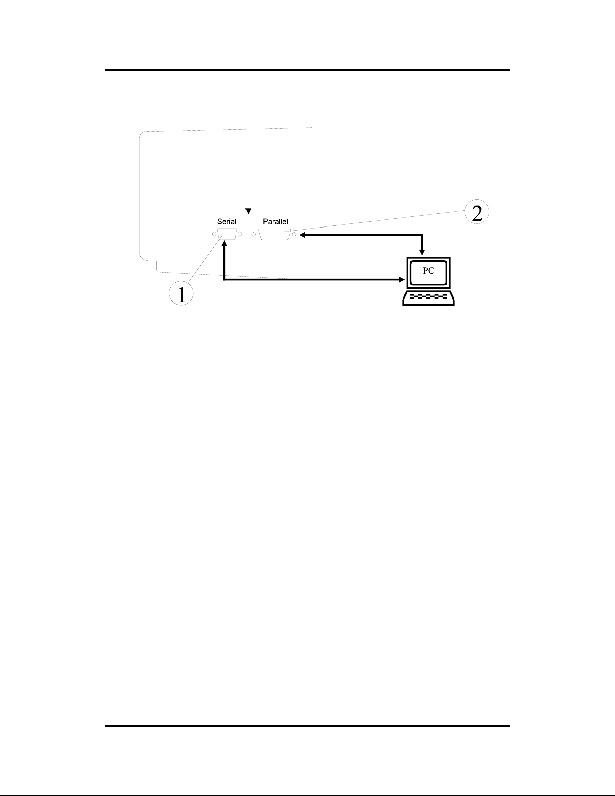
SUMMAPAINT PC1500, CONTROLLER
1. RS-232-C Port* : - This DB-9P connector provides the communication link between the cutter
and a host computer. It allows bi-directional communication between the host computer and the
cutter. This port can only receive cut data.
2. Parallel Port* : - This printer port provides a unidirectional communication
link between the PC1500 and a host computer. The PC1500 can receive
print and cut data, but not transmit data via this port.
* Note : only one interface can be active at a time.
The first port receiving data will be the active interface until the cutter is reset.
Page 20
User’s Manual SummaPaint PC1500
Operation 2-20
FRONT PANEL CONTROLS
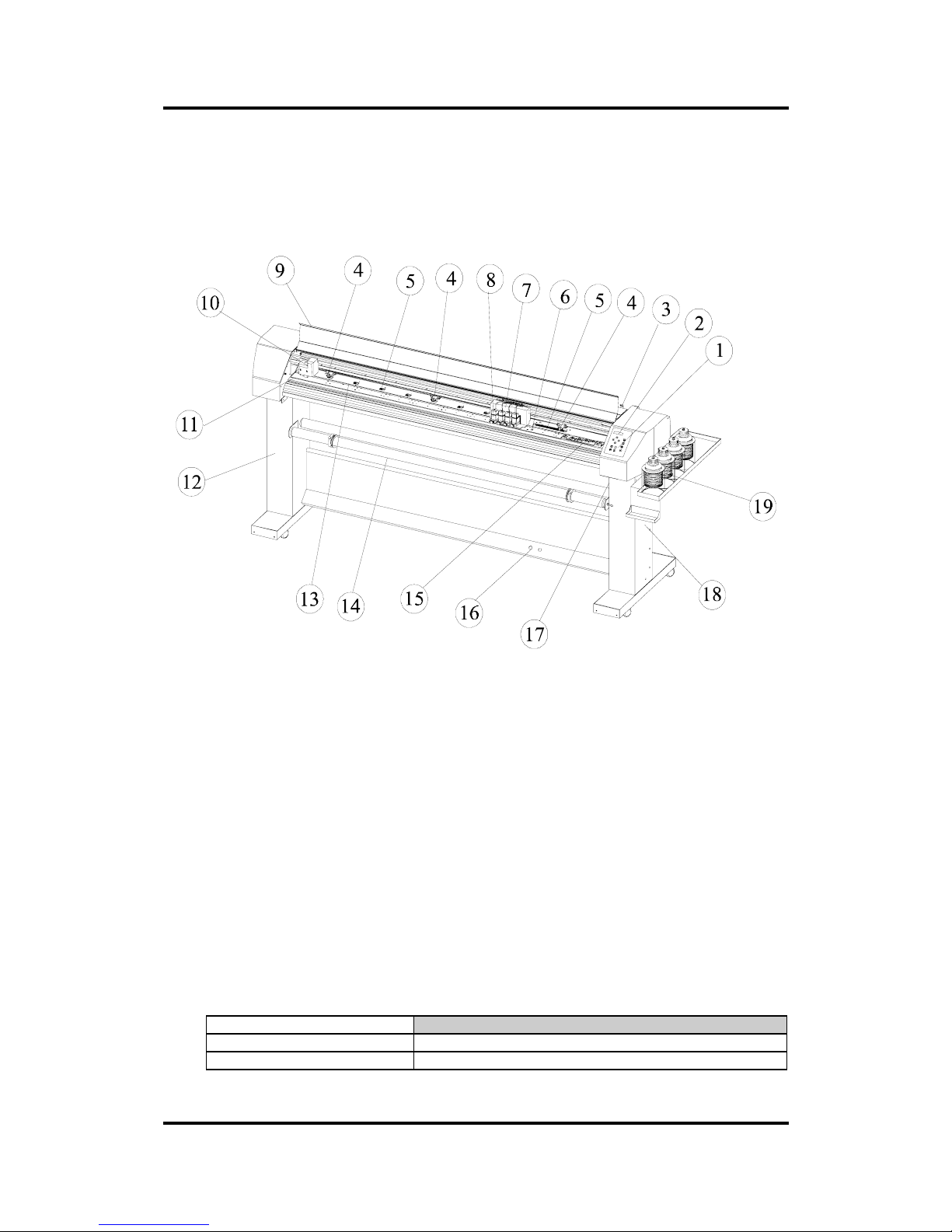
In order to get acquainted with your SummaPaint PC1500, read the following description of the front
panel controls and components. Figure 1 - 3 shows the location of the main components.
FIGURE 1 - 3
SUMMAPAINT PC1500S, FRONT VIEW
1. Control Panel : - The control panel has 12 keys. All machine activity can be initiated from the
control panel. This includes initiating remote mode for computer control, local mode for manual
operation and menu mode. Each control panel function is explained in Section 2.2.
2. Display : - The 2x16 character display informs the user about the current status of the cutting
process or about actions that need to be taken.
3. Pinch roller lever arm : - This lever is used to raise and lower the pinch rollers (Media loading is
discussed in Section 1.8).
4. Pinch rollers : - The pinch rollers (one at each side) hold the media clamped between the rubber
rollers and the media drive sleeves. The PC1500 unit is provided with an extra low pressure roller
in the middle to keep the media flat.
5. Media Drive Sleeves : - The media drive sleeves move the media only when the pinch rollers are
in the ‘down’ position. The following table lists the number of media drive sleeves installed on th e
SummaPaint PC1500
Number of media drive sleeves SummaPaint PC1500
Short sleeve 8
Long sleeve 1
Page 21

User’s Manual SummaPaint PC1500
Operation 2-21
6. Sensors : - The sen sors detect the presence of media to avoid damage to the cutting strip. Upon
powering up the machine, they cause the media to move all the way to the front edge of the platen.
7. Inkjet Carriage : - The inkjet carriage is the mount for the inkjet head.
8. Ink Cartridge : - An ink cartridge is a small reservoir of ink on which a print head is mounted.
(For the installation of the cartridge see further.)
9. Safety Cover : - The safety cover prevents the human body from being hit by the moving carriag e.
Therefore it is advised to close the cover while the unit is working. This cover also prevents dust
from falling on the newly printed drawing.
10. Cutting Carriage : - The cutter carriage is the mount for the tangential cutting head.
11. Manual cut-off knife : - Upon completing a sign, move the media forward by pressing the key.
Use the manual knife to cut the finished sign off the media roll. Leave the loaded media in place
ready to start your next cut by pressing the
key again.
12. Stand : - The stand comes standard with the SummaPaint PC1500.
13. Cutting strip : - Soft strip to avoid damage to the knife tip when no media has been loaded. Since
cutting is done on the cutting strip it is essential that the cutting strip remains intact.
14. Pick-up roll : - The pick-up roll makes it possible to roll up the printed material. This way the
PC1500 can print unattendedly without damaging a drawing.
15. Service station : The service station cleans the printing head and prevents the head from drying out
when the unit is not working. The service station needs to be cleaned regularly.
16. Pick-up sensor : - This sensor senses the vinyl. When the vinyl reaches too close to the ground the
pick-up roll will be activated. This way, it prevents the pictures from touching the ground.
17. Power ON/OFF switch : - This rocker switch sets th e unit’ s pow er to ON or OFF. To switch the
power ON, press the “I” side of the rocker switch. To switch the power OFF, press the “O” side of
the rocker switch.
18. Cartridge compartment : - When a cartridge is not being used, it is advised to place it in a
cartridge clamp. These clamps can be placed in the cartridge compartment.
19. Big ink supply bottles : - The big ink supply bottles can handle 500 ml. ink of each co lour. Th e big
ink supply system enables long unattended printing without refilling the ink.
Page 22
User’s Manual SummaPaint PC1500
Operation 2-22
POWERING UP THE CUTTER
GROUNDING
SAFETY WARNING
An insulated earth conductor must be installed as part of the branch circuit
which supplies power to the wall outlet to which the cutter is connected. The
ground conductor must have the same size, insulation material and thickness as
the grounded and ungrounded branch-circuit supply conductors, but the
insulating sheath should be green, or green with yellow striping.
The ground conductor described above must be grounded at the electrical
distribution board, or, if power is supplied by a separate system, at the power
supply transformer motor / generator set.
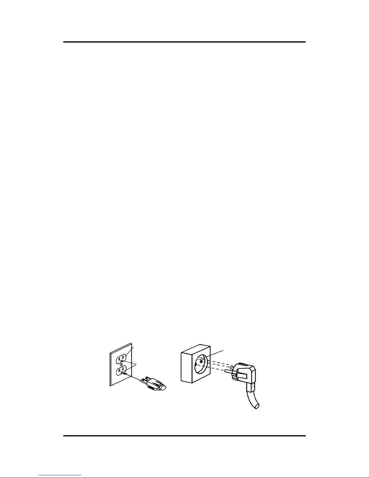
The wall sockets into which the cutter is plugged must be of the grounded type.
The earth conductors serving said wall sockets must be properly connected to
earth.
CAUTION
Before plugging in the cutter’s power cord to a power source, make sure the
unit has the right fuse installed in the power inlet module. (T4A for 100 /120V
or T2A for 220 / 240 VAC) (see section 3).
See Table 1-8 for the minimum and maximum operating voltage for the different voltage ratings.
For information on the exact fuse ratings, see Section 3.
Plug the power cable in the inlet at the rear of the stand (right hand leg), and
plug the other end of the power cable into a properly grounded electrical
outlet of the correct voltage.
MAKE SURE THIS
IS CONNECTED TO A
MAKE SURE THIS IS
CONNECTED TO A
THREE-PIN
PLUG
EUROPE:
USA
OUTLET
:
THREE-PIN
KNOWN EARTH
KNOWN EARTH
FIGURE 1 - 4
EARTH CONNECTION
Page 23

User’s Manual SummaPaint PC1500
Operation 2-23
IMPORTANT OPERATIONAL TIP
Your SummaPaint PC1500 must only be used with a power outlet that is
properly grounded to earth. Use of an unearthed outlet exposes the operator to
risk of electric shock and will also lead to malfunctioning of the cutter.
Connecting the computer cables
1. Plug one end of the long serial cable into the unit (at the rear of the right
hand cover) and screw the two long screws tight.
2. Plug the other end of the serial cable into a serial port of the computer (two
extra adapters are available for different port types on the computer side)
and screw the screws tight.
3. Plug one end of the parallel cable into the unit (at the rear of the right hand
cover) where the subscription ‘PARALLEL’ is written. A special clip system
prevents the cable from loosening.
4. Plug the other end of the parallel cable into the parallel port of the
computer and screw the screws tight.
POWER-UP PROCEDURE
SAFE OPERATION
Do not place any objects in front of, or behind, the unit that could interfere with
the operation of the unit. Make sure the media is free to move back and forth.
Keep hands, hair, clothing and jewellery away from moving parts.
Î To power up the your SummaPaint PC1500, proceed as follows:
1. Make sure the unit is either placed on a flat, level and sturdy surface or
securely attached to its stand.
2. Switch on the switch on the left side of the right hand leg.
3. Follow the instructions on the LCD (only by first ti me set up).
• Use the and jogging keys to select the desired language, and press the key
to confirm your selection.
• Select the menu units by means of the 1 and 2 keys.
4. The message "INSERT MEDIA" is displayed on the LCD when no media is loaded
and the pinch rollers are in the up position.
Page 24

User’s Manual SummaPaint PC1500
Operation 2-24
LOADING MEDIA
The following procedures are mainly written for using roll media . When using sheets there are two
possibilities. Firstly, when using long sheets, roll the sheet up so that the alignment is iden tical to that of a
roll. Secondly, when using short sheets, alignment is not so important. If the sheet is cut off
perpendicularly, it can be aligned to the front border.
Positioning the Pinch Rollers
When working with cut sheet or roll media, the traction resulting from the contact b etween the pinch
rollers and the drive sleeves moves the media in the X axis (forward/backward).
Proper movement of the media will only occur if the media is driven by the pinch rollers correctly located
over two drive sleeves.
The pinch rollers are lowered or raised simultaneously by means of the pinch roller lever arm located on
the right hand side of the cutter, next to the control panel. The rollers must be lifted to facilitate vinyl
loading when the media is fed from the rear of the cutter to the front.
When in the up position, the pinch rollers can be moved manually to the left or the right along th e pinch
roller shaft, so that they can be easily positioned in a detent (click position ) where they are to be lowered
to ensure optimum traction on the media.
When the pinch rollers are in the up position, the message "LOWER CAM ROLLERS" is displayed on
the LCD.
CAUTION
Always make sure that the pinch rollers are fully raised before sliding them to
the left or right.
The pinch rollers MUST be positioned correctly and lowered onto the media before an automatic load
sequence is initiated. Make sure that the two pinch rollers are positioned above th e drive sleeves. The left
pinch roller should be positioned in a detent (click position). The right pinch roller shou ld be positioned
somewhere on the long drive sleeve that only has a click position at the beginning and at the end of the
sleeve. The drive drum will move the media only when the pinch rollers are lowered onto the sleeves.
Before lowering the pinch rollers, carefully check the position of the rollers in relation to the drive
sleeves. When the pinch rollers are DOWN, the two rollers must run over the sleeves in order to ensure
proper media traction. It is very important that both media edges always rest on the sleeves in such a
way that the two pinch rollers, which are positioned 3 to 15 mm (0.1" to 0.6") from the media edge, will
run over the sleeves when lowered to the drive drum.
Two, three or more sleeves may be partly or fully covered, depending on the media width used.
The central low-pressure roller is used to enhance media routing and keep the vinyl flat. Ideally, this
roller should be positioned halfway between the two edge rollers and above one of the drive sleeves.
For media widths smaller than 600 mm, the central low-pressure roller can be positioned in the UP
position to disable it.
For printing purposes the central low-pressure roller shou ld also be plac ed in the up position, so that no
track is made on the material.
feeding and positioning media
Page 25
User’s Manual SummaPaint PC1500
Operation 2-25
The loading procedure described below has been found to give excellent repeatability. When loading
media, adhere to these step-by-step instructions strictly.
Î To load media, proceed as follows:
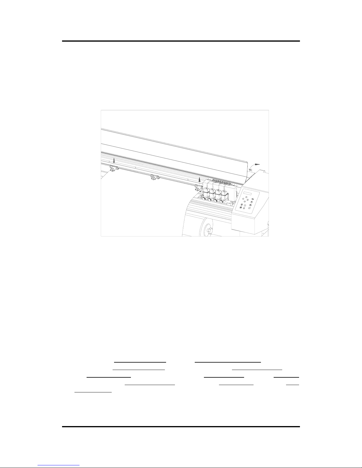
1. Raise the pinch rollers by means of the pinch roller lever arm located on the
right-hand side of the cutter, next to the control panel.
FIGURE 1 - 5
MEDIA POSITIONING
2. When working with roll media proceed by inserting a media flange at each
end of the media roll and tighten the thumbscrew until the media roll is
firmly gripped between the flanges. Make sure the flanges are firmly
pressed against the roll. Place the roll of media on the media support rollers
at the rear of the machine.
3. Position the media roll with flanges on the support rollers at the rear of the
machine.
Slide the two roll media guide bushes under the media roll so that the roll
flanges run into the groove provided in the guide bushes. In this position the
media roll and guide bushes can be shifted from the left to the right.
Start feeding the media from the rear of the machine.
Position the left media edge on the left-most drive sleeve and check
whether the right media edge is positioned over the long drive sleeve. If so ,
the left pinch roller can be positioned in a click position over the left-most
sleeve and the right pinch roller is positioned somewhere over the long
drive sleeve to suit the media width. The pinch roller can be lowered
anywhere between the two click positions of the long drive sleeve to allow
for flexibility in holding any media width.
Page 26
User’s Manual SummaPaint PC1500
Operation 2-26
In circumstances where the above does not work, because your media is
too narrow to reach the long drive sleeve, try positioning the left media
edge over the second left drive sleeve and position the right media edge
somewhere on the long drive sleeve. Repeat this process if the media is
found still to be too narrow, locating the left media edge on the third sleeve
from the left and adjusting the right hand position as previously described.
In all cases, both edges of the media have to run over a drive sleeve. If this
is not the case, reposition the roll of material to comply with the above.
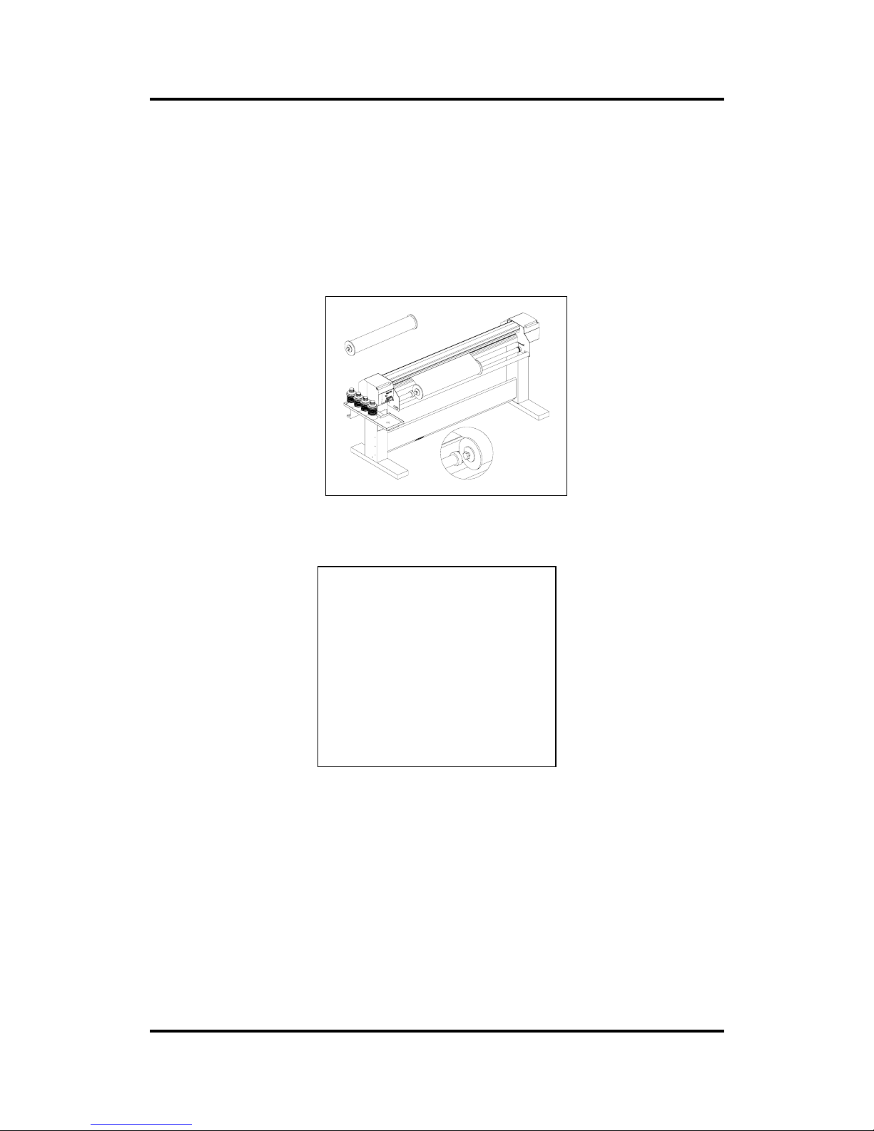
FIGURE 1 - 6
FEEDING ROLL MEDIA USING MEDIA FLANGES
FIGURE 1 - 7
FEEDING ROLL MEDIA WITHOUT USING MEDIA FLANG ES
4. Make sure that the media follows a straight path from the roll of material.
To accomplish this, you can slide the media roll and guide bushes from the
left to the right along the media support rollers.
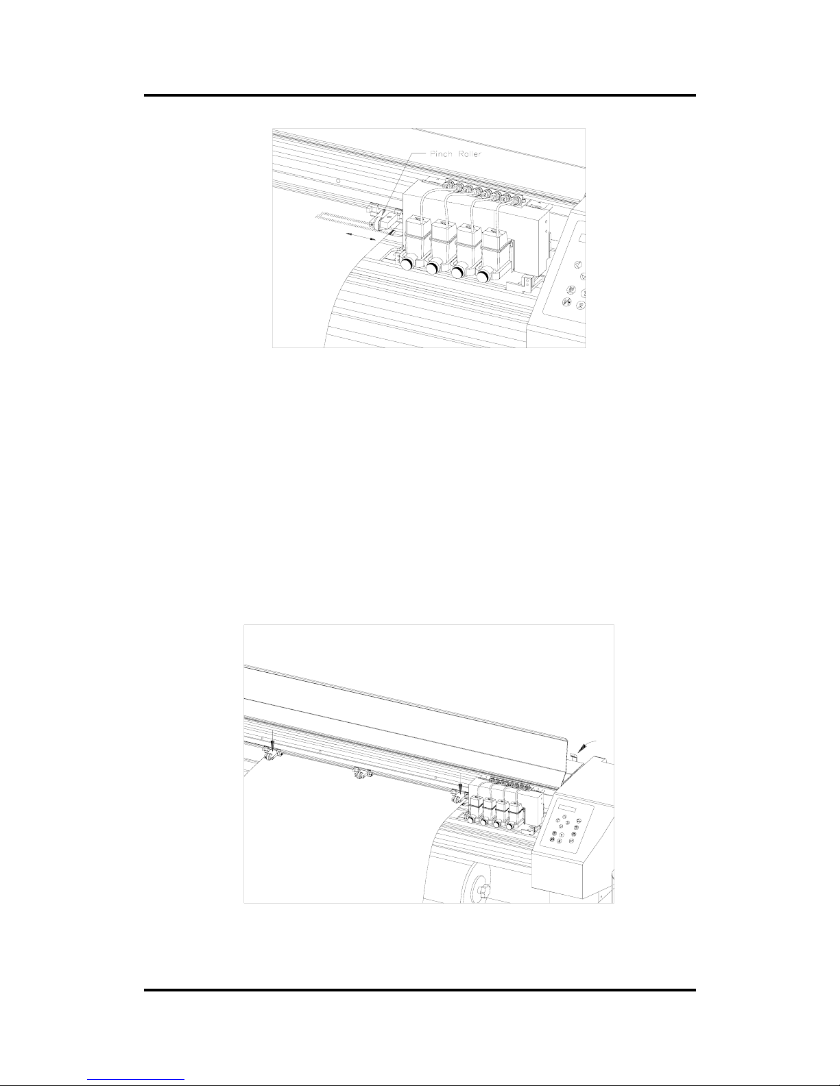
5. The pinch rollers should be positioned over the drive sleeves about 3 to 15
mm (0.1” to 0.6”) away from the media’s outer edges.
Page 27
User’s Manual SummaPaint PC1500
Operation 2-27
FIGURE 1 - 8
PINCH ROLLER POSITIONING
For wide media, slide the central low-pressure roller into position. Ideally, it
should be half-way between the two edge rollers and above a drive
sleeve. Do not use the central low-pressure roller when printing on vinyl or
on paper, as this roller can leave a track or mark on the material.
If the central low-pressure roller does not run over one of the drive sleeves,
you may have to turn the knob on the back of the low-pressure roller to
disable this roller.
6. Lower the pinch roller lever to press the media firmly against the drive
sleeves. After one second the tool carriage automatically moves from the
right to the left to sense the media width that can be used.
FIGURE 1 - 9
CLOSING PINCH ROLLERS
Page 28

User’s Manual SummaPaint PC1500
Operation 2-28
NOTE
It is not necessary to unroll the media manually from the roll. The cutter will
unroll the media automatically during the load sequence.
7. The positioning and routing of sheet material is identical to that of roll
media.
8. The cutter is now ready for the actual load procedure, which may be
controlled from the control panel.
Page 29

User’s Manual SummaPaint PC1500
Operation 2-29
PICK-UP ROLL
NOTE
The pick-up roll is usually used for printing. It is advised not to use the pick-up
roll when you intend to cut designs larger than 60 cm (23”) in order to prevent
the machine from pulling back the media from the pick-up roll and going into
error.
1. Before using the pick-up roll , make sure that the following menu items are
correctly set:
Pick-up roll : on
Front sensor : off
To set these menu items, press the key (MENU) until the message ‘USER CONFIG. 1’ appears
on the display.
Press the jogging key until the message ‘SYSTEM SETUP’ is displayed. Now press the key.
Press the jogging key until the message ‘PICK-UP ROLL’ is displayed. Make sure that this
setting is ‘ON’. If not, press the
key. Press the key to confirm the selection.
Press the jogging key to select ‘FRONT SENSOR’. Make sure that this setting is ‘OFF’. Should
this not be the case, press the
key to switch to OFF. Press the key to confirm this selection.
2. Use the pick-up core with flanges installed on the two front rollers.
3. Open the camrollers.
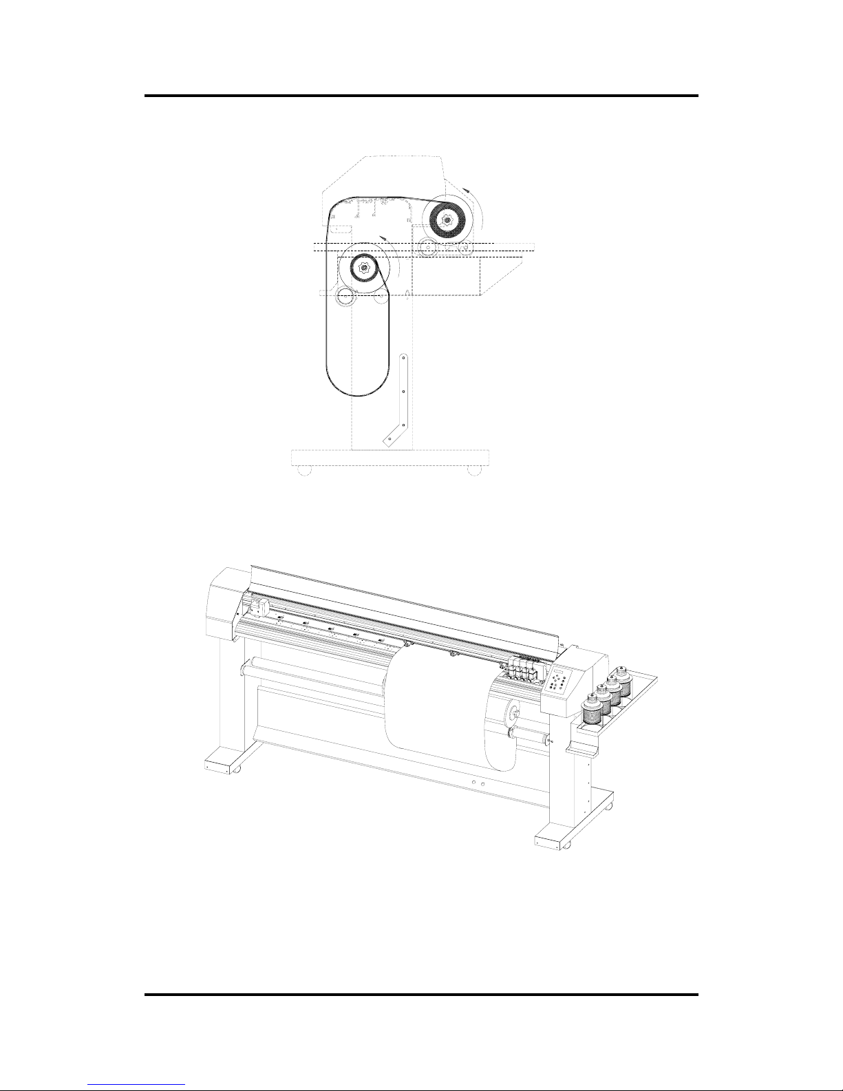
4. Route the media as shown in Figures 10 and 11. Fix the media onto the
pick-up core using some tape. Make sure that the media follows a st raight
path from the pick-up roll to the media roll.
Note: In order to minimise the loss of unprinted vinyl an extra sheet of waste vinyl can be used to
make the routing between the pick-up core and the beginning of the media.
5. Close the camrollers.
Page 30
User’s Manual SummaPaint PC1500
Operation 2-30
FIGURE 1 -10
MEDIA ROUTING - SIDE VIEW
FIGURE 1 - 11
MEDIA ROUTING USING THE PICK-UP ROLL - FRONT VIEW
Page 31

User’s Manual SummaPaint PC1500
Operation 2-31
MEDIA LOAD PROCEDURE
SAFE OPERATION
Do not place any objects in front of, or behind, the cutter that could interfere
with cutter operation. Make sure the media is free to move back and forth.
Keep hands, hair, clothing and jewellery away from moving parts.
Turn the power on and the following message will appear on the LCD screen :
PLEASE WAIT
LOADING...
The cutter will automatically start executing a minimal loading procedure consisting of : - a media width
measurement
- a 45° test
- media is unwound over a length equal to the width measured
between the pinch rollers
When the next display appears, the cutter is ready to receive a file :
500mm/s 120 g K
ONLINE 1
When sending a cut file, the cutter will automatically pull the required media from the roll. The
pulling is done in steps so that for each step the length pulled off the roll is identical to the width
measured between the pinch rollers.
IMPORTANT
Tracking of longer signs is only guaranteed when you perform the full load
procedure !
Proceed as follows to complete the full load procedure (recommended for long signs) :
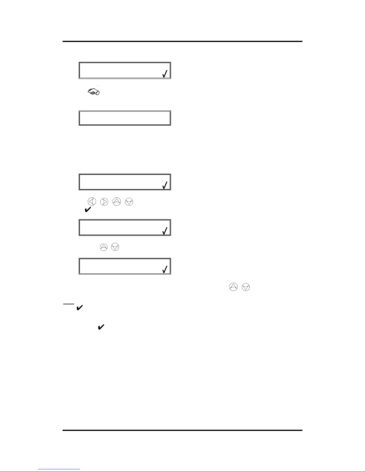
Press the key and the following message will appear on the LCD screen :
Page 32
User’s Manual SummaPaint PC1500
Operation 2-32
SET ORIGIN
X=0 Y=YYYY
Press the key again and the following message will appear on the LCD
screen :
LOAD
1= ROLL 2= SHEET
Press the 1 key if you want to load media from a roll. Press the 2 key if you want to load media in
sheet form.
If you choose “sheet” and the sensors are enabled, then the sheet is automatically loaded.
If you choose “roll”, the following display will appear on the LCD :
SET ORIGIN
X=0 Y=YYYY
Using the , , , jogging keys, you can position the knife (i.e. the origin) at any location.
Press the
key to confirm the selected point of origin.
MEDIA WINDOW
↑↓
By pressing the , jogging k eys, you can enter the length of the media you need for your task.
MEDIA WINDOW
XXXX YYYY
The XXXX-value is the media length you define with the , jogging keys.
The YYYY-value is the cutting width of the media measured by the cutter.
Note : when the media length displayed is zero (0), the default media length will be used.
Press to confirm the length and the cutter will start “shuffling” the vinyl in order to establish a track on
the vinyl.
If you pressed instead of the jogging keys for defining the media window, the default media length is
displayed :
Page 33

User’s Manual SummaPaint PC1500
Operation 2-33
DEFAULT WINDOW
↓↑ XXXX mm
An XXXX-value appears. You can change the default value by pressing the (+10), (-10), (-
100),
(+100) jogging keys.
Press to confirm the length and the cutter will start shuffling the vinyl in order to set a track on the
vinyl.
After shuffling, you get the following display :
500mm/s 120 g K
ONLINE 1
The cutter is now ready to receive a file.
500mm/s 120 g K
*ONLINE 1
The cutter has been selected by the computer.
When the built-in media sensors detect the end of the roll the message END OF
MEDIA will be displayed. The display will show the actual length loaded.
If that area is sufficient, press 1 to ACCEPT.
If not, press 2 to ABORT and the media will automatically return to its origin.
CAUTION
When you accept the loaded area in sheet mode, the cutter will clip the sign to
be cut in case of insufficient media. Compare the area loaded with the area
needed for the sign !
Page 34
User’s Manual SummaPaint PC1500
Operation 2-34
INSTALLATION OF A KNIFE, BALLPOINT PEN
INSTALLING A STANDARD TANGENTIAL KNIFE
SAFETY WARNING
Your cutter uses razor-sharp knives. The knife blades may cause serious
personal injuries if handled without proper care. Use extreme care when
operating the cutter and when installing, removing or handling the knife!
Î To set up your cutter for TANGENTIAL knife operation, proceed as follows.
1. Turn off the unit and move the cutting head manually so that it can be
reached easily.
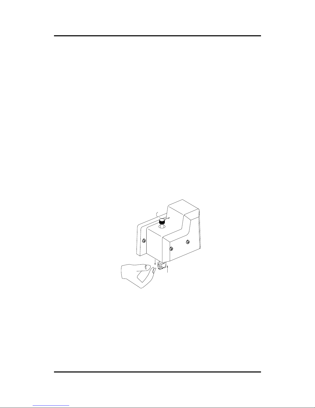
2. Turn the knife holder out of the cutting head while holding the nose piece
at the bottom.
FIGURE 1 - 12
REMOVING THE KNIVE HOLDER
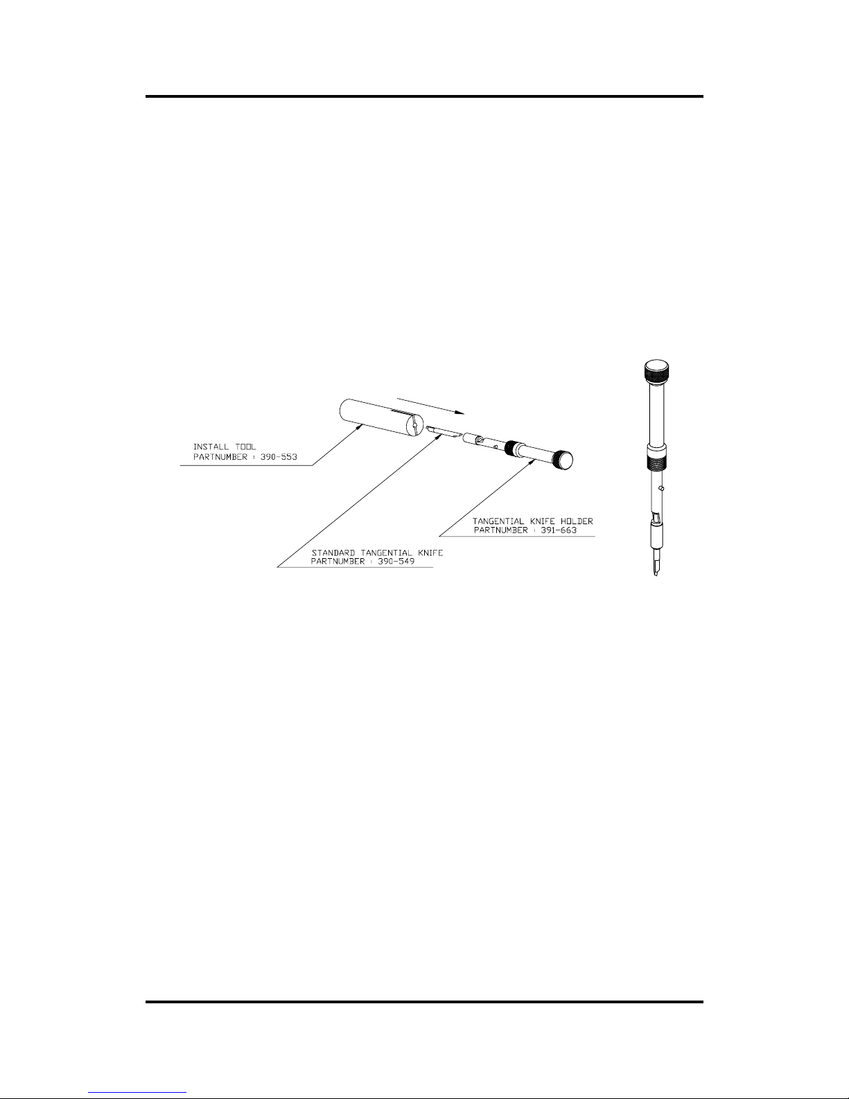
3. Insert the standard knife blade p/n 390-549 into the knife holder as shown in Figure 1 -
13. Make sure the knife blade is firmly fixed into the holder. The knife is firmly fixed
when you cannot remove it manually from the knife holder.
To remove a fixed blade when it has become too blunt, push against the back of
the blade with the tip of a screwdriver. The blade will then jump out of its holder.
This procedure is also valid for the installation of the optional double tip blade p/n
390-551.
Page 35
User’s Manual SummaPaint PC1500
Operation 2-35
FIGURE 1 - 13
BLADE ASSEMBLY
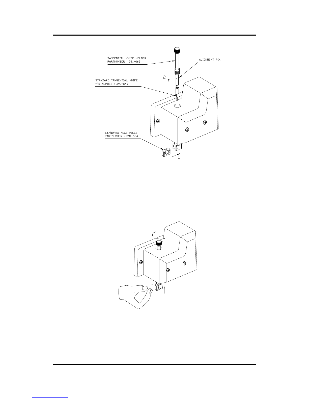
4. Insert the grey nose piece as shown in Figure 1 - 14 until it snaps into t he
nose piece holder.
Page 36
User’s Manual SummaPaint PC1500
Operation 2-36
FIGURE 1 - 14
NOSE PIECE INSTALLATION
5. Gently insert the knife into the tool shaft as shown in Figure 1 - 14. Hold the
nose piece in place with one hand, with the other hand turn the knife
holder anticlockwise until the alignment pin fits into the small notch of the
tool shaft. Now turn clockwise until the knife holder gets grip in the tool
shaft.
FIGURE 1 - 15
KNIFE HOLDER INSERTION
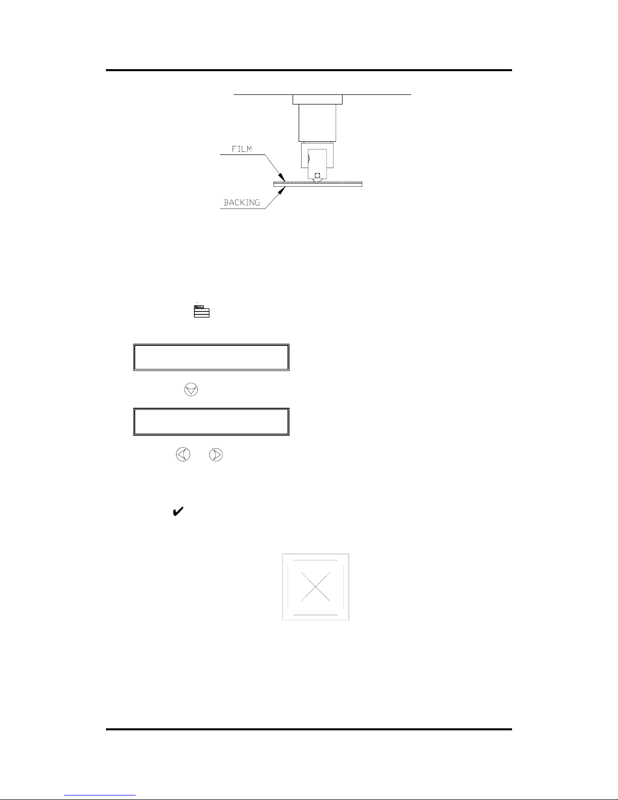
6. Holding the nose piece in place with one hand, adjust the knife depth with the other hand by
turning the knife holder clockwise until the knife tip is just visible from under the nose piece as
shown in Figure 1 - 16.
Page 37
User’s Manual SummaPaint PC1500
Operation 2-37
FIGURE 1 - 16
KNIFE DEPTH ADJUSTMENT
5. Set the knife pressure and knife depth as follows :
Load media and power on the cutter.
Press the key (MENU) key until the message 'USER CONFIG 1' is
displayed on the LCD.
↓ USER CONFIG 1
← →
Press the jogging key until the message 'KNIFE PRESS’ is displayed.
↑↓ KNIFE PRESS
← * 120 g → 1= TEST
Press the or key to modify the knife pressure.
To increase the cutting depth, turn the knife holder clockwise. To decrease the cutting depth turn
the knife holder anticlockwise while holding the nose piece in place with the other hand.
Press the key to confirm the selection.
Press the 1 key to perform a knife depth test as illustrated Figure 1 - 17.
FIGURE 1 - 17
KNIFE DEPTH TEST PATTERN
The knife depth is correctly set when the test pattern is visible on the front side of the media
backing, but not on the rear side of the media backing. In general, you should increase the knife
depth and knife pressure when using thicker types of vinyl.
Page 38

User’s Manual SummaPaint PC1500
Operation 2-38
NOTE
As the ideal knife pressure and depth setting depends upon the thickness and the
type of media to be cut, adjusting the pressure and depth of the knife will
require some practice. In general terms, you should increase the pressure and
depth of the knife when cutting thicker types of vinyl . For thinner types of
vinyl, you will normally have to reduce the knife pressure and depth.
CAUTION
After setting the cutting depth and/or the knife pressure, perform a thorough
visual check of the knife blade, which can be seen protruding from the knife
holder, and test cutting results on a scrap of vinyl media.
Do not operate the cutter if the knife blade cuts through the media backing, as
this will seriously damage the cutter's rubber cutting strip and the knife.
CAUTION
For most vinyl cutting operations, the knife blade tip will be barely visible at
the bottom of the knife tool. If you can clearly see the knife blade tip, you will
probably need to readjust the cutting depth.
To prevent damage to the cutter, check the depth of the knife blade tip and the
quality of the cut each time you load a different type of vinyl into the cutter.
INSTALLING A KNIFE FOR CUTTING MASKING STENCIL OR
HEAVY MATERIALS
The SummaPaint PC1500 can also be operated with a knife for masking stencil. After replacing the
knife the cutter can be used to cut through heavy materials like masking stencil.
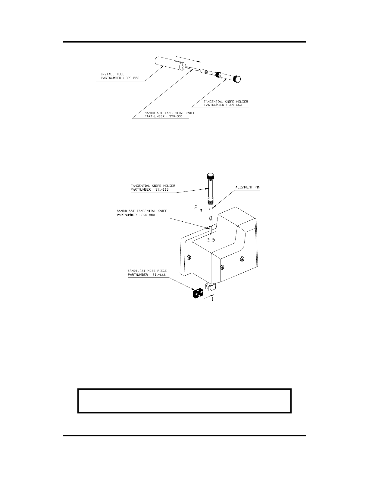
1. As shown in Figure 1 - 18, insert the knife blade into the knife holder. Make sure the knife blade
is firmly fixed into the holder. The blade is firmly fixed when you cannot remove it manually
from the knife holder. To remove the blade when it is too blunt, push at the back of the blade
with a screwdriver. The blade will jump out of its holder.
Page 39
User’s Manual SummaPaint PC1500
Operation 2-39
FIGURE 1 - 18
BLADE ASSEMBLY
2. Insert the black nose piece as shown in Figure 1 - 19 until it snaps into the nose piece holder.
When cutting masking stencil always replace the standard nose piece (grey colour) by the
masking stencil nose piece (black colour).
FIGURE 1 - 19
NOSE PIECE AND KNIFE INSTALLATION FOR CUTTING
MASKING STENCILS OR HEAVY MATERIALS
3. Gently insert the knife into the tool shaft as shown in Figure 1 - 19. Hold the nose piece in place
with one hand, with the other hand turn the knife holder anticlockwise until the alignment pin fits
into the small notch of the tool shaft. Then turn the knife holder clockwise until it g ets grip in th e
tool shaft.
4. For knife pressure and depth setting, refer to section 1.10.1.
NOTE
When cutting masking stencil or heavy materials, it can be necessary to lower
the cutting speed of the machine. Very heavy materials should be cu t at a sp eed
Page 40

User’s Manual SummaPaint PC1500
Operation 2-40
of 100 mm/s (4 ips) to get no overcurrent error caused by the drive motors.
To change the cutting speed, refer to paragraph 2.3.4.
Page 41
User’s Manual SummaPaint PC1500
Operation 2-41
INSTALLING A DRAG KNIFE
The SummaPaint PC1500 can also be operated with a DRAG knife. This feature requires a drag knife and
drag knife holder.
1. Remove the tangential knife by turning the knife holder anticlockwise with one hand while
holding the nose piece in place with the other hand.
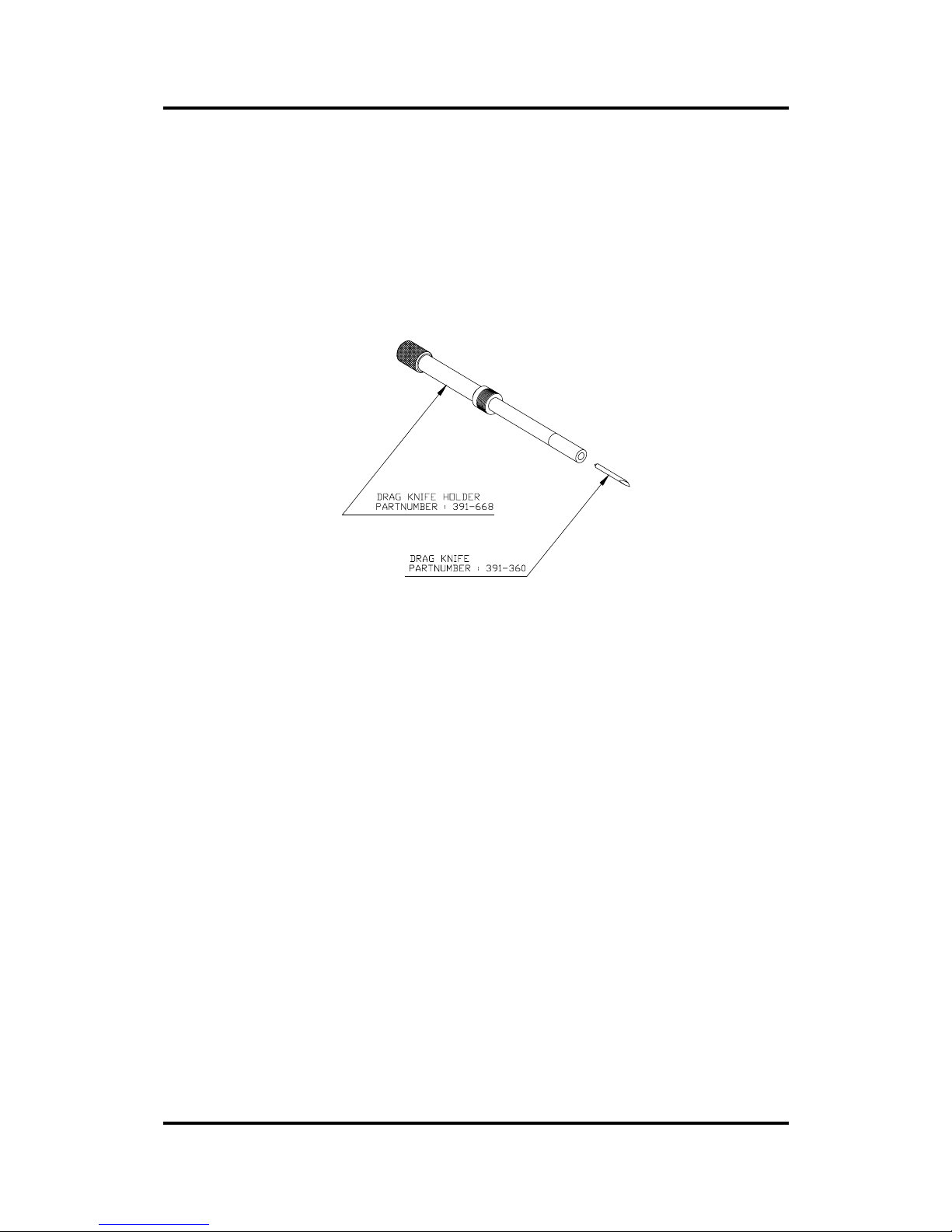
2. Insert the drag blade into the drag knife holder as shown in Figure 1 - 20.
FIGURE 1 - 20
DRAG KNIFE ASSEMBLY
3. Remove the nose piece (refer to Figure 1 - 21).
4. Insert the drag knife in the tool shaft as shown in Figure 1 - 21. Turn the drag knife holder
clockwise while holding the nose piece holder in place.
Page 42
User’s Manual SummaPaint PC1500
Operation 2-42
FIGURE 1 - 21
DRAG KNIFE HOLDER INSERTION
5. To configure the cutter for drag knife operation, press the key (tool select).
Then press the left or right jogging key until DRAG KNIFE appears on the second line of the
LCD .
Press ENTER and an asterisk will appear next to DRAG KNIFE. This indicates that the DRAG
KNIFE is selected. The drag knife will remain selected until another tool is selected or the cutter
is powered down. To start up the cutter in drag knife mode refer to section 2.4.5 (tool submenu
of the USER CONFIG MENU).
6. To set the pressure of the drag knife, refer to paragraph 1.10.1.
7. To set the knife offset, perform the knife offset test described in paragraph 2.3.3.
INSTALLING A BALLPOINT PEN
The SummaPaint PC1500 can also be operated with a BALL POINT pen. After replacing the knife with
a ball point pen, the cutter can be used as a plotter to draw draft plots of new or existing designs on paper.
Î To install the ball point pen, proceed as follows:
1. Remove the knife by turning the knife holder anticlockwise with one hand while holding the
nose piece in place with the other hand.
2. Remove the nose piece (refer to Fig 1-21).
3. Insert the ballpoint pen holder into the tool shaft as shown in Figure 1 - 22.
Page 43
User’s Manual SummaPaint PC1500
Operation 2-43
FIGURE 1 - 22
BALLPOINT PEN ASSEMBLY
4. In stall the ball-point pen as shown in Figure 1 - 23. Insert the ball point pen holder as far as
possible by turning it clockwise while holding the nose piece holder in place with the other hand.
FIGURE 1 - 23
BALLPOINT HOLDER INSERTION
5. To configure the cutter for ballpoint pen operation, press the key.
Press the left or right jogging key until BALLPOINT appears on the second line of the LCD .
Press ENTER and an asterisk will appear next to BALLPOINT, this indicates that the ballpo int
is selected.
A small P (for "Pen") will be displayed in the upper right corner of the LCD.
Page 44
User’s Manual SummaPaint PC1500
Operation 2-44
INSTALLING THE INK CARTRIDGES
NOTE
The cartridges will dry out quickly so it is advised to keep them in their or iginal
packaging until you’re ready to install them.
The service station prevents the drying out of the cartridges. However, if the
cartridges are not being used for more than 24 hours it is advisable to put the
cartridges back in a cartridges clamp. The cartridge clamps should be kept clean
by rinsing them with clean water each time they are used.
Each time one or more cartridges has been (re-)installed it is necessary to recalibrate the cartridges as described in section 2.
Cleaning of the cartridges is described in section 3.
To install an ink cartridges proceed as follows:
1. Turn on the unit. Make sure that the media i s properly loaded. Close
all tubes of the ink supply system by means of the clips nearby the
inkbottles.
2. When the unit is ‘Online’ press on the key. The print carriage will
move next to the service station. Every three seconds a beep will
warn you that the print carriage is not in the service station.
Clamp
Cartridge
Plug
FIGURE 1 - 24
INKCARTRIDGE AND CLAMP
CAUTION
Handle the cartridge with extreme care, because it is easily damaged.
Page 45
User’s Manual SummaPaint PC1500
Operation 2-45
3. If the cartri dge is filled with a transport fluid then first suck thi s out by
means of the syringe. Keep the cartridge in the clamp. If the
cartridges are filled with ink, skip this step.
FIGURE 1 - 25
INKCARTRIDGE BOTTOM VIEW
4. When the fluid is completely removed from the cartridge, remove
one of the two plugs that has the corresponding color from the print
carriage.
Plug
FIGURE 1 - 26
CONNECTING AN INK CARTRIDGE
NOTE
The unit is equipped with twice four tubes so that two different kinds of ink can
be used. To use the four bottles in the front, use the right connections of each
colour on the print carriage. To use the four bottles at the back, use the left
connections of each colour on the print carriage.
Page 46
User’s Manual SummaPaint PC1500
Operation 2-46
5. Connect the tube of the cartridge to the connector on the print-
carriage. Turn the tube a little counterclockwise before connecting
it clockwise so that the tube is not twisted while it’s being
connected.
6. Take the ink cartridge out of its clamp. Do not remove any protective
tape. Clean the copper contacts with a dampened soft lint free
cloth.
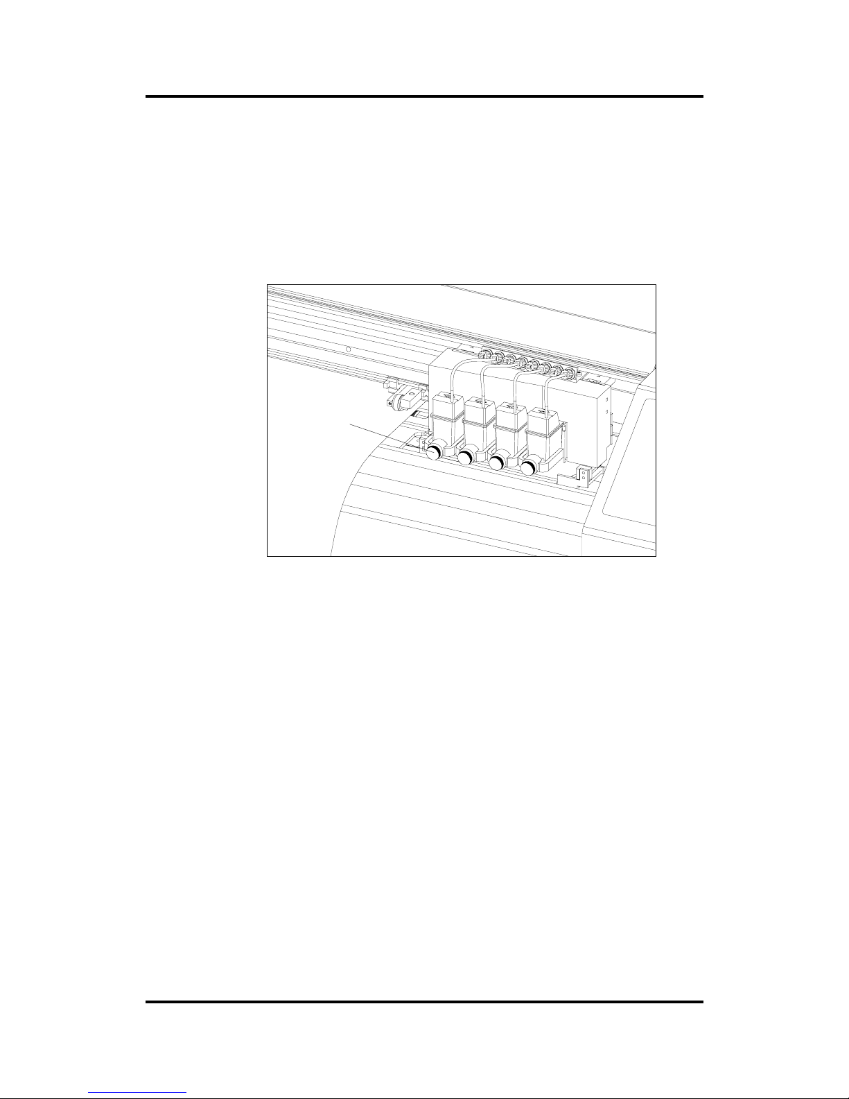
Thumbscre
w
FIGURE 1 - 27
INSTALLATION OF AN INK CARTRIDGE
7. Turn the thumbscrew on the carriage counterclockwise to make
space for the cartridge.
8. Hold the cartridge so that the arrow on top is pointing towards the
machine and insert it into the space.
9. Push the cartridge forward and hold it in position. Tighten the
thumbscrews clockwise. DO NOT OVERTIGHTEN THEM.
10. Follow steps 3 to 10 for the other cartridges.
11. Open the tubes by opening the clips.
12. Press on any key to move the print carriage back to the service
station.
Æ To remove a cartridge proceed in reverse order.
Page 47
User’s Manual SummaPaint PC1500
Operation 2-47
Inserting the ink
CAUTION
The ink can be harmful if swallowed. Keep the ink away from children. Wear
protective clothing and gloves when working with the ink.
NOTE
If the unit is not being used for a while it is advised to clean the tubes by
blowing the ink back into the bottles (See section 3 of the User Manual).
1. Power on the unit. Make sure that the media is properly loaded.
2. When the unit is ‘Online’ press on the key. The print carriage will
move next to the service station. Every three seconds a beep will
warn you that the print carriage is not in the service station.
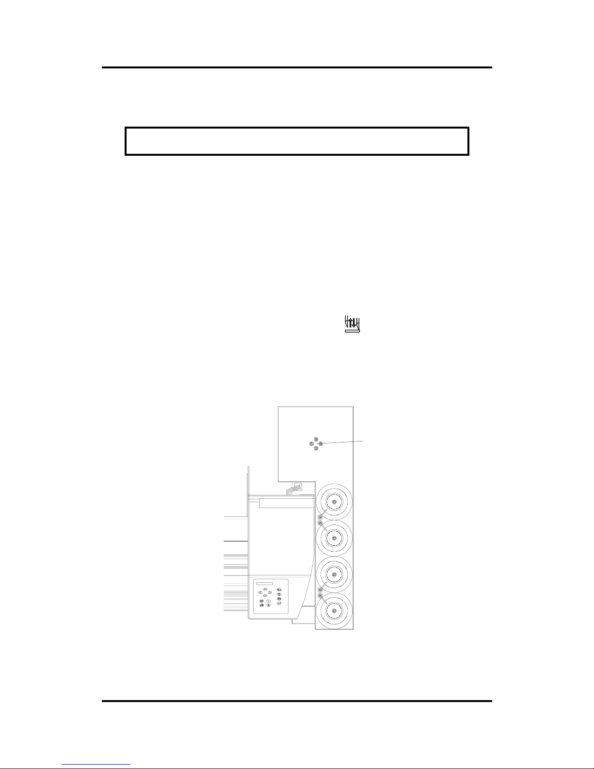
3. Remove the cap of the bottle of the inking system. Pour the
matching ink in the bottle and close it tight again.
Connections
for second set
Black
Cyan
Magenta
yellow
FIGURE 1 -28
POSITION OF THE INK BOTTLES
Page 48
User’s Manual SummaPaint PC1500
Operation 2-48
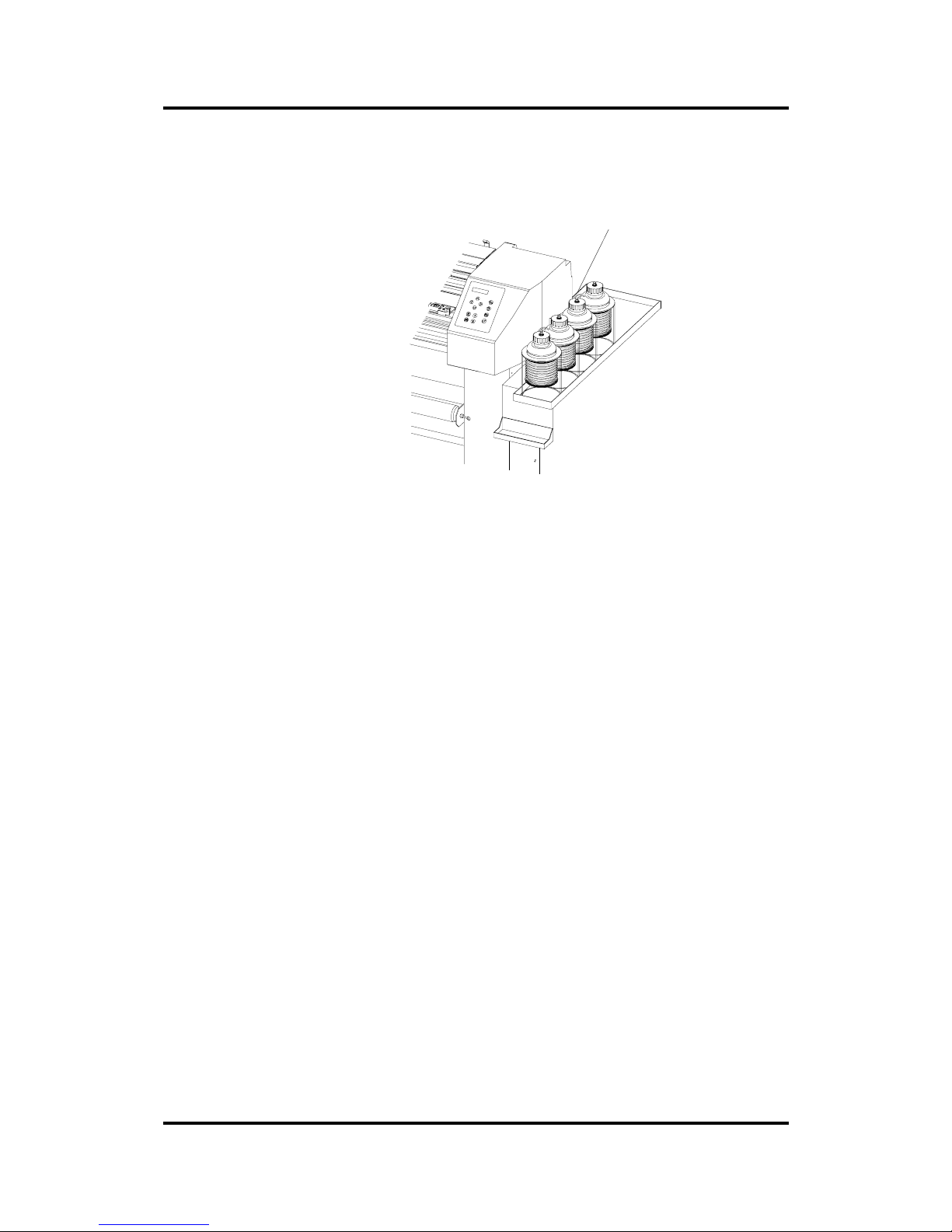
4. Connect the priming bulb on top of the bottle, and make sure that
the tube is open by opening the clip nearby the bottle.
clips
FIGURE 1 - 29
INK BOTTLES & CLIPS
5. Turn the knob on the carriage counterclockwise to loosen the
matching cartridge, and take the cartridge out of its holder. Make
sure that the tube of the cartridge is well connected to the print
carriage (see above).
6. Make sure that you have some absorbent paper within reach.
7. If the cartridge and the tubes have already been filled, proceed
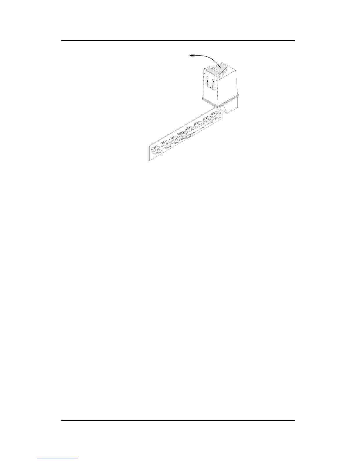
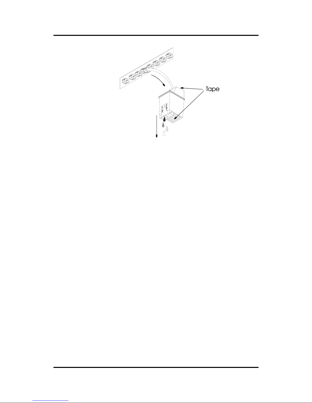
with step 9. If not, hold the cartridge upside down and remove the
tape as shown in Figure 1-30. (Do not remove the tape from the
nozzles.)
Page 49
User’s Manual SummaPaint PC1500
Operation 2-49
FIGURE 1 - 30
Filling the cartridge
8. Pump the ink through the tubes. When all the air is out of the tubes
and the cartridge is filled for at least 75 %, close the clip nearby the
bottle to stop the ink from flowing into the cartridge.
CAUTION
Pump gently! It takes some time before the ink flows through the tubes. Use soft
absorbent paper or soft lint free cloth to remove the outcoming ink.
9. Put a piece of adhesive tape on the bottom and on the top of the
cartridge (See Figure 1-31).
10. Hold the cartridge with the nozzles down above a reservoir. Remove
the protective tape on the nozzles and open the clip nearby the
bottle. Some air may appear in the tube. Pump some air in the inkt
bottle so that the ink starts leaking through the nozzles. As soon as all
the air is blown in the cartridge, close the clip nearby the bottle to
stop the ink from flowing to the cartridge. Remove the priming bulb
and open the clip again.
Page 50
User’s Manual SummaPaint PC1500
Operation 2-50
FIGURE 1 - 31
FILLING THE CARTRIDGE
11. Clean the nozzles and the copper contacts if needed. Never place
the cartridge in the print carriage when it is moistened with ink. The
ink can be removed with a dampened soft lint free cloth.
12. Hold the cartridge so that the arrow on top is pointing toward the
machine and place it back into the holder.
13. Push the cartridge forward and hold it in position. Tighten the
thumbscrew clockwise. DO NOT OVERTIGHTEN IT.
14. Follow steps 2 to 12 for the other colors.
15. Press any key to return the print carriage to the service station.
NOTE
To check whether all nozzles are working fine, perform the nozzle test (see section 2).
For further calibration of the cartridges, see Section 2.
Page 51
User’s Manual SummaPaint PC1500
Operation 2-51
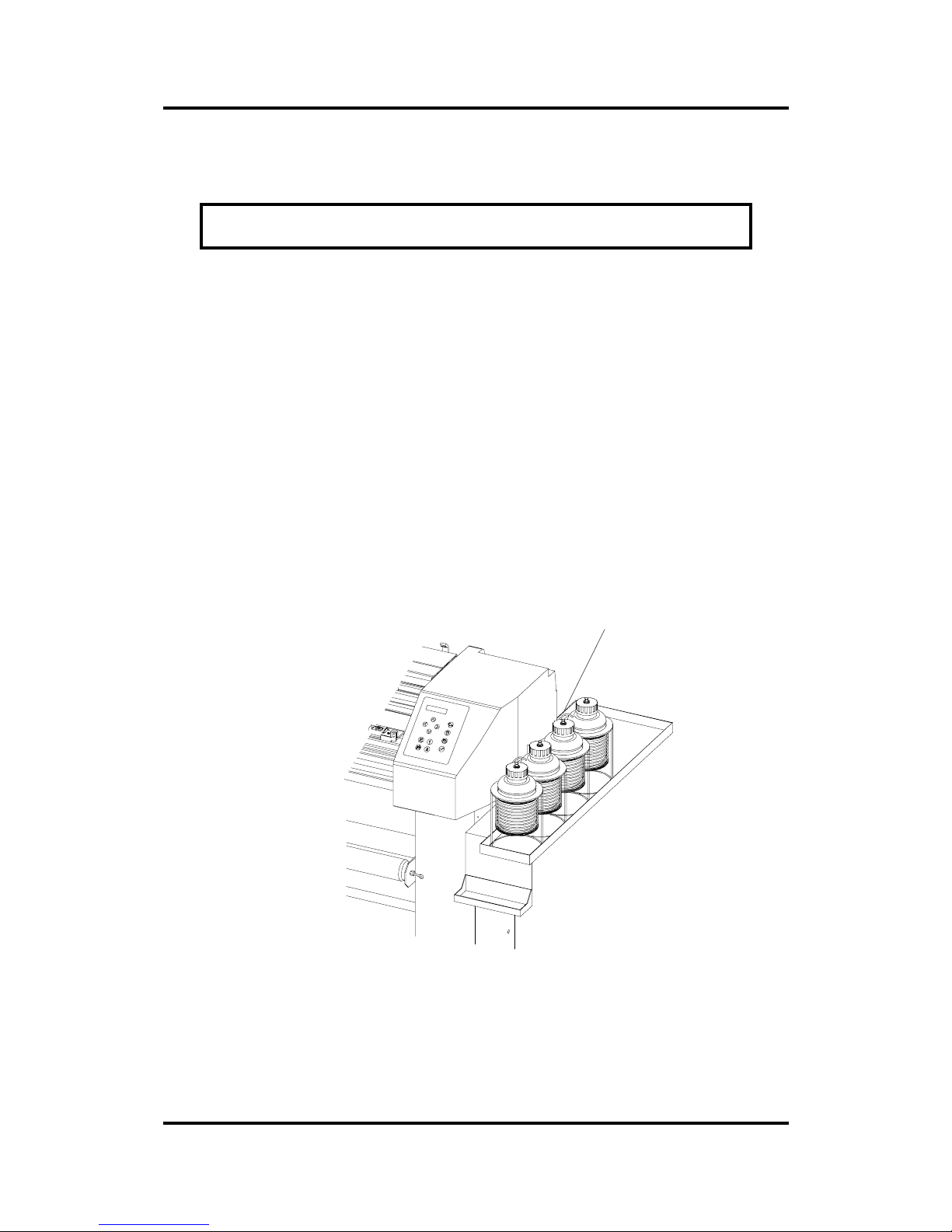
Refilling Ink
CAUTION
The ink can be harmful if swallowed. Keep the ink away from children. Wear
protective clothing and gloves when working with the ink.
NOTE
Make sure that the ink level in the bottles never goes below 1 cm (0.4”) in ord er
to prevent air-bubbles from coming in the tubes. Air-bubbles will cause
malfunctioning of the printer. When this problem occurs the “Inserting the ink”
section (1.12.) has to be repeated until all air-bubbles have disappeared.
Using the bottles until they are completely empty will cause the cartridges to
leak, which will result in the picture to be damaged.
Refilling the ink can simply be done as follows:
1. Refilling normally takes just a few minutes so that this can be done
while the printer is working.
clips
FIGURE 1 - 32
REFILLING INK
2. Remove the cap of the bottle of the inking system. Pour the
matching ink in the bottle and close it tight again.
Page 52

User’s Manual SummaPaint PC1500
Operation 2-52
PRINT & CUT
INTRODUCTION
Basically, there are two ways of contour cutting.
The first way is to print and cut the sign in one job. This means that the media
remains in the unit between the printing and cutting jobs. This process is
controlled by the drivers of specialized software, and no human interference is
required.
The other way of contour cutting allows the design to be printed on an other
unit, or to remove the design after printing from the SummaPaint for laminating.
In both cases the cutter must have the ability to locate the exact position of the
printed signs. Therefore, the SummaPaint is equipped with accurate alignment
methods to guarantee precise contour cutting. Depending on the selected
alignment method the SummaPaint is able to compensate for the following
issues:
1. If the printed design is not straightly loaded into the unit, the contour can be
rotated.
2. If the X and Y axes of the printed design are not exactly perpendicular, the
contour can be skewed.
3. If the print size is not correct, the contour can be scaled.
The parameter SPECIAL_LOAD in the user config. menu (see section 2)
determines which alignment method is used. These methods are based on the
principle of registration markers that are printed together with the drawing. For
the manual alignment methods these markers can be of any type. The
automatic method, however, requires the markers to be black squares so that
the sensor can detect them.
There are three manual alignment methods and one automatic alignment
method.
Manual alignment methods:
1. X-Axis Align : For this method, the origin and one point along the x-axis must
be specified. This method only rotates the contour. It does not require any
parameter.
2. XY-Axis Align : For this method, the origin, one point along the x-axis and one
point along the y-axis must be specified. This method rotates and skews the
drawing. It does not need any parameter.
3. XY-Adjustment : For this method, the origin, one defined point along the xaxis and one defined point along the y-axis must be specified. This method
rotates, skews and scales the drawing. It requires two parameters (x_distance
and y_distance). These distances define the position of the two points along
the axes (see further).
Page 53

User’s Manual SummaPaint PC1500
Operation 2-53
Æ When performing one of these three manual alignment methods, the display will prompt you to place
the knife tip on top of the registration markers. Try to do this with extreme accuracy because it
directly influences the precision of the contour cut.
Automatic alignment method:
1. OPOS : this is the automatic, and at the same time the most accurate
method. A more detailed description of this method can be found below.
General
NOTE
The OPOS system is automated in most of the Software that support the
SummaPaint PC1500. This means that the software takes care of the
registrations markers and the required parameters. Refer to the user manual of
your Software.
The manual alignment methods are simplified forms of the OPOS (optical positioning system). Therefore
the OPOS is explained below:
The OPOS sensor senses the printed markers around the printed design. From
the position of the markers the OPOS recalculates the lines to be cut so that
exact contour cutting can be done.
OPOS has the following concept:
• Create the design you want to perform the contour cut on
• Define the contour
• Place markers around your design, of which the sizes and distances are
known (depending of the alignment method that is chosen)
• Print out the design with the black markers
• Load the printed design in the cutter
• Set the parameter of the markers in the cutter
• Execute the special load procedure
• Cut out the contour
NOTE
If the OPOS does not work accurately it may be necessary to calibrate the
system (Section 2).
Page 54

User’s Manual SummaPaint PC1500
Operation 2-54
MARKER SPECIFICATIONS
In order to cut accurately on vinyl, the printed image must have markers over its whole length. The
markers should be black (on white vinyl) and positioned as shown in Figure 1-33. The markers should be
set at the same time and with the same print machine as the printed image, without removing the vinyl
between the marker and the image.
The x-axis is the paper direction, the y-axis is the axis along which the head of the cutter is moving.
If these parameters cannot be set in your software you can change them with SummaPaint Control
Software.
!
NOTE
The lower right corner of the lower right marker (= the origin-marker) must
determine the origin (0,0) of both the printed file and the cut file.
Page 55
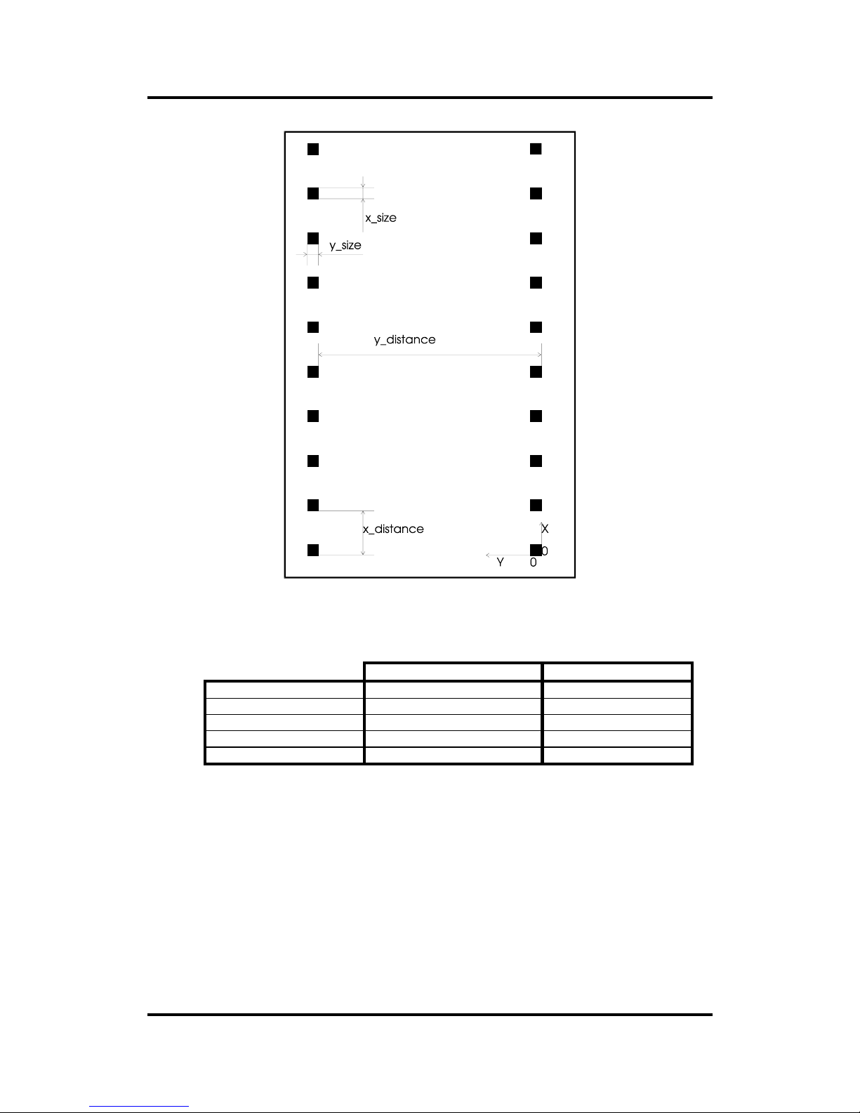
User’s Manual SummaPaint PC1500
Operation 2-55
FIGURE 1 - 33
MARKER SPECIFICATIONS
Default value Range
X_distance 60 mm 30 mm to 1300 mm
Y_distance 540 mm 30 mm to 1300 mm
x_size 1.5 mm 1.2 mm to 10 mm
y_size 1.5 mm 1.2 mm to 10 mm
markers quantity 14 2 to 64
Page 56
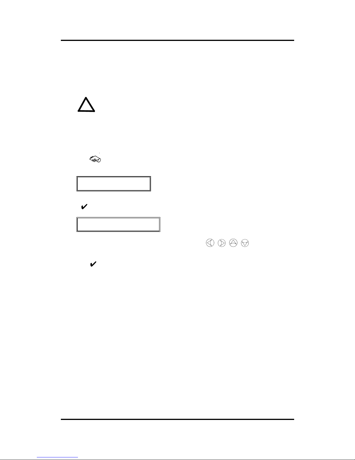
User’s Manual SummaPaint PC1500
Operation 2-56
CONTOUR CUTTING WITH OPOS
1. Before cutting the vinyl, the media must be loaded according to the loading procedure as described in
section 1.
!
NOTE
Place the vinyl in such a way that the marker representing the point of origin of
the drawing is situated in the front right.
2. Press the key until the message ‘SPECIAL LOAD’ is displayed on the LCD. (Note : Some
software is activating this command automatically. Then proceed with step 3).
SPECIAL LOAD
3. Press and the following message will appear on the LCD:
PLACE SENSOR ABOVE
LOWER RIGHT MARKER
4. Position the sensor exactly above the origin-marker using the ,
,
,
jogging keys,
Click the sensor box down manually.
Press the key to confirm the selected point of origin.
The cutter will now scan the markers and store the origin.
In case something may have gone wrong the following message will be displayed : ‘ ERROR:
MARKERS NOT SENSED PROPERLY’
5. Click up the sensor-box. You can now send the cut file with your usual application software for cutting
(e.g. WinCut or MacCut).
Page 57

User’s Manual SummaPaint PC1500
Operation 2-57
SECTION 2
OPERATION
1.1. SummaPaint control.
The SummaPaint Control Program for Windows is a tool to optimise the overall cutting and printing
quality of your PC1500.
For information on the installation or general set-up of this program, refer to the ‘Readme.txt’ file on the
installation disk.
The SummaPaint Control program basically has the same functions as the control panel. It is up to the
user to decide which way he will work most efficiently. The users who will work with the SummaPaint
Control program will notice that it is a very powerful and practical tool.
By clicking on the ‘Menu’ button in the main SummaPaint Control window all the machine settings can
be changed.
Four different user configurations can be saved in the cutter’s memory. The selected configuration
number is marked at the bottom of the menu window. These four configurations are maintained
independently.
1.2. THE CONTROL PANEL
Figure 2-1 shows the control panel of the SummaPaint PC1500. The main functions of the liquid crystal
display (LCD) and the control panel keys are explained in the following paragraphs.
Page 58

User’s Manual SummaPaint PC1500
Operation 2-58
FIGURE 2 - 1
SUMMAPAINT PC1500, CONTROL PANEL
1.3. The Liquid Crystal Display
The 32-character liquid crystal display (LCD) contains two lines of 16 characters each. The LCD
provides cutter status information during operations and displays menu options for the configuration of
the cutter.
The contrast of the LCD can be adjusted from the control panel in order to ensure optimum readability
under varying lighting conditions.
Instructions for adjusting the LCD contrast are given in Section 2.1.67.
The various menu and submenu items are always presented in a loop, which means that, when the last
menu or submenu item is displayed, pressing the appropriate key will automatically take you back to th e
first item of the same menu or submenu.
Next to the status messages and/or menu options displayed on the LCD, arrow symbols representing the
, , , jogging keys and the key will tell you which keys to press to go to the next
menu item (top line of the display) or to the next value for a given submenu item (bottom line of the
display).
1.4. THE RESET/LOAD Key
Page 59

User’s Manual SummaPaint PC1500
Operation 2-59
The key (RESET/LOAD) is used to move the origin, to initiate a load sequence, to reset the
machine or to abort the job in progress. When the
key (RESET/LOAD) is pressed, the unit goes off
line, suspends all operations in progress and displays the RESET/LOAD menu. Press the
key until
SET ORIGIN, LOAD, RESET, ABORT or SPECIAL LOAD is displayed. To confirm RESET, ABORT
or SPECIAL LOAD press the
key (ENTER). To execute the SET ORIGIN instruction move the
knife origin using the , , , jogging keys and press the key (ENTER) to confirm the
new origin position. To initiate the LOAD instruction press the 1 or 2 key to initiate a load sequence for a
ROLL or SHEET respectively. Upon termination of any of these instructions, the cutter goes on line
again.
The SET ORIGIN instruction is used to move the knife origin.
The LOAD instruction is used to initiate a load sequence.
The RESET instruction performs a complete reset of the cutter.
The ABORT instruction simply cancels the cut in progress. Aborting a cut will not reset the cutter
parameters: the parameters which had been selected for the cut remain in effect.
The SPECIAL LOAD instruction activates the OPOS system (see Section 1).
1.5. The ON LINE Key
The key (ON LINE) toggles between on line and off line operation. When the key is pressed, the
selected mode (ON LINE or OFF LINE) is displayed on the LCD.
Selecting OFF LINE will suspend all operations in progress. Pressing the key while the cutter is off
line will make the machine go on line again, resuming the suspended operation.
Page 60
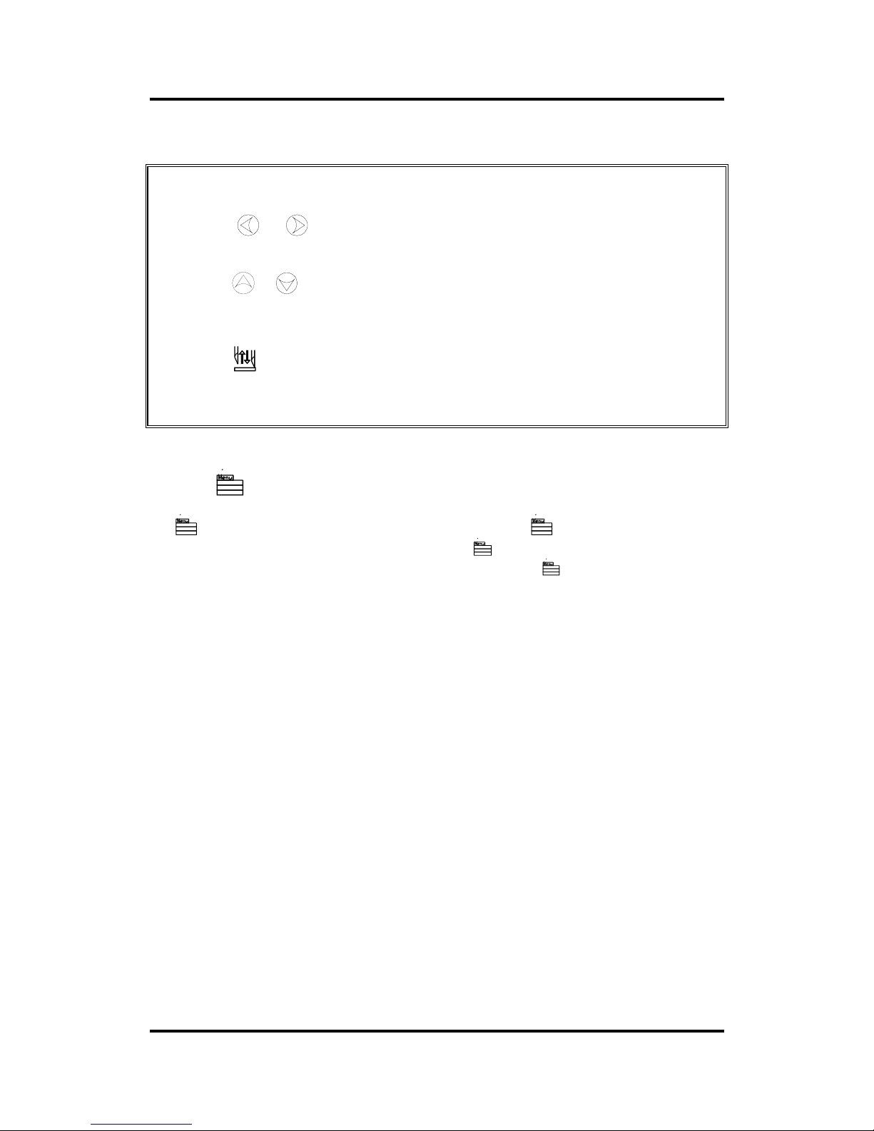
User’s Manual SummaPaint PC1500
Operation 2-60
While the machine is off line, the following operations can be performed:
• Press the or jogging key to move the tool carriage to the left or right.
(disabled in printing mode)
• Press the or jogging key to make the media move forward (towards you) or
backward (away from you). Moving the media forward will prove to be very
practical when you require to cut the finished sign off manually.
• Press the key (TOOL UP/DOWN) to lower or raise the active tool of the cutting
head. If the tool is not moved for approximately eight seconds, it is raised
automatically (disabled in printing mode).
1.6. The MENU Key
The key (MENU) is used to select one of the menus. Pressing the key will make the cutter go off
line and suspend all operations in progress. Pressing the
key repeatedly will display the different
menus one by one. As the menu options are on a loop, pressing the
key when the last option is
displayed will automatically return you to the first option.
The different menus are illustrated in Figure 2-2.
Page 61
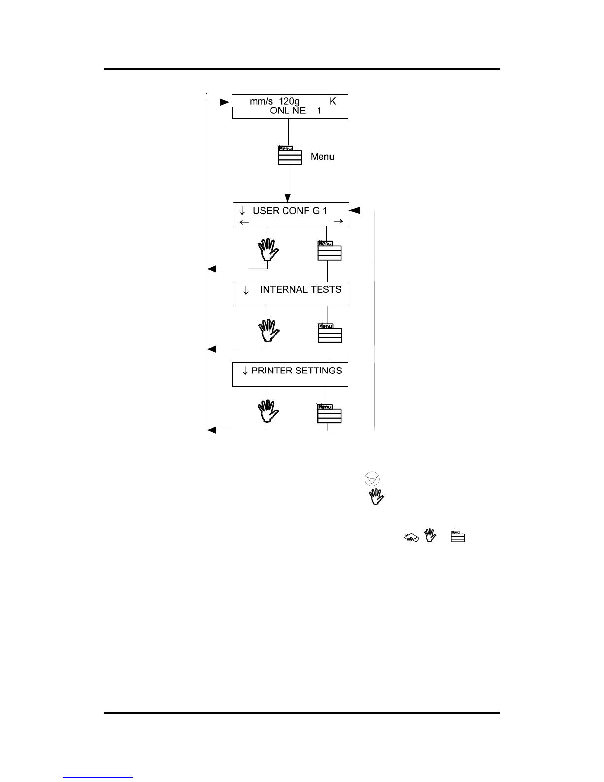
User’s Manual SummaPaint PC1500
Operation 2-61
500
FIGURE 2 - 2
SUMMAPAINT PC1500, CONFIGURATION SUBMENUS
To select a menu by scrolling through the different options, press the jogging key .
To exit the menus and resume the previous on line operation, press the key (ON LINE).
Under normal conditions, the machine is on line; it may then be selected by the host computer for a
printing or cutting operation or deselected by the host computer. Pressing the
, or key will
make the cutter go off line, in order to initiate another operation.
The contents of the different menus are summarised in Table 2-1.
Page 62
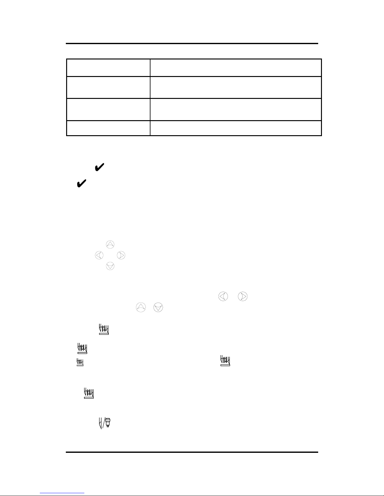
User’s Manual SummaPaint PC1500
Operation 2-62
MENU DESCRIPTION
USER CONFIG 1 (->4)
Selects a given active cutter configuration from one of the four sets
of configuration parameters stored in the unit's memory
INTERNAL TEST
Activates one of the resident cutting plots provided for informational
purposes.
PRINTER SETTINGS
Activates the internal printing tests and printing parameters
TABLE 2-1:
CONTENTS OF THE SUMMAPAINT PC1500 MENUS
1.7. The ENTER Key
The key (ENTER) is used to select the item currently displayed on the LCD.
1.8. 1 2 The 1 and 2 Keys
The use of the 1 and 2 keys varies according to the operation in progress; their use is displayed on the
LCD as appropriate.
1.9. The Jogging Keys
The use of the jogging keys varies according to the operation in progress.
For example, when working in the USER CONFIG menu, the or jogging key is used to select
the new user number and the
or jogging key is used to go to the previous or next menu item.
1.10. The TOOL UP/DOWN Key
The key (TOOL UP/DOWN) is used while the cutter is off line to raise or lower the tool. Pressing
the
key once will lower the tool onto the media. Pressing the k e y again will raise the tool.
If the tool is not moved for approximately eight seconds, it is raised automatically. (This key is disabled
in print mode)
If the key is pressed while the unit is online, the print carriage will move just beside the service
station. Pressing any key will move the print carriage back.
1.11. THe tool select key
Page 63

User’s Manual SummaPaint PC1500
Operation 2-63
The key (TOOL SELECT) is used to select one of the following tools :
a tangential knife
a drag knife
a ballpoint pen
To temporarily change the tool, press the key, then press the or jogging key until the
desired tool appears on the second line o the LCD. Press the
key to conf irm the tool. An asterisk *
appears next to the selected tool. When the cutter is powered on the next time, the default tool will be
selected. For setting up the default tool see Section 2.1.27.
Page 64

User’s Manual SummaPaint PC1500
Operation 2-64
1.12. NORMAL OPERATION
The term "normal operation" covers on line operation, off line operation and local operation, i.e. the three
types of operation for actual cutting or plotting. They are explained in further detail in the following
paragraphs.
1.13. On line and Off line
On line and off line are two important concepts when using the SummaPaint PC1500. The cutter is on
line only when one of the following messages is displayed on the LCD :
Online in cutting mode:
500mm/s 120 g K
.45mm(1) *ON LINE 1
This display message should be read as follows
:
500 mm/s = velocity
120 g = knife pressure or pen
pressure
K = knife operation (K) or
pen operation (P)
.45 mm(1) = knife offset - only
displayed when in
drag knife mode
*ON LINE = cutter is ready to
receive data
1 = user number
Online in printing mode:
PRINT MODE K
*ON LINE 1
This display message should be read as follows
:
PRINT MODE = indicates that the
machine is in print mode.
K = knife operation (K) or
pen operation (P)
*ON LINE = printer is ready to
receive data
1 = user number
Page 65
User’s Manual SummaPaint PC1500
Operation 2-65
In all other cases, the cutter is off line.
When on line, the cutter can be addressed by the host computer, which means that the cutter will execute
cutting or plotting instructions issued by the host computer's application software.
For normal operations, the cutter MUST be on line, so that it can receive instructions from the host
computer and the printing/cutting software.
When the machine is on line, the following conditions must be met:
• The cutter must be powered ON.
• Media must be loaded. For detailed media loading instructions, see Section 1.8 .
• The proper tool must be installed .
• The unit must be connected to the host computer via the parallel interface and / or
the RS-232-C link.
• The unit must be configured for the scheduled operation.
To put the cutter off line, press the , or key. Pressing any of these keys will suspend the
current cutting operation until the PC1500 is put on line ag ain. Pressing
the key will suspend the
current printing operation until the PC1500 is put online again.
1.14. Local operation
Local operation is only possible while the machine is off line. Local operation means that the machine is
operated directly by the operator via instructions entered on the control panel.
Î To work in local operation mode, proceed as follows:
1. If the machine is still on line, press the key once to select off line. The media will
move forward over a certain distance.
2. To move the carriage to the left or right, press the or jogging key. (Disabled in
print mode)
3. To make the media move forwards (towards you) or backwards (away from you),
press the
or jogging key.
4. To move the tool head up or down, press the key. (Disabled in print mode)
5. To end local mode and put the cutter on line again, press the key.
Page 66

User’s Manual SummaPaint PC1500
Operation 2-66
1.15. THE USER CONFIG MENU
The USER CONFIG(uration) menu gives access to different submenus which allow you to configure the
cutter's operating parameters. It should be taken into account that access to some of the submenus will be
determined by the plotting language you are using.
Four different user configurations can be saved. The selected configuration number is displayed on the
LCD next to the USER CONFIG message. These four USER CONFIG 1(->4) menus are maintained
independently.
Î To select another configuration number, proceed as follows:
1. Power on the cutter.
2. Press the key until USER CONFIG 1(->4) is displayed.
3. Press the or jogging key until the desired configuration number is displayed
next to USER CONFIG.
NOTE
Before altering any of the items in the USER CONFIG menu, make sure that
you have previously selected the right configuration number in the USER
CONFIG 1(->4) menu.
Figure 2-3 shows the USER CONFIG submenus.
Î To select and alter a configuration parameter, proceed as follows:
1. Power on the cutter.
2. Press the key until USER CONFIG 1(->4) is displayed.
3. Press the, or jogging key until the desired submenu is displayed on the first
line of the LCD.
4. Press the or jogging key until the desired value is displayed on the second line.
5. Press the ke y to confirm the selection, an * will be displayed next to the selected setting. (An
* is always displayed next to the active value. )
Page 67
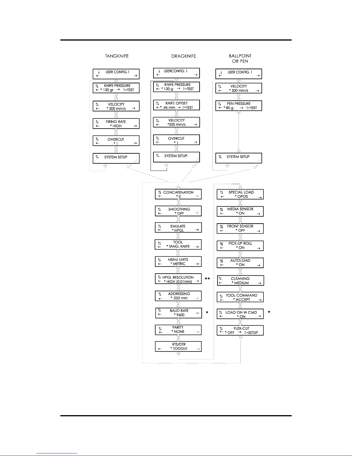
User’s Manual SummaPaint PC1500
Operation 2-67
* = in DM/PL ONLY
** = IN HP-GL and HP-GL/2 ONLY
FIGURE 2 - 3
FLOWCHART SHOWING FACTORY PRESET MENU SETTINGS
Page 68

User’s Manual SummaPaint PC1500
Operation 2-68
1.16. KNIFE PRESSURE
The KNIFE PRESSURE submenu is used to set or modify the cutting pressure of the knife.
The default knife pressure value is 120 grams.
The knife pressure can be set between 0 and 600 grams.
The knife pressure value is set in 5 gram increments.
On the LCD, the active knife pressure value is marked with an *.
Knife pressure setup is explained in detail in section 1.
1.17. PEN PRESSURE
The PEN PRESSURE submenu is used to set or modify the pressure of the ball point pen.
The default ball point pressure value is 80 grams.
The pressure can be set between 0 and 600 grams in 5 gram increments.
On the LCD, the active pen pressure value is marked with an *.
1.18. KNIFE OFFSET
The KNIFE OFFSET submenu is used to set or modify the distance between the DRAG knife blade tip
and the centre axis. This routine applies to a drag knife only.
The default drag knife offset value is .45 mm.
The value can be set between 0 and 1 mm.
Make sure that the selected knife offset value matches that of the knife. Some fine tuning may be
necessary because of the mechanical tolerances on the knife. To verify the knife offset, a test can be cut
by pressing the 1 key.
If the offset value is set too low, the rectangles will not close.
When the offset value is set too high, the rectangles will be distorted.
The offset test is illustrated below.
1.19. FIRING RATE
The firing rate submenu is used to set the speed of printing. When using ink types with a high viscosity it
is advised to lower the firing rate to obtain a better print quality and a longer life time of the ink
cartridges. Lowering the firing increases the time of printing.
The default firing rate is high.
The firing rate can be set to LOW, MEDIUM and High.
1.20. VELOCITY
The VELOCITY submenu is used to set or modify the velocity of the tool.
The default velocity is 500 mm/s (20 ips).
The velocity can be set between 50 mm/s (2 ips) and 600 mm/s (24 ips).
1.21. OVERCUT
The OVERCUT submenu enables you to generate an overcut in order to facilitate weeding the cut.
Page 69

User’s Manual SummaPaint PC1500
Operation 2-69
The default overcut is set to 1.
The overcut setting can be disabled (=0) or set to any value between 0(=off) and 10. One unit is about 0.1
mm or 0.004 ".
On the LCD, the active value is marked with an *.
1.22. SYSTEM SETUP
The SYSTEM SETUP submenu covers the menu items you normally only need when establishing the
initial setup e.g. when you install the cutter in combination with the software you use.
Press the key to access the different submenu items, which are explained in section 2.4.
Page 70

User’s Manual SummaPaint PC1500
Operation 2-70
1.23. SYSTEM SET UP
Refer to Figure 2-3.
1.24. CONCATENATION
The CONCATENATION feature increases the speed and quality with which cut data having a very high
resolution is cut. However when changing over to normal characters again, deactivate concatenation by
setting this parameter to 0.
On the LCD, the active concatenation value is marked with an *.
1.25. SMOOTHING
The SMOOTHING feature helps to cut smoother curves when curve data with many short vectors is
received from the computer.
The default setting is OFF.
On the LCD, the active setting is marked with an *.
1.26. EMULATE
The EMULATE submenu is used to select the active cutting/plotting language for the cutter.
The SummaPaint PC1500 supports HP-GL, HP-GL/2 and DM/PL.
On the LCD, the active plotting language setting is marked with an *.
NOTE
The active cutting/plotting language MUST match the cutting software.
Always select a language which is supported by the host computer's cutting
software.
Select the HP-GL menu option to set the active cutting/plotting language to HP-GL. The cutter will
emulate an HP model 758xB plotter (with selectable origin, see 2.4.12).
Select the DM/PL menu option to set the active cutting/plotting language to Houston Instrument Digital
Microprocessor/Plotting Language (DM/PL). This selection will allow the cutter to operate with DM/PLbased cutting / plotting software. This language, having sp ecial command extensions for cutting, normally
gives superior cutting performance.
1.27. TOOL
The TOOL sub-menu is used to select the default tool at power up.
To configure the cutter for TANGENTIAL KNIFE cutting operations, select the TANG. KNIFE option.
To configure the cutter for PLOTTING operations, select the BALL POINT option.
To configure the cutter for DRAG KNIFE cutting operations, select the DRAG KNIFE option.
To select a tool other than the default one temporarily, see section 2.1.11.
1.28. MENU UNITS
Page 71

User’s Manual SummaPaint PC1500
Operation 2-71
The MENU UNITS submenu allows you to select English or metric menu units for DM/PL.
For models sold in the US, English units are the default setting.
For models sold in Europe, metric units are the default setting.
On the LCD, the active menu units setting is marked with an *.
1.29. HPGL RESOLUTION
The HPGL RESOLUTION sub-menu is used to select the cutter's default HPGL user-addressable cutting
resolution.
The default addressing resolution is HIGH (0.01 mm) .
The user-addressable resolution can be set to NORMAL (0.025 mm) or HIGH (0.01 mm).
On the LCD, the active resolution value is marked with an *
1.30. ADDRESSING
The ADDRESSING submenu is used to select the cutter's default DM/PL user-addressable cutting
resolution.
The default addressing resolution is 0.025 mm (Europe) or 0.001" (US).
The user-addressable resolution can be set to 0.025 mm or 0.001" or 0.1 mm or 0.005".
On the LCD, the active resolution value is marked with an *
1.31. BAUD RATE
The BAUD RATE submenu is used to set or modify the operating baud rate for RS-232-C serial
communications between your cutter and the host computer.
The default baud rate is 9600 bps.
The baud rate can be set to any of the following values: 2400 bps, 4800 bps, 9600 bps, 19200 and 38400
bps.
On the LCD, the active baud rate value is marked with an *.
NOTE
The baud rate setting of your cutter MUST match the host computer's baud
rate setting.
1.32. PARITY
The PARITY sub-menu is used to set or modify the byte format and parity type for RS-232-C serial
communications between your cutter and the host computer.
The default parity setting is bit 8 = 0 (8 data bits, no parity, the 8th bit b eing a low bit). The parity can be
set to any of the following values:
LCD information Parity setting Remarks
NONE
8 data bits, no parity bit 8 = low (0)
MARK
8 data bits, no parity bit 8 = high (1)
EVEN
7 data bits, 1 parity bit parity bit = even
ODD
7 data bits, 1 parity bit parity bit = odd
On the LCD, the active parity setting is marked with an *.
Page 72

User’s Manual SummaPaint PC1500
Operation 2-72
NOTE
The parity setting of your cutter MUST match the host computer's parity
setting.
1.33. RTS/DTR
The RTS/DTR submenu controls the Request To Send (RTS) and Data Terminal Ready (DTR) signals of
the cutter's RS-232-C serial communications interface for hardw are handshaking.
The RTS/DTR default value is TOGGLE.
RTS/DTR can be set to TOGGLE (hardware handshaking) or HIGH (software handshaking).
On the LCD, the active handshaking setting is marked with an *.
1.34. special load
The special load submenu is used to determine which alignment procedure is used when activating the
special load procedure (see section 1). By using the the special load procedure, a contour cut can be done
on a preprinted sign. On the LCD the active value is marked with an *.
The default setting is OPOS.
The SPECIAL LOAD can be set to X-AXIS ALIGN, XY-AXIS ALIGN, XY-ADJUSTMENT and
OPOS.
1.35. MEDIA SENSOR
The MEDIA SENSOR sub-menu is used to activate or deactivate the media sensors. On the LCD, the
active setting is marked with an *.
The sensors detect whether media is loaded or detect the end of media. The sensors prevent damage to the
cutting strip and knife tip.
1.36. Front sensor
The FRONT SENSOR sub-menu is used to activate or deactivate the front media sensors. On the LCD,
the active setting is marked with an *.
The front sensors detects the front edge of the media. Disabling the front sensors prevents that the media
is pulled back in the loading sequence. This is necessary when the pick-up roll is used.
1.37. PICK-UP ROLL
The PICK-UP ROLL sub-menu is used to activate or deactivate the pick-up roll. When using sheets or
when you simply do not want to use the pick-up roll you can switch it off. The default setting is ON.
On the LCD display, the active setting is marked with an *.
1.38. autoload
The AUTOLOAD option enables the user to the change the vinyl unroll proceedings. When
AUTOLOAD is ON , the PC1500 will automatically unroll the media when needed. When the
AUTOLOAD option is OFF, the operator himself should unroll enough media before starting to cut.
The default setting is ON. Best results and performance are usually guaranteed when using this setting.
On the LCD display, the active setting is marked with
Page 73

User’s Manual SummaPaint PC1500
Operation 2-73
an *. When using weak or soft materials, e.g. canvas, better results are achieved when autoload is off.
Page 74

User’s Manual SummaPaint PC1500
Operation 2-74
1.39. cleaning
The CLEANING sub-menu is used to set the cleaning frequency of the cleaning procedure.
While printing, the print carriage moves periodically to the service station to clean the print heads and to
spit some ink out of all its nozzles to prevent the nozzles from blocking. It is advised to set the cleaning as
low as possible to work faster and save ink. In this way the reservoirs of the service station can be used
longer before they need to be cleaned (see section 3).
However, if the cleaning frequency is too low, the nozzles will block.
The default setting is MEDIUM.
Cleaning can be set to OFF, LOW, MEDIUM and HIGH.
1.40. TOOL COMMAND
The TOOL COMMAND is used to determine whether the DM/PL and HP-GL pen/knife-select
commands (the P and SP commands respectively) are ignored or accepted.
When the TOOL COMMAND option is set to “ACCEPT”, the P or SP commands will change the
selected tool in the cutter according to the suffix that follows the pen/knife command. The cutter’s LCD
will, e.g. prompt the user with the following message: “INSERT PEN” when a P2 command is sent.
When the TOOL COMMAND option is set to “IGNORE”, the pen/knife commands are ignored.
On the LCD, the active setting is marked with an *. The default setting is “ACCEPT”.
1.41. LOAD ON W COMMAND
The LOAD ON W CMD submenu will only be displayed if the PLOT LANGUAGE is set to DM/PL (See
Paragraph 2.1.26.). The LOAD ON W CMD determines, when receiving the DM/PL Window-command
(W-command), whether aside from the scaling function, media is loaded or not. Besides scaling, the Wcommand is also very useful when cutting long signs. With the W-command, media loading will go
smoother. Sufficient media will be pulled off the roll at once. Even when AUTOLOAD is off, there is no
need anymore to unroll the media manually.
1.42. FLEX-CUT
FLEX-CUT can be set to OFF, to Mode 1 or Mode 2. When the cutter is set to mode 1 or mode 2, it will
alternately cut one length with full pressure, and one length with reduced pressure. The feature FLEXCUT offers the advantage that it cuts completely through the material, yet allowing the material to stay
together by means of the small media bridges.
MODE 1 is the quickest mode, but it is less precise because the pressure changes during the cutting.
MODE 2 is a lot slower, but at the same time it is much more precise, as the cutter stops at every change
of pressure. Pressing the
1 key will activate the configur ation menu, which allows you to set the cutting
pressure and the cut length.
1. CUT LENGTH
This parameter determines the length that is cut with full pressure. By pressing the 1 key, the FLEX-CUT
test pattern will be cut.
2. FLEX-CUT LENGTH
This parameter determines the length that will be cut with reduced pressure or without pressure. By
pressing the
1 key, the FLEX-CUT pattern will be cut.
3. FLEX PRESSURE
Page 75

User’s Manual SummaPaint PC1500
Operation 2-75
This parameter determines the pressure of the FLEX-CUT LENGTH. By pressing the 1 key, the FLEXCUT test pattern is cut.
Page 76

User’s Manual SummaPaint PC1500
Operation 2-76
1.43. INTERNAL TEST MENU
Î To access any internal test, proceed as follows:
1. Power the machine on.
2. Load cutting or printing media.
3. Install a knife or a pen.
4. Press the key until INTERNAL TEST is displayed and press the jogging key.
5. Press the or jogging key until the desired internal test is displayed.
6. To perform the test, press the key.
To exit from this menu and go to another menu, press the key until the desired menu is displayed.
To exit from the menus and put the cutter on line again, press the key.
Figure 2 - 4 shows the different INTERNAL TEST subme nus.
Page 77
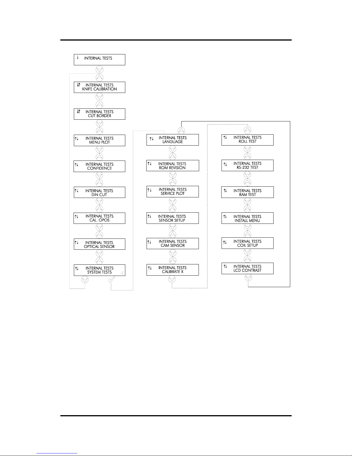
User’s Manual SummaPaint PC1500
Operation 2-77
FIGURE 2 - 4
INTERNAL TESTS SUBMENUS
1.44. TANG. KNIFE CALIBRATION
The purpose of the knife calibration routine is to detect and, if need be, to correct problems related with
the concentricity of the TANGENTIAL knife blade. This routine should only be run when required.
When noticing cut quality problems with a new knife, pe rform a knife calibration test as described in the
following paragraphs.
During the knife calibration routine, the cutter will cut a series of test patterns which will allow you to
identify errors in knife rotation and concentricity. Corrective measures can be taken using the control
panel keys.
Knife calibration errors may be due to any of the following causes (see Fig. 2-5):
Page 78
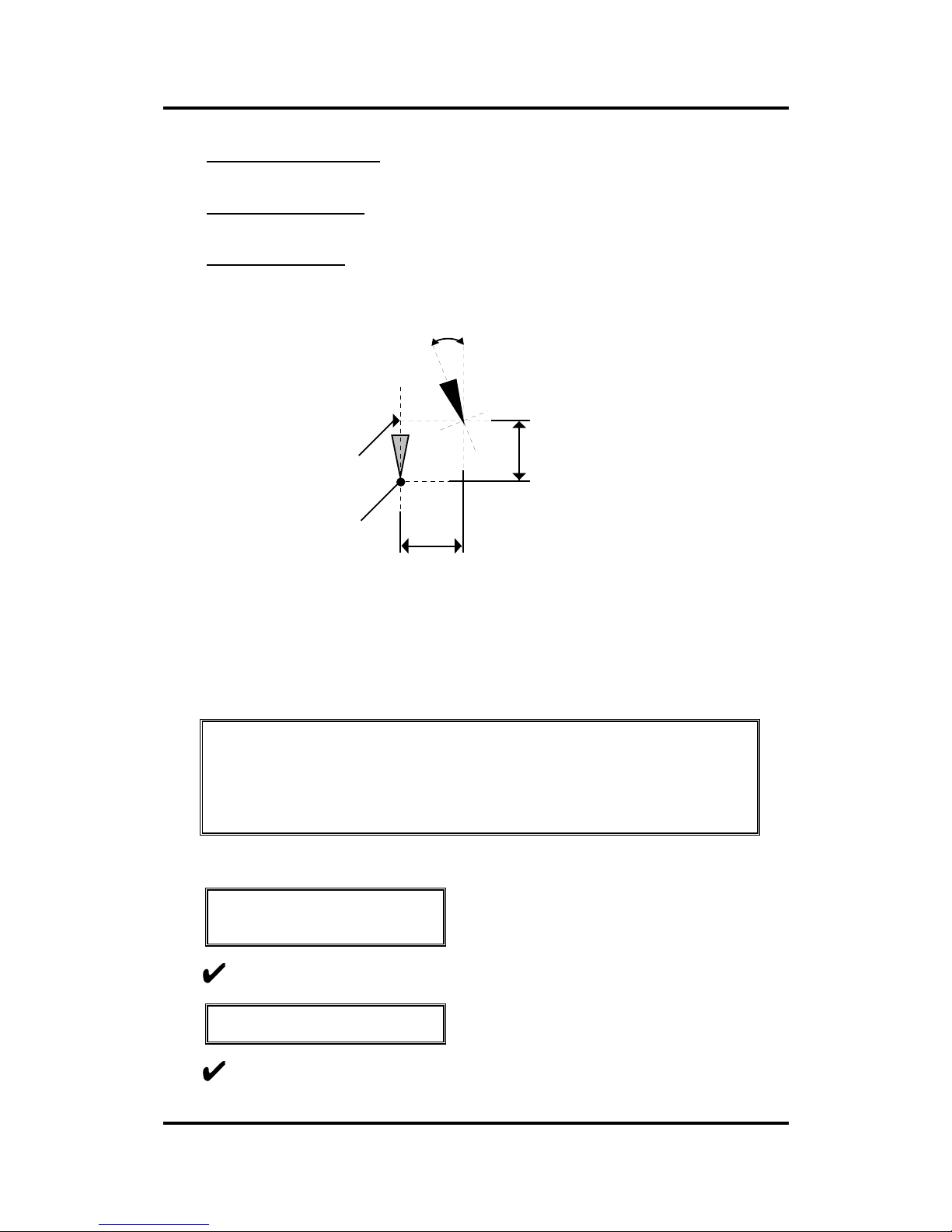
User’s Manual SummaPaint PC1500
Operation 2-78
• Concentricity misalignment. The knife tip is slightly rotated in relation to its theoretical 0° angle.
This error can be corrected by means of the ADJUST ORIGIN test routine.
• Horizontal misalignment. The knife tip deviates from its theoretical longitudinal centre. This
error can be corrected by means of the ADJUST LONG. test routine.
• Vertical misalignment. The knife tip deviates from its theoretical lateral centre. This error can be
corrected by means of the ADJUST LAT. test routine.
LONGITUDINAL deviation
LATERAL deviation
Theoretical centre
of the knife
Theoretical 0º
angle of the knife
ORIGIN deviation
FIGURE 2 - 5
POSSIBLE KNIFE CALIBRATION GROUNDS
The calibration settings entered during the knife calibration routine are automatically stored in the
machine’s memory and will be maintained after power down.
NOTE
Prior to knife calibration, load vinyl and install a knife to avoid damage to
the cutting strip.
1.45. ADJUST ORIGIN test routine
↓ INTERNAL TESTS
↑ CALIBRATE KNIFE
Press to select the ORIGIN test.
ADJUST ORIGIN
↑↓ 0
Press to execute the ORIGIN test.
Page 79
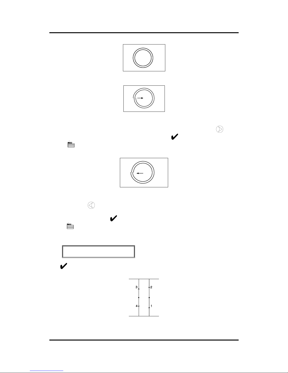
User’s Manual SummaPaint PC1500
Operation 2-79
This is the correctly cut test pattern.
Weed out the ring and compare the circle pattern cut in the vinyl with the circle pattern illustrated above.
If you obtained this kind of pattern, increase the value displayed on the LCD by pressing the
jogging
key to correct closing of the circles cut. To repeat the test, press the
key.
Press the key to go to the next step of the calibration procedure
However if you obtained the kind of pattern illustrated above, then, decrease the value displayed on the
LCD by pressing the
jogging key to correct closing of the circles cut.
To repeat the test, press the key.
Press the key to go to the next step of the calibration procedure
1.46. ADJUST LAT. TEST ROUTINE
ADJUST LAT
↑↓ 0
1
Press to execute the LAT test.
1 runs from the horizontal line at the bottom to the centre.
2 runs from the horizontal line at the top to t he centre.
Page 80
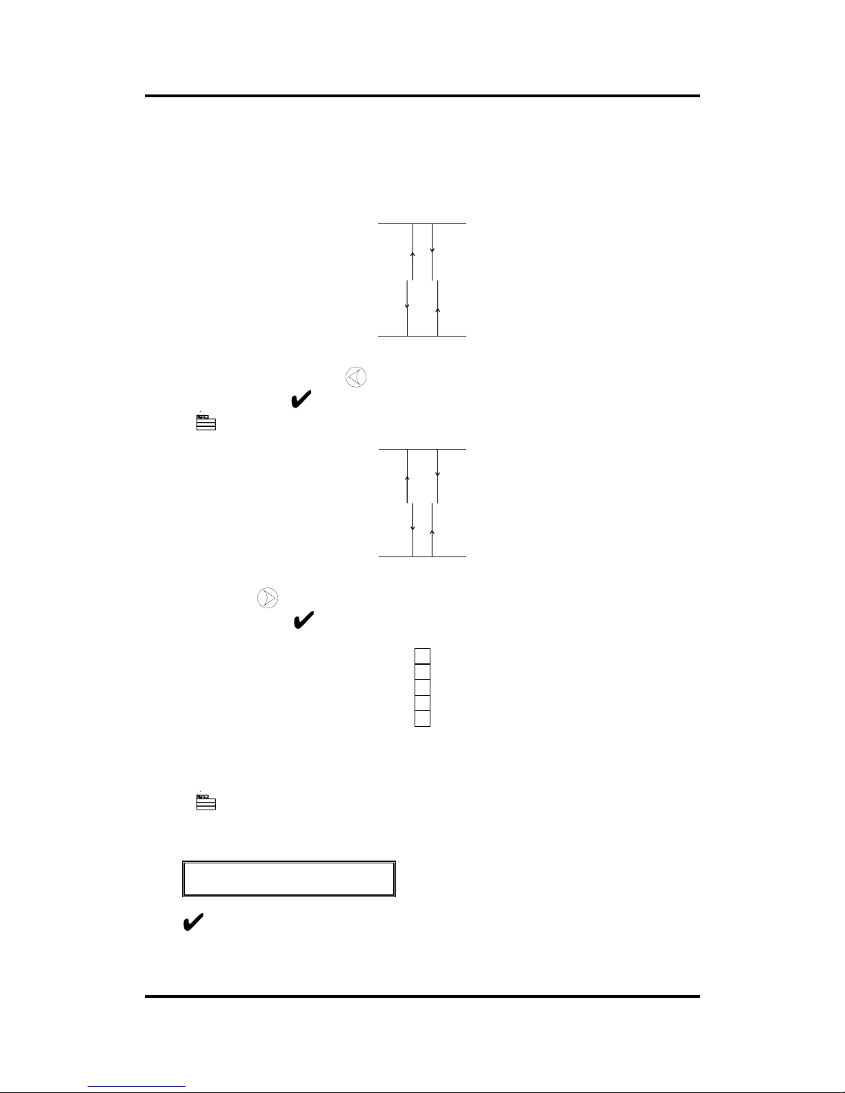
User’s Manual SummaPaint PC1500
Operation 2-80
3 runs from the centre to the horizontal line at the top.
4 runs from the centre to the horizontal line at the bottom.
Carefully check the alignment of the different cuts: the two vertical lines should meet
seamlessly precisely in the middle, without any gaps.
Weed out the rectangle and if you obtained the kind of pattern illustrated above, decrease the value
displayed on the LCD by pressing the
jogging key to correct closing of the lines cut.
To repeat the test, press the key.
Press the key to go to the next step of the procedure.
However, in case your cut resembles the pattern illustrated above, increase the value disp layed on the
LCD by pressing the
jogging key to correct closing of the lines cut.
To repeat the test, press the key.
A complementary test has been added to fine tune the LAT. adjustment.
Press the 2 key to perform the vertical test shown above. All the squares should be
identical.
Press the key to go to the next step of the procedure.
1.47. ADJUST LONG. test routine
ADJUST LONG
↑↓ 0
1
Press to execute the LONG test.
Page 81
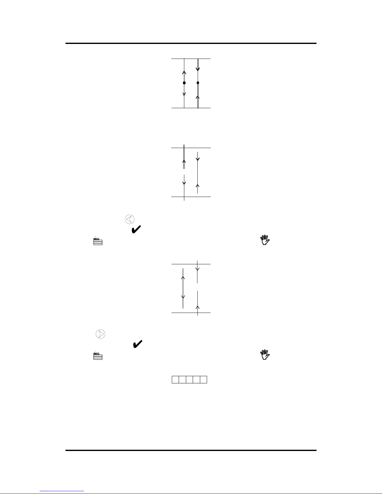
User’s Manual SummaPaint PC1500
Operation 2-81
The test pattern is similar to the LAT-test.
Check the quality of the cuts: the end of the vertical cuts should coincide precisely with
the horiz ontal cuts, without any gaps .
Weed out the rectangle and if you obtained a pattern as illustrated above, decrease the valu e displayed on
the LCD by pressing the
jogging key to correct closing of the lines cut.
To repeat the test, press the key.
Press the key to repeat the calibration procedure or press the key to interrupt
the routine.
However, if you obtained a pattern as illustrated above, increase the value displayed on the LCD by
pressing the
jogging key to correct closing of the lines cut.
To repeat the test, press the key.
Press the key to repeat the calibration procedure or press the key to interrupt
the routine.
A complementary test has been added to fine tune the LONG. adjustment.
Press the 1 key to perform the horizontal test; all the squares should be identical.
1.48. CUT BORDER
The CUT BORDER sub-menu is used to cut the border of the media area which was defined during the
load sequence. This function is particularly useful if you want to verify the exact cutting area.
Page 82

User’s Manual SummaPaint PC1500
Operation 2-82
1.49. MENU PLOT
The MENU PLOT is a hard copy of the present machines configuration, i.e. the items selected in the
USER CONFIG sub-menus described in Section 2.3. The plot is organised by menu categories to show
the current values for the various USER CONFIG 1(->4) configurations. To run this plot, load a sheet of
plotting paper and install a pen.
Page 83

User’s Manual SummaPaint PC1500
Operation 2-83
NOTE
It is strongly recommended to produce a MENU PLOT hard copy each time
you alter the cutter configuration. The resulting plot should be kept with the
machine’s documentation in order to provide other users with details of the
actual configurations of the unit.
1.50. CONFIDENCE cuT
The CONFIDENCE cut performs an electrical and mechanical test of the cutter to make sure that the
cutter is fully operational. A media sheet of at least A3/A- size should be used for this plot.
1.51. DIN CUT
The DIN CUT also performs an electrical and mechanical test of the cutter, in order to check the cut
quality, but also provides the user with feedback on knife setting, knife pressure, knife offset and cutting
depth.
This cut is always run as a DIN A4 portrait/A-size image, regardless of the actual size of the media
loaded. If the media loaded is smaller than DIN A4/A-size, part of the outer box will be clipped (not cut).
This cut is always executed in the sequence prescribed by the ISO DIN standard.
1.52. CALIbration OPOS.
The CALIBRATION OPOS sub-menu is used to calibrate the OPOS (Optical positioning system).
This calibration is normally done in the factory. When the system is no longer working precisely a
calibration test must be performed. Calibration allows to fix the exa ct distance betwe en the knife tip and
the sensor.
⇒ To calibrate the optical system, proceed as follows:
1. Power up the unit and load a piece of black vinyl with a white backing. The load procedure is
described in section 1.
2. Set the origin on a clean, blank part of the vinyl. Defining the origin is described in section 1.
3. Press the key (MENU) key until the message ‘INTERNAL TEST’ is displayed on the LCD.
Page 84

User’s Manual SummaPaint PC1500
Operation 2-84
↓ INTERNAL TESTS
4. Press the jogging key until the message ‘ CAL OPOS’ is displayed.
È INTERNAL TESTS
Ç CAL. OPOS
Press the key to confirm the selection.
The cutter will now cut out a rectangle.
5. The message ‘WEED RECTANGLE’ will appear on the display:
WEED RECTANGLE
PRESS MENU
Weed carefully with tweezers the rectangle cut and press the key.
The cutter will now measure the rectangle and set its calibration parameters.
1.53. Optical sensor
The OPTICAL SENSOR option is a useful routine to check whether or not OPOS sensor is functioning
properly. If the sensor is placed on black the sensor output should be High (above 1500). If the sensor is
placed on white the sensor output should be low (below 700).
1.54. SYSTEM TESTS
The SYSTEM TESTS sub-menu covers the menu items you only occasionally need to adjust .
Press the ENTER key to access the different sub-menu items which are explained in section 2.6 below.
Page 85
User’s Manual SummaPaint PC1500
Operation 2-85
1.55. SYSTEM TESTS
The SYSTEM TESTS menu is a special set of procedures which are not required for normal cutter
operation. Field service personnel, however, will use the SYSTEM TESTS menu occasionally. When in
SYSTEM TESTS, the cutter is fully operational and performs as described in this manual.
1.56. LANGUAGE
The MENU LANGUAGE sub-menu is used to set or modify the dialogue language on the LCD. Press the
or jogging key until the desired language is displayed on the LCD and press to confirm.
The information on the LCD can be displayed in English, French, German, Dutch, Spanish or Italian.
1.57. ROM REVISION
Selecting the ROM REVISION option, by pressing the key will furnish the details on the cutter’s
ROM revision. This information is often helpful to technicians when diagnosing problems over the
telephone.
1.58. SERVICE PLOT
The SERVICE PLOT provides information about the cutter, which is helpful when requesting service for
your cutter. The SERVICE PLOT is always plotted at the same size and should be performed with a pen
on paper.
The plot shows the cutter model number, the revision numbers of the installed ROM (Read Only
Memory) circuits, the selected baud rate, the resolution an d bu ffer (memory) size.
CAUTION
The following test routines are normally restricted to CalComp’s Field Service
Personnel.
1.59. SENSOR SETUP
The SENSOR SETUP option is a useful routine to check whether or not the front and rear media sensor
are functioning properly and whether the switching levels of these sensors are correctly set.
1.60. CAM SENsOR
The OPTICAL SENSOR option is a useful routine to check whether or not the cam sensor is functioning
properly. The cam sensor is the sensor mounted to the cut carriage. This sensor senses the location of the
pinch rollers.
1.61. CALIBRATION
Page 86

User’s Manual SummaPaint PC1500
Operation 2-86
CALIBRATION allows to adjust the length of the lines cut, within the specifications.
For instance, if a cut line should measure 100 mm exactly, the cutter can be adjusted for any discrepancy.
1.62. ROLL TEST
The ROLL TEST option is a useful routine to check whether the pick-up roll and the pick-up sensor are
functioning properly or not. The pick-up roll can be activated by means of the arrow keys
1.63. RS232 TEST
The RS232 TEST routine verifies the unit’s RS-232-C serial communications (transmit data, receive data,
and hardware handshaking) circuits. This test does not require pen, knife or media to be loaded.
1.64. RAM TEST
This test completely checks the RAM bit by bit.
When running this test the unit will not respond. After this test, power the unit off, then on again.
1.65. INSTALL MENU
The INSTALL MENU routine restores the factory-defined menu settings in all four USER CONFIG
menus. This test routine can be performed without a tool and without media.
1.66. COIL SETUP
This test is used to calibrate knife and pen pressure and to set the knife and pen “landing”.
After adjustment, the value is saved in the system’s non-volatile RAM.
To execute this test a tension gauge of ± 100 gr and ± 500 gr is required.
In the upper line of the display the desired pressure appears and in the bottom line of the display th e va lue
that has to be sent to the head to reach this pressure (this value is between 0 and 127).
1.67. LCD CONTRAST
The LCD CONTRAST submenu is used to adjust the contrast (or intensity) of the liquid crystal display
on the control panel.
Press the or jogging key to increase or reduce the contrast and press to confirm.
Page 87
User’s Manual SummaPaint PC1500
Operation 2-87
1.68. printer settings
Î To access any printer setting, proceed as follows:
1. Power the machine on.
2. Load printing media.
3. Install the ink cartridges and a knife or a pen .
4. Press the key until PRINTER SETTINGS is displayed and press the jogging key.
5. Press the or jogging key until the desired printer setting is displayed.
6. To perform the test (if availab le) press the 1 key.
7. To change parameters (if available), press the key.
To exit from this menu and go to another menu, press the key until the desired menu is displayed.
To exit from the menus and put the machine on line again, press the key.
Figure 2-6 shows the different PRINTER SETTINGS sub -menus.
NOTE
The printer settings are not related to the user configurations. (For all four user configurations the
same values are used.)
Note
All the tests described further in this section can also be activated through the
SummaPaint Control program. To install this program read the readme.txt file on the
installation disk.
Page 88
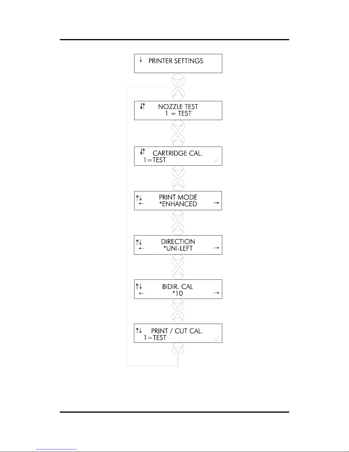
User’s Manual SummaPaint PC1500
Operation 2-88
FIGURE 2 - 6
PRINTER SETTI NGS
Page 89
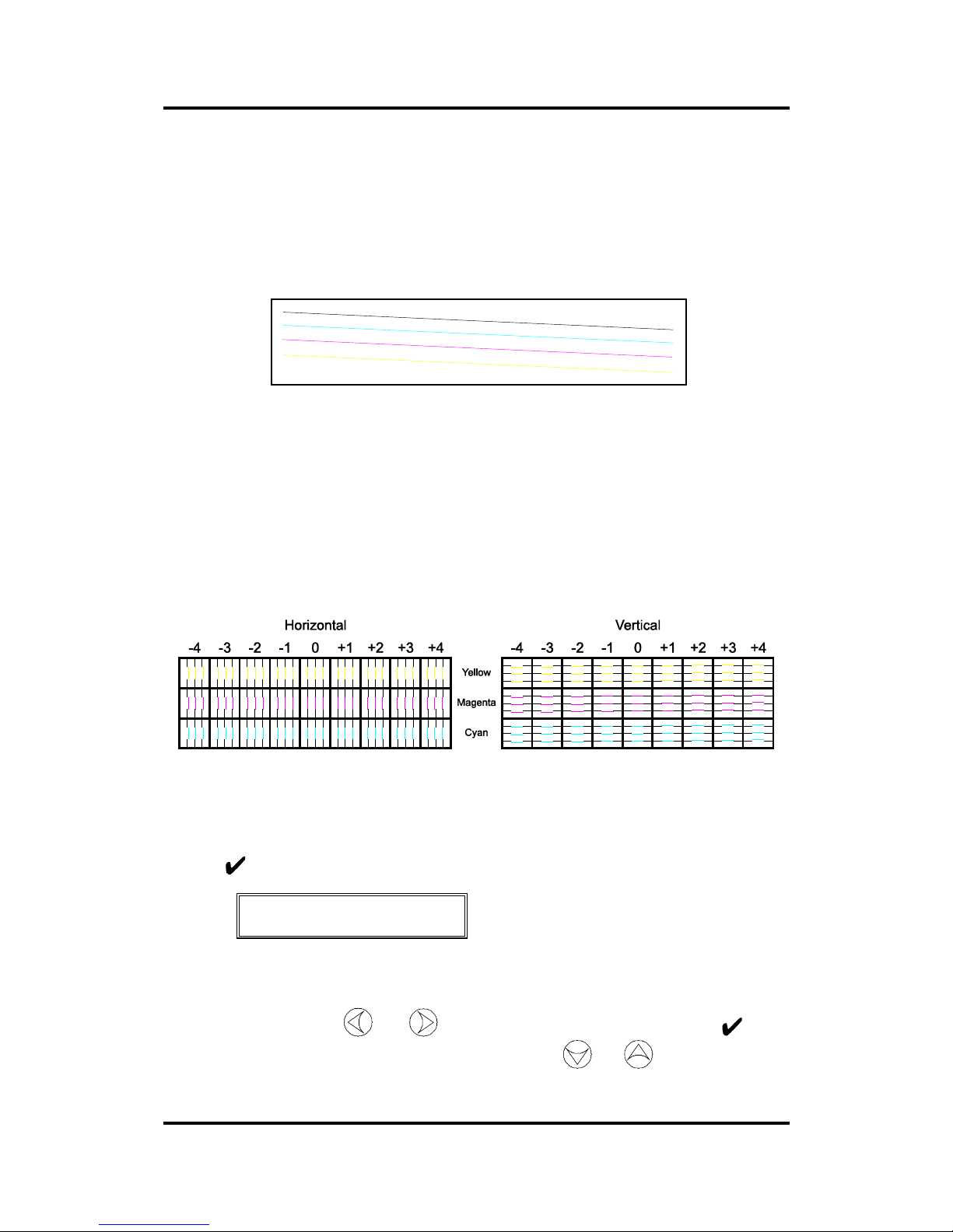
User’s Manual SummaPaint PC1500
Operation 2-89
1.69. NOZZLE TEST
To make sure that all nozzles of the 4 cartridges are working properly, do the NOZZLE TEST.
Press the 1 key to perform a nozzle test as illustrated in the figure below.
NOZZLE TEST PATTERN
When all nozzles are working fine, the four slanting lines will be continuous. If one color line is
interrupted, one ore more nozzles will be blocked. Repeat this test a second time. If some nozzles are still
blocked, the cartridge needs to be cleaned (see section 3).
1.70. cartridge cal.
The CARTRIDES CAL(ibration) aligns the cartridges.
Press the 1 Key to perform a color calibration test as illustrated below:
After printing the color calibration test you can change the values for the horizontal and vertical offset of
the printed color with reference to the black.
Select again ‘COLOR CAL.’
Press the key to change the color calibration parameters.
↑↓ CYAN HORZ.
← *0 →
Examine the horizontal and vertical tests carefully. Verify per row in which square the colored lines are in
a direct line with the black lines. The value figuring on top of the corresponding column is the value that
has to be entered. Press the
and jogging keys to change the value. Press the key to
confirm the selection (an * appears in front of the value). Press the
and jogging keys to switch
between the different parameters. After changing the values a final test can be done by pressing the
1
Key.
Page 90

User’s Manual SummaPaint PC1500
Operation 2-90
1.71. print mode
The PRINT MODE sub-menu is used to set print mode.
The PRINT MODE default value is ENHANCED.
PRINT MODE can be set to ENHANCED or DRAFT.
The draft mode is fast but can only be used for line drawings or technical drawings. For printing pictures
the enhanced mode should always be used.
1.72. direction
The DIRECTION sub-menu determines during which print-carriage movement the machine actually
prints.
The default setting is UNI-LEFT.
DIRECTION can be set to UNI-LEFT, UNI-RIGHT and BI-DIRECTIONAL.
UNI-LEFT : Printing takes place while the carriage moves to the left.
UNI-RIGH : Printing takes place while the carriage moves to the right.
BI-DIRECTIONAL: Printing takes place while the carriage moves to the left and also when it moves to
the right. The BI-DIRECTIONAL mode is fast but requires an additional calibration (see 2.1.73).
1.73. Bi-dir CAL
The BI-DIR(ectional) CAL(ibration) aligns the left and right printing movements to each other in order to
print bi-directional.
In line drawings the result of the bi-directional calibration can easily be seen.
Examine whether the lines are smooth. If the lines are not in a direct line then the bi-directional value has
to be changed.
The values can be changed by pressing the and jogg ing keys. Pr ess the key to confirm the
selection (an * appears in front of the value).
Page 91
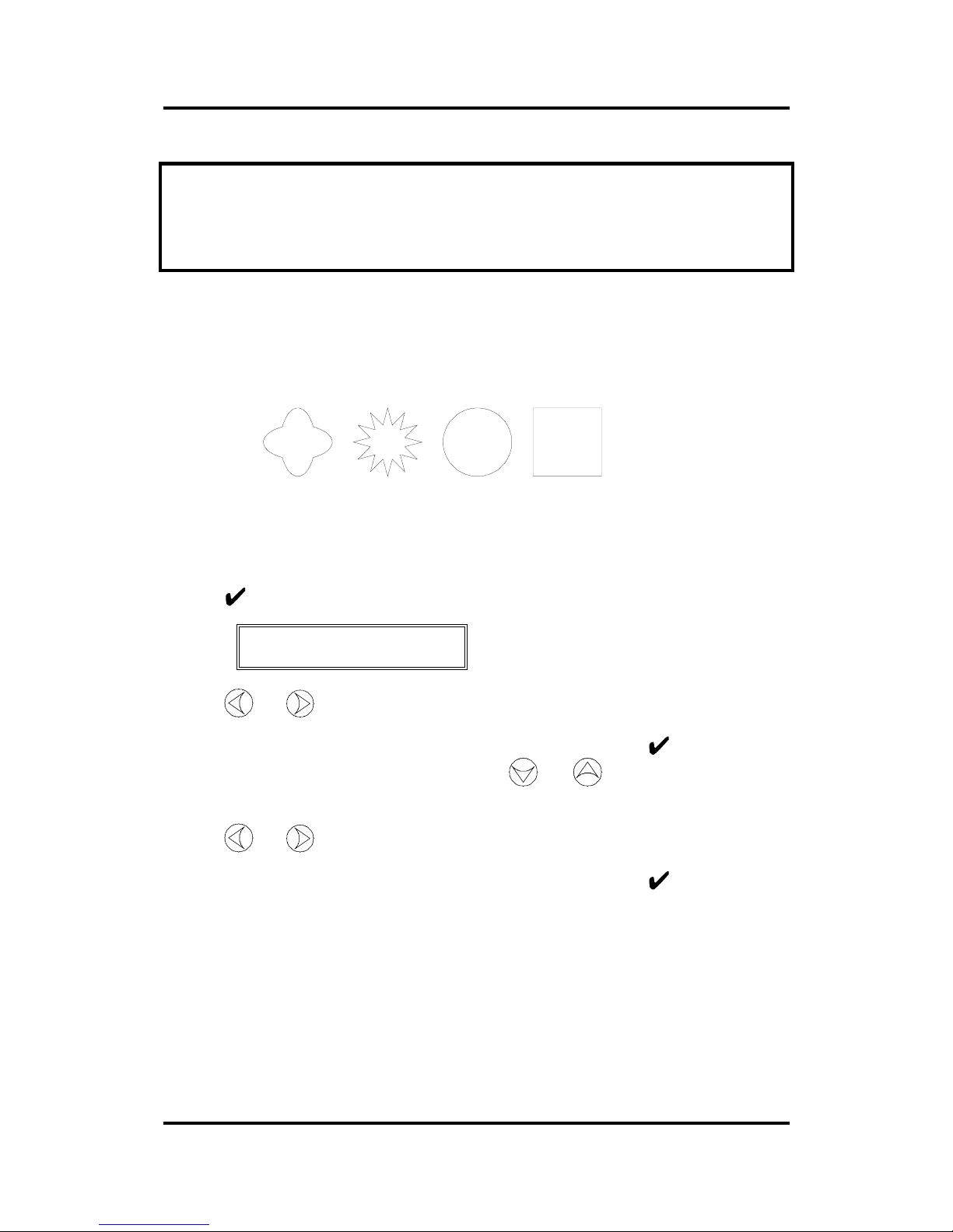
User’s Manual SummaPaint PC1500
Operation 2-91
NOTE
When using the SummaPaint Control program, a special test can be activated to do the bidirectional calibrating test.
1.74. print / cut cal.
The PRINT / CUT CAL. calibrates the position of the four cartridges in relation to the cutting head.
Press the 1 Key to perform a Print and Cut calibration test as illustrated below:
Result :
After printing the Print and Cut calibration test you can change the values for horizontal and vertical
offset.
Select again ‘PRINT / CUT CAL.’
Press the key to change the vertical offset.
↑↓ VERT. OFFSET
← *0 →
Press the and jogging keys to change the value. The value must correspond with the number
of dots the printed part has to move so that printed and cut lines are ex actly the same. Moving upwards
increases the parameter, moving downwards decreases the parameter. Press the
key to confirm the
selection (an * appears in front of the value). Press the
and jogging keys to switch to the
horizontal offset.
Press the and jogging keys to change the value. The value must correspond with the number
of dots the printed part has to move so that printed and cut lines are exactly the same. Moving to the left
increases the parameter, moving to the right decreases the parameter. Press the
key to confirm the
selection (an * appears in front of the value).
After changing the values a final test can be done by pressing the 1 Key.
Page 92

User’s Manual SummaPaint PC1500
Operation 2-92
SECTION 3
GENERAL INFORMATION
1.75. MAINTENANCE & cleaning
The SummaPaint PC1500 has a number of sliding surfaces made of smooth metals and plastics. They are
virtually friction-free and require no lubrication. They will, however, collect dust, which may affect the
performance of the machine. Keep the SummaPaint PC1500 as clean as possible by using a dust cover.
When necessary, clean the unit with a soft cloth dampened with isopropyl alcohol or mild detergent. Do
not use abrasives.
1.76. Cleaning the service station.
NOTE
When the machine is used intensively it is obliged to clean the service station daily.
The service station contains ink reservoirs. The head will spit in these reservoirs periodically to preven t
the nozzles from blocking. If the service station is not cleaned regularly, the ink will overflow and cause
difficulties.
Î To clean the service station, proceed as follows:
1. Power on the unit. Make sure th at the media is properly loaded.
2. When the unit is ‘Online’ pr ess the key. The print carriage will move beside the service station.
Every three seconds a beep will warn you that the print carriage is not in the service station.
Page 93
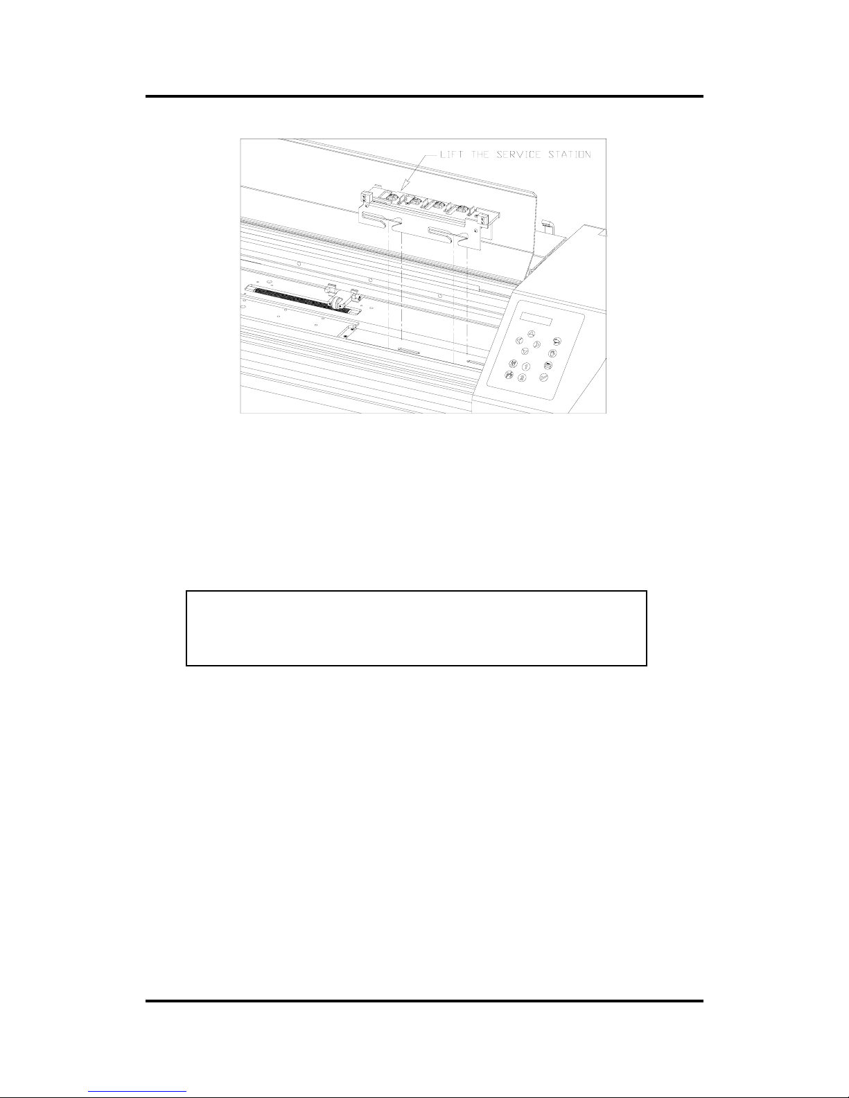
User’s Manual SummaPaint PC1500
Operation 2-93
FIGURE 3 - 1
CLEANING THE SERVICE STATION
3. Lift the service station and move it a little so that it comes free from the machine body.
4. First hold the complete service station in a tank of water. This will allow most of the ink to flow away.
Then clean the service station more carefully with a soft dampened cloth.
CAUTION
Consult your local Authority for regulations regarding the waste of
used water.
5. Dry the service station as well as you can to prevent corrosion.
6. Place the service station back in place.
7. Move the service station as far as possible to the left.
8. Press on any key so that the print carriage moves back.
Page 94
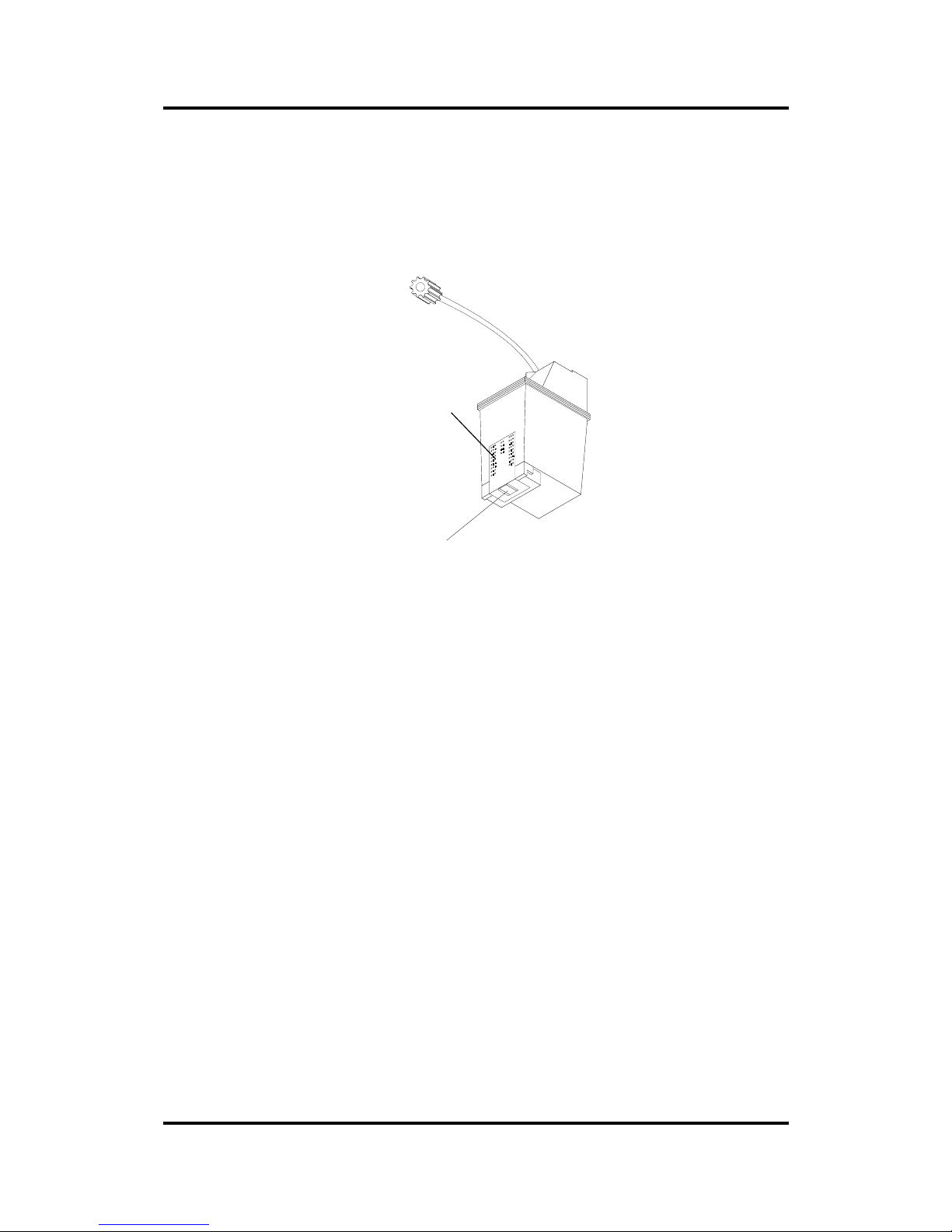
User’s Manual SummaPaint PC1500
Operation 2-94
1.77. cleaning cartridges
When a cartridge has blocked nozzles, try the following suggestions to make them work again. Repeat the
first suggestion a few times before trying the other suggestions.
Copper
Contacs
Print nozzles
FIGURE 3 - 2
CLEANING INK CARTRIDGE
• Clean the nozzles with a soft dampened cloth. Pressing the sides of the cartridge will force ink to
come out of the nozzles. Do this while holding the print nozzles downwards.
• Clean the copper contacts of the cartridge with a soft cloth.
• Clean the copper contacts of the print carriage with a soft cloth.
• To find out whether a cartridge is not working properly anymore due to blocked nozzles or bad
contacts, switch two cartridges from place and repeat the prime test.
• If the cartridge is still not working fine, force some ink to come by pumping air in the ink bo ttles with
the prime bulb while printing. However, do not do this when printing final pictures. The cartridge
could start leaking for a while.
• If the cartridge is still not working fine, place it on top of a wet (destiled water)cloth during a few
minutes so that the water has time to dissolve the blocked nozzles.
• Use evacuation tool that came with the accessories (see section 3.1.4).
• If the cartridge is still not working fine, immerse the nozzles in an ultrasonic bath for about 15
seconds.
• Hold the print head above steaming water for about 30 seconds.
1.78. Cleaning the tubes
Page 95

User’s Manual SummaPaint PC1500
Operation 2-95
NOTE
It is advised to clean the tubes :
• when a set of tubes has not been used for a couple of days.
• weekly or monthly, depending on the type of ink. When using pigmented ink a weekly flush will
prevent clogging.
Î To clean the tubes, proceed as follows:
1. Remove the cart ri dges as described in section 1.
2. Connect the prime bulb to the connector on the print carriage, and open
the clips nearby the ink bottles.
3. Blow all the ink back into the bottle.
4. Close the clips and disconnect the ink bottles. Place the ink bottle and the
bottle support away from the machine. Disconnect the prime bulb.
5. Fill the syringe with destilled water. Use cleaning tool to catch water.
6. Connect the syringe to the print carriage and flush the tubes with the
water. Repeat steps 5 and 6 several times if necessary.
7. If the tubes will not be used in the first few days, close the tubes on both
sides and proceed with step 8 at the moment you are going to use the
tubes again. Otherwise proceed with step 8 now.
8. Connect the prime bulb to the print carriage and remove all the water by
pumping air through it.
9. Refill the tubes with ink (See Section 1).
1.79. EVACUATION TOOL
Page 96
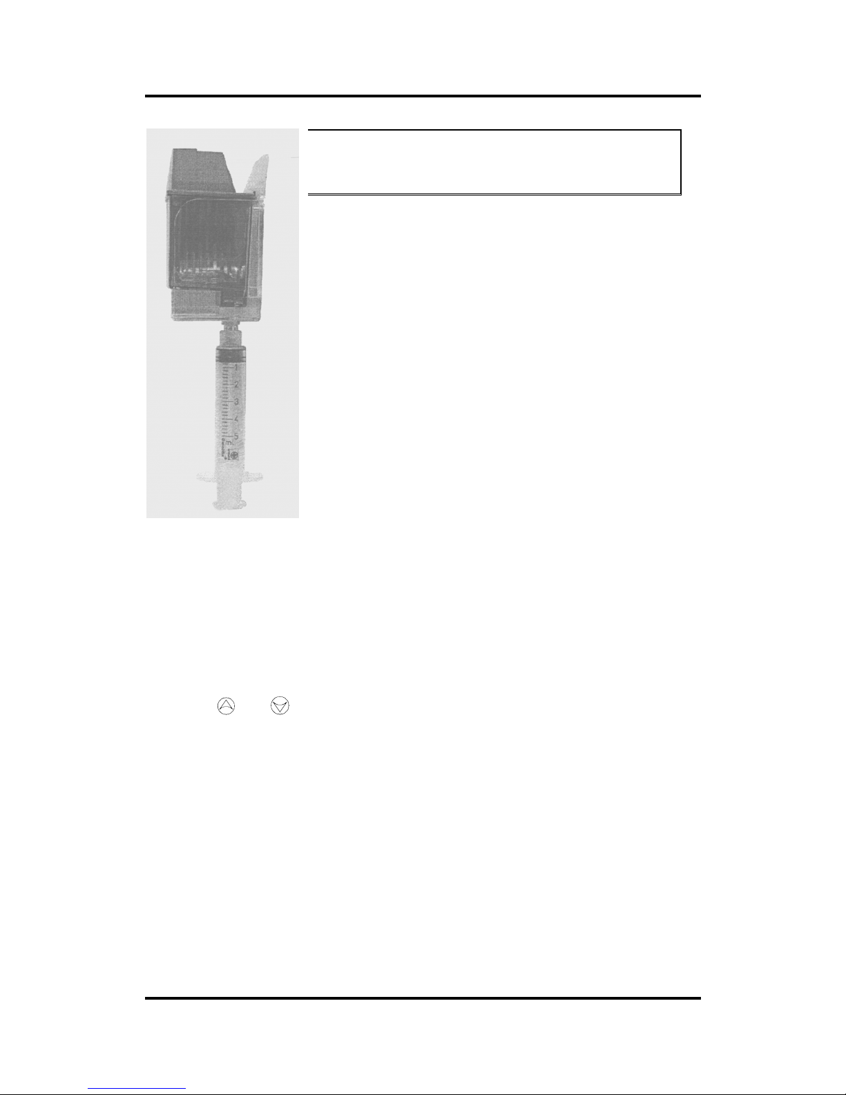
User’s Manual SummaPaint PC1500
Operation 2-96
CAUTION
BEFORE USING THIS TOOL MAKE SURE TO WEAR
PROTECTIVE CLOTHING IN ORDER NOT TO GET INK
STAINS ON YOUR CLOTHING.
If the cartridges are blocked or if the micro chamber is less then half full,
then use this special tool.
Simply put the cartridge in the holder and pull gently on the syringe until
ink comes in the syringe. If the micro chamber is less then half full, then
very gently push the ink back into the micro chamber. DO NOT PUT TO
MUCH PRESSURE ON THE SYRINGE. DO NOT TRY TO PUT
ALL THE INK BACK INTO THE MICRO CHAMBER THIS WILL
BREAK THE SEAL AND DESTROY THE EVACUATION TOOL.
Wait until the pressure in the cartridge and micro chamber are stable.
Then remove the cartridge from the holder and put it back on the machine.
Excess ink in the syringe can be returned in the bottles on the tray.
Clean the tools carefully after each in order not to mix ink colors.
1.80. CLEANING THE drive sleeves
After a time, the sleeves of the drive drum may become clogged with
accumulated residue from the media. This situation may affect the traction
as the media will tend to slip between the pinch rollers and the drive
sleeves.
Î To clean the drive sleeves, proceed as follows:
1. First disable the sensors by covering them, or via the configuration menu (see 2.4.12
Media Sensor).
2. Place the cutter in local operation. (See Section 2.2.2.) Local operation will allow you
to use the control panel jogging keys, even when no media is loaded.
3. Remove the backing from a piece of vinyl. Place the vinyl with the tacky side down
between one of the pinch rollers and a drive sleeve. Lower the pi nch roller arm.
4. Use the and jogging keys to move the piece of vinyl backward and forward
several times, until a ll residue is removed from the drive sleeves.
5. Raise the pinch roller arm and remove the piece of vinyl.
6. Repeat steps 3 through 5 for the other drive sleeves.
7. Set the machine’s power switch to OFF.
Page 97
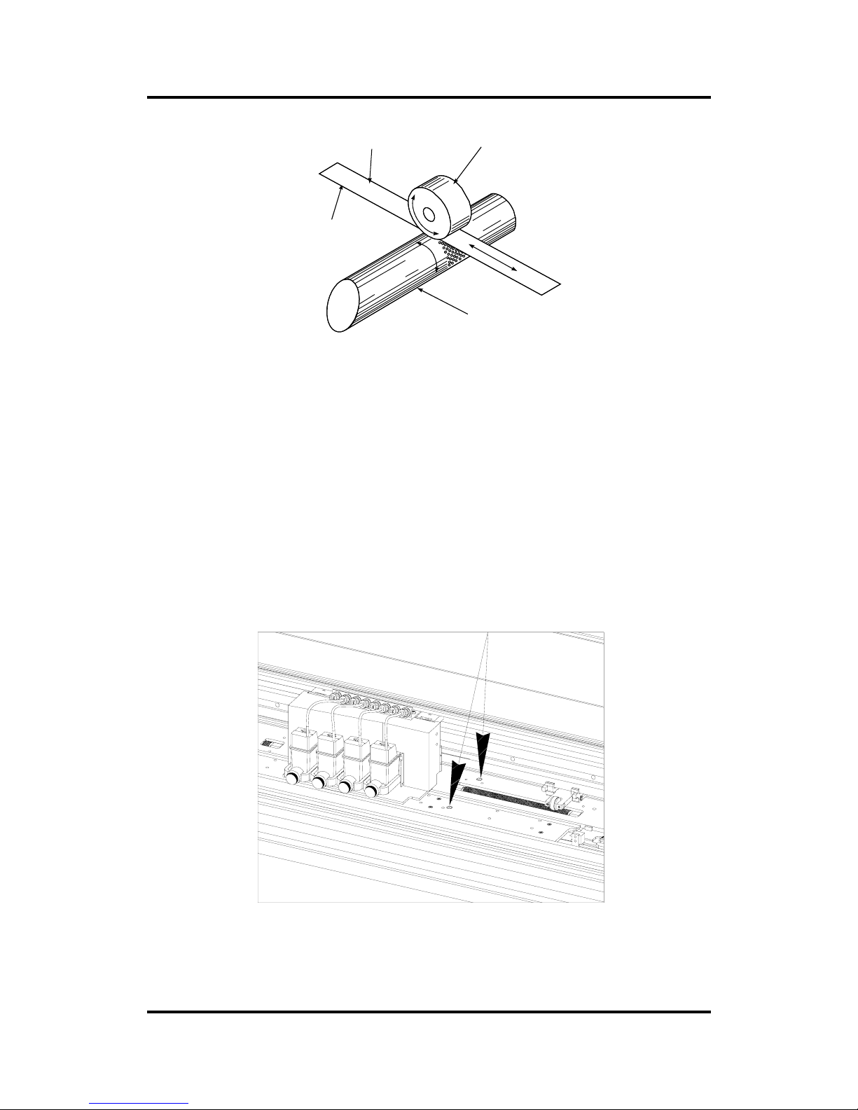
User’s Manual SummaPaint PC1500
Operation 2-97
SLEEVE
VINYL STRIP PINCH ROLLER
TACKY SIDE ON BOTTOM
FIGURE 3 - 3
CLEANING OF THE DRIVE SLEEVES
1.81. cleaning the sensors.
After a certain time, the sensor may become dirty with accumulated residue from the media. This
situation may cause malfunctioning of the unit.
Î To clean the sensor area, proceed as follows:
1. The sensors are located on the machine’s right side. One sensor is located on the front platen, the
other sensor is located on the rear platen.
FIGURE 3 - 4
LOCATION OF THE SENSORS
2. To keep the sensors clean, it is sufficient to wipe them out now and then with a cotton swab.
Page 98
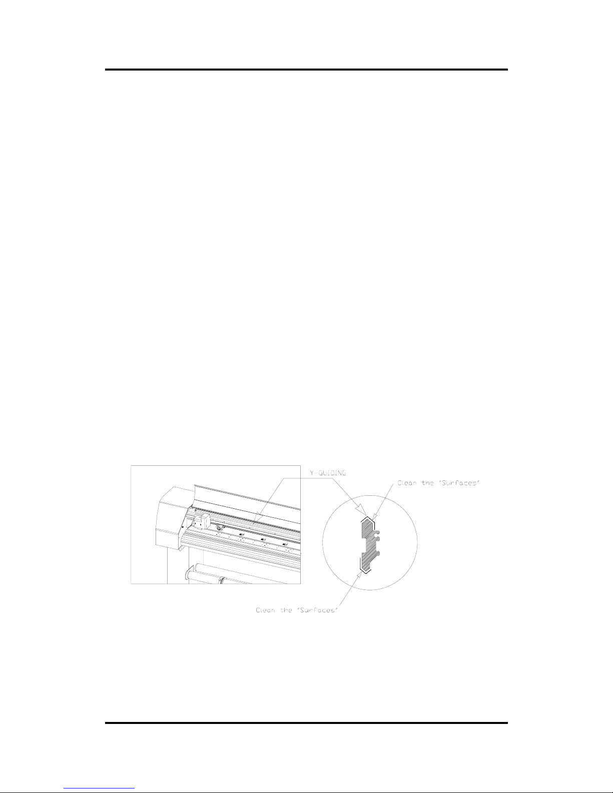
User’s Manual SummaPaint PC1500
Operation 2-98
1.82. Cleaning the nose piece.
The nose piece may become dirty with accumulated residue from the vinyl, which will result in poor cut
quality.
Î To clean the nose piece, proceed as follows:
1. Gently take out the knife or ball-point pen by turning the knife holder anticlockwise.
2. Observe the orientation of the nose piece first and then push it out of its holder.
3. Remove any remaining vinyl residue using a brush or a pair of tweezers.
4. Place the nose piece back.
5. Install the knife or ball-point pen holder as described in section 1.10.
1.83.
1.84. Cleaning the Y-guiding.
After a certain time, the y-guiding may become dirty with dust and accumulated residue from the carriage
wheels. This may lead to bad printing and bad cutting quality.
Î To clean the y-guiding, proceed as follows:
1. Set the machine’s power switch to OFF, and open the safety cover.
2. The Y-guiding is the guiding on which the two carriages (print en cut carriages) are moving.
FIGURE 3 - 5
CLEANING THE Y-GUIDING
3. Clean the surfaces that are under a 45 degree angle with a soft cloth (both on top and underneath).
4. Move the carriages manually so that you can clean the complete guiding.
Page 99
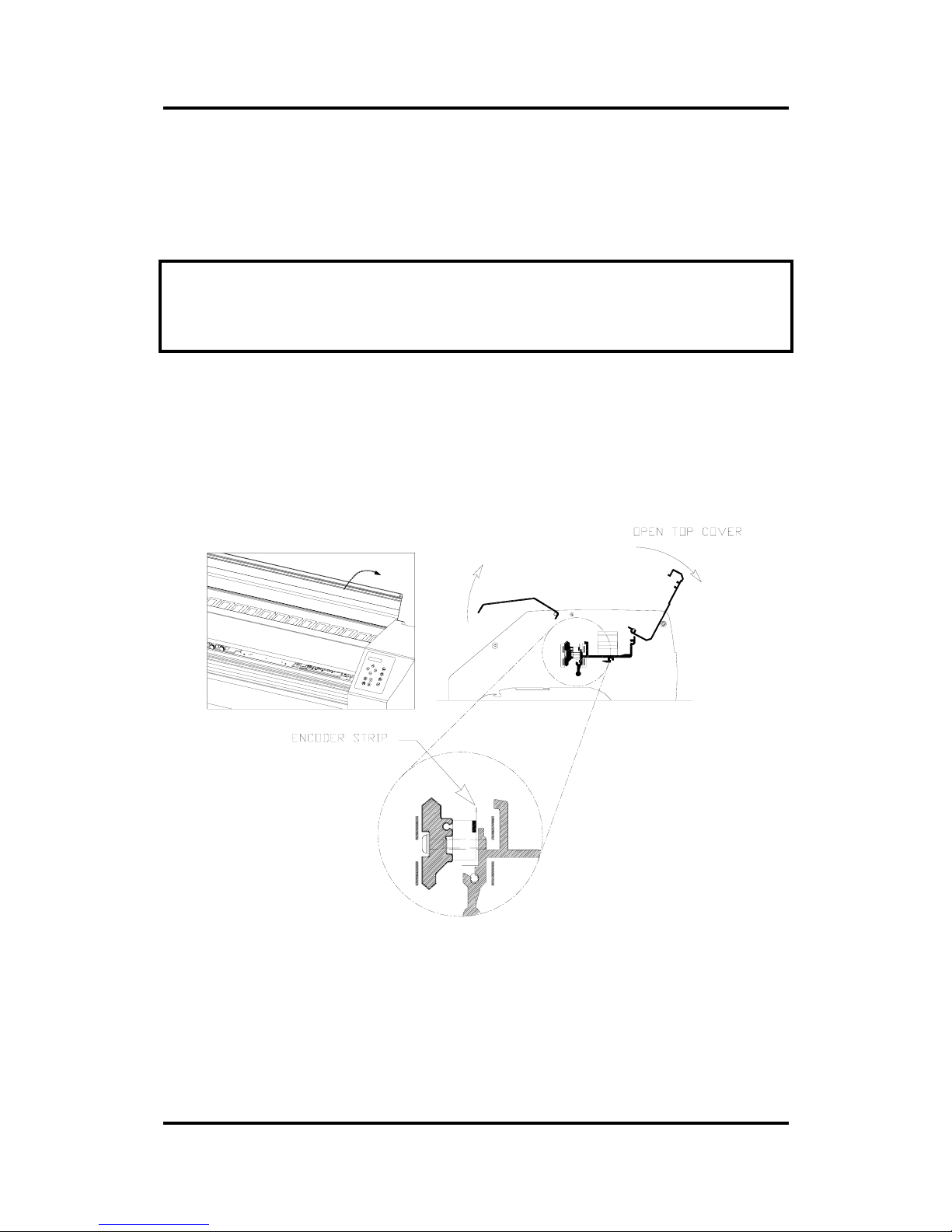
User’s Manual SummaPaint PC1500
Operation 2-99
1.85. Cleaning the Encoder strip
After a certain time, the encoder strip may become dirty, which may cause the drawing to shift while
printing.
CAUTION
The encoder strip is an essential and very fragile part. Handle it with extreme care.
Î To clean the encoder strip, proceed as follows:
1. Set the machine’s power switch to OFF.
2. Open the safety-cover partly with one hand, and reach with the other hand under the safety cover to
open the top cover.
FIGURE 3 - 6
CLEANING THE ENCODER STRIP
3. The encoder strip is situated about 2,5 cm (1”) behind the Y-guiding (see 3.1.83).
4. Clean both sides of the strip extremely carefully with a soft cloth.
Move the carriages manually so that you can clean the complete strip.
Page 100
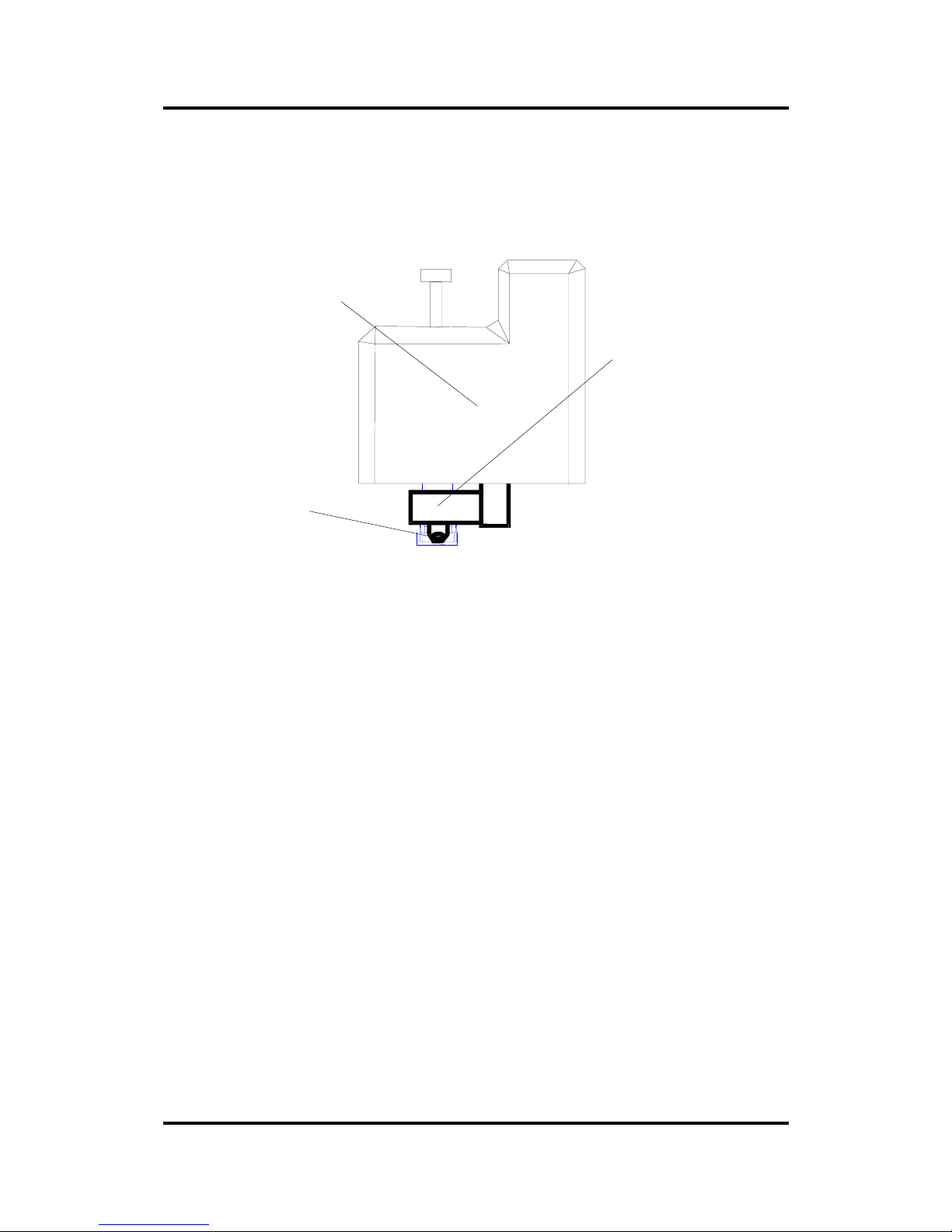
User’s Manual SummaPaint PC1500
Operation 2-100
1.86. CLEANING the OPOS SYSTEM.
The optical system will collect dust. It is therefore advised to clean the sensor regularly with a co tton b ud.
The sensor has a small hole so that it can be cleaned easily.
Hole
Cutting
Head
OPOS
SYSTEM
FIGURE 3 - 7
CLEANING THE OPOS SYSTEM
 Loading...