

Page 1

User’s Manual
Rev 011
Page 2

FCC Notice
The S CLASS™ cutters have been tested and found to comply with the limits for Class A
digital devices, pursuant to Part 15 of the FCC Rules. These limits are designed to provide
reasonable protection against harmful interference when the equipment is operated in a
commercial environment. The cutters generate, use and can emit radio frequency energy
and, if not installed and used in accordance with the instruction manual, may cause harmful
interference to radio communications.
Operation of the cutters in a residential area is likely to cause harmful interference, in which
case the user will be required to correct the interference at his own expense.
Caution!
Changes or modifications not expressly approved by Summa, which is responsible for FCC
compliance, could void the user’s authority to operate this equipment.
DOC Notice
The S CLASS™ cutters do not exceed the Class A limits for radio noise for digital apparatus
set out in the Radio Interference Regulations of the Canadian Department of
Communications.
Notice
Summa reserves the right to modify the information contained in this User Manual at any
time without prior notice. Unauthorized copying, modification, distribution or display is
prohibited. All rights reserved.
Waste Electrical and Electronic Equipment (WEEE) Directive
Directive 2002/96/EC of the European Parliament and of the Council
The symbol (right) is shown on this product. It indicates that the product
should not be disposed of with regular household waste, but should be
disposed of separately.
Electrical and electronic equipment can contain materials that are
hazardous to the environment and human health and therefore should
be disposed of at a designated waste facility or returned to your retailer
for the appropriate recycling to take place.
If you wish to dispose of this product and the product still functions, please consider
recycling/reusing it by donating it to a charity shop, selling it or part-exchanging it with
your retailer.
Copyright © 2011 Summa
Page 3

Registering Your Cutter
Please register your cutter on the following link:
http://www.summa.be/registration.html
Failure to register may result in delayed responses to your warranty and service inquiries.
Contact Information
All inquiries, comments or suggestions concerning this and other Summa manuals should
be directed to:
North America and Asia
Pacific
Eastern United States and
Latin America
Europe, Africa and
Middle East
Summa, Inc
10001 Lake City Way NE
Seattle, WA 98125
USA
Main Office
+1-206-527-1050
+1-800-527-7778
Fax
+1-206-527-1046
Support
Sales
Web Site
www.summausa.com
Summa East, Inc
222 Jubilee Drive
Peabody, MA 01960
USA
Main Office
+1-978-531-1991
+1-888-527-1050
Fax
+1-978-531-1993
Support
Sales
Web Site
www.summausa.com
Summa, bvba
Rochesterlaan 6
B-8470 GISTEL
Belgium
Main Office
+32 (0)59 270011
Fax
+32 (0)59 270063
Support
Sales
Web Site
www.summa.be
Page 4

Welcome
Congratulations on your purchase of the new S CLASS™ cutter!
The S CLASS™ cutters are made for sign-makers who demand the very best in cut quality.
Four versatile modes let you switch between Cutting, Cutting in FlexCut, Plotting or
Pouncing. So even if your workspace is limited, your output options aren't.
Unrivalled tracking delivers guaranteed accuracy on cuts up to 12 meters (40 feet) long. So
you won't have to monitor your cuts, even when you're sending the long jobs through.
The S CLASS™ T cutters with genuine tangential operation, and not simply "tangential
emulation," handle a wider range of materials and cut with unparalleled precision.
In short, the S CLASS™ cutters take cutting signs to a new level.
This manual is a reference guide for installing and operating the S CLASS™ cutter models.
Page 5

Table of contents I
Table of Contents
1 Setup ............................................................................................................... 1-1
1.1 Unpacking the Cutter .......................................................................................... 1-1
1.1.1 Removing the packaging from the cutter...................................................................... 1-1
1.1.2 Setting up the stand .............................................................................................................. 1-2
1.1.3 Mounting the cutter on the stand .................................................................................... 1-4
1.2 S CLASS™ Cutter Components ............................................................................ 1-5
1.2.1 The Cutter as viewed from the front ................................................................................ 1-5
1.2.2 The Cutter as viewed from the back ................................................................................ 1-7
1.3 Connecting the Cutter to the Mains ................................................................... 1-9
1.3.1 Grounding (“Earthing”) ......................................................................................................... 1-9
1.3.2 Operating voltage ................................................................................................................... 1-9
1.3.3 Powering-on the cutter ..................................................................................................... 1-10
1.4 Connecting the Cutter to a Computer ............................................................. 1-11
1.4.1 USB connection .................................................................................................................... 1-11
1.4.1.1 Connecting the S CLASS™ cutter to a PC using a USB cable ....................... 1-11
1.4.1.2 Connecting the S CLASS™ cutter to a Mac using a USB cable .................... 1-12
1.4.2 RS-232 Connection .............................................................................................................. 1-13
1.4.3 Wireless Connection (optional)....................................................................................... 1-14
1.4.3.1 Setting up the S CLASS™ cutter in a WLAN (Wi-Fi
®
compatible) ................. 1-14
1.4.3.2 Connecting the S CLASS™ cutter ad hoc. ........................................................... 1-19
1.4.3.3 Webserver ..................................................................................................................... 1-25
1.5 Loading Media ................................................................................................... 1-26
1.5.1 Pinch roller positioning ..................................................................................................... 1-26
1.5.2 Pinch roller pressure setting ............................................................................................ 1-27
1.5.2.1 Changing pressure on older models ................................................................... 1-27
1.5.2.2 Changing pressure on the new models ............................................................. 1-28
1.5.3 Loading media ...................................................................................................................... 1-29
1.5.4 Media load procedure ........................................................................................................ 1-32
1.6 Tool Installation ................................................................................................ 1-36
1.6.1 Cutters with drag head ...................................................................................................... 1-36
1.6.1.1 Knife installation ......................................................................................................... 1-36
1.6.1.2 Pen installation ............................................................................................................ 1-40
1.6.1.3 Pouncing pin installation ......................................................................................... 1-40
1.6.2 Cutters with tangential head ........................................................................................... 1-41
1.6.2.1 Tangential knife installation ................................................................................... 1-41
1.6.2.2 Pen installation ............................................................................................................ 1-45
1.6.2.3 Pouncing pin installation ......................................................................................... 1-45
1.6.2.4 Drag knife installation ............................................................................................... 1-46
1.6.3 Replacement of the separation knife blade ............................................................... 1-46
Page 6

S CLASS™ cutter User’s Manual
Table of contents II
2 Basic Operation .............................................................................................. 2-1
2.1 Touch Screen ....................................................................................................... 2-1
2.1.1 Touch screen ............................................................................................................................ 2-2
2.1.2 Configuration ........................................................................................................................... 2-3
2.1.3 Online/Pause ............................................................................................................................ 2-4
2.1.4 Actions ........................................................................................................................................ 2-4
2.2 How to Set Tool Parameters ............................................................................... 2-5
2.2.1 Setting tool type ...................................................................................................................... 2-5
2.2.2 Changing tool pressure ........................................................................................................ 2-6
2.2.3 Changing drag knife offset .................................................................................................. 2-6
2.2.4 Calibrating a tangential knife ............................................................................................. 2-7
2.3 How to Set Cutting Speed ................................................................................. 2-11
2.4 How to Change the User (Quick Parameter Change) ...................................... 2-13
2.5 How to Make Sure the Sign Has the Correct Size ............................................ 2-14
2.6 Touch screen shortcuts ..................................................................................... 2-16
2.6.1 Changing origin .................................................................................................................... 2-16
2.6.2 Changing velocity ................................................................................................................ 2-16
2.6.3 Changing tool pressure ..................................................................................................... 2-17
2.6.4 Changing user ....................................................................................................................... 2-17
2.7 How to track difficult media ............................................................................. 2-18
3 OPOS (Optical POSitioning) .......................................................................... 3-1
3.1 Introduction......................................................................................................... 3-1
3.2 Basic OPOS operation ......................................................................................... 3-1
3.2.1 OPOS calibration ..................................................................................................................... 3-2
3.2.2 Media calibration .................................................................................................................... 3-3
3.3 Detailed OPOS Operation ................................................................................... 3-5
3.3.1 Creating the graphic with the markers ........................................................................... 3-5
3.3.2 OPOS XY ..................................................................................................................................... 3-8
3.3.3 Printing the graphic ............................................................................................................... 3-9
3.3.4 Loading the graphic into the cutter .............................................................................. 3-10
3.3.5 Setting the parameters for the OPOS sensor ............................................................. 3-10
3.3.6 Registering the markers ..................................................................................................... 3-11
3.3.7 Cutting the contour ............................................................................................................ 3-12
3.4 Automating Tasks with OPOS .......................................................................... 3-13
3.4.1 Cutting multiple copies of a graphic on the same roll ........................................... 3-13
3.4.2 Cutting the same graphic on multiple media sheets.............................................. 3-14
3.4.3 OPOS Barcode ....................................................................................................................... 3-16
3.5 Cutting through ................................................................................................ 3-17
Page 7

S CLASS™ cutter User’s Manual
Table of contents III
4 Detailed Operation ........................................................................................ 4-1
4.1 Introduction......................................................................................................... 4-1
4.2 Action Menu ........................................................................................................ 4-1
4.3 Configuration Menu ............................................................................................ 4-2
4.3.1 Settings ....................................................................................................................................... 4-3
4.3.1.1 Tool ..................................................................................................................................... 4-3
4.3.1.2 Advanced cutting .......................................................................................................... 4-3
Overcut: ...................................................................................................................................... 4-3
OptiCut: ...................................................................................................................................... 4-3
FlexCut: ....................................................................................................................................... 4-4
Panels: ......................................................................................................................................... 4-5
Sort Vectors: .............................................................................................................................. 4-5
Smoothing: ................................................................................................................................ 4-6
Concatenation: ......................................................................................................................... 4-6
4.3.1.3 General .............................................................................................................................. 4-6
Media sensor: ............................................................................................................................ 4-6
Language: .................................................................................................................................. 4-7
Panel Units: ................................................................................................................................ 4-7
Recut Offset: .............................................................................................................................. 4-7
Cut off margin: ......................................................................................................................... 4-7
Roll up media: ........................................................................................................................... 4-8
Autoload: .................................................................................................................................... 4-8
Front Margin: ............................................................................................................................ 4-8
4.3.1.4 OPOS .................................................................................................................................. 4-9
4.3.1.5 Communication .......................................................................................................... 4-10
Wireless: ................................................................................................................................... 4-10
Baudrate (RS232): ................................................................................................................. 4-11
Parity (RS232): ........................................................................................................................ 4-11
RTS/DTR (RS232): .................................................................................................................. 4-11
Emulation language: ........................................................................................................... 4-12
HP-GL origin: .......................................................................................................................... 4-12
DM-PL addressing: ............................................................................................................... 4-12
USB class: ................................................................................................................................. 4-13
4.3.1.6 Speed in detail ............................................................................................................. 4-13
Velocity long vectors: ......................................................................................................... 4-13
TurboCut: ................................................................................................................................ 4-14
FlexCut velocity: ................................................................................................................... 4-14
4.3.2 Tests and setup ..................................................................................................................... 4-15
4.3.2.1 OPOS settings .............................................................................................................. 4-15
4.3.2.2 Length calibration ...................................................................................................... 4-15
4.3.2.3 Coil setup ....................................................................................................................... 4-15
4.3.2.4 Calibrate knife .............................................................................................................. 4-16
4.3.2.5 Factory defaults ........................................................................................................... 4-16
4.3.2.6 Confidence test ........................................................................................................... 4-16
4.3.2.7 Media sensor setup .................................................................................................... 4-16
4.3.2.8 DIN A4 Test .................................................................................................................... 4-17
4.3.2.9 RS232 test ...................................................................................................................... 4-17
4.3.2.10 Calibrate touch screen .............................................................................................. 4-17
4.3.2.11 ROM REVISION ............................................................................................................. 4-17
4.3.2.12 Copy current user ....................................................................................................... 4-17
4.3.3 User ........................................................................................................................................... 4-18
Page 8

S CLASS™ cutter User’s Manual
Table of contents IV
5 Maintenance and Cleaning ........................................................................... 5-1
5.1 Introduction......................................................................................................... 5-1
5.1.1 Cleaning the drive system ................................................................................................... 5-1
5.1.2 Cleaning the media sensors ................................................................................................ 5-2
5.1.3 Cleaning the Y-Guide Rail .................................................................................................... 5-3
5.1.4 Cleaning the nose piece (tangential machine only) ................................................... 5-3
5.1.5 Cleaning the OPOS system .................................................................................................. 5-4
5.1.6 Changing the fuse .................................................................................................................. 5-5
6 Specs and General Information .................................................................... 6-1
6.1 Introduction......................................................................................................... 6-1
6.1.1 Product features ...................................................................................................................... 6-1
6.2 Specifications ...................................................................................................... 6-3
6.2.1 Cutter ........................................................................................................................................... 6-3
6.2.2 Media ........................................................................................................................................... 6-3
6.2.3 Knife, pen and pouncing tool ............................................................................................. 6-4
6.2.4 Interface ..................................................................................................................................... 6-5
6.2.5 Firmware .................................................................................................................................... 6-5
6.2.6 Performance ............................................................................................................................. 6-6
6.2.7 Certifications ............................................................................................................................. 6-6
6.2.8 Environmental .......................................................................................................................... 6-7
6.2.9 Electrical ..................................................................................................................................... 6-7
Page 9

S CLASS™ cutter User’s Manual
Table of contents V
List of Figures
1-1 S CLASS™ cutter fully boxed .................................................................................................................. 1-1
1-2 Contents OF box stand ............................................................................................................................ 1-2
1-3 Mounting horizontal panel .................................................................................................................... 1-2
1-4 Mounting feet and casters ..................................................................................................................... 1-2
1-5 Mounting basket tubes ........................................................................................................................... 1-3
1-6 Preparing to install the linen basket ................................................................................................... 1-3
1-7 Orientation of the holes in the c-shaped tubes .............................................................................. 1-3
1-8 Stand for the S CLASS™ cutter completely assembled ................................................................ 1-4
1-9 Position of the screws .............................................................................................................................. 1-4
1-10 S CLASS™ cutter, front view ................................................................................................................. 1-5
1-11 S CLASS™ cutter, rear view ................................................................................................................... 1-7
1-12 Properly grounded connection ......................................................................................................... 1-9
1-13 Cutter is loaded and ready ............................................................................................................... 1-10
1-14 Cutter is ready no media loaded .................................................................................................... 1-10
1-15 configuration utility for access point ............................................................................................ 1-14
1-16 POsition pinch rollers ......................................................................................................................... 1-26
1-17 Standard pressure ................................................................................................................................ 1-27
1-18 Reduced pressure ................................................................................................................................ 1-27
1-19 reducing pressure ................................................................................................................................ 1-28
1-20 Pinch roller lever ................................................................................................................................... 1-29
1-21 Media flanges ........................................................................................................................................ 1-29
1-22 Position media flange on cutter ..................................................................................................... 1-29
1-23 Feeding roll media without using media flanges .................................................................... 1-30
1-24 Media position ...................................................................................................................................... 1-30
1-25 Pinch roller lever ................................................................................................................................... 1-31
1-26 Removing the drag knife holder from the clamp ..................................................................... 1-36
1-27 Removing the knife from the standard drag knife holder .................................................... 1-36
1-29 Dual clamp drag head ........................................................................................................................ 1-37
1-30 Knife pressure test pattern ............................................................................................................... 1-38
1-31 Removing the tangential knife holder ......................................................................................... 1-41
1-32 Removing knife from the tangential knife holder .................................................................... 1-41
1-34 Inserting the tangential knife holder ............................................................................................ 1-42
1-35 Knife depth adjustment ..................................................................................................................... 1-42
1-36 Knife pressure test pattern ............................................................................................................... 1-43
1-37 Razor blade for automatic SEPARATION OF MEDIA ................................................................ 1-46
2-1 Touch screen ............................................................................................................................................... 2-1
2-2 Screen saver ................................................................................................................................................ 2-1
2-3 Online status screen ................................................................................................................................. 2-4
2-4 Correct knife offset pattern .................................................................................................................... 2-7
2-5 Possible knife calibrations ...................................................................................................................... 2-8
2-7 Length calibration pattern .................................................................................................................. 2-14
2-8 Shortcut areas in start-up screen ...................................................................................................... 2-16
Page 10

S CLASS™ cutter User’s Manual
Table of contents VI
3-1 Position media fro multiple sheet .................................................................................................... 3-15
3-2 Opos barcode job loaded .................................................................................................................... 3-16
3-3 FlexCut principle ..................................................................................................................................... 3-17
3-4 Combined contour cut and cutting through ............................................................................... 3-20
4-1 Action Menu ................................................................................................................................................ 4-1
4-2 Configuration Menu ................................................................................................................................. 4-2
4-3 Overcut .......................................................................................................................................................... 4-3
4-4 Sensor setup ............................................................................................................................................. 4-16
5-1 Lifting the pinch roller ............................................................................................................................. 5-2
5-2 Placement of vinyl strip ........................................................................................................................... 5-2
5-3 Media sensors S CLASS™ cutters .......................................................................................................... 5-2
5-4 Sliding surfaces on Y-guide rail ............................................................................................................ 5-3
5-5 Cleaning OPOS sensor ............................................................................................................................. 5-4
5-6 Power entry module ................................................................................................................................. 5-5
Page 11

S CLASS™ cutter User’s Manual
Table of contents VII
List of Tables
1-1 Default RS-232 settings of the S CLASS™ cutter ............................................................. 1-13
6-1 S CLASS™ Cutter specifications ................................................................................................... 6-3
6-2 S CLASS™ media specifications ................................................................................................... 6-3
6-3 S CLASS™ tools .................................................................................................................................... 6-4
6-4 S CLASS™ interface specifications ............................................................................................. 6-5
6-5 S CLASS™ firmware ............................................................................................................................ 6-5
6-6 S CLASS™ performances ................................................................................................................. 6-6
6-7 S CLASS™ environmental specifications .................................................................................. 6-7
6-8 S CLASS™ accessories .................................................................................................................. 6-10
Page 12
Setup 1-1
1 Setup
1.1 Unpacking the Cutter
NOTE: Save the shipping box and any other packaging items in case the cutter needs to be
shipped. Do not ship the cutter without first completely repacking it in its original
packaging.
Before unpacking the cutter, make sure that there is enough space to assemble the stand
and to set the cutter aside to insert the stand screws.
CAUTION: For safety reasons, no fewer than two people should be involved in unpacking
the cutter.
1.1.1 Removing the packaging from the cutter
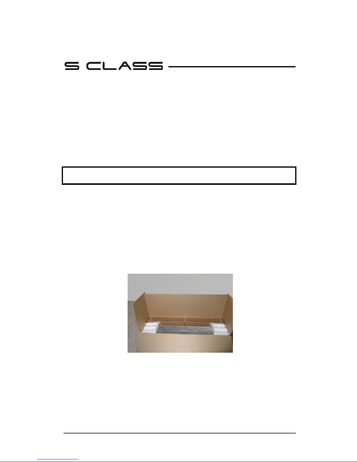
1. Remove the straps and the staples and open the lid of the box.
2. The cutter is packed in foil and sits in front of the box. Behind the cutter is the box
containing the stand. The accessories are located at the bottom in a separate box.
Check first whether everything is present.
3. Do not throw away the packaging. Shipping it without the original box voids any
warranty.
FIG 1-1
1-1 S CLASS™ CUTTER FULLY BOXED
Page 13
S CLASS™ cutter User’s Manual
Setup 1-2
1.1.2 Setting up the stand
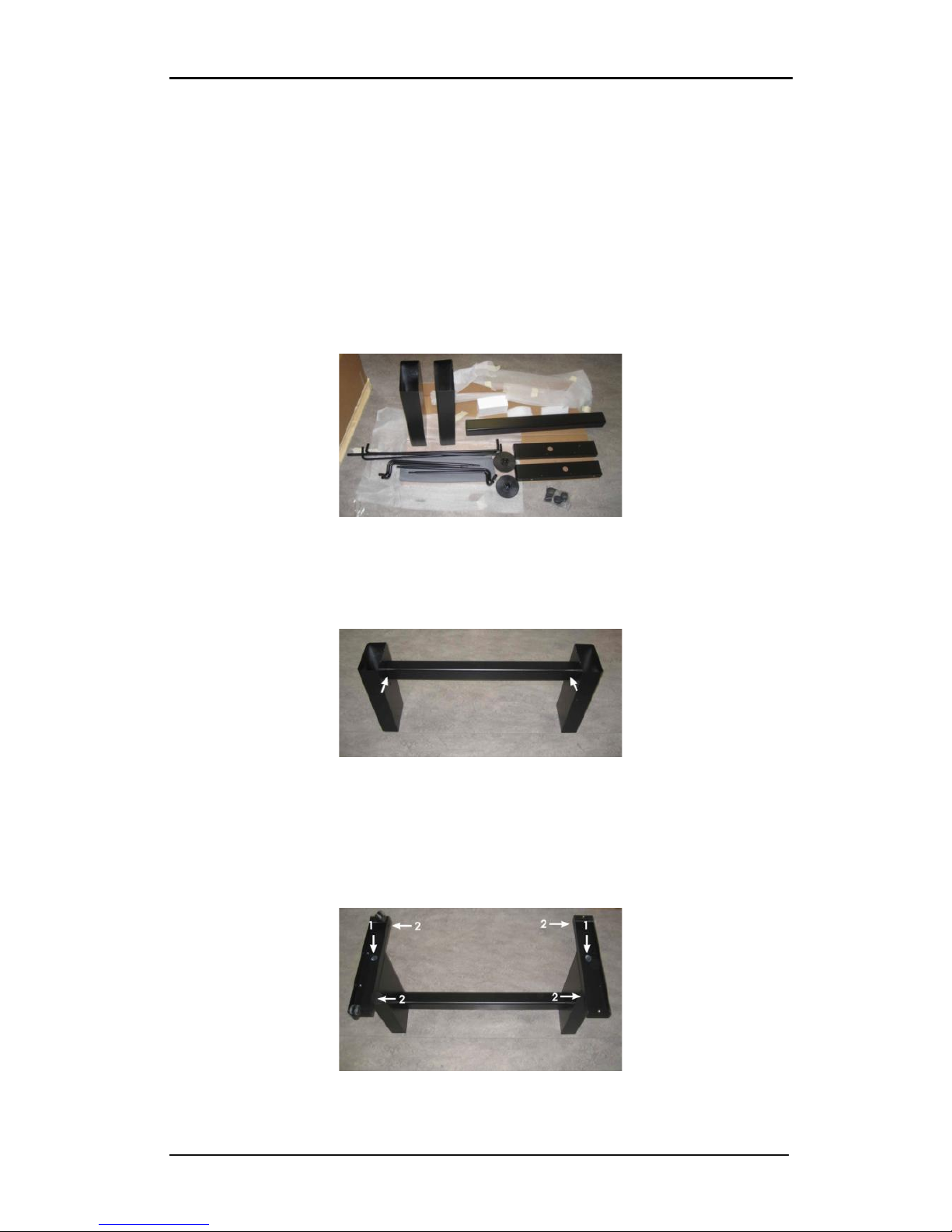
1. Verify that the stand is complete. The box containing the stand should contain
following:
a. 2 legs, left and right
b. 2 feet, left and right
c. Horizontal panel
d. Media flanges
e. Total of 7 tubes for [media] basket
f. Linen media basket
g. Bag of 4 casters, screws and other accessories to mount the stand
FIG 1-2
1-2 CONTENTS OF BOX STAND
2. Mount the horizontal panel between the two legs of the stand with 4 screws at each
side.
FIG 1-3
1-3 MOUNTING HORIZONTAL PANEL
3. Turn the stand upside down and mount the 2 feet at each side with 4 screws. Take care
to position the feet so that all the holes in the feet corresponds to the holes in the legs
(left and right) as in the picture (1), and the 4 holes in the feet all point towards the
middle (2). Screw in the 4 casters.
FIG 1-4
1-4 MOUNTING FEET AND CASTERS
Page 14
S CLASS™ cutter User’s Manual
Setup 1-3
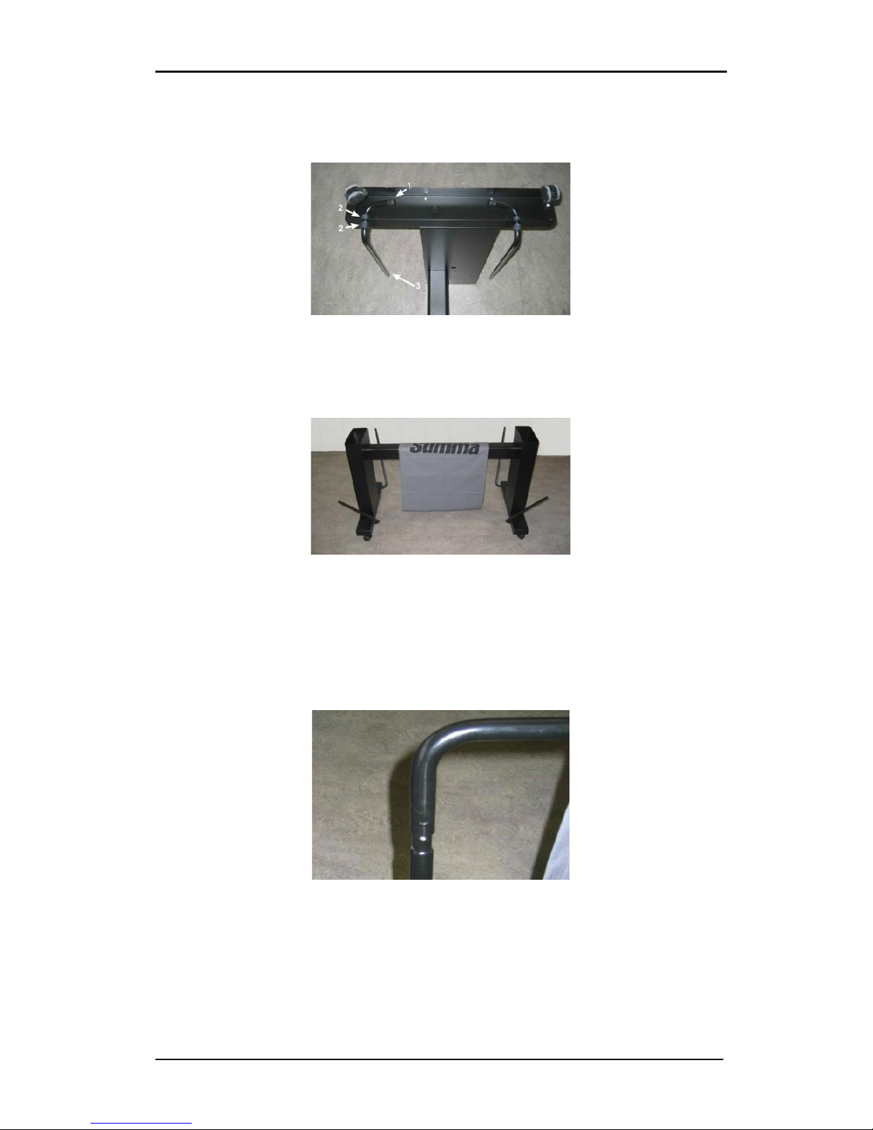
4. Attach on the left and right the 4 tubes for the basket as shown in figure 1-5 below. On
each tube, put the end cap (1) and the two saddle clips (2) to fix the tube in its place.
Position the shorter tube (3) at the rear side (side of the horizontal panel).
FIG 1-5
1-5 MOUNTING BASKET TUBES
5. Turn the stand upright and put the media basket on the horizontal panel as shown in
figure 1-6 below.
FIG 1-6
1-6 PREPARING TO INSTALL THE LINEN BASKET
6. Take one of the large c-shaped tubes and put it through the front hem in the linen
basket. Make sure the holes are oriented right-side up so that the tubes click securely in
place. Then put the tube on the two front tubes that stick out of the feet. Slide the tubes
together, while pressing down on the spring loaded ball stopper, until the ball locks
into place.
FIG 1-7
1-7 ORIENTATION OF THE HOLES IN THE C-SHAPED TUBES
7. Click a saddle clip onto one side of the tube. Insert the other end of the tube through
the middle hem of the linen basket and then into the hole in the leg of the stand. Then
guide the other end of the tube into the hole on the leg and secure with a saddle clip.
Page 15
S CLASS™ cutter User’s Manual
Setup 1-4
8. Make sure the linen basket is guided under the horizontal panel. Take the last large c-
shaped tube and feed it through the rear hem in the linen basket. Then put the tube on
the two rear tubes that stick out of the feet. Make sure the holes are oriented right-side
up so that the tube clicks securely on the tubes. The finished stand should look like the
stand in the picture below (Figure 1-8).
FIG 1-8
1-8 STAND FOR THE S CLASS™ CUTTER COMPLETELY ASSEMBLED
9. The right leg has a hole in the foot and a cutout in the leg to guide the power cable and
data cable. If you plan to use these cable guides, then put the cables in place before
mounting the cutter on the stand.
1.1.3 Mounting the cutter on the stand
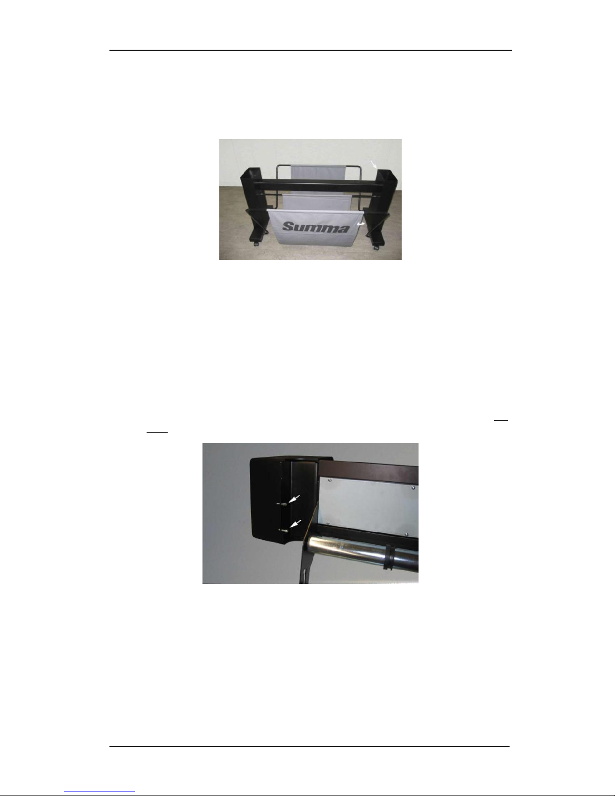
1. Carefully take the cutter out of the box and lay it on its back (first spread out the
cardboard of the stand box, and then rest the cutter on that cardboard). Then insert left
and right two screws and turn them 3 turns in. Do not put a screw in at the front.
FIG 1-9
1-9 POSITION OF THE SCREWS
2. Put the cutter on its stand. Put in the two extra screws in . Then secure all six screws.
3. Loosen the cutting head. Raise the pinch rollers to remove the protection strip from
underneath the pinch roller assemblies.
Page 16
S CLASS™ cutter User’s Manual
Setup 1-5
1.2 S CLASS™ Cutter Components
1.2.1 The Cutter as viewed from the front
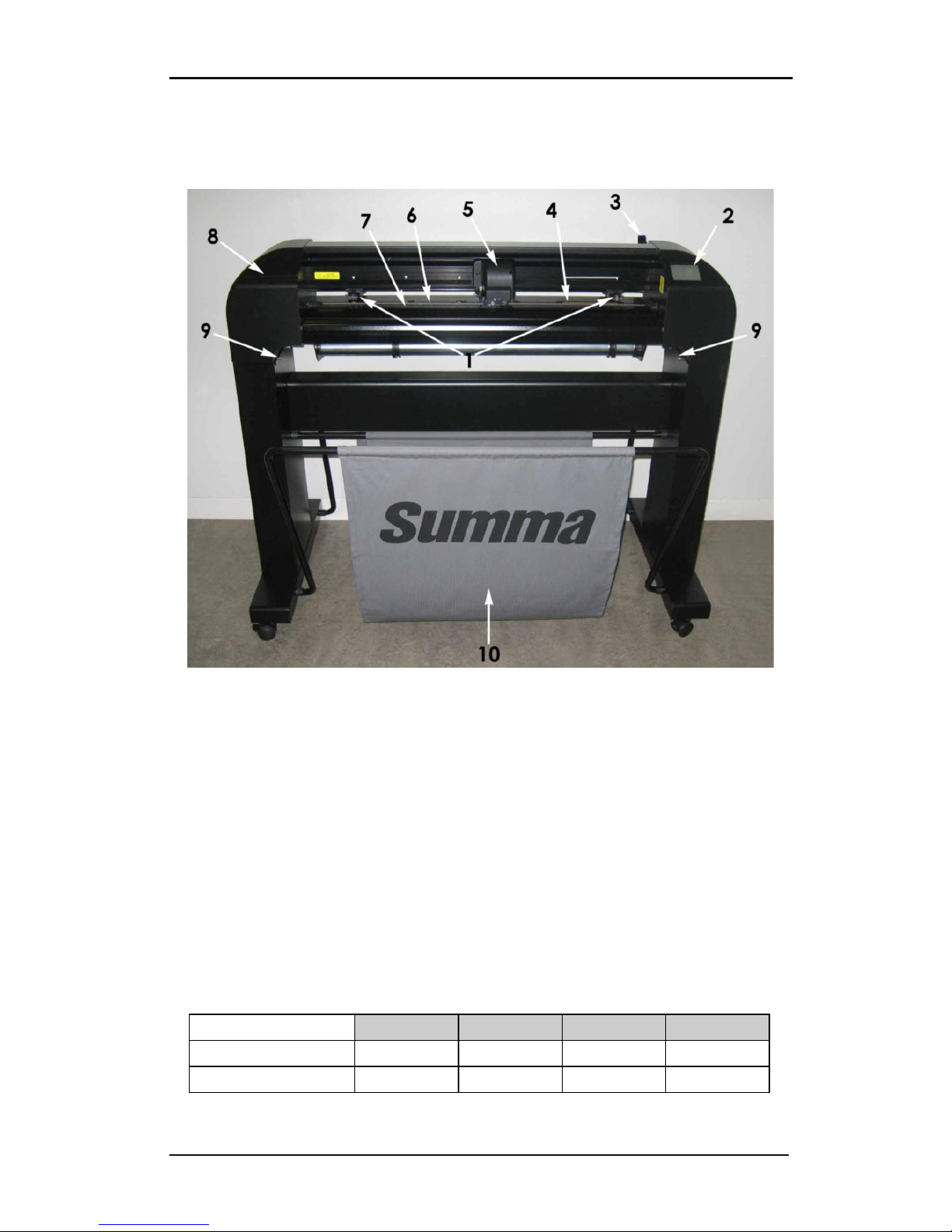
FIG 1-10
1-10 S CLASS™ CUTTER, FRONT VIEW
1. Pinch rollers: The pinch rollers clamp the media to the drive system to ensure accurate
tracking. The S120(T) has one and the S160(T) and S 140(T) have two extra pinch rollers
to ensure that wide media stays flat in the middle. The outer drive pinch rollers have a
selectable pressure; the extra rollers in the middle can be enabled or disabled.
2. Touch panel: All cutter activity can be initiated from the 320x240 dot touch panel. The
panel displays information about the cutter’s current status and/or actions that need to
be taken.
3. Pinch roller lever: This lever is used to raise and lower the pinch rollers for media
loading.
4. Media drive sleeves: The media drive sleeves move the media only when the pinch
rollers are in the “down” position. The following table lists the number of sleeves
installed on each model of the S CLASS™ cutters.
Number of sleeves
S75 (T) S120 (T) S140 (T) S160 (T)
Short sleeve 4 7 8 9
Long sleeve 1 1 1 1
Page 17

S CLASS™ cutter User’s Manual
Setup 1-6
5. Tool carriage: The tool carriage is the mount for the knife holder, pen or pouncing tool.
It has also holds the Optical POSitioning sensor (OPOS) and a cut-off knife to cut a sheet
from the roll when a job is finished.
6. Cutting strip: A self-healing orange strip helps avoid any damage to the knife tip when
no media has been loaded. Since cutting is done on the cutting strip, it is essential that
the strip remains intact.
7. Pouncing strip: An extra black strip to pounce on.
8. Tool holder: The left end cap has a rim so it can be used for tool storage.
9. Screws to secure the cutter base: Make sure all three screws are secured at each side
before the cutter is used.
10. Media basket: The stand and linen media basket come standard with all S CLASS™
cutters.
Page 18
S CLASS™ cutter User’s Manual
Setup 1-7
1.2.2 The Cutter as viewed from the back
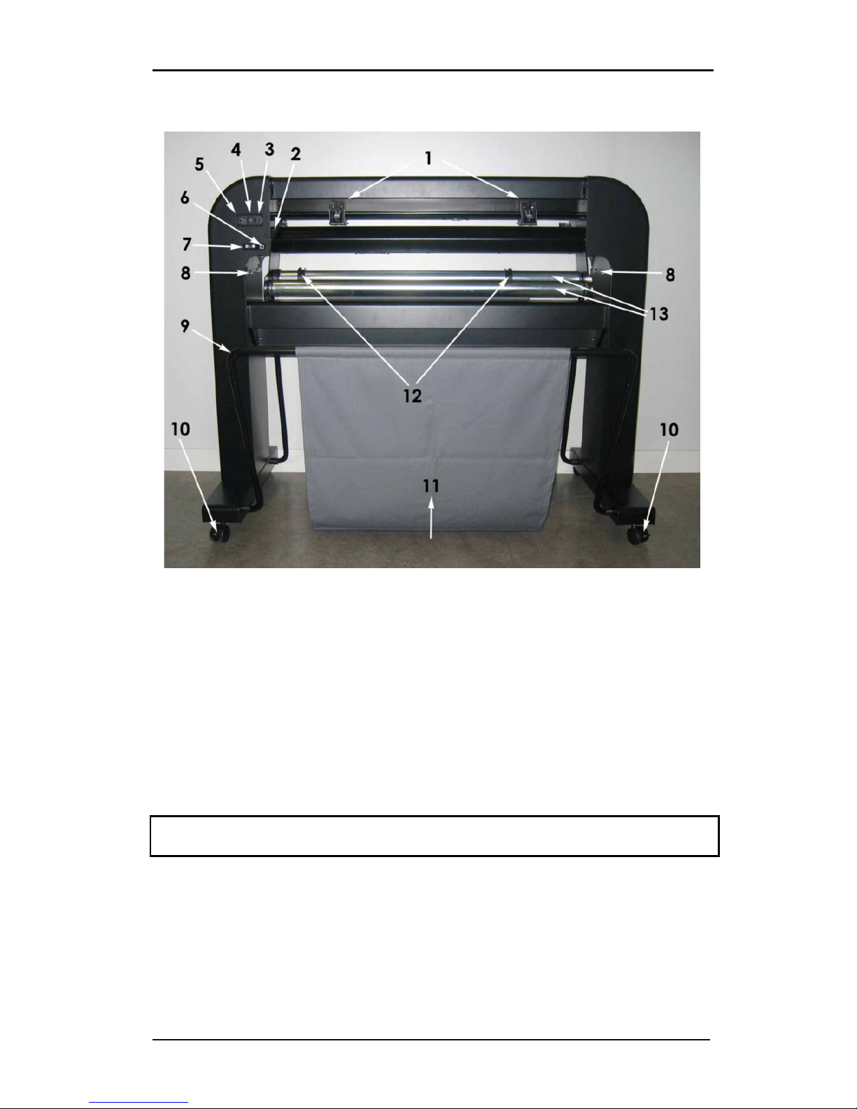
FIG 1-11
1-11 S CLASS™ CUTTER, REAR VIEW
1. Pinch rollers: The pinch rollers clamp the media to the drive system to ensure accurate
tracking. The S120(T) has one and the SS160(T) and S 140(T) have two extra pinch rollers
to ensure that wide media stays flat in the middle. The outer drive pinch rollers have a
selectable pressure; the extra rollers in the middle can be enabled or disabled. Do not
move the pinch roller assemblies while holding them from this side only.
2. Pinch roller lever: This lever is used to raise and lower the pinch rollers for media
loading.
3. The fuse box: The fuse is located at the right side of the power entry module. Check the
specification section to see which fuse is used in the S CLASS™ cutter.
CAUTION: For continued protection against risk of fire, replace only with the same type and
rating of fuse.
4. Power On/Off switch: This rocker switch, in the middle of the power entry module, sets
the cutter’s power to ON or OFF. To switch on the power, press the “I” side of the rocker
switch. To switch off the power, press the “O” side of the rocker switch.
5. AC power cord receptacle: It is located at the left-hand side of the power entry
module. The power-up procedure is explained in detail in Section 1.3. Always use a
power cord that was delivered with your cutter.
Page 19

S CLASS™ cutter User’s Manual
Setup 1-8
6. USB port: This interface is based on the standards specified in Universal Serial Bus
Specifications Revision 1.1. It allows a high-speed bi-directional communication
between the host computer and the cutter.
7. RS-232 port: This DB-9P connector provides serial bi-directional communication
between the cutter and a host computer.
8. Screws to secure the cutter base: Screws (3 left and 3 right) hold the cutter base to its
stand. All the screws must be properly tightened before using the cutter.
9. Tubes for media basket: Tubes in the back and front hold the media basket. They can
easily pulled outwards to put the basket in its place.
10. Casters: The casters on the stand are equipped with locking brakes. Once the cutter has
been moved to its new location, press the brakes with your foot to lock the casters.
11. Media basket: The stand and linen media basket come as standard equipment with all
S CLASS™ cutters.
12. Roll media guide bushes: The two flange guides serve to keep the media roll in place
when media is pulled from the roll.
13. Media support rollers: Rotating support rollers for the media roll.
Page 20
S CLASS™ cutter User’s Manual
Setup 1-9
1.3 Connecting the Cutter to the Mains
1.3.1 Grounding (“Earthing”)
CAUTION: An insulated ground conductor must be installed as part of the branch circuit that
supplies power to the wall outlet to which the cutter is connected. The ground conductor
must have the same size, insulation material and thickness as the grounded and ungrounded
branch circuit supply conductors, but the insulating seat should be green or green with
yellow striping.
The ground conductor described above must be grounded at the electrical distribution
board or, if power is supplied by a separate system, at the power supply transformer/motor
generator set.
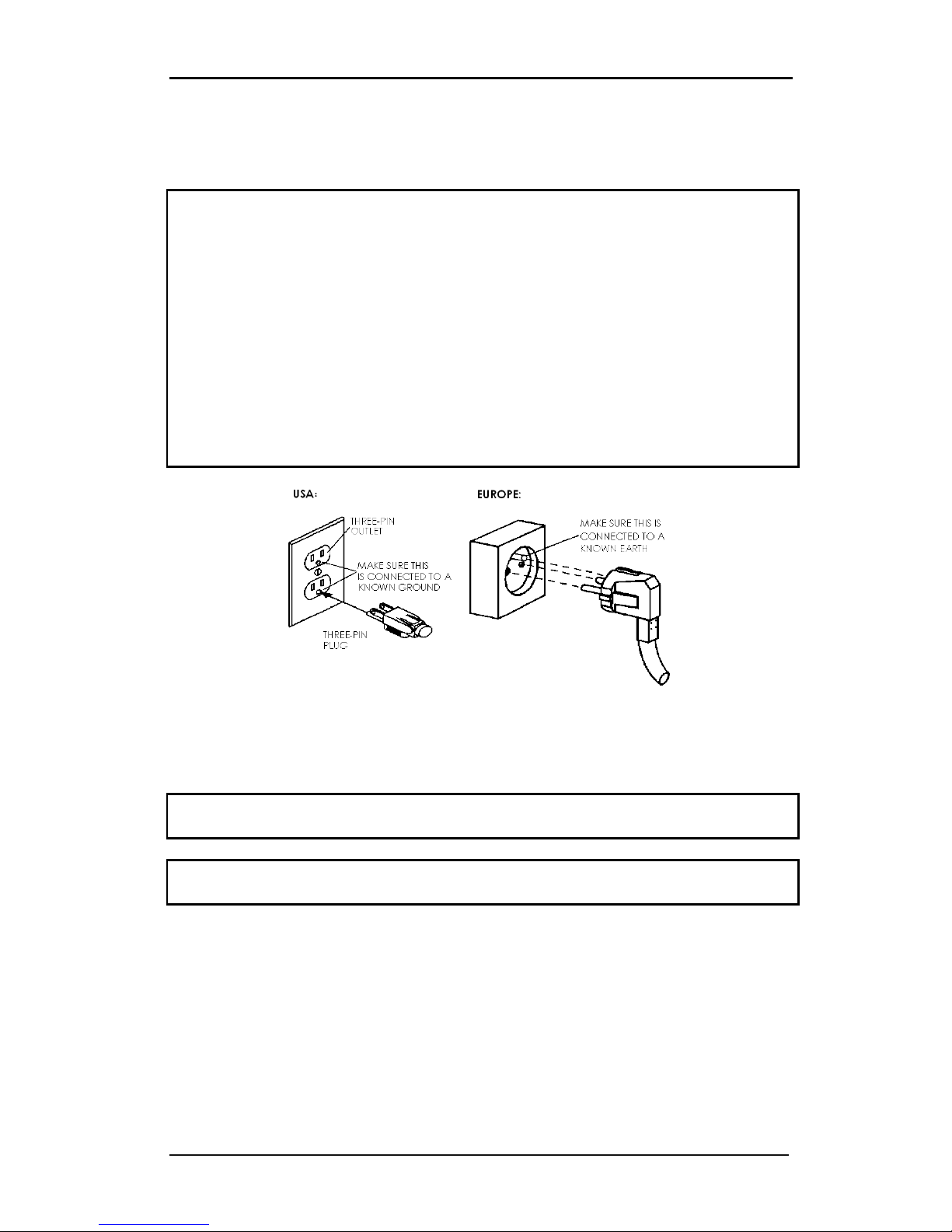
The wall sockets into which the cutter is plugged must be of the grounded type. The
grounded conductors serving the wall socket must be properly connected to the ground.
For emergency access, the cutter should be installed near the socket-outlet for easy access.
FIG 1-12
1-12 PROPERLY GROUNDED CONNECTION
1.3.2 Operating voltage
CAUTION: Before changing the fuse, make sure that the cutter is completely disconnected
from its power source.
CAUTION: For continued protection against risk of fire, replace only with the same type and
rating of fuse.
Fuse Rate: T2.0A, 250V SCHURTER SPT OR EQUIVALENT.
The power supply detects the line voltage and switches automatically between 110V and
230V.
Page 21
S CLASS™ cutter User’s Manual
Setup 1-10
1.3.3 Powering-on the cutter
CAUTION: Be sure the power switch is turned off before connecting the power cord (the “0”
side of the ON/OFF rocker switch should be pressed).
WARNING
KEEP FINGERS AND OTHER BODY PARTS AWAY FROM THE CUTTING AREA. THERE
ARE HAZARDOUS MOVING PARTS.
1. Plug the female end of the AC power cord into the receptacle located in the power
entry module on the cutter’s rear panel.
2. Plug male end of the AC power cord into a properly grounded wall socket.
3. Power on the cutter by pressing the “I” side of the ON/OFF rocker switch located on the
power entry module on the rear panel.
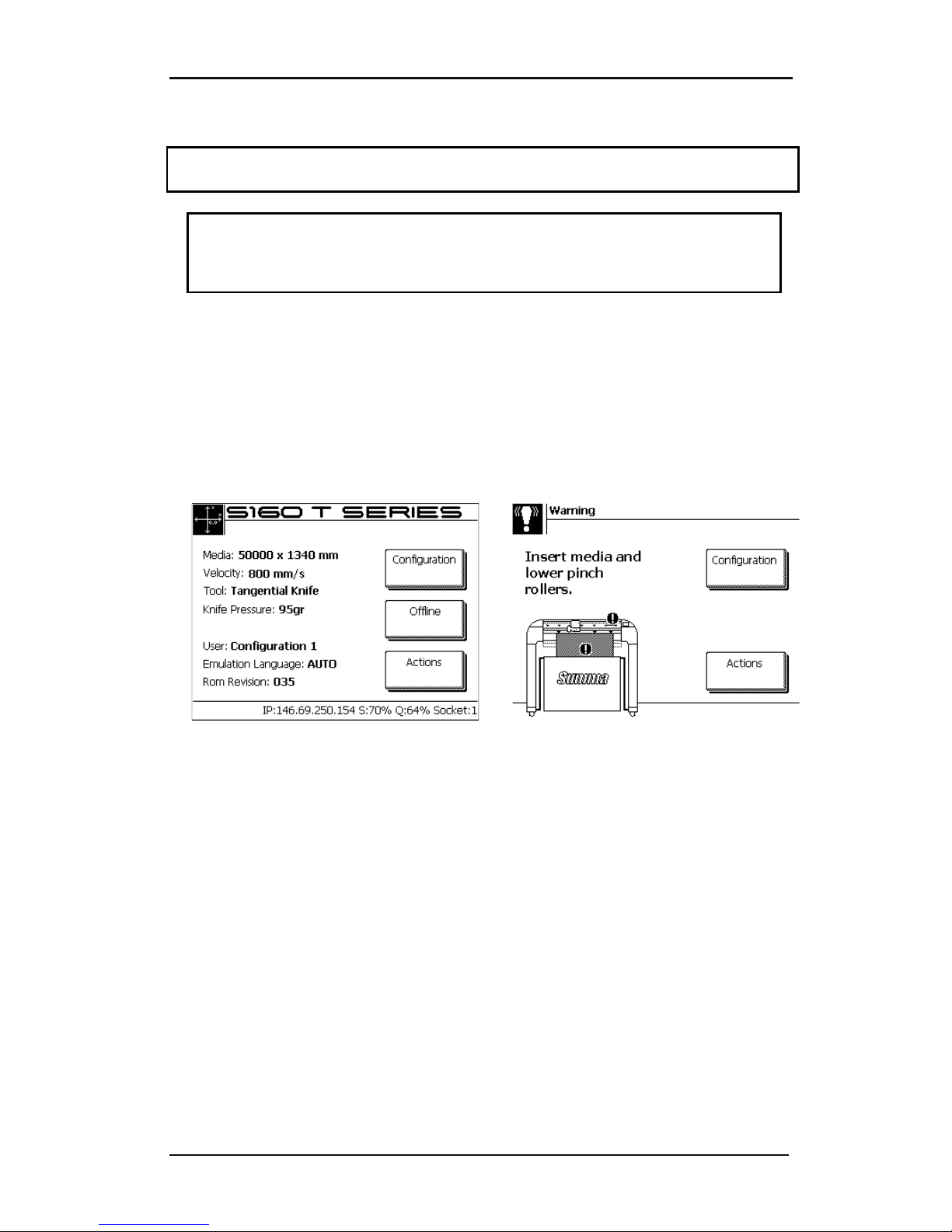
4. The touch screen will activate and the initialization process will begin. If media is
loaded, then the cutter will check size and load the media.
FIG 1-13
1-13 CUTTER IS LOADED AND READY
FIG 1-14
1-14 CUTTER IS READY NO MEDIA LOADED
Page 22

S CLASS™ cutter User’s Manual
Setup 1-11
1.4 Connecting the Cutter to a Computer
The S CLASS™ cutters support bi-directional USB and RS-232 connectivity. When both ports
are connected at the same time, the port that receives data first will remain active and the
other port will be deactivated.
A Wireless Ethernet connection is available as an option (factory installed).
1.4.1 USB connection
The USB cable should be 5 meters (16 feet) or less in length. The connector on the cutter
side of the cable should be USB series B 4-pin. The connector on the computer side of the
cable should be USB A 4-pin.
.
1.4.1.1 Connecting the S CLASS™ cutter to a PC using a USB cable
1. Power off the cutter.
2. Insert the S CLASS™ CD into the computer’s CD-ROM drive.
3. Let autoplay run autostart.
4. Choose language and click on install USB driver. Wait for the driver to install.
5. Connect one end of the USB cable to a USB port on the computer.
6. Connect the other end of the USB cable to the USB port on the back of the cutter.
7. Power on the cutter (see section 1.3.3) and return to the computer.
The Found New Hardware Wizard should appear on the computer screen and install the
USB driver.
8. Click “OK” and follow the instructions provided by the Wizard.
9. Restart the computer.
NOTE: When connecting a cutter to a computer for the first time using the USB cable, the
computer will detect the cutter and install the USB driver if the setup program was run. If the
setup program was not run prior to connection, then install the program while cutter is
connected and switched on. After that the program is run, the computer will detect a new
device and install the correct driver automatically.
NOTE: For connecting more than one cutter to one computer, see section on USB class
NOTE: It is recommended to use always the latest version of the driver. The Cd is made so
that it downloads the latest version automatically. If no internet connection is available, then
it is possible that the driver on the CD is outdated.
NOTE: When installing a cutter on Windows Vista or Windows 7, then make sure that the
user has administrative rights and that UAC is deactivated.
Page 23

S CLASS™ cutter User’s Manual
Setup 1-12
1.4.1.2 Connecting the S CLASS™ cutter to a Mac using a USB cable
Mac OS 8.5 to OS 9.2
1. Power off the cutter.
2. Connect one end of the USB cable to a USB port on the computer.
3. Connect the other end of the USB cable to the USB port on the back of the cutter.
4. Power on the cutter (see section 1.3.3) and return to the computer.
5. Insert the S CLASS™ CD into the computer’s CD-ROM drive.
6. Click on the “USB install driver” icon on the CD-ROM.
This will automatically install the driver and the Summa Port Mapper utility.
7. Remove the CD from the CD-ROM drive.
8. Restart the computer.
NOTE: If the cutter is connected to the computer before device installation, then the
computer will regard the cutter as an unknown device. The driver can be installed at any
time with or without the cutter connected.
Mac OSX
Most recent cutting software does not need a driver installation when a computer is
connected to the cutter. The software that controls the driver is built into the cutting
software.
Page 24

S CLASS™ cutter User’s Manual
Setup 1-13
1.4.2 RS-232 Connection
The RS-232 cable should be 5 meters (16 feet) or less in length. The connectors on both
sides are DB-9S type connectors. There is no need to install a device driver when connecting
a cutter with an RS-232 connection.
The parameters of the RS-232 connection must be set in either the properties of the COM
port in the device manager or in the cutting software program itself. Please refer to the
manual for the cutting software on how to set the parameters for the RS-232 connection
with the cutter.
Default settings of the RS-232 connection are listed in the table below.
Baud rate
9600
Data Bits
8
Parity
none
Stop Bits
2
Flow Control
Hardware or XON / XOFF
TABLE 1-1
1-1 DEFAULT RS-232 SETTINGS OF THE S CLASS™ CUTTER
Page 25
S CLASS™ cutter User’s Manual
Setup 1-14
1.4.3 Wireless Connection (optional)
The wireless connection has two options:
Wireless connection in a local area network (WLAN connection – network with a wireless
access point)
Wireless connection direct between the cutter and the computer (ad-hoc connection).
CAUTION:
Contains Transmitter Module FCC ID: U9R-W2SW0001.
CAUTION: The Wifi module can be operated in de European Union without restrictions
indoor, but cannot be operated in France outdoors.
1.4.3.1 Setting up the S CLASS™ cutter in a WLAN (Wi-Fi
®
compatible)
Wireless is a network connection. This means that the cutters can be integrated in a
network, such as printers normally are. So different people can drive the cutter from
different computers. It is also possible to drive different cutters from 1 computer through
wireless connection.
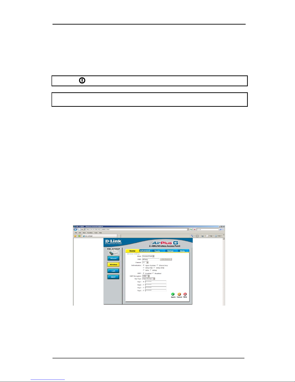
In order to setup the cutter, both the WLAN parameters (SSID – wireless access point name and security) and LAN parameters (IP configuration) have to be entered in the cutter.
Parameters for WLAN (access point):
• SSID (unique name for access point)
• Communication channel ( is assigned automatically)
• Security settings (none, WEP or WPA + password)
These parameters can be provided by the network administrator or can be checked with the
specific configuration utility for the access point. (a login name and password will be
needed – check with network administrator).
FIG 1-15
1-15 CONFIGURATION UTILITY FOR ACCESS POINT
Parameters for LAN (IP configuration):
• IP address
• subnetmask
Page 26
S CLASS™ cutter User’s Manual
Setup 1-15
Apart from the specific parameters mentioned above, there are two additional parameters
that the network administrator needs to provide.
If the access point is broadcasting; then the SSID can be seen on the cutter.
If the network has a DHCP server, then the LAN parameters can be assigned automatically.
Procedure to set up a cutter in a WLAN when the access point is broadcasting and with a
DHCP server:
The following procedure assumes a new cutter where the parameters for the wireless
connection have not been changed yet. If the parameters have already been changed, then
it is recommended to factory default the wireless parameters first (see Wireless:)
1. Power on the cutter.
2. Press .
The main menu will appear on the screen.
3. Press .
The settings menu will appear on screen.
4. Press .
The communication menu will appear on screen.
5. Press .
The wireless menu will appear on screen.
6. Press .
The WLAN menu will appear on screen.
7. Press .
The cutter will scan for wireless access points and show them on screen.
8. Use or to choose the correct access point.
The chosen access point (inverse) will change.
9. Press to confirm.
The WLAN menu will appear on screen.
10. Press .
Page 27
S CLASS™ cutter User’s Manual
Setup 1-16
The security menu will appear on screen.
11. Use or to choose the correct security method.
The chosen security method (inverse) will change.
12. Press to confirm.
The WLAN menu will appear on screen.
13. Press .
The Configure menu will appear on screen.
14. Use or to go to key 1.
‘ key 1’ will become inverse.
15. Press to enter the password.
A mobile phone like keypad will appear on screen .
16. Enter the password. If there are already asterix’s visible in the top line, then clear them
first by pressing until they are all gone.
The password will appear on screen .
17. Press three times, then press .
The cutter will prompt the user to reboot the machine.
18. Do so.
After a reboot the cutter will show the assigned IP address on the bottom line of the screen.
This address is has to be used when installing the cutter in the cutting software.
Alternate procedure when the access point is not broadcasting:
The procedure is analogue to the procedure above.
Steps 6 -> 8 need to be left out.
After that the password is entered, enter the SSID in the same way as ‘key 1’ was entered.
Alternate procedure when there is no DCHP server:
In this case an IP address and subnet mask needs to be provided by the network
administrator.
The procedure is analogue to the procedure above.
Stop before step 16.
Then continue with procedure below:
Page 28
S CLASS™ cutter User’s Manual
Setup 1-17
16. Press two times.
The communication menu will appear on screen.
17. Press .
The LAN menu will appear on screen.
18. Press
.
The DHCP menu will appear on screen.
19. Use or to set DHCP to on if necessarry.
On (inverse) will change.
20. Press to confirm.
The LAN menu will appear on screen.
21. Press .
The Configure menu will appear on screen.
22. Press to enter the first the IP address.
A mobile phone like keypad will appear on screen .
23. Enter the IP address. An IP address consists out of four 3-digit numbers. If the IP address,
received from the network administrator, has one or more numbers that have less than
a 3-digit number, then precede them by as many 0’s as necessary to get to a 3 digit
number.
The IP address will appear on screen .
24. Press .
The Configure menu will appear on screen.
25. Press to enter the subnet mask.
‘ subnet mask’ will become inverse.
26. Press to enter the first the subnet mask.
A mobile phone like keypad will appear on screen .
Page 29
S CLASS™ cutter User’s Manual
Setup 1-18
27. Enter the subnet mask. The subnet mask consists out of four 3-digit numbers. If the
subnet mask, received from the network administrator, has one or more numbers that
have less than a 3-digit number, and then precede them by as many 0’s as necessary to
get to a 3-digit number.
The subnet mask will appear on screen .
28. Press three times, then press .
The cutter will prompt the user to reboot the machine.
29. Do so.
After a reboot the cutter will show the assigned IP address on the bottom line of the screen.
This address is has to be used when installing the cutter in the cutting software.
Procedure when the wireless network uses MAC filtering:
Some wireless networks have an extra security feature called Mac address filtering. This
means that the network allows only known devices.
If the wireless network has MAC filtering enabled (check with network administrator), then
the MAC address has to be added to the list of accepted MAC addresses in the configuration
menu of the wireless access point before any settings are changed on the cutter. Following
procedure describes how to retrieve the MAC address:
1. Power on the cutter.
2. Press .
The main menu will appear on screen.
3. Press
.
The first part of the tests and setup menus will appear on screen.
4. Press .
The second part of the tests and setup menu will appear on screen.
5. Press .
The ROM revision will appear on screen
6. The last line on screen is the MAC address of the wireless module. Give this number to
the network administrator so that access can be granted for the cutter to the wireless
network.
Page 30
S CLASS™ cutter User’s Manual
Setup 1-19
1.4.3.2 Connecting the S CLASS™ cutter ad hoc.
Ad-hoc networks connect to wireless devices with same SSID (network name) and
broadcasting on the same communication channel, with each other.
Following settings have to done for every device who is member of that ad-hoc network:
• Set same SSID on each device.
• Set same communication channel on each device.
• Set Unique IP address fro each device within same subnet (DHCP is not available).
• Set same subnet on each device.
• If one device is connected to the internet (and internet connection sharing is on for
that device), set the IP address of this device as gateway on each other device.
Setup parameters of the cutter:
The following procedure assumes a new cutter where the parameters for the wireless
connection have not been changed yet. If the parameters have already been changed, then
it is recommended to factory default the wireless parameters first (see Wireless:)
1. Power on the cutter.
2. Press .
The main menu will appear on the screen.
3. Press .
The settings menu will appear on screen.
4. Press .
The communication menu will appear on screen.
5. Press .
The wireless menu will appear on screen.
6. Press .
The LAN menu will appear on screen.
7. Press
.
The DHCP menu will appear on screen.
8. Use or to set DHCP to off.
Page 31
S CLASS™ cutter User’s Manual
Setup 1-20
Off (inverse) will change.
9. Press to confirm.
The LAN menu will appear on screen.
10. Press .
The wireless menu will appear on screen.
11. Press .
The WLAN menu will appear on screen.
12. Press .
The mode menu will appear on screen.
13. Use or to choose the correct mode (Ad-hoc).
The chosen mode (inverse) will change.
14. Press to confirm.
The WLAN menu will appear on screen.
15. Press three times, then press .
The cutter will prompt the user to reboot the machine.
16. Do so.
This procedure will have set the WLAN and LAN parameters to its default values for an Adhoc network.
Default values are:
SSID: SummaCutter
Channel: 9
Security: off
IP address: 192.168.1.100
Subnetmask: 255.255.255.0.
If needed, those values can be changed in the configuration menus of the WLAN and LAN
menu, but it is not recommended to do so.
If more then one cutter is setup in the ad-hoc network, then it is just the IP address needs to
be changed so that each cutter has an unique number. Only the three last numbers may be
changed to an unused number in the network.
Page 32
S CLASS™ cutter User’s Manual
Setup 1-21
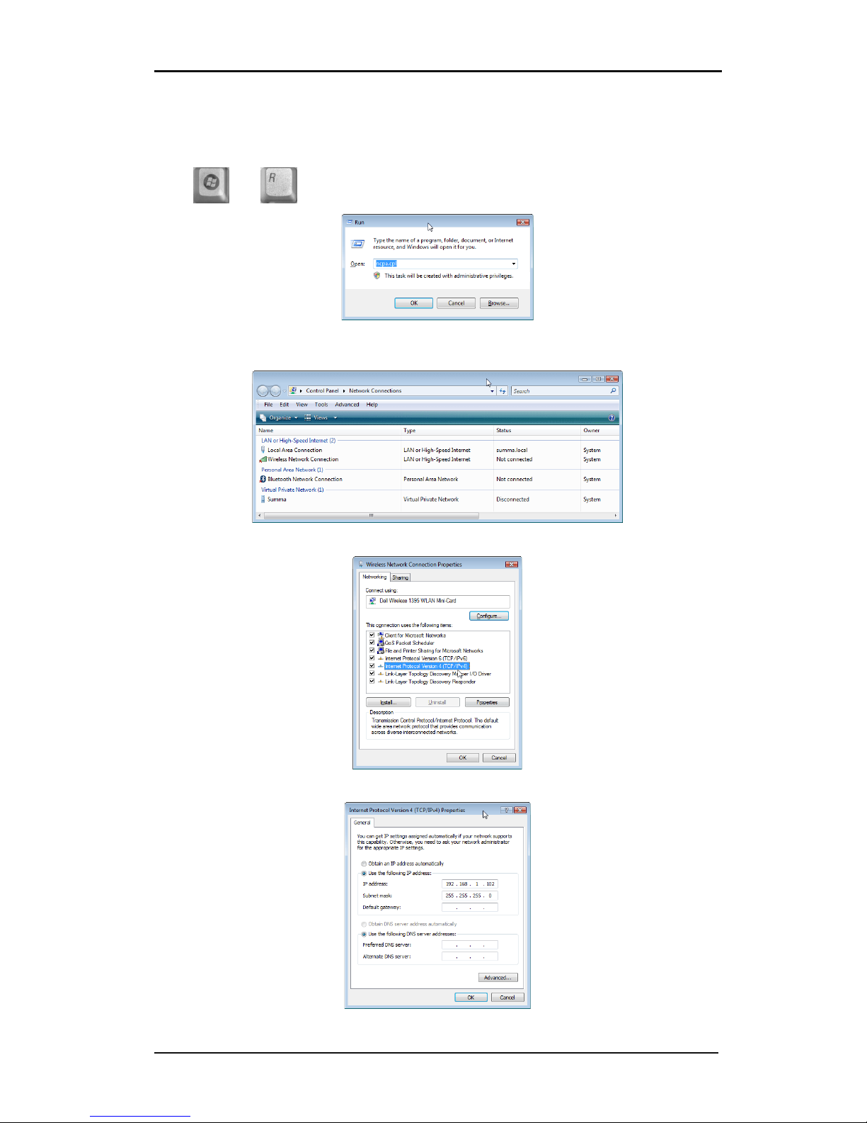
Computer setup for ad-hoc connection:
Setup PC LAN parameters:
Press and . A windows will open fill in ncpa.cpl and click OK.
A window will open with available network connections. One of them will be the wireless
connection.
Right click the wireless connection and select properties.
Select TCP/IP protocol (version 4 if there is more then 1) and click on Properties.
Page 33
S CLASS™ cutter User’s Manual
Setup 1-22
Select ‘Use the following IP address’. Choose as subnet mask 255.255.255.0 and define a
unique address fort this network. Click OK. Close the net properties window.
The LAN parameters are now set. The WLAN parameters need to be set now. WLAN
parameters can be set with either the software delivered with the wireless device. These
parameters can also be set with Windows. The following procedure describes how this is
done for Windows XP and Windows Vista.
Setting WLAN parameters for Windows XP:
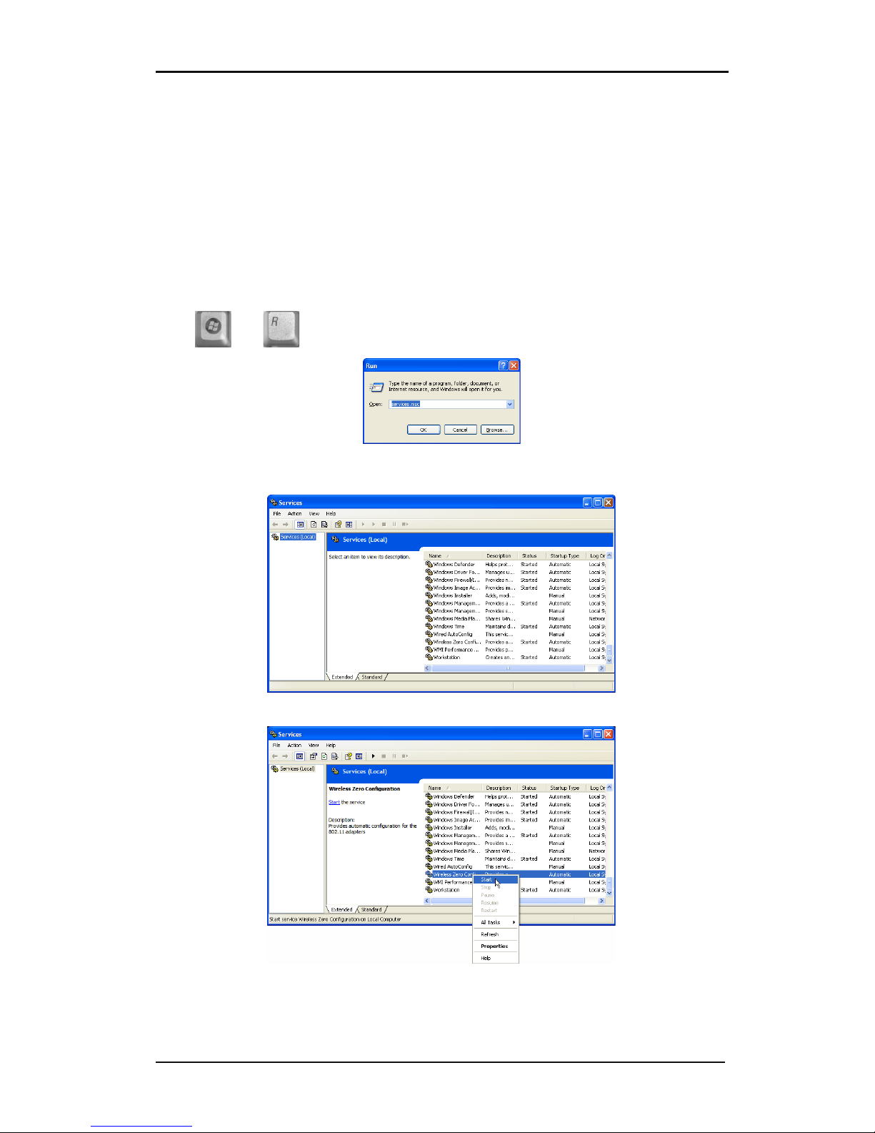
A pre-installed Windows service ‘Wireless zero configuration’ is needed for installation in XP.
First check if the service ‘Wireless zero configuration’ is started, if not start it.
Press and . A windows will open fill in services.msc and click OK.
In the new window scroll down to the Wireless zero configuration service. Check if is
started.
If it not started, then select it, right click and start it.
Close the services Window.
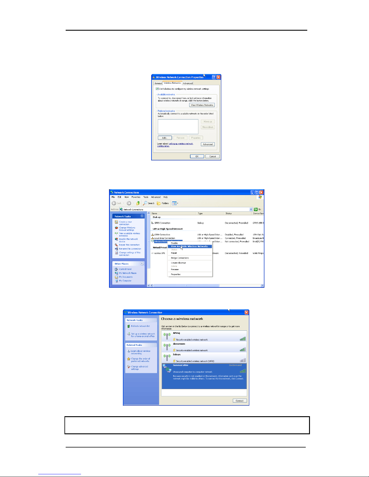
Go to the Network connection Window. If it was already closed, then open it again with the
run command and ncpa.cpl.
Page 34
S CLASS™ cutter User’s Manual
Setup 1-23
Right click the Wireless network and click on properties. Then click on Wireless Networks
(second tab). Make sure that the option ‘Use Windows to configure my wireless network
settings’ is checked. Click OK.
Go to the Network connection Window. If it was already closed, then open it again with the
run command and ncpa.cpl.
Right click the Wireless network and click on view available networks.
Choose the SummaCutter in the list and click on connect. If Windows give a security
warning, then ignore it.
CAUTION: The Wireless zero configuration can sometimes come into conflict with control
software of the wireless adapter of the computer. Make sure only one runs.
Page 35
S CLASS™ cutter User’s Manual
Setup 1-24
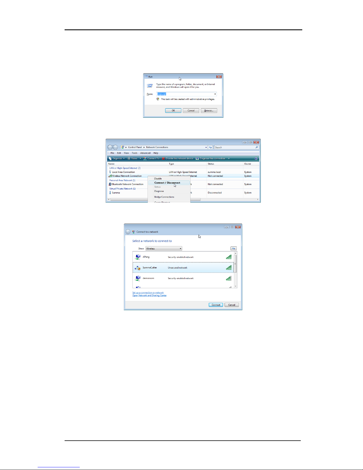
Setting WLAN parameters for Windows Vista:
Go to the Network connection Window. If it was already closed, then open it again with the
run command and ncpa.cpl.
Right click the Wireless network and click on connect/disconnect.
A window with the available wireless networks will open. Choose SummaCutter in the list
and click on connect. If Windows give a security warning, then ignore it.
Page 36
S CLASS™ cutter User’s Manual
Setup 1-25
1.4.3.3 Webserver
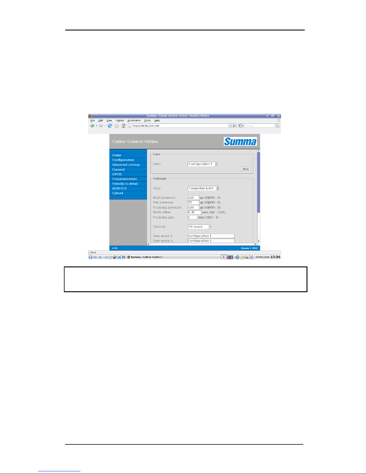
The cutter has an internal web server.
By typing the IP address (e.g. http://192.168.1.100 ) in to internet explorer address bar, a
simplified online version of Summa cutter Control is started, which is accessible from any
computer, on any platform (e.g. windows, Macintosh, Linux).
Some combinations OS – browser may not work, if so then either reload the page partially
or install another internet browser.
Note: Some settings in the firewall or in the internet connection setup might prevent the
use of the internal webserver of the cutter. Contact the network administrator if this is the
case.
Page 37
S CLASS™ cutter User’s Manual
Setup 1-26
1.5 Loading Media
The following procedures apply mainly to the use of roll media. If you are using sheets,
there are two options:
For long sheets, roll up the sheet so that the alignment is identical to that of a roll.
For short sheets, the alignment is not so important. If the sheet is cut off perpendicularly, it
can be aligned to the front border.
1.5.1 Pinch roller positioning
Proper movement of the media will only occur if the media is driven by the two outer pinch
rollers that are correctly located over two drive sleeves.
The pinch rollers are lowered or raised simultaneously by means of the pinch roller lever
arm located on the right-hand side of the cutter. The pinch rollers must be lifted to allow
vinyl loading, during which the media is fed from the rear of the cutter to the front. When
raised, the pinch rollers can be moved manually to the left or the right along the pinch roller
shaft.
CAUTION: Always make sure that the pinch rollers are fully raised before sliding them to
the left or right.
Always hold the assembly at the side of the pinch roller to move it from left to right; do not
reposition pinch roller by holding the assembly at the rear of the machine.
The pinch rollers MUST be positioned correctly and lowered onto the media before an
automatic load sequence is initiated. Make sure that all the pinch rollers are positioned
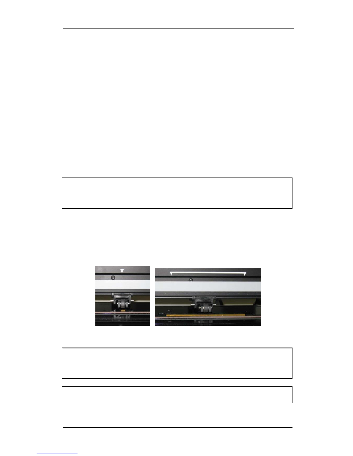
above a drive sleeve. The outer left pinch roller should be positioned in one of the detents
(click position), just under a white triangular label. The outer right pinch roller should be
positioned somewhere over the long drive sleeve, click positions are located at the edges of
the sleeve (area marked with a white triangular label).
FIG 1-16
1-16 POSITION PINCH ROLLERS
ATTENTION: Always leave the pinch rollers in the “up” position when the cutter is not in
use. Leaving the pinch rollers in the “down” position for a long time will result in a flat spot
in the pinch rollers, which will seriously [negatively] affect tracking performance and
cutting quality.
NOTE: When the pinch rollers are raised during a job, then the cutter will immediately stop
and after a second move the carriage to the right side.
Page 38
S CLASS™ cutter User’s Manual
Setup 1-27
1.5.2 Pinch roller pressure setting
The S CLASS™ cutters are equipped with selectable pinch wheel pressure. The pressure can
be set to “standard” or “low.” The pressure can be changed with the pinch rollers in the “up”
position or in the “down” position.
The earlier models have a system which can be switched in and out at all times.
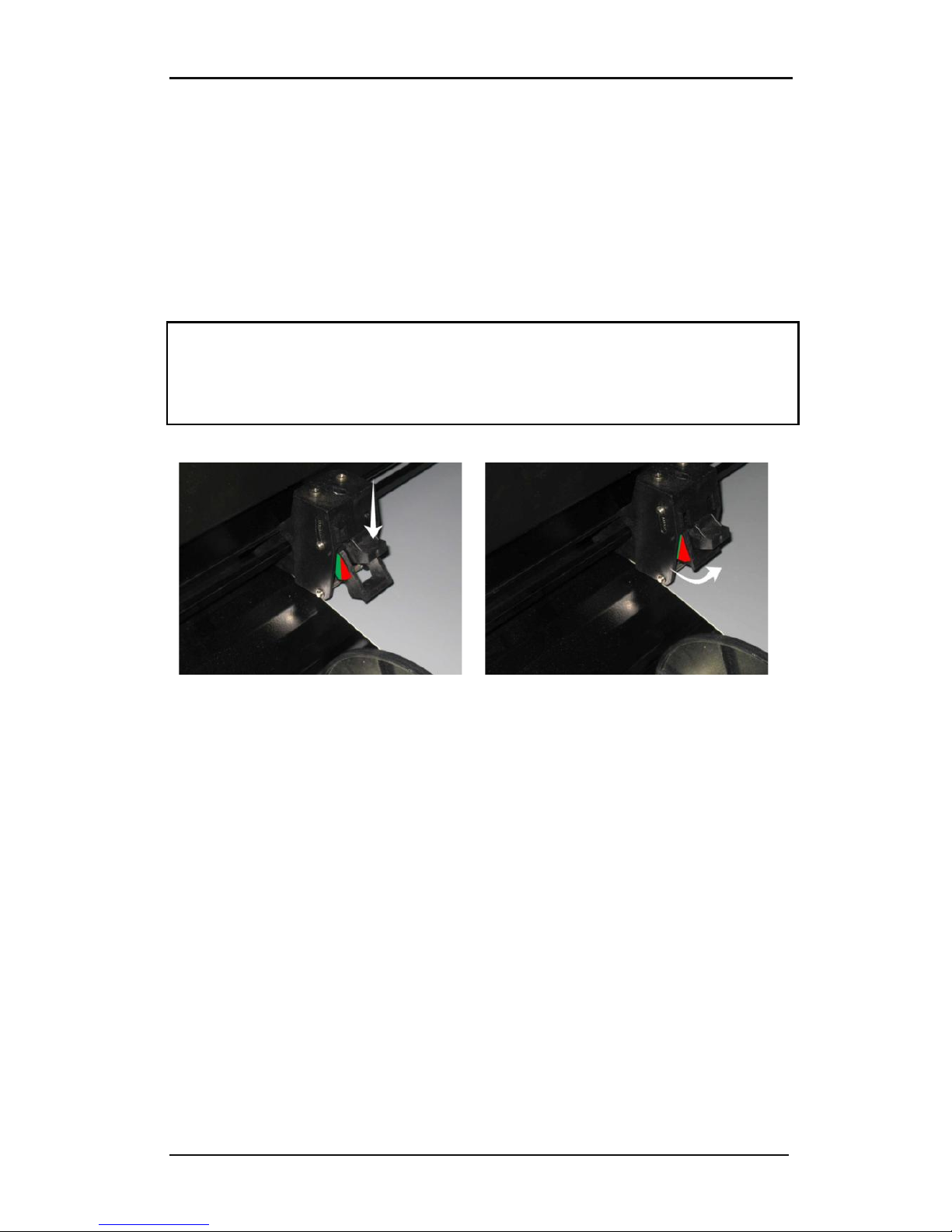
They can be recognized by the green/red sticker on the back of the outer pinch roller
assemblies.
1.5.2.1 Changing pressure on older models
CAUTION: Always make sure the outer left pinch roller pressure is set the same as the outer
right pinch roller pressure.
There is a label on the assembly that makes it easy for the user to check the selected pinch
roller pressure.
It is best to change pressure when the pinch rollers are in the “up” position.
FIG 1-17
1-17 STANDARD PRESSURE
FIG 1-18
1-18 REDUCED PRESSURE
Standard pressure: the two colors on
the label are clearly visible. The
pressure can be reduced by pushing
on the plastic part as shown in the
picture. If pressed hard enough, the
pinch roller assembly should click in
its new position.
Reduced pressure: only one color is
distinctly visible. The pressure can be
set to “standard” by pulling the
bottom part of the pinch roller
assembly upwards. If pulled far
enough, the pinch roller assembly
should click in its new position.
The S120, the S140 and the S160 are equipped with extra pinch rollers to guide wide media.
These pinch rollers can be enabled or disabled by following the same steps used to change
the pressure on the outer pinch rollers.
Page 39
S CLASS™ cutter User’s Manual
Setup 1-28
1.5.2.2 Changing pressure on the new models
With the later models, the change in pressure can only be done when the pinch rollers are
in the down position. When reduced pressure is needed, then it is advised to set autoload to
‘ASK’. Then the cutter will not start to load the vinyl when the pinch rollers are set down or
when it is switched on. On the touch screen there will be a message, giving the user time to
change the pressure on the pinch rollers.
NOTE: Each time the pinch rollers are raised, the pressure is automatically set back to full
pressure.
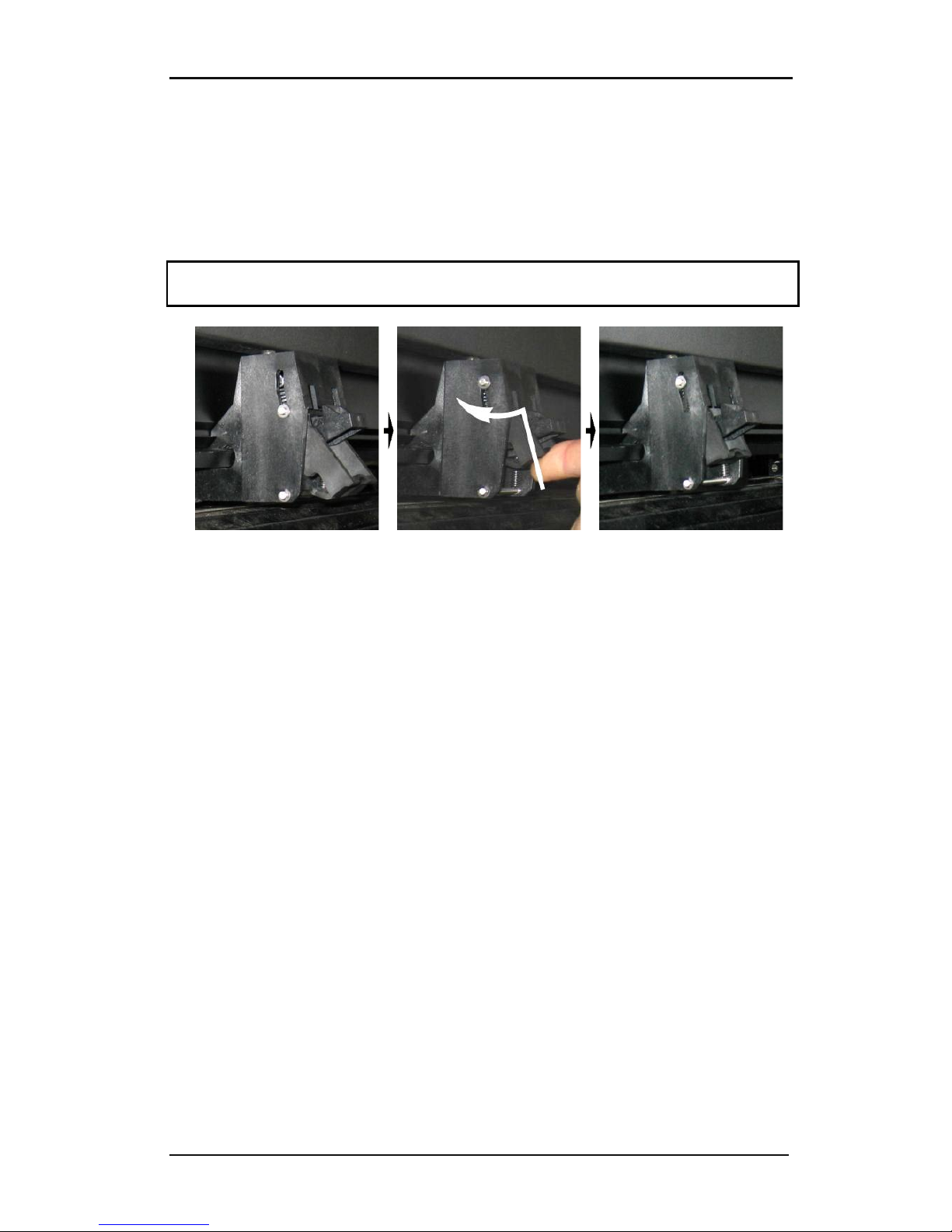
FIG 1-19
1-19 REDUCING PRESSURE
To work with reduced pressure do the following:
1. Set AUTOLOAD to ASK (see section on Autoload:).
2. Load media in the cutter (see section on Media load procedure).
3. Push the lever of the two outer pinch rollers upwards and inwards (toward the
machine) – see figure above.
Page 40
S CLASS™ cutter User’s Manual
Setup 1-29
1.5.3 Loading media
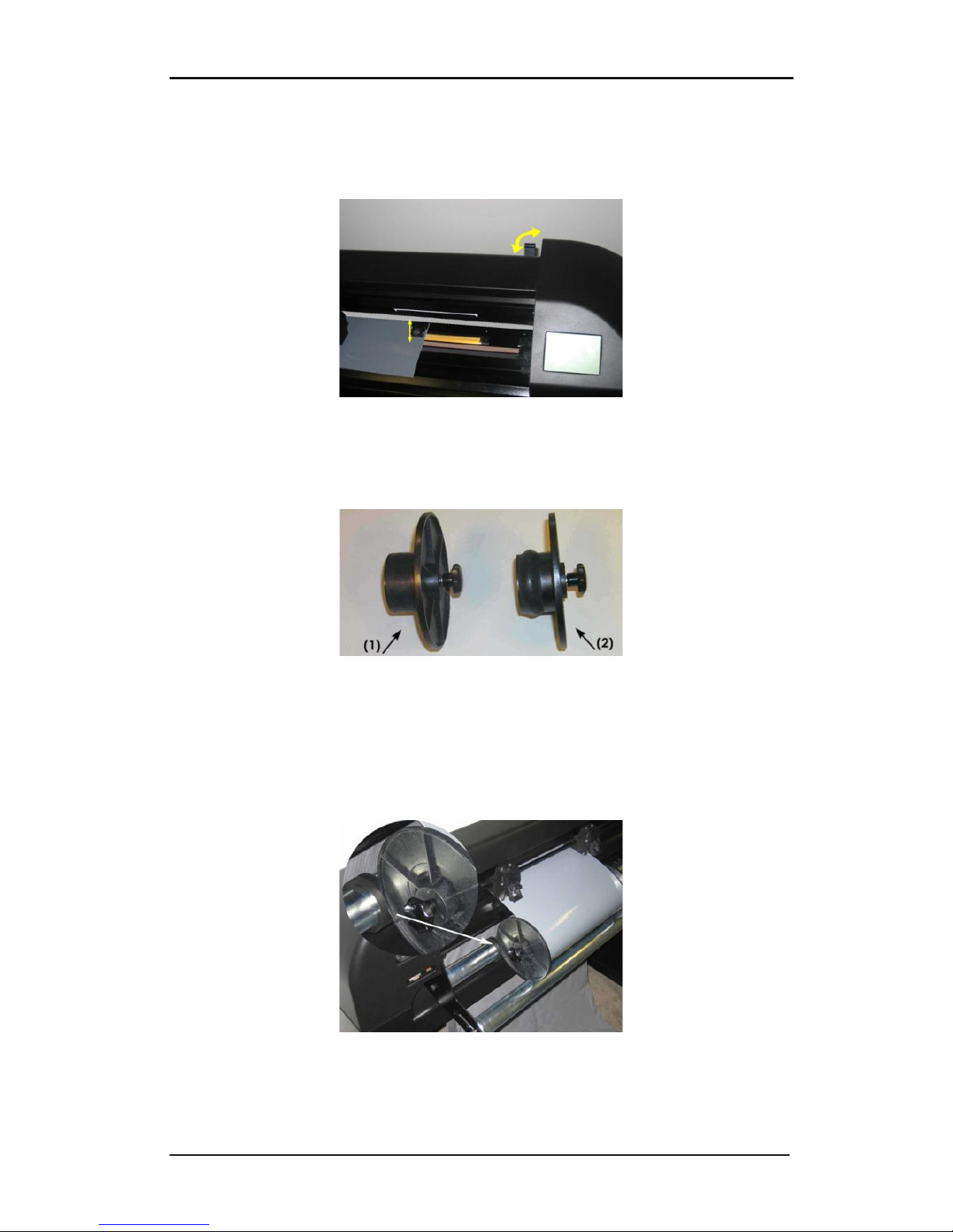
1. Raise the pinch rollers by means of the pinch roller lever arm, which is located on the
right-hand side of the cutter, next to the touch panel.
FIG 1-20
1-20 PINCH ROLLER LEVER
2. Loosen the knobs on the two media flanges. The following illustration shows a loosened
flange (1) and a tightened flange (2).
FIG 1-21
1-21 MEDIA FLANGES
3. Insert a loosened flange into one end of the media roll and tighten the knob. Verify that
the flange is secure. Then do the same on the other side of the roll.
4. Place the flange-equipped roll on the media supply rollers. Set the flanges inside the
groove of the flange guide. The flange guides can be moved laterally on the roller.
FIG 1-22
1-22 POSITION MEDIA FLANGE ON CUTTER
Page 41
S CLASS™ cutter User’s Manual
Setup 1-30
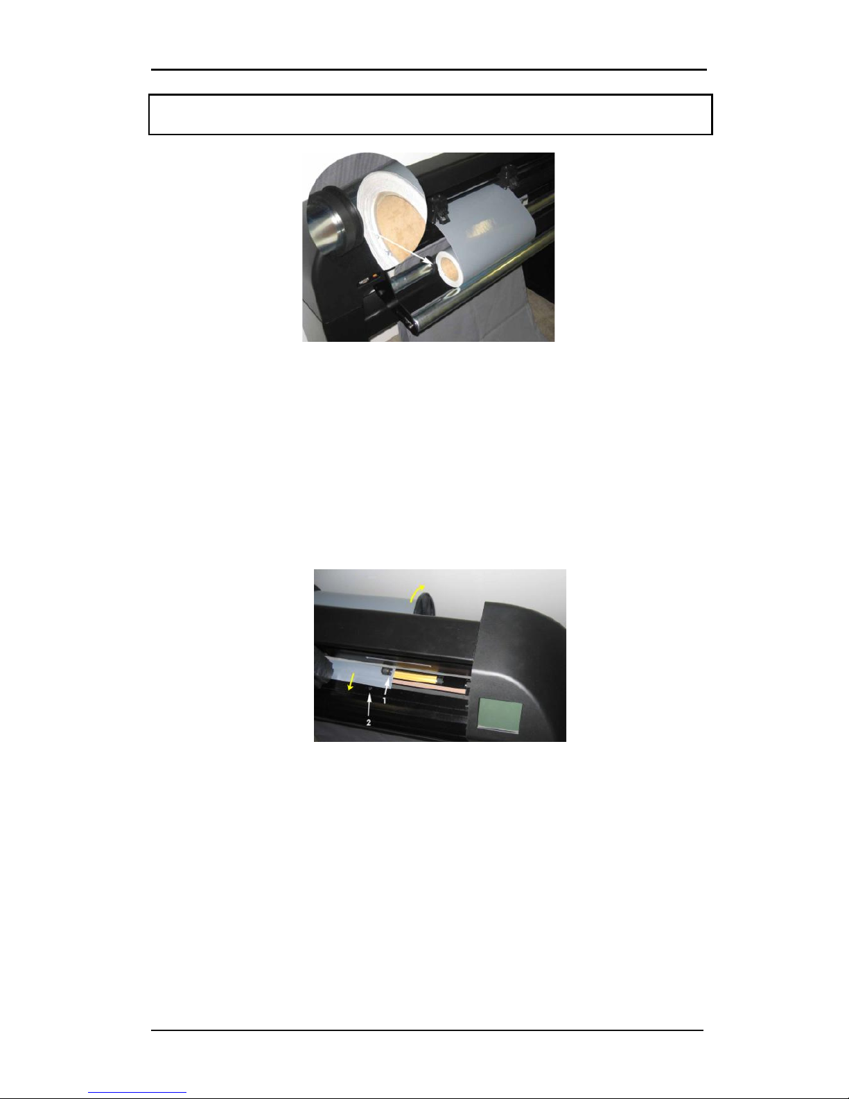
NOTE: If the flanges are not used (not recommended – tracking is not guaranteed), then
make sure that the roll is caught between the two flange guides.
FIG 1-23
1-23 FEEDING ROLL MEDIA WITHOUT USING MEDIA FLANGES
5. Start feeding the media from the rear of the machine. Pass the media underneath the
pinch rollers towards the front of the machine.
6. Position the left media edge on the left-most drive sleeve and check whether the right
media edge is positioned over the long drive sleeve. Then position the left and right
pinch rollers.
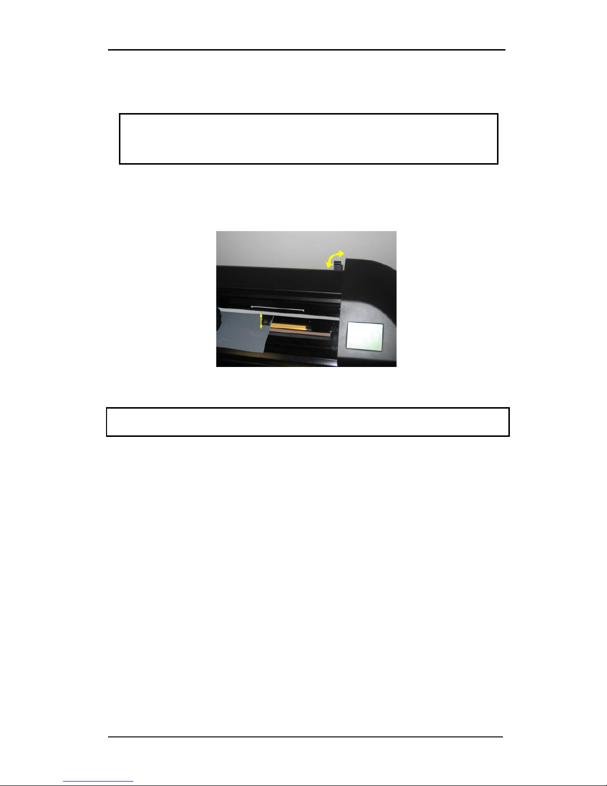
The pinch rollers should be positioned over the drive sleeves about 3 to 15 mm (0.1” to
0.6”) away from the media’s outer edges (1). Then pull on the media while holding the
flange at the back so the media is tight. Make sure the front media sensor is covered (2).
FIG 1-24
1-24 MEDIA POSITION
In circumstances where the above procedure does not work, because the media is too
narrow to reach the long drive sleeve, try positioning the left media edge over the
second left drive sleeve and position the right media edge somewhere over the long
drive sleeve. Continue moving the left pinch roller toward the long drive sleeve until
both pinch rollers are in their designated position and directly over the edges of the
vinly.
In all cases, both edges of the media must cover a drive sleeve. If this is not the case,
reposition the roll of material to cover the drive sleeve.
Page 42
S CLASS™ cutter User’s Manual
Setup 1-31
7. Make sure that the media follows a straight path from the roll of material. To accomplish
this, slide the media roll and flange guides from the left to the right along the media
support rollers.
WARNING
KEEP FINGERS AND OTHER BODY PARTS AWAY FROM THE CUTTING AREA. THERE
ARE HAZARDOUS MOVING PARTS.
8. Lower the pinch roller lever to press the media firmly against the drive sleeves. After
one second the tool carriage automatically moves from the right to the left to sense the
usable media width.
FIG 1-25
1-25 PINCH ROLLER LEVER
NOTE: It is not recommended to unroll the media manually from the roll. The cutter will
unroll the media automatically during the load sequence.
9. The positioning and routing of sheet material is identical to that of roll media.
10. The cutter is now ready.
Page 43

S CLASS™ cutter User’s Manual
Setup 1-32
1.5.4 Media load procedure
CAUTION: Do not place any objects in front of, or behind, the cutter that could interfere with
cutter operation. Make sure the media is free to move forward and back. Keep hands, hair,
clothing and jewelry away from moving parts.
While the cutter is on, it will automatically start executing a minimal loading procedure as
soon as the pinch rollers are lowered. The load procedure will also start when the cutter is
switched on while media is already in the machine and the pinch rollers are in the “down”
position (this is not recommended). Always keep the pinch rollers in the up position while
the cutter is not being used.
The minimal loading procedure consists of:
A media width measurement.
Media is unwound over a length equal to the width measured between the outer
two pinch rollers.
A simultaneous 45° axial move of the drive drum (sleeves) and cutting head.
After that, the cutter is ready to receive files from the computer.
When receiving a job from the computer, the cutter will automatically pull the required
media from the roll. It does this in steps and the length of the vinyl used is equal to a
number of times the measured width of the media.
IMPORTANT: Tracking of longer signs is only guaranteed when the full load procedure is
performed!
Full media load procedure:
WARNING
Each keystroke can initiate an internal test or movement of head or media.
Keep fingers and other body parts away from the cutting area.
There are hazardous moving parts.
Page 44
S CLASS™ cutter User’s Manual
Setup 1-33
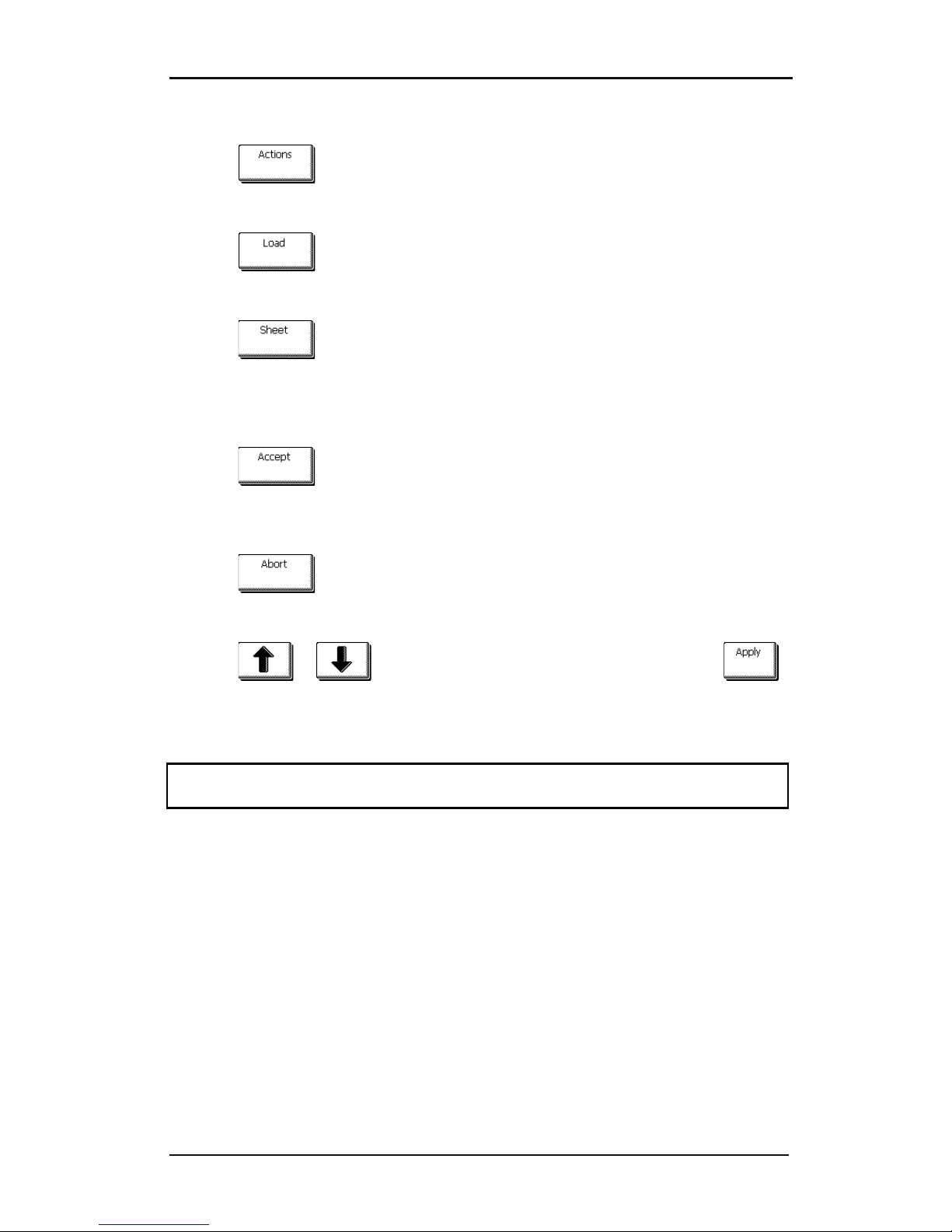
Loading a sheet.
1. Press .
The actions menu will appear on screen..
2. Press .
A message will appear letting the user choose between roll and sheet.
3. Press
.
The cutter will immediately start to load the sheet. It measures the width and loads a certain
length of media, or until the end of the media is encountered. The user will then be prompted
to accept the length or not.
4. Press to accept the length or go to step 5.
The cutter will now complete the loading sequence and then come online and will be ready
to receive data. The loading sequence conditions the edges of the vinyl for a given length.
5. Press .
Two arrows will appear on the touch screen.
6. Press or until the required media length appears, then press .
The cutter will now complete the loading sequence. After that, the cutter will come online
and will be ready. The length of the job it can cut is limited to the loaded length.
NOTE: If the rear media sensor detects the end of the media, then the cutter will complete
the loading sequence without any input from the user.
Page 45
S CLASS™ cutter User’s Manual
Setup 1-34
Loading a roll.
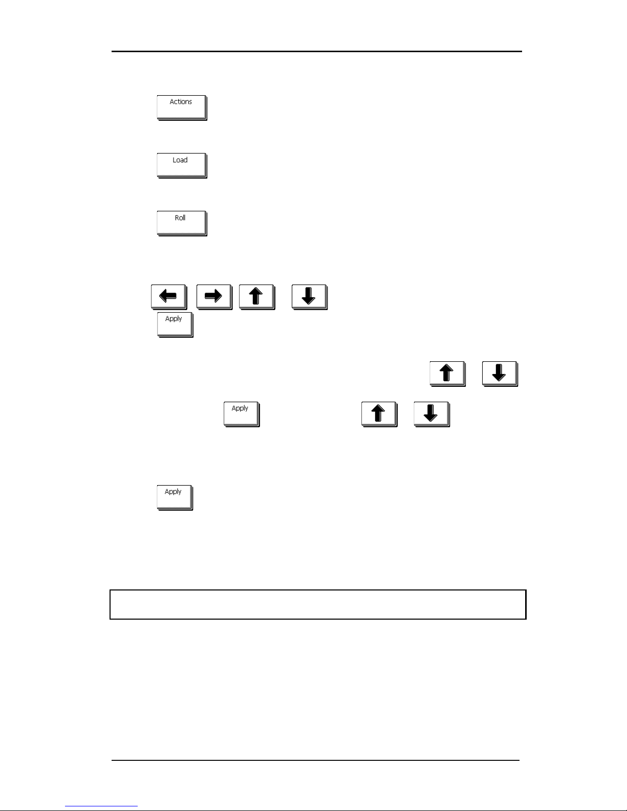
1. Press .
The actions menu will appear on screen.
2. Press .
A message will appear letting the user choose between roll and sheet.
3. Press .
Four arrows will appear, together with an “apply” button. The status is visible in the middle
of the right-hand side of the screen.
4. Use , , or to reposition the origin, if necessary. Then
press .
Two arrows will stay on the screen with which the necessary length can be loaded.
5. The media length needed for the task can be entered by pressing or
and thus then loading the needed length. Or the needed length for the job can be
entered by pressing and then by pressing or to change the
value of the default length to load.
Depending on the manner chosen for entering the needed length of the job, the cutter will
either load the length or display the chosen length on screen.
6. Press
The cutter will now complete the loading sequence. Then the cutter will come online and will
be ready. The length of the job it can cut is limited to the actual length of the media that is
left on the roll. The cutter will always assume a full roll, thus it will use 50000mm (1982
inches) on the status screen.
When the built-in media sensors detect the end of the roll, the cutter will complete the
loading sequence and display the media size on the status window.
Page 46
S CLASS™ cutter User’s Manual
Setup 1-35
Extended load.
The function extended load makes it possible to define the limits of the Y axis so that the
cutter can cut outside the pinch rollers. Media has to loaded before this function can be
used.
1. Press .
The actions menu will appear on screen.
2. Press .
A message will appear letting the user choose between roll and sheet.
3. Press .
Two arrows will appear, together with an “apply” button.
4. Use or to reposition the right Y-axis limit. Then press .
Two arrows will stay on the screen, the tool carriage will move to the left Y-axis limit.
5. Use or to reposition the left Y-axis limit. Then press .
The cutting area in the Y-axis has now been redefined.
Note: Tracking is not guaranteed when using this mode.
Page 47
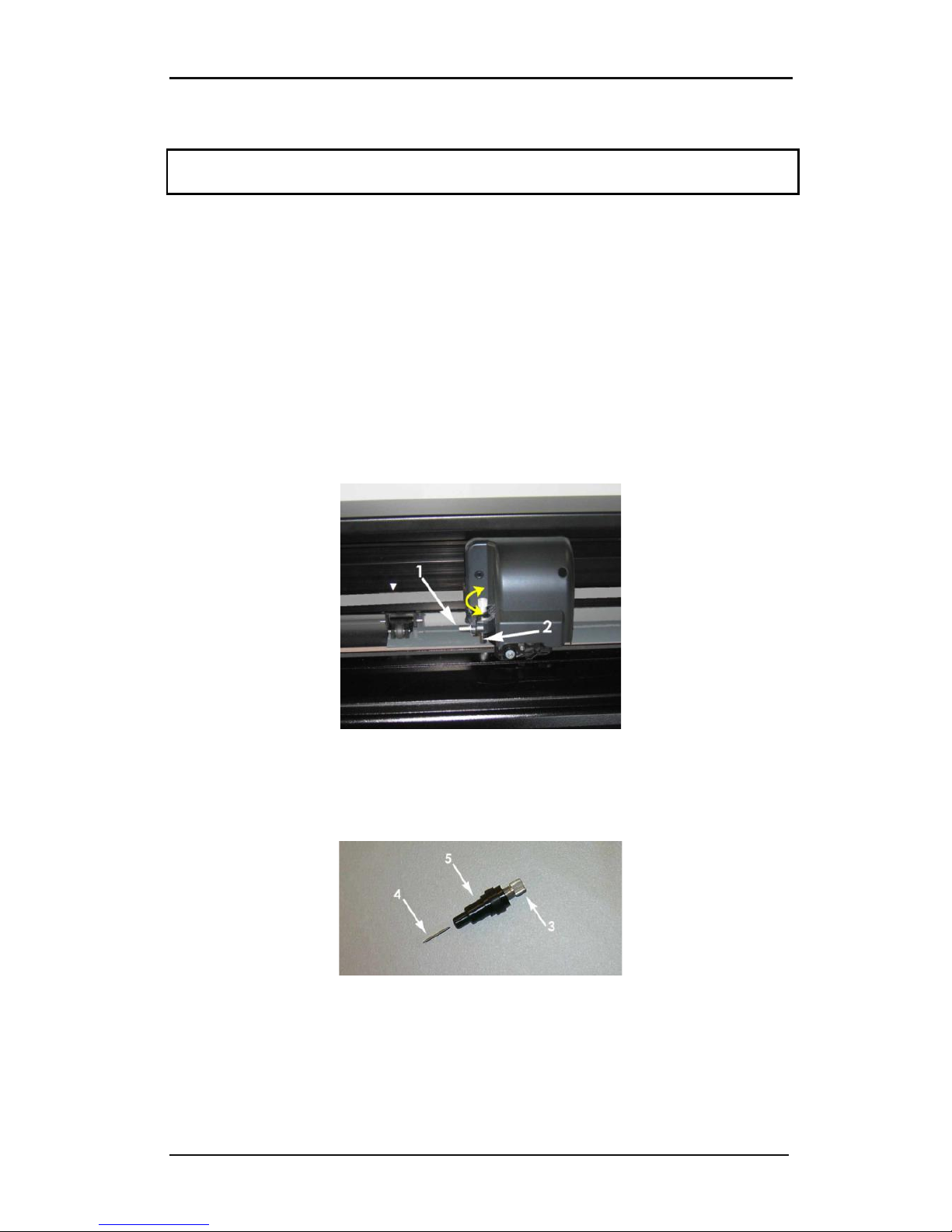
S CLASS™ cutter User’s Manual
Setup 1-36
1.6 Tool Installation
SAFETY WARNING: The S CLASS™ cutters use razor-sharp knives. To avoid serious injury, use
caution when installing, removing or otherwise handling the knife!
1.6.1 Cutters with drag head
1.6.1.1 Knife installation
A knife has been pre-installed in the cutter.
For safety reasons, the knife depth has been set to zero. Simply turn out the knife (see FIG
1-24 yellow arrow clockwise) to start cutting. Below is the complete description of the knife
removal and knife installation.
Removing the drag knife
1. Loosen the head clamp screw (1), swing the clamp arm back and remove the knife
holder from the clamp (2).
FIG 1-26
1-26 REMOVING THE DRAG KNIFE HOLDER FROM THE CLAMP
2. Turn the knurled adjustment knob (3) clockwise to push the knife (4) out of the holder
(5).
FIG 1-27
1-27 REMOVING THE KNIFE FROM THE STANDARD DRAG KNIFE HOLDER
3. Carefully pull the knife from the holder.
Page 48
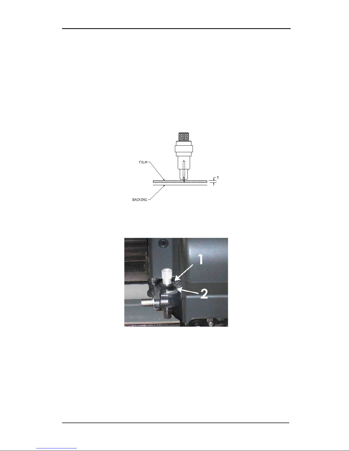
S CLASS™ cutter User’s Manual
Setup 1-37
Installing the drag knife
1. Remove the aluminum plunger from the plastic knife holder (5) by turning the knurled
adjustment knob (3) counterclockwise until the plunger comes out of the holder.
2. Insert the conical, non-cutting end of the knife into the opening in the narrow end of
the holder; gently push the knife all the way in.
3. Turn the holder upside down and tap it lightly on a solid surface to ensure that the knife
is completely inserted.
4. Slowly turn the knurled knob clockwise until the tip of the blade extends the distance
required for the desired cutting media (t) as shown in figure below.
FIG 1-28
1-28 KNIFE LENGTH ADJUSTMENT
5. Insert the knife holder into the rear (1) of the dual head clamp, seating it firmly.
FIG 1-29
1-29 DUAL CLAMP DRAG HEAD
6. Close the clamp and tighten the clamp screw.
1 is the position for knife and pen.
2 is the position for a pouncing tool (see section 1.6.1.3).
Page 49
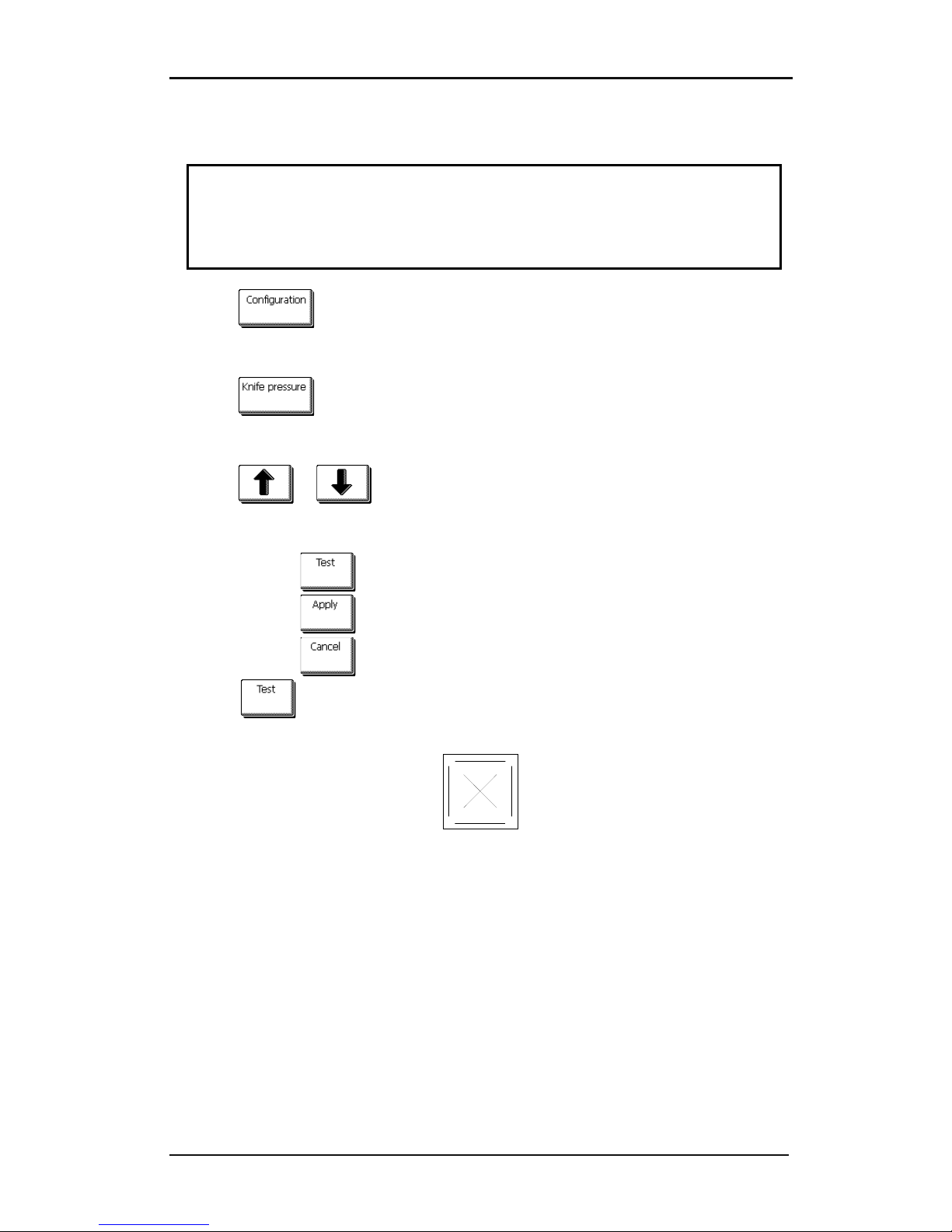
S CLASS™ cutter User’s Manual
Setup 1-38
Setting knife depth and pressure:
(media must be loaded in the cutter before knife pressure can be tested).
WARNING
Each keystroke can initiate an internal test or movement of head or media.
Keep fingers and other body parts away from the cutting area.
There are hazardous moving parts.
1. Press .
A new screen will appear showing the most common menu items (see section 2.1).
2. Press .
Current knife pressure will appear on screen.
3. Press or to change the knife pressure.
The new value (in bold) will change
1. Press to perform the internal knife pressure test.
2. Press to confirm the chosen knife pressure and exit the menu.
3. Press to leave the pressure unchanged.
Once is pressed, the current knife pressure value will be set automatically to
the new value and the cutter will cut the knife pressure test pattern.
FIG 1-30
1-30 KNIFE PRESSURE TEST PATTERN
Peel out the rectangle and inspect the media backing.
The knife depth is set correctly when the test pattern cuts through the vinyl completely, the
vinyl is removed, and the blade tip visibly scratched the front side of the media backing. The
blade should never cut through the backing; just slightly scratch the silicon coating and first
few fibers of the backing material.
Because the knife pressure setting depends on the thickness and type of media to be cut,
adjusting knife pressure will require some practice. In general, the knife depth must be
increased when using thicker types of vinyl and decreased when using thinner types of
vinyl.
Page 50

S CLASS™ cutter User’s Manual
Setup 1-39
CAUTION: After setting the cutting depth and/or the knife pressure, perform a thorough
visual check of the knife blade, which can be seen protruding from the knife holder, and
test cutting results on a scrap of vinyl media.
WARNING: Do not operate the cutter if the knife blade cuts through the media backing, as
this will seriously damage the cutter's rubber cutting strip and the knife.
CAUTION: For most vinyl cutting operations, the knife blade tip will be barely visible at the
bottom of the knife tool. If the knife blade tip is clearly visible, then the cutting depth must
be readjusted.
To prevent damage to the cutter, check the depth of the knife blade tip and the quality of
the cut each time you load a different type of vinyl into the cutter.
Page 51

S CLASS™ cutter User’s Manual
Setup 1-40
1.6.1.2 Pen installation
The S CLASS™ drag cutters can also be operated with a plotter-type pen. After replacing the
knife with a pen, the cutter can be used as a plotter to draw draft plots of new or existing
designs on paper.
1. Loosen the head clamp screw and swing the clamp arm back, then remove the tool
from the clamp.
2. Install the pen in the rear slot, close clamp arm, and tighten the clamp screw.
3. The change of tool can either be input on the touch panel with Summa Cutter Control
(PC only), or with the cutting software.
Selecting pen operation disables the knife offset correction, and changes the pressure to
“pen pressure.”
NOTE: The information on the touch panel shows the tool currently selected by the cutter.
Make sure the cutter’s tool setting matches the actual tool in use.
1.6.1.3 Pouncing pin installation
The S CLASS™ drag cutters can also be operated with a pouncing tool. After replacing the
knife with a pouncing tool, the cutter can be used as a paper pouncer.
1. Loosen the head clamp screw and swing the clamp arm back, then remove the tool
from the clamp.
2. Install the pouncing tool in the front slot, close clamp arm, and tighten the clamp screw.
3. The change of tool can either be input on the touch panel with Summa Cutter Control,
or with the cutting software.
Selecting pouncing tool operation disables the knife offset correction, changes the pressure
to “pouncing pressure” and will add “pouncing gap” to the tool properties.
NOTE: The information on the touch panel shows the tool currently selected by the cutter.
Make sure the cutter’s tool setting matches the actual tool in use.
CAUTION: Before starting to pounce, check whether the pouncing tool is positioned above
the black pouncing strip. If the pouncing tool is mounted in the rear slot of the clamp, the
cutting strip will be irreversibly damaged.
Page 52
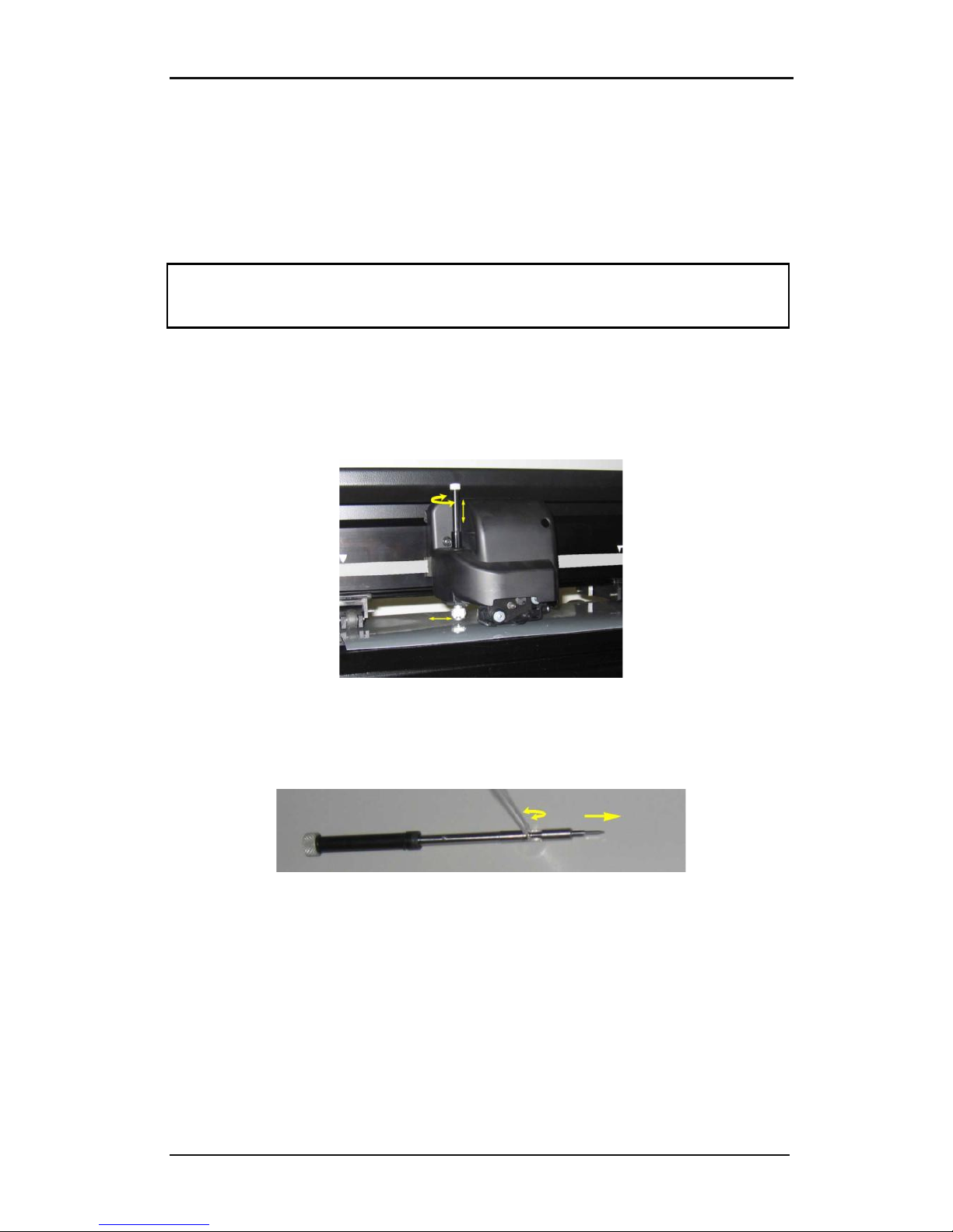
S CLASS™ cutter User’s Manual
Setup 1-41
1.6.2 Cutters with tangential head
1.6.2.1 Tangential knife installation
A knife has been pre-installed in your cutter. For safety reasons, the knife depth has been
set to zero. Simply turn out the knife (see fig FIG 1-31) to start cutting. Below is the complete
description of how to remove or install a knife.
NOTE: To benefit fully from the advantages of the tangential knife, the amount the knife
extends is very important. The knife pressure may not control the knife depth; the two
rollers of the nosepiece should always touch the media, thus controlling the knife depth.
Removing the tangential knife
1. Turn the knife holder counterclockwise. The holder will rise up, eventually making it
possible to lift the knife holder out of the tangential head. Underneath is the nosepiece.
Remove this part if another tool will be used in the cutter.
FIG 1-31
1-31 REMOVING THE TANGENTIAL KNIFE HOLDER
2. The knife can be removed from the knife holder by using something like a flat
screwdriver to pry between the knife and the knife holder in the groove.
FIG 1-32
1-32 REMOVING KNIFE FROM THE TANGENTIAL KNIFE HOLDER
Page 53
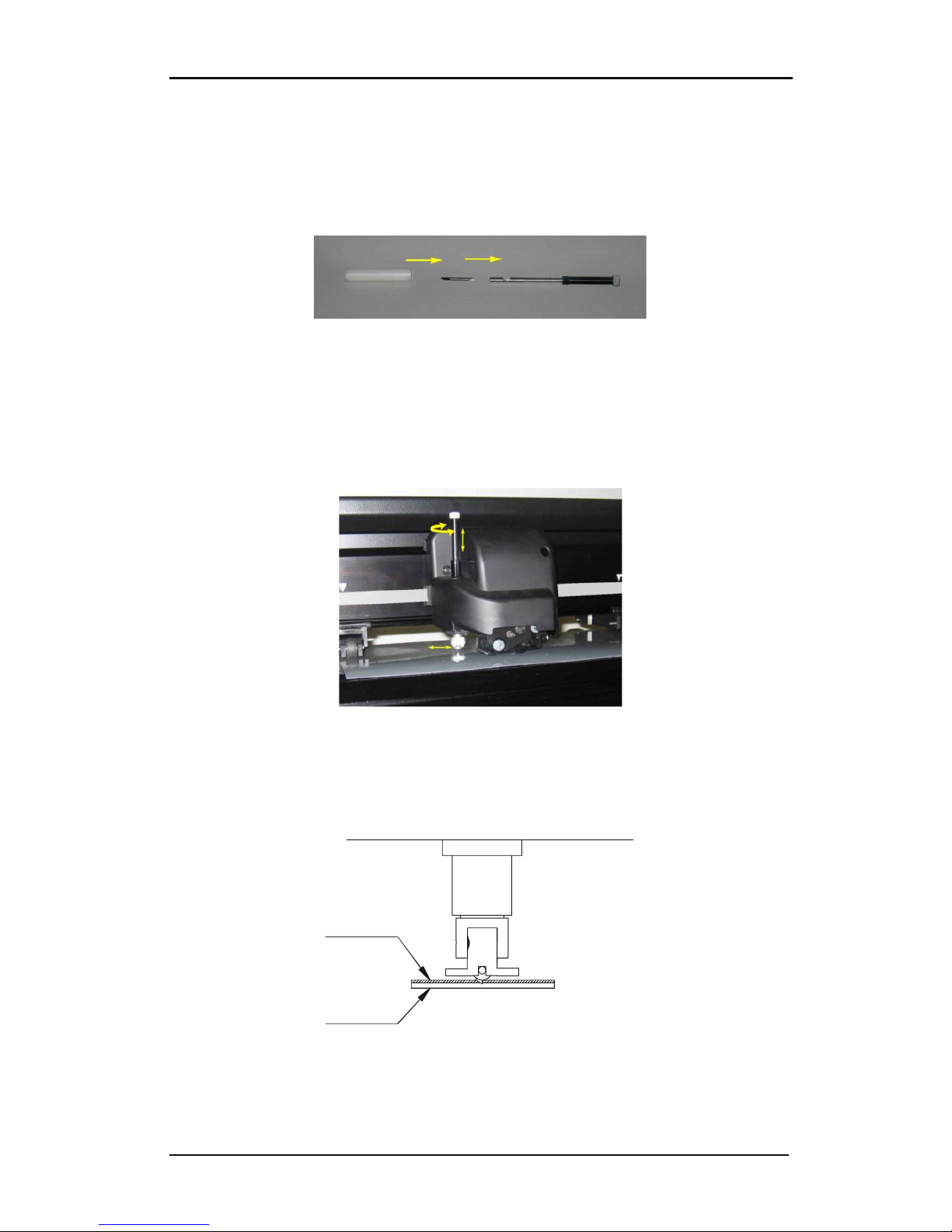
S CLASS™ cutter User’s Manual
Setup 1-42
Installing the tangential knife and setting knife depth
1. Insert the standard knife blade into the knife holder. Make sure the knife blade is firmly
fixed in the holder. The knife is inserted correctly if it cannot be removed manually from
the knife holder. The installation tool can be used to apply enough pressure on the knife
to secure it.
FIG 1-33
1-33 BLADE ASSEMBLY
2. Insert the nosepiece from the side until it snaps into place. Gently insert the knife into
the tool shaft. Hold the nosepiece in place with one hand and, with the other hand, turn
the knife holder counterclockwise until the alignment pin fits into the small notch of the
tool shaft. Now turn the knife holder clockwise until its thread takes hold inside the tool
shaft.
FIG 1-34
1-34 INSERTING THE TANGENTIAL KNIFE HOLDER
3. Holding the nosepiece in place with one hand, adjust the knife depth with the other
hand by turning the knife holder clockwise until the knife tip is just visible from under
the nosepiece.
Film
Backing
FIG 1-35
1-35 KNIFE DEPTH ADJUSTMENT
Page 54
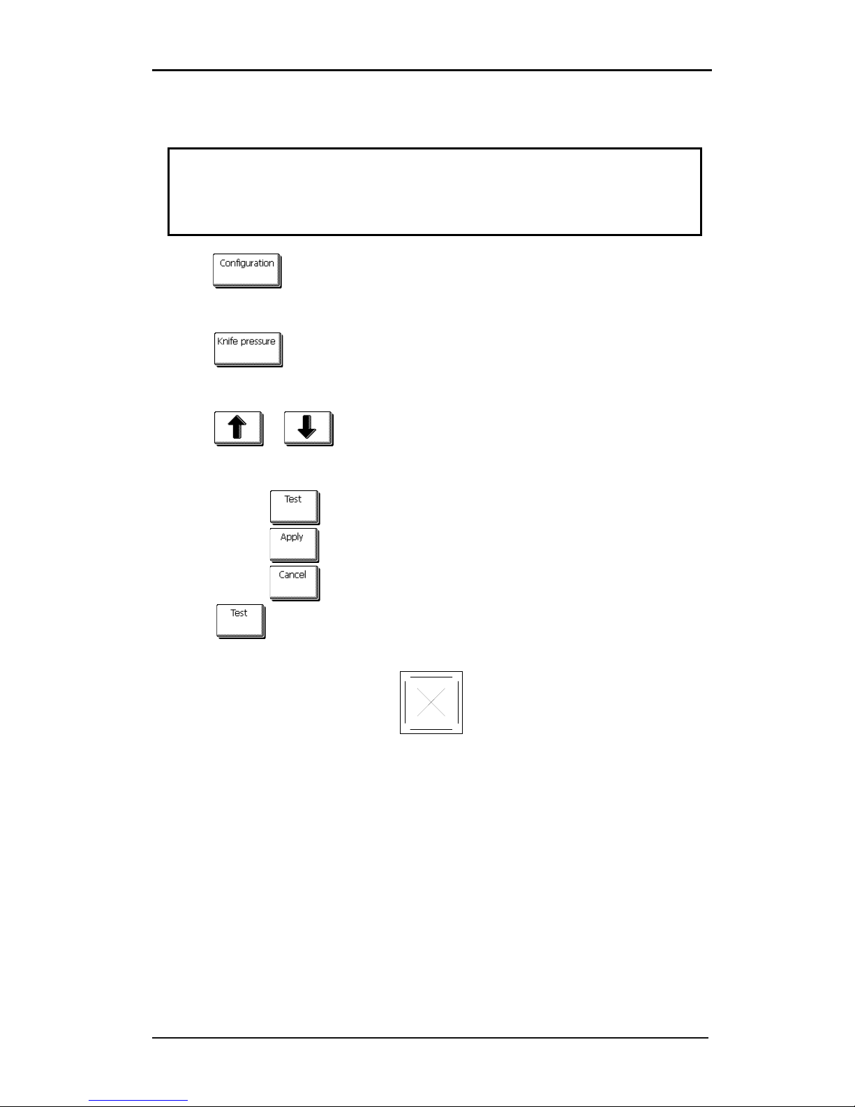
S CLASS™ cutter User’s Manual
Setup 1-43
Setting pressure and checking knife depth:
(media must be loaded in the cutter before knife pressure can be tested).
WARNING
Each keystroke can initiate an internal test or movement of head or media.
Keep fingers and other body parts away from the cutting area.
There are hazardous moving parts.
1. Press
.
A new screen will appear showing the most common menu items (see section 2.1).
2. Press .
Current knife pressure will appear on screen
3. Press or to change the knife pressure.
The new value (in bold) will change
1. Press to perform the internal knife pressure test.
2. Press to confirm and exit the knife pressure menu.
3. Press to leave the pressure unchanged.
4. Once is pressed, the current knife pressure value will be set automatically to
the new value and the cutter will cut the knife pressure test pattern.
FIG 1-36
1-36 KNIFE PRESSURE TEST PATTERN
Peel out the rectangle and inspect the backing.
The knife depth is set correctly when the test pattern cuts through the vinyl completely, the
vinyl is removed, and the blade tip visibly scratched the front side of the media backing. The
blade should never cut through the backing; just slightly scratch the silicon coating and first
few fibers of the backing material.
Page 55

S CLASS™ cutter User’s Manual
Setup 1-44
NOTE: The knife pressure can also be used to check the knife depth (which is controlled by
the amount the knife extends outs of the nosepiece). If the correct knife pressure is raised
by 150 gr, then the knife may not cut through the backing of the vinyl. If it does, then the
knife depth needs to be reduced.
CAUTION: After setting the cutting depth and/or the knife pressure, perform a thorough
visual check of the knife blade, which can be seen protruding from the knife holder, and
test cutting results on a scrap of vinyl media.
WARNING: Do not operate the cutter if the knife blade cuts through the media backing, as
this will seriously damage the cutter's rubber cutting strip and the knife.
CAUTION: For most vinyl cutting operations, the knife blade tip will be barely visible at the
bottom of the knife tool. If the knife blade tip is clearly visible, then the knife depth must be
readjusted.
To prevent damage to the cutter, check the depth of the knife blade tip and the quality of
the cut each time you load a different type of vinyl into the cutter.
Page 56

S CLASS™ cutter User’s Manual
Setup 1-45
1.6.2.2 Pen installation
The S CLASS™ tangential cutters can also be operated with a ballpoint pen. After replacing
the knife with a pen, the cutter can be used as a plotter to draw draft plots of new or
existing designs on paper.
1. Turn the installed tool counterclockwise. The holder will raise up, making it possible to
lift the knife holder out of the tangential head. Underneath is the place for a nosepiece.
Remove this part also if it is mounted.
2. Insert the ballpoint pen holder into the tool shaft.
3. Gently insert the ballpoint pen into the tool shaft. Turn the ballpoint pen clockwise all
the way down.
4. The change of tool can either be input on the touch screen with Summa Cutter Control,
or with the cutting software.
Selecting pen operation changes the pressure to “pen pressure.”
NOTE: The information on the touch panel shows the tool currently selected by the cutter.
Make sure the cutter’s tool setting matches the actual tool in use.
1.6.2.3 Pouncing pin installation
The S CLASS™ tangential cutters can also be operated with a pouncing tool. After replacing
the knife with a pouncing tool, the cutter can be used as a pouncer.
1. Turn the installed tool counterclockwise. The holder will rise up, making it possible to
lift the tool out of the tangential head. Underneath is the place for a nosepiece. Remove
this part also if it is mounted.
2. Remove the black plug from the front tool shaft.
3. Gently insert the pouncer into the front tool shaft. Turn the pouncer clockwise all the
way down.
4. The change of tool can either be input on the touch screen with Summa Cutter Control,
or with the cutting software.
Selecting pouncer operation changes the pressure to “pouncer pressure” and adds
“pouncing gap” to tool properties.
NOTE: The information on the touch panel shows the tool currently selected by the cutter.
Make sure the cutter’s tool setting matches the actual tool in use.
CAUTION: Before starting to pounce, check whether the pouncing tool is above the black
pouncing strip. If the pouncer is mounted in the rear slot of the clamp, the cutting strip will
be irreversibly damaged.
Page 57
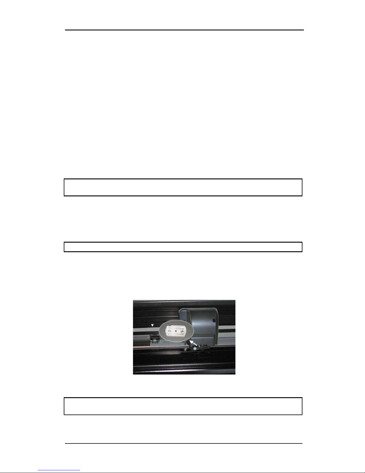
S CLASS™ cutter User’s Manual
Setup 1-46
1.6.2.4 Drag knife installation
The S CLASS™ tangential cutters can also be operated with a drag knife. To set the
properties for the drag knife, see section 1.6.1.1. Follow steps 1 through 4, and then
continue with step 5 as follows:
1. Turn the installed tool counterclockwise. The holder will rise up, making it possible to
lift the knife holder out of the tangential head. Underneath is the place for a nosepiece.
Remove this part also if it is mounted.
2. Mount the nosepiece for the drag knife.
3. Gently insert the drag knife into the rear tool shaft. Turn the drag knife clockwise all the
way down.
4. The change of tool can either be input on the touch screen with Summa Cutter Control,
or with the cutting software.
5. Selecting drag knife operation will add “knife offset” to tool properties.
NOTE: The information on the touch panel shows the tool currently selected by the cutter.
Make sure the cutter’s tool setting matches the actual tool in use.
1.6.3 Replacement of the separation knife blade
The tool carriage also holds the separation knife. With this knife (razor blade), the job can be
automatically cut off after it is finished.
NOTE: This separation knife may only be used with standard vinyl (max 0.25mm thick).
1. Remove the razor blade holder by turning on the knurled screw at the bottom of the
tool carriage.
2. The razor blade is kept in its place by a small magnet. Turn it around or replace it when
it is worn down, figure 1-b.
FIG 1-35
1-37 RAZOR BLADE FOR AUTOMATIC SEPARATION OF MEDIA
NOTE: The assembly is tilted under an angle of +/- 30° when it is put back on the machine.
Mind the position of the assembly before replacing the razor blade.
Page 58
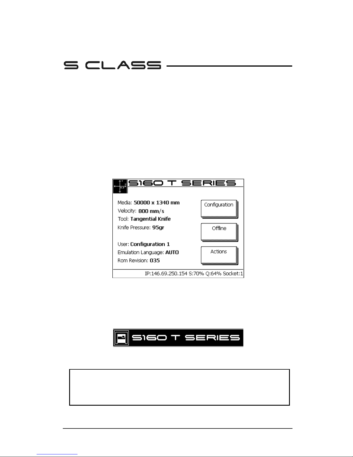
Basic Operation 2-1
2 Basic Operation
2.1 Touch Screen
The 320x240-dot touch screen provides a unique interface system that provides detailed
cutter status information and offers a more flexible and powerful control of the cutter’s
configuration.
All screen and optional panel controls on the touch screen are easily formatted to allow
quick access to the most common cutter settings.
Next to the status messages and/or menu options displayed on the touch screen, you will
see button symbols that can be pressed to change menu items or to change the value for a
given submenu/parameter.
FIG 2-1
2-1 TOUCH SCREEN
There is also screen saving feature. After a certain amount of time the screen goes blank and
the model type of cutter appears and disappears in the middle of the touch screen.
Touching the screen once disables the screen saver.
FIG 2-2
2-2 SCREEN SAVER
WARNING
Each keystroke can initiate an internal test or movement of head or media.
Keep fingers and other body parts away from the cutting area.
There are hazardous moving parts.
Page 59
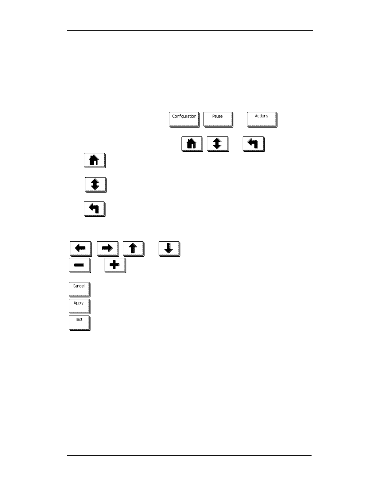
S CLASS™ cutter User’s Manual
Basic Operation 2-2
2.1.1 Touch screen
The touch screen provides information and lets the user change the cutter’s parameters.
Most common buttons on touch screen:
Normally, the status or current value is visible on the left side of the screen, while the
control buttons appear on the right side.
There are three main control buttons: ,
and .
If a menu is entered, 3 navigation buttons: , and may appear.
Press to return to the status screen. If media is loaded in the cutter, then the cutter
will come online and be ready to cut a job sent from the computer.
Press for more menu options. If there are more than 6 options for the chosen
menu, then pressing this button will reveal the rest of the options onscreen.
Press to return one step in the menu structure.
Other buttons that will appear on the screen are:
, , and arrow buttons to move tool carriage or media or
and to change the values of parameters.
to cancel an instruction or change in parameter.
to apply a change in parameter.
to initiate an internal test.
Bottom line:
The bottom line gives extra information on the way the cutter can be conected to the
computer.
If a wireless board is installed, then information about the setting is shown (IP address,
signal strength, signal quality and if connected or not).
In other cases, the current USB class is shown.
Page 60

S CLASS™ cutter User’s Manual
Basic Operation 2-3
2.1.2 Configuration
The Configuration button gives access to the main menu. Pressing this button will cause the
cutter to go offline and suspend all operations in progress. The main menu contains all
submenus and access to tests and calibration routines.
The chosen tool will influence the configuration displayed.
Settings: This menu offers access to different submenus that allow configuration of the
cutter’s operating parameters. Access to some of the submenus will be determined by
plotting language or tool type.
Tests & Setup: This menu offers access to the different internal tests and calibration
routines. The calibration routines are used to adjust and fine-tune the cutter for the chosen
application. The internal tests are used for diagnostics.
Knife (pen or pounce) pressure: This menu allows users to set or modify the cutting
pressure of the current tool.
Knife offset: This menu allows users to set or modify the distance between the tip of the
knife and the axis. The default knife offset value is .45 mm. Knife offset is only displayed
when the chosen tool is a drag knife.
Pouncing gap: The pouncing gap parameter is used to set or modify the distance
between the pounced holes. Pouncing gap only applies when the machine is in “pounce”
mode.
Velocity: The velocity is used to set or modify the velocity of the tool.
User Selection: The S CLASS™ cutters include 8 user configurations, all of which consist of
the same parameters. Each configuration can have unique parameter settings. This allows
the cutter to be quickly and easily reconfigured for different types of jobs or media. The
touch screen can be used to change the user. However, user configuration names can only
be modified through Summa Cutter Control.
Page 61
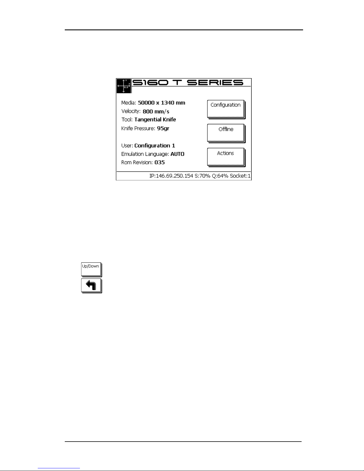
S CLASS™ cutter User’s Manual
Basic Operation 2-4
2.1.3 Online/Pause
Online and pause are two important concepts when using the S CLASS™ cutters. The cutter
is online only when the status of the touch screen is similar to figure 2-2.
FIG 2-3
2-3 ONLINE STATUS SCREEN
When online, the cutter can be addressed by the host computer, which means that the
cutter will execute cutting or plotting instructions issued by the host computer's application
software. As soon as any other button on the cutter is pressed, the cutter pauses and can no
longer be addressed by the host computer. However if the computer was busy sending
cutting data to the cutter it will be able to do so until the buffer of the cutter is full.
If the pause button is pressed, then the tool can be moved around the working area with
arrow buttons.
Press
to raise or lower the tool (once push toggles the status each time).
Press to set the cutter online again.
2.1.4 Actions
The “Actions” button is used to move the origin (start point for cutting), initiate a load
sequence, abort the cut in progress, or recut the last file.
When the action button is pressed during a job, then the job will halt immidiatelly
The “Set origin” instruction is used to move the knife origin.
The “Load” instruction is used to initiate a load sequence.
The “Reset” instruction performs a complete reset of the cutter.
The “Media alignment” instruction is used to initiate registration of the OPOS markers
just before a contour cut is begun.
The “Recut” instruction recuts the last file sent to the cutter (provided that it fits in the
cutter’s memory (buffer).
The “Cut off” instruction is used to cut of a job done and to reset media origin.
Page 62
S CLASS™ cutter User’s Manual
Basic Operation 2-5
2.2 How to Set Tool Parameters
The S CLASS™ cutters can work with a knife, pen or pouncer. With the T version there is the
choice between drag knife and tangential knife.
Once a tool has been changed, then the tool parameters (menu settings) must be reset or
checked.
All the different tools have one parameter name in common: the pressure.
Each tool has also its specific parameters.
Tool parameters can be changed by either changing them in the current user, or simply by
changing user (see section 2.4).
NOTE: The S CLASS™ cutters will only perform according to specifications if a genuine
Summa knife, pen or pouncing tool is installed. Do not replace the standard knife, pen or
pouncing tool with products from other manufacturers.
Each keystroke can initiate an internal test or movement of head or media.
WARNING
KEEP FINGERS AND OTHER BODY PARTS AWAY FROM THE CUTTING AREA. THERE ARE
HAZARDOUS MOVING PARTS.
2.2.1 Setting tool type
1. Power on the cutter.
2. Press .
The main menu will appear on the screen.
3. Press .
The different configuration menus will appear on screen.
4. Press .
A list of possible tools will be shown.
5. Use or to change the tool.
6. Press to select the tool that is highlighted on screen.
Page 63
S CLASS™ cutter User’s Manual
Basic Operation 2-6
2.2.2 Changing tool pressure
1. Power on the cutter, load media, and mount tool (see section 1).
2. Press .
The main menu will appear on the screen. Buttons may vary according to the chosen tool
type. However, there will always be a button labeled with the word ‘pressure.’
3. Press button.
The current tool pressure will appear on screen.
4. Use or to change the pressure.
The new value (in bold) will change.
1. Press to perform the internal tool pressure test (see 1.6.1.1).
2. Press to confirm and exit the tool pressure menu.
3. Press to leave the pressure unchanged.
2.2.3 Changing drag knife offset
A very important parameter for a drag knife is the offset. The offset is the distance between
the knife center and the knife tip.
NOTE: Knife offset should be set each time the knife is changed and should be checked if
the knife shows signs of wear.
Typical knife offset for Summa knives is between 0.41 and 0.45 for standard knives, and
between 0.9 and 0.97 for sandblast knives.
NOTE: Sandblast knives should be used when the material that needs to be cut is thicker
than 0.25mm.
Changing knife offset:
1. Power on the cutter, load media, and mount drag knife (see section 1).
2. Press .
The main menu will appear on the screen.
3. Press .
The current knife offset will appear on screen.
Page 64
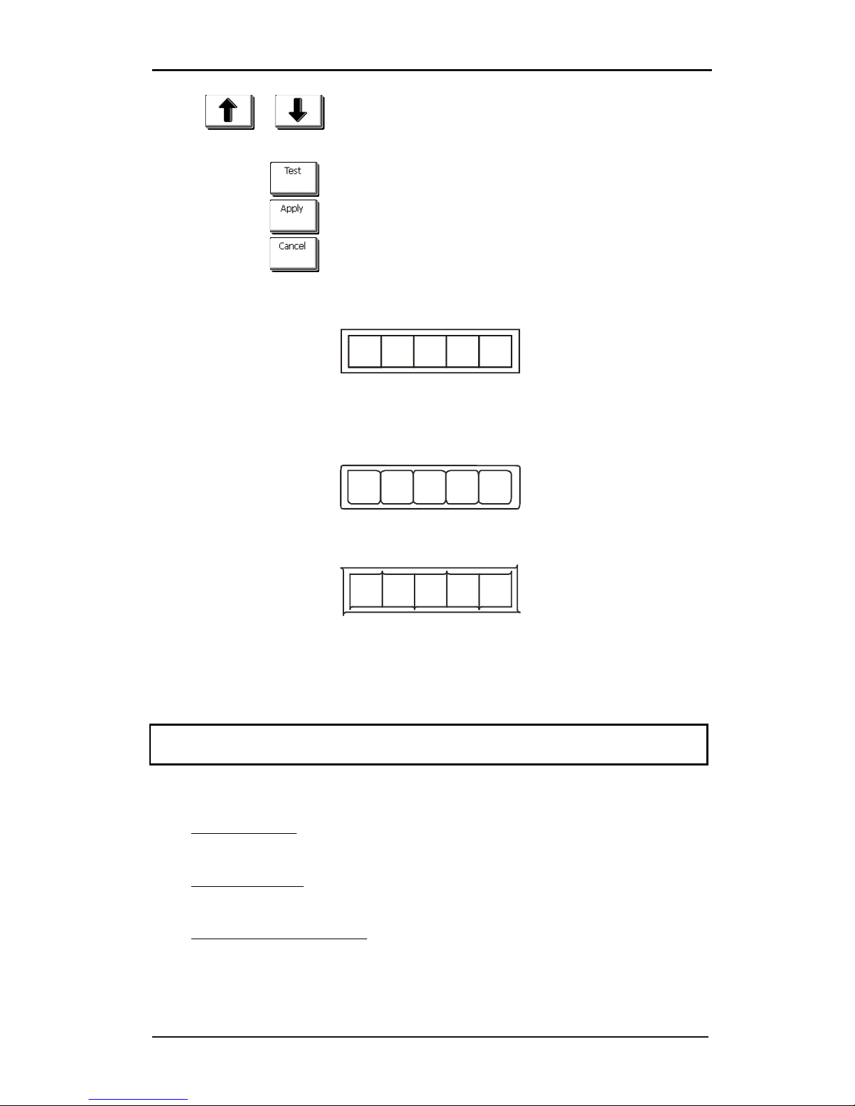
S CLASS™ cutter User’s Manual
Basic Operation 2-7
4. Use or to change the knife offset.
The new value (in bold) will change.
1. Press to perform the internal knife offset test.
2. Press to confirm and exit the knife offset menu.
3. Press to leave the knife offset unchanged.
When the knife offset is set correctly, the test pattern looks like this:
FIG 2-4
2-4 CORRECT KNIFE OFFSET PATTERN
When the knife offset is too low, the test pattern looks like this:
When the knife offset is too high, the test pattern looks like this:
2.2.4 Calibrating a tangential knife
The purpose of the knife calibration routine is to detect and, if necessary, to correct
problems related to the concentricity of the tangential knife blade.
NOTE: Knife calibration should be done each time the knife is changed and should be
checked if the knife shows signs of wear.
Knife calibration errors may be due to any of the following causes:
• Origin deviation. The knife tip is slightly rotated in relation to its theoretical 0° angle.
This error can be corrected by adjusting the origin.
• Lateral deviation. The knife tip deviates from its theoretical center in the lateral
direction. This error can be corrected by adjusting the lateral parameter.
• Longitudinal misalignment. The knife tip deviates from its theoretical center in the
longitudinal direction. This error can be corrected by adjusting the longitudinal
parameter.
Page 65
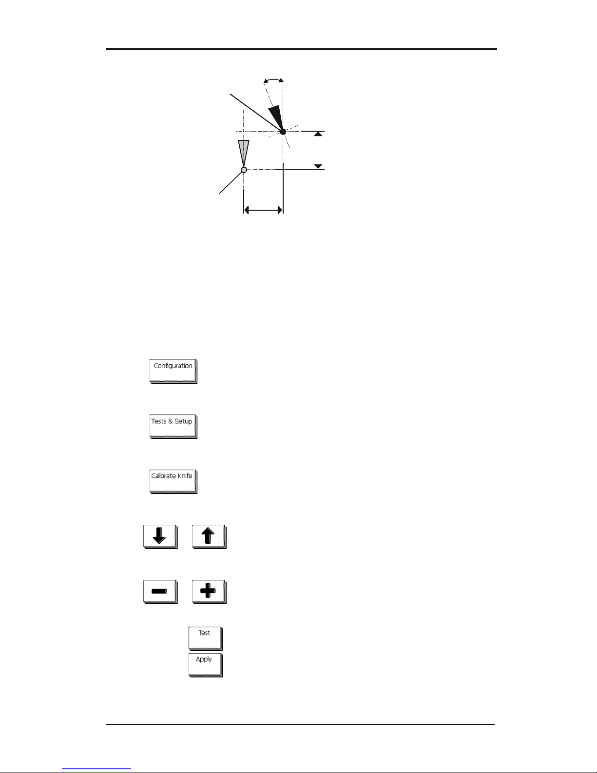
S CLASS™ cutter User’s Manual
Basic Operation 2-8
LONGITUDINAL deviation
LA TER AL deviation
Theoretical center
of the knife
ORIGIN deviation
Real center
of the knife
FIG 2-5
2-5 POSSIBLE KNIFE CALIBRATIONS
During the knife calibration routine, the cutter will cut a series of test patterns that allow the
user to identify errors in knife rotation and concentricity. Use the touch screen to make
corrections.
Setting tangential knife parameters:
1. Power on the cutter, load media, and mount tangential knife (see section 1).
2. Press .
The main menu will appear on the screen.
3. Press .
The main test will appear on screen.
4. Press .
The three knife parameters will appear on screen.
5. Use or to select the parameter to be changed.
The selected parameter will be highlighted on the touch screen.
6. Use or to change the parameter.
The value (inverse) will change.
1. Press to perform the internal knife calibration test.
2. Press to confirm and exit the knife calibration menu.
Page 66
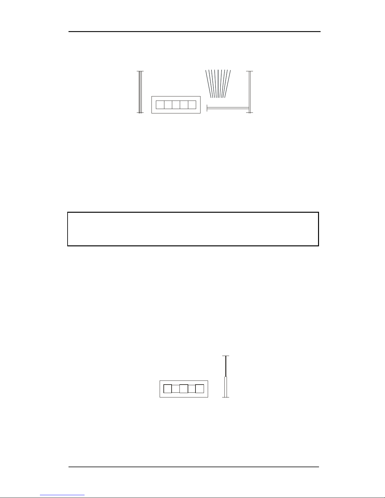
S CLASS™ cutter User’s Manual
Basic Operation 2-9
When the knife offset is set correctly, the test pattern looks like this:
FIG 2-6
2-6 CORRECT TANGENTIAL KNIFE CALIBRATION TEST
Rectangle 1 and 2 should weed out (remove) smoothly without sticking to the rest of the
vinyl.
The fan shaped pattern 3 should have a clear cut line in the middle; the ones at the sides
show burs.
The squares in 4 should be aligned and equal in size.
The 4 vertical cuts in 5 should be clear without any burs and straight all the way from top
to bottom (not rounded near the horizontal lines).
NOTE: It is possible that not all test patterns come out perfect (depends on the type of
vinyl). Test pattern 1 and 4 are the most important test patterns. They should be as close to
perfect as possible.
Start with the setting of the origin, then set the other parameters
Origin correction
If the clear cut line in test pattern 3 is to the right, then increase the value of the origin,
begin in steps of 20, and lower the steps when nearing the correct origin setting.
It helps sometimes to gently feel the pattern to find out which side has the clear-cut line.
If the clear cut line in test pattern 3 is to the left, then decrease the value of the origin,
begin in steps of 20, and lower the steps when nearing the correct origin setting.
Lateral correction
Weed out (remove) the rectangle in pattern 1 and in pattern 4, if the test pattern is like
the one below, decrease the value of the lateral parameter to correct the closing lines
cut.
1
2
3
4
5
Page 67
S CLASS™ cutter User’s Manual
Basic Operation 2-10
However, if the test cut resembles the pattern below, increase the value of the lateral
parameter to correct the closing lines cut.
Longitudinal correction
Weed (remove) out the rectangle and, if you obtained a pattern like the one below,
decrease the value of the longitudinal parameter to correct the closing lines cut.
However, if the test cut resembles the pattern below, increase the value of the
longitudinal parameter to correct the closing lines cut.
Each time a parameter is changed, press to perform the internal knife calibration
test.
NOTE: Failing to set the knife parameters correctly will result in poor cut quality.
Page 68
S CLASS™ cutter User’s Manual
Basic Operation 2-11
2.3 How to Set Cutting Speed
The actual speed at which the tool moves is determined by 4 different parameters. Speed
(and acceleration) while the tool is down; speed (and acceleration) while tool is up.
These 4 parameters have been bundled in one parameter to make changing speed fast and
easy.
This overall parameter is called “velocity” and is the speed the cutter uses when the tool is
down. If velocity is raised or lowered, then the other parameters are also raised or lowered
accordingly.
There is one fixed speed: the speed at which the cutter pulls the media from the roll. This
speed is fixed at 200mm/s (8ips).
Setting the cutting speed:
1. Power on the cutter.
2. Press .
The main menu will appear on the screen.
3. Press .
The velocity will appear on screen.
4. Use or to change the velocity.
The value (inverse) will change.
5. Press to confirm the new velocity.
6. Press to exit the menu without changing the velocity.
Setting the speed parameters separately:
1. Power on the cutter.
2. Press .
The main menu will appear on the screen.
3. Press .
The c
onfiguration menu will appear on screen.
Page 69
S CLASS™ cutter User’s Manual
Basic Operation 2-12
4. Press .
The 4 separate speed parameters will now appear on the screen.
NOTE: Velocity is the main speed parameter. The default value for the three other
parameters is AUTO. This means that they are linked to velocity (which is the speed when
the tool is down). These parameters can be set individually, but will then lose the link with
the velocity parameter.
5. Press , , or to select the parameter that
needs to be changed.
The chosen parameter will appear on screen.
6. Use or to change the value.
The value (inverse) will change.
7. Press to confirm the new value. Or Press to exit the menu without
changing the value.
NOTE:. Sometimes the cutter feeds the material too fast and the media has no time to
settle and fold into the basket. A fifth speed parameter is designed for such cases. The
speed of long X axis vectors is reduced automatically so that the media does not bulge.
8. Press .
The chosen parameter will appear on screen.
9. Use or to set to automatic or constant velocity.
The value (inverse) will change.
10. Press to confirm the new value. Or Press to exit the menu without
changing the value.
Page 70
S CLASS™ cutter User’s Manual
Basic Operation 2-13
2.4 How to Change the User (Quick Parameter Change)
The S CLASS™ cutters include 8 user configurations, all of which consist of the same
parameters. Each configuration can have unique parameter settings. This allows the cutter
to be quickly and easily reconfigured for different types of jobs or media.
NOTE: Factory default values for the different users are all set the same.
Changing the User Configuration:
1. Power on the cutter.
2. Press .
The main menu will appear on the screen.
3. Press .
The different users will appear on screen.
4. Use or to change user.
The user (inverse) will change.
5. Press to confirm the new user.
6. Press to exit the menu without changing the user.
TIP: Use easy names to quickly recognize what each user is configured to do.
Commonly used names are: Normal, Pen, Slow, Sandblast, Pouncer, Red intermediate vinyl,
etc.
NOTE: The touch screen can be used to change user configurations. User configuration
names can only be modified through Summa Cutter Control (PC only).
NOTE: There is a text file on the manual CD for the Mac users. The name of the file is
“name.enc”.
Edit the second line to change user name.
The second line in that file is: “SET USER01NAME Type_text_here.”.
First change in that line the number of the user’s name that needs to be changed.
Then change “Type_text_here” to the new name. Do not use spaces. Underscores will be
translated to spaces on the touch screen. Maximum length of a user name is 16 characters.
Do not change any other lines in this text file, then save it as text.
Finally send the file to the cutter.
Page 71
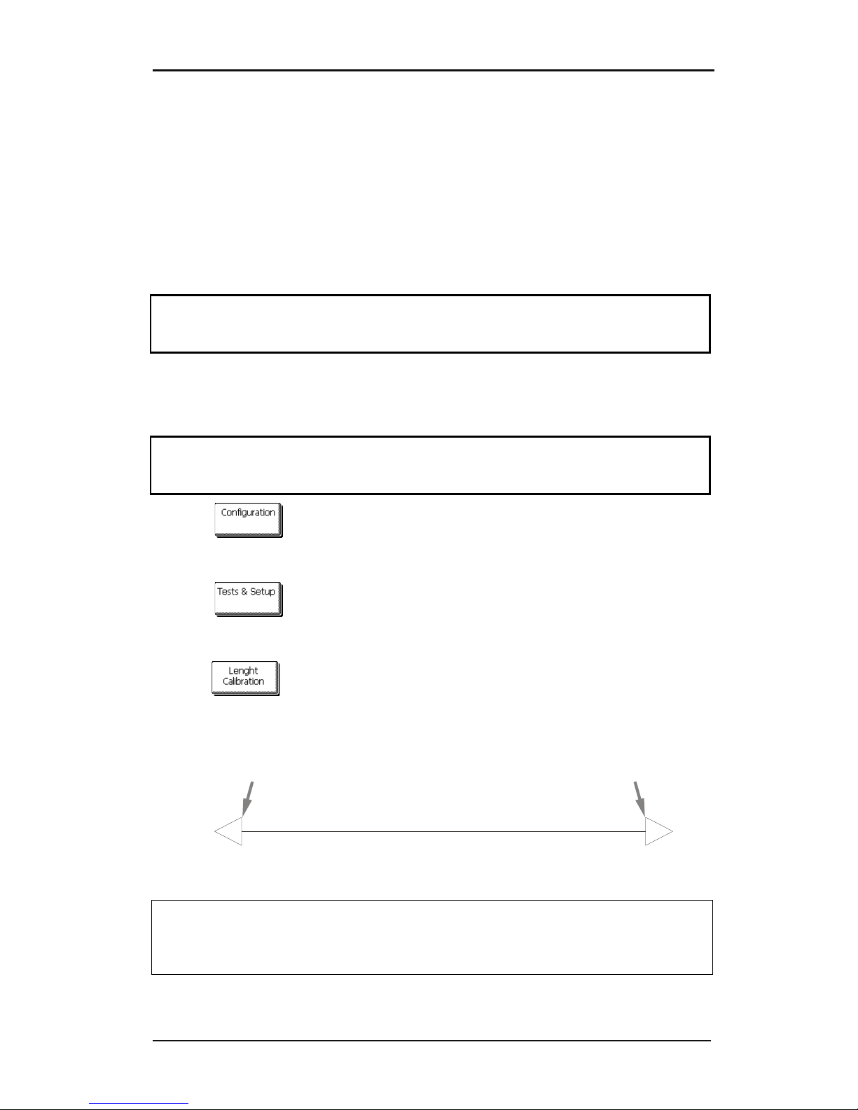
S CLASS™ cutter User’s Manual
Basic Operation 2-14
2.5 How to Make Sure the Sign Has the Correct Size
(Length Calibration)
The S CLASS™ cutters are friction-feed machines. This means that the cutting length is
dependent on the thickness of the material.
The cutters have been calibrated in the factory for standard 2-mil cast or 3-mil calendared
vinyl. Each user (the S CLASS™ has a total of 8) can hold a different calibration factor.
This is very helpful for multi-colored signs; it ensures that the parts in different colors match
up, even if different types of vinyl media are used.
NOTE: For standard use, it is not necessary to calibrate the machine. With standard vinyl
the accuracy is within 0.2%. However if high accuracy between different vinyl or colors is
needed, then calibration is necessary.
Calibrating the media (Length calibration):
1. Power on the cutter, load media, and mount knife (see section 1).
NOTE: The wider and longer the loaded media, the more accurate the calibration will be.
Use a piece of vinyl of maximum width and a length that is approximately 1.5 times the
width.
2. Press .
The main menu will appear on the screen.
3. Press
.
The different tests and calibration routines will appear on screen.
4. Press .
The cutter will reload the media and perform the length calibration test. Take out the media
and measure the length of the cut line with a ruler (measuring device). The length that has to
be entered is the distance between line 1 and line 2 as shown in the figure.
1 2
FIG 2-7
2-7 LENGTH CALIBRATION PATTERN
NOTE: The cutter will only be as accurate as the accuracy of the calibration. If the ruler
(measuring device) is inaccurate, then re-calibrating may make the cutter’s accuracy worse.
The accuracy of calibration will be directly reflected in the cuts. Set the cutter to Metric to
do the calibration. It is more accurate than the English unit system (see :Panel Units).
Page 72
S CLASS™ cutter User’s Manual
Basic Operation 2-15
5. Press to proceed with the calibration, press to stop.
6. Use or to change to the value of the measured length between the
two cut lines down the length of the vinyl roll.
7. Press to confirm the value of the measured length.
TIP: Once this user is calibrated, change the user name. This makes it easy for future
reference.
Page 73
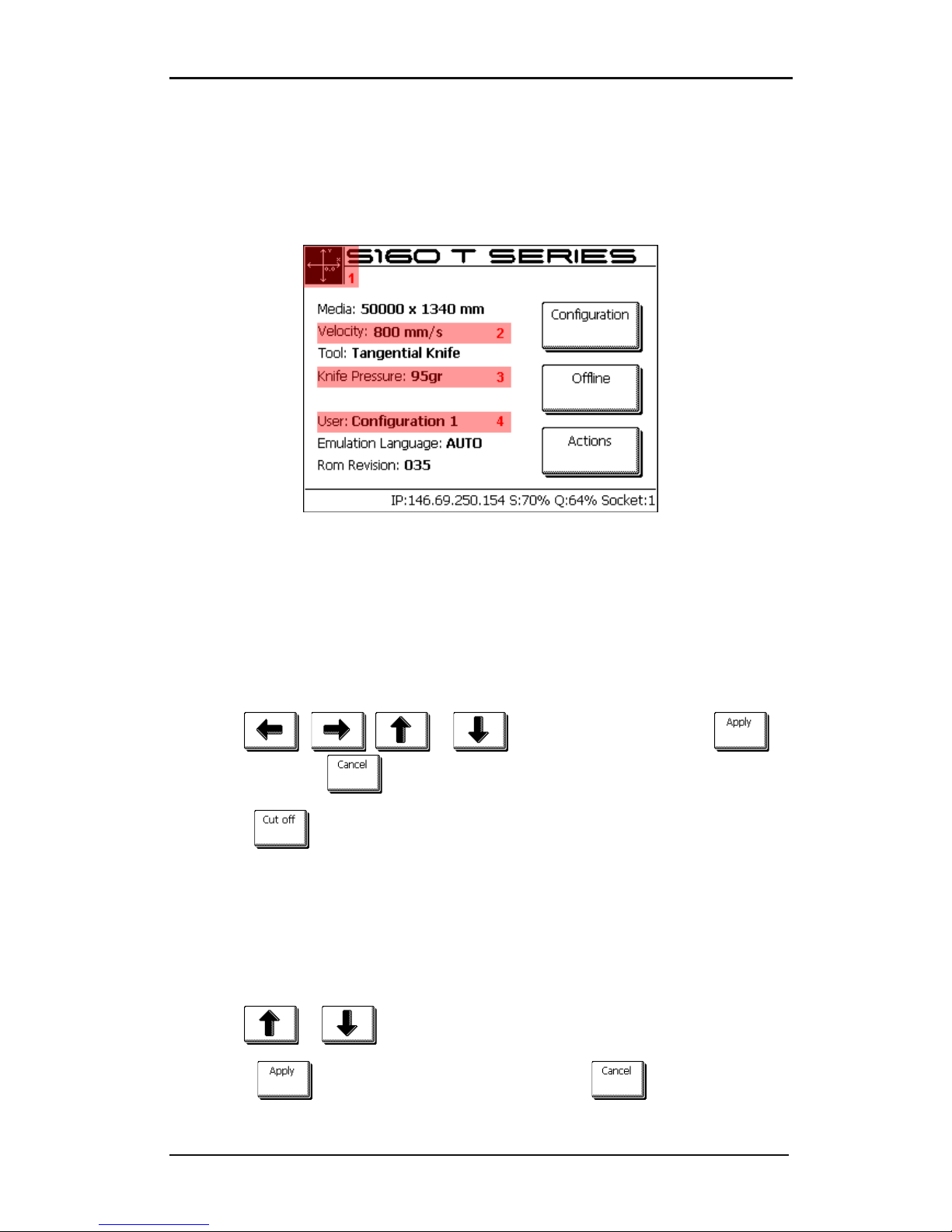
S CLASS™ cutter User’s Manual
Basic Operation 2-16
2.6 Touch screen shortcuts
There exist a couple of handy shortcuts when the cutter is online and waiting for the
computer to send a file. These shortcuts are not explicitly marked on the touch screen by a
button, but using the shortcuts have proved to be very helpful for quick actions. Below is a
picture showing the 4 areas for the shortcuts.
FIG 2-8
2-8 SHORTCUT AREAS IN START-UP SCREEN
Pressing these highlighted areas will guide the user directly to the parameter.
2.6.1 Changing origin
Press area 1
The origin menu will appear on screen
1. Use , , or to reposition the origin; press to
confirm or press to leave without changing the origin.
2. Press
to cut off a previous job if necessary; the cutter will then automatically
search the front of the media and set the new origin.
2.6.2 Changing velocity
Press area 2
The velocity menu will appear on screen, the current velocity is highlighted.
1. Use or to change the velocity.
2. Press to confirm the new velocity or press to leave the menu
without changing the velocity.
Page 74
S CLASS™ cutter User’s Manual
Basic Operation 2-17
2.6.3 Changing tool pressure
Press area 3
The pressure menu will appear on screen, the current pressure is highlighted.
1. Use or to change the pressure.
The new value (highlighted) will change.
2. Press to perform the internal tool pressure test (see 1.6.1.1).
3. Press to confirm and leave the tool pressure menu.
4. Press to leave the pressure unchanged.
2.6.4 Changing user
Press area 4
The different users will appear on screen.
1. Use or to change user.
2. Press to confirm the new user.
3. Press to leave the menu without changing the user.
Page 75
S CLASS™ cutter User’s Manual
Basic Operation 2-18
2.7 How to track difficult media
Some cutting media is not designed for use on a drum driven plotter. In most cases the
cause is a none rigid backing. A possible solution for this problem is using paneling. The
option paneling divides the whole job into panels in the media direction.
It then cuts out panel after panel making sure it does not have to transport the media back
and forth over long distances.
NOTE: Paneling has been developed in order to achieve better closing of figures on
material which is difficult to track accurately. It does NOT mean however that with paneling
these materials can be cut within the regular Summa specifications of tracking and
accuracy. Recommended panel sizes are between 5 – 10 cm
Setting the paneling parameters:
1. Power on the cutter.
2. Press .
The main menu will appear on the screen.
3. Press .
The advanced cutting menu will appear on screen.
4. Press .
The paneling menu will appear on screen.
5. Press .
The menu to activate or deactivate paneling will appear on screen.
6. Use or to set paneling to on.
On (inverse) will change.
7. Press to confirm.
The paneling menu will appear on screen.
8. Press .
Current panel size will appear on screen.
9. Use or to set paneling size.
New value will change.
10. Press to confirm.
Page 76

Basic Operation 3-1
3 OPOS (Optical POSitioning)
3.1 Introduction
Contour cutting is made possible by the S CLASS™’s highly accurate Optical Positioning
System (OPOS).
The OPOS sensor, which is mounted on the right-hand side of the tool carriage, registers
printed squares that are placed around the graphic. Because of this registration process,
OPOS can determine the exact position of the printed graphic.
The sensor drops automatically while registering the markers and rises again after
completing this task. The improved sensor can read virtually any kind of media-marker
combination.
3.2 Basic OPOS operation
Many versions of cutting software have the built-in capability to make contour cutting userfriendly and automatic. Please refer to the user’s manual that came with your software or
contact your software dealer for specifics.
In general, contour cutting includes the following steps:
Create a graphic.
Print the graphic (laminate if necessary).
Load the graphic into the cutter.
Set the necessary parameters for the OPOS sensor.
Load the media and register the markers.
Cut the graphic.
To ensure that OPOS is working accurately, two calibrations are necessary: the OPOS
calibration and the media calibration. The OPOS calibration is the calibration of the distance
between the knife tip and the sensor. The media calibration “teaches” the cutter the
reflection levels of the marker color and the media color.
NOTE: Although the OPOS sensor has been calibrated in the factory, Summa recommends
doing a test to determine how well the factory-set parameters work with the materials you
are using. If the accuracy is not what is expected, then do the OPOS calibration. Also refer to
the section about detailed OPOS operation (3.3) for extra tips on defining and cutting
contours.
Page 77
S CLASS™ cutter User’s Manual
Contour Cutting 3-2
3.2.1 OPOS calibration
1. Switch the cutter on and load black vinyl with white backing.
NOTE: Black vinyl with white backing MUST be used when calibrating OPOS.
2. Set the head’s origin above a clean, blank part of the vinyl.
3. Press .
The main menu will appear on screen.
4. Press .
The configuration menus will appear on screen.
5. Press .
The different OPOS configuration menus will appear on screen.
6. Press .
The cutter will cut out a square measuring approximately 9.5x9.5mm and move the square
forward. “Weed out Rectangle” will appear on the display.
7. Carefully weed the square, making sure the edges stay intact. Press .
OPOS will read the edges of the square and calibrate itself accordingly.
NOTE: In order to keep the accuracy of the OPOS sensor as high as possible, do this
calibration each time the knife is been replaced.
Page 78
S CLASS™ cutter User’s Manual
Contour Cutting 3-3
3.2.2 Media calibration
Media calibration ensures that the sensor is able to recognize the markers. OPOS is
calibrated at the factory to work on a wide range of media. However, certain media -- such
as those with a high gloss -- may not work with the default settings. Before working with
such materials, perform a media calibration test. This test will alter OPOS’s sensitivity so that
it will read the markers with greater reliability.
Print a square measuring at least 4x4cm on the media that will be used. Be sure to use the
same ink that will be used when creating the registration markers.
NOTE: It is not recommended to do media calibration for OPOS. If the media calibration is
done and results are not better, then set the media calibration value again to default : 30
(see further in the procedure how).
Doing media calibration:
1. Turn on the cutter and load the vinyl with the printed square.
2. Press .
The main menu will appear on screen.
3. Press .
The configuration menus will appear on screen.
4. Press .
The different OPOS configuration menus will appear on screen.
5. Press .
The cutter allows the user to choose to either measure the media or to fill in a previously
recorded value.
NOTE: If a combination of media color – marker color has already been calibrated and
recorded, then can be used to enter this value directly, without having to
remeasure it.
6. Press .
The cutter will lower the sensor. On the display, the message ”put knife on white area” will
appear.
7. Use , , or to maneuver the knife on top of a white
area (the area should be at least 3 by 3 cm or 1” by 1”).
Page 79
S CLASS™ cutter User’s Manual
Contour Cutting 3-4
8. Press to confirm.
The cutter will make a circular movement while it measures the reflection of the media. It will
briefly display the measured values and display the message “put knife on black area.”
9. Use , , or to maneuver the knife on top of a black
area (approximately in the middle and slightly to the bottom right).
10. Press to confirm.
The cutter will make a circular movement while it measures the reflection of the marker
color. It will briefly display the measured values, then it will show a value that is
characteristic for this media color – marker color combination. Store this value for future
reference.
NOTE: An error message may appear if the sensor is not able to differentiate between black
and white. Make sure that the test has been performed correctly. If OPOS is not able to
sense the markers, one of the manual alignment methods (see 4.3.1.4.) must be used.
Page 80
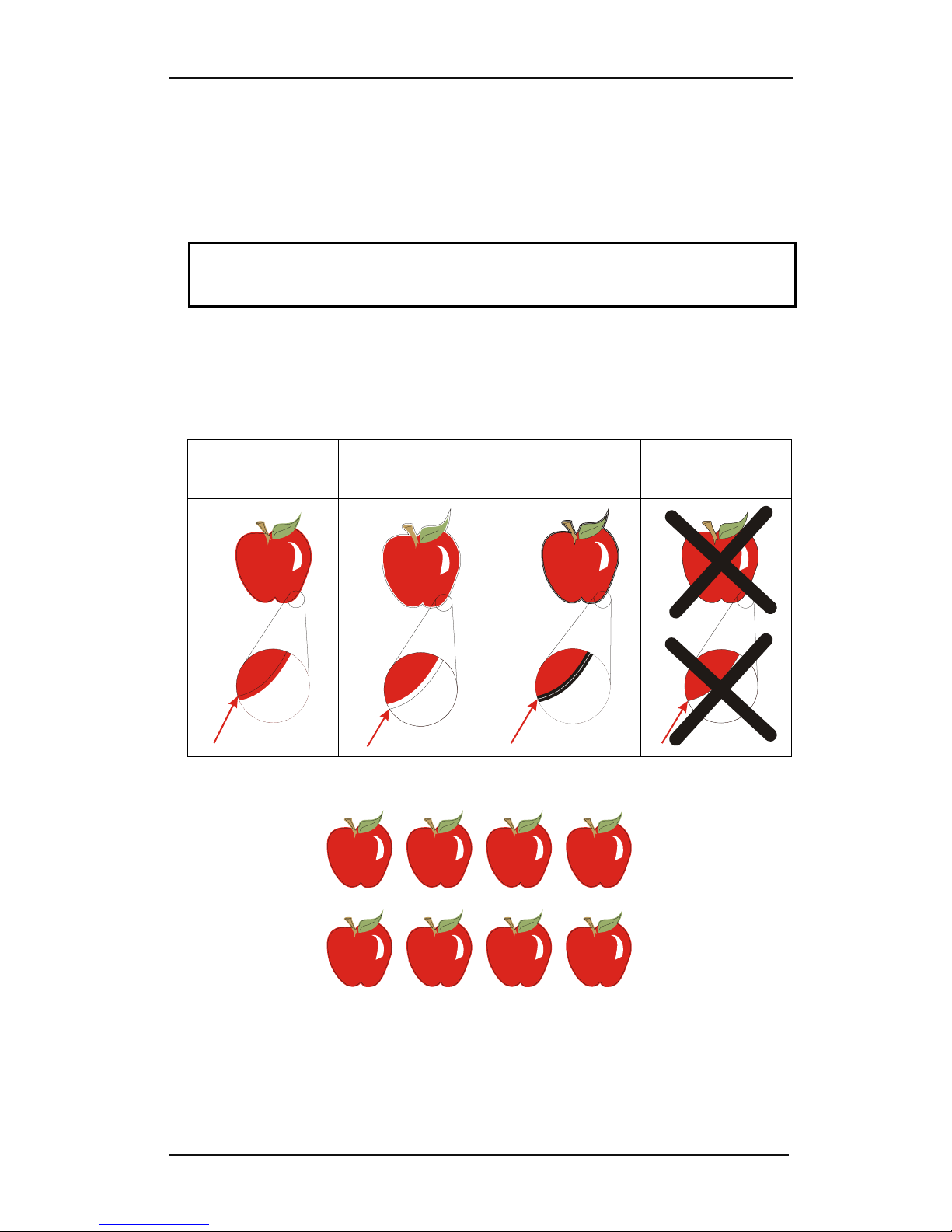
S CLASS™ cutter User’s Manual
Contour Cutting 3-5
3.3 Detailed OPOS Operation
3.3.1 Creating the graphic with the markers
1. Create the graphic and contour cut line(s). For easier handling, place the contour line(s)
on a different layer.
NOTE: Do not place contour lines along the edges of graphics or the slightest
movement in the media may result in an unsatisfactory cut. Instead, practice one of the
following techniques:
Place contour lines just inside the graphics (recommended) (1).
Place contour lines outside the graphics (2).
Create thick borders around graphics and place contour lines inside these borders (3).
(1) contour line
inside graphic
recommended
(2) contour line
outside graphic
(3) contour line
inside a thick border
Contour line on
edge of graphic
2. If necessary, make additional copies of both the graphic and its associated contour.
3. Insert a marker to represent the Origin. The marker must be a black square. Each of the
marker’s four sides should measure 2mm but must not be less than 1.5mm or more
than 10mm. (1=X-size 2=Y-size.)
Page 81
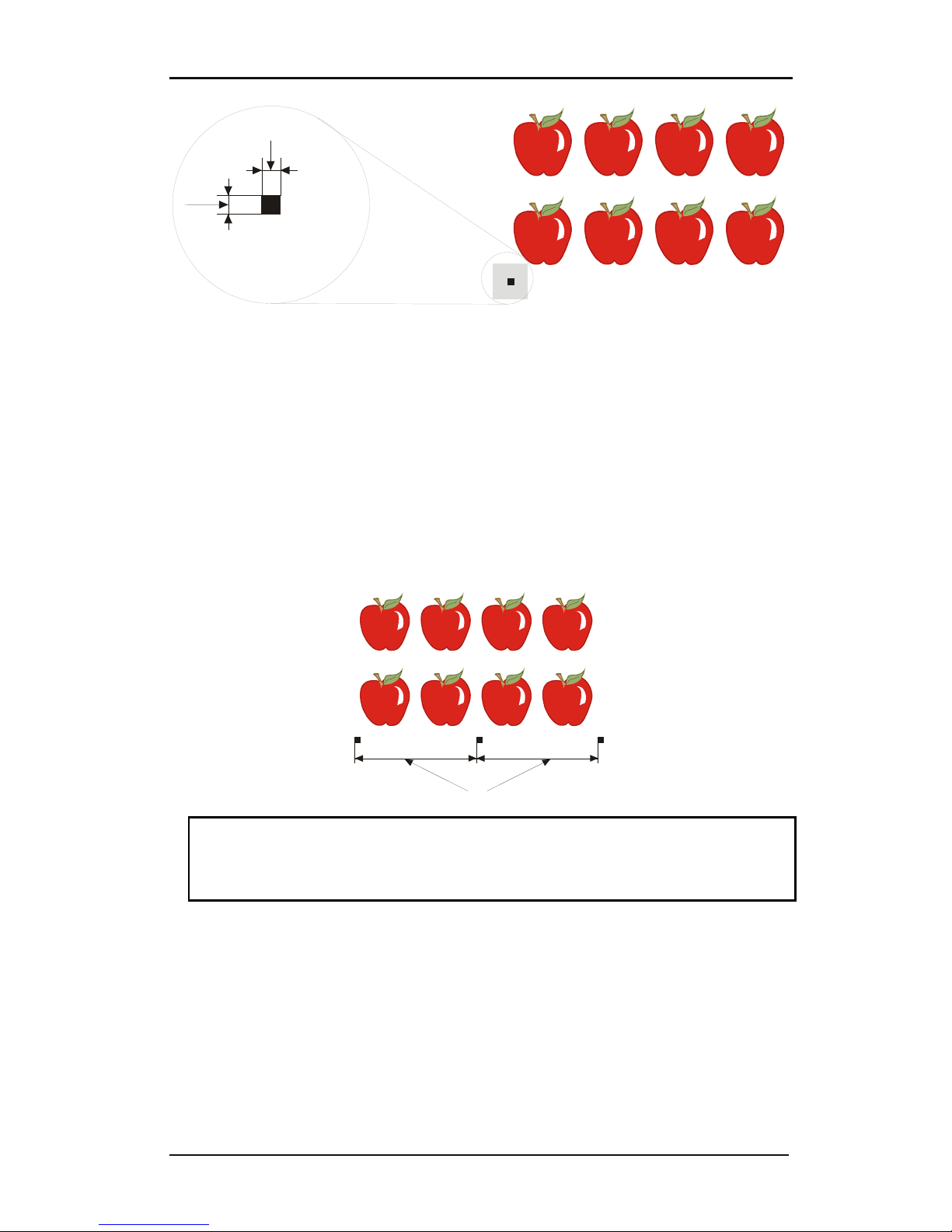
S CLASS™ cutter User’s Manual
Contour Cutting 3-6
1
2
4. Set the line style of the marker to None. Line styles of varying thickness can alter the size
of the markers. Make sure there is a white margin of about 3 to 4 times the marker size
around the marker (in the above picture this area is represented by a gray area). If
anything is printed within this margin, the sensor may be unable to locate the marker.
5. Make sure that the Origin marker is situated below and to the left of all contours to be
cut.
6. Insert horizontally aligned copies of the Origin marker at regular intervals (X-Distance).
Together, these markers indicate the X-Axis.
The X-Distance (1) is the distance from the lower left corner of one marker to the lower left
corner of the next marker and depends on several factors. The X-Distance must be known
when setting the OPOS parameters manually.
1
NOTE: OPOS will operate faster as the X-Distance increases. Conversely, OPOS will
operate more accurately as the X-Distance decreases; however, the impact on accuracy
is minimal. Recommended distance between the markers is 400mm. Maximum XDistance is 1300mm.
7. Make sure there is enough white space around each marker. The X-Distance should be
decreased if the margin of white space around the marker is not 3 to 4 times larger than
the marker itself.
8. Make sure that the markers are perfectly level with one another.
9. Make a copy of the row of markers created in step 5. Place this new row above the
graphic to indicate the Y-Axis.
Page 82
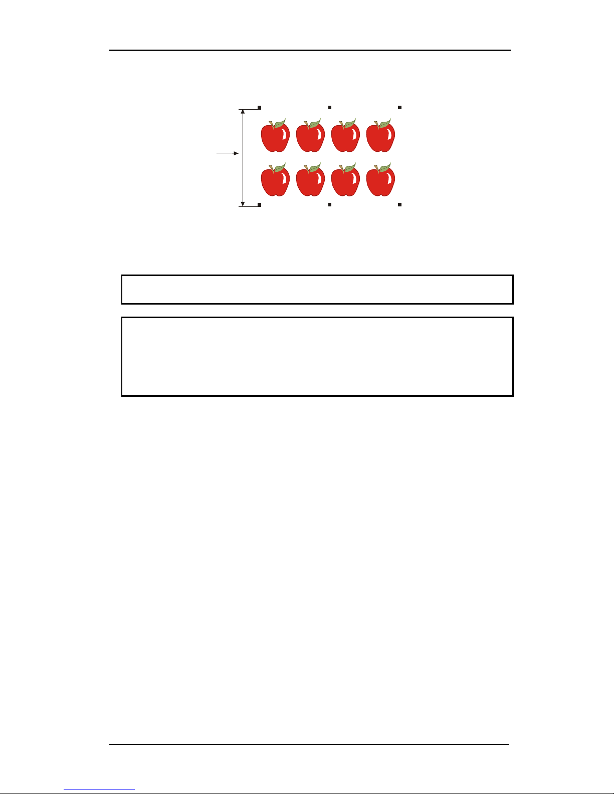
S CLASS™ cutter User’s Manual
Contour Cutting 3-7
The Y-Distance (2) is the distance from the bottom of one marker to the bottom of the next
marker along the Y-Axis. The Y-Distance must be known when setting the OPOS parameters
manually.
2
10. Make sure the two rows of markers have not shifted along the X or Y Axes.
11. Check to be sure that graphics, markers and contour are each in a separate layer. Copy
the origin marker for origin reference in the layer of the contours.
NOTE: The layer with the graphic and the layer with the markers must be printed out.
The layer with the contour lines and the origin reference must be cut out.
NOTE: The optimum marker size depends on the type of printer and the X and Y
distance of the markers.
Inkjet printers with a lot of bleed require slightly larger markers. Some tests will be
needed with the printer in question to decide on the right marker size.
If the X distance is relatively large (> 800mm), then slightly larger markers could be
used.
Page 83
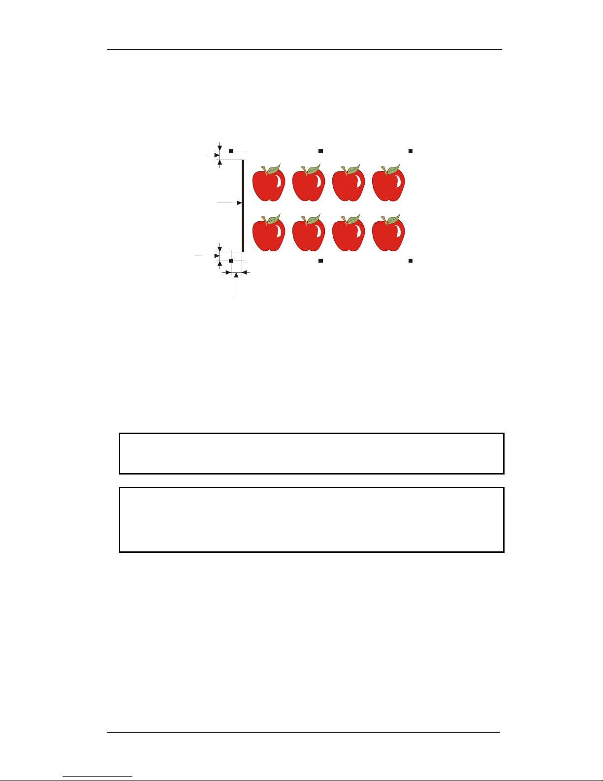
S CLASS™ cutter User’s Manual
Contour Cutting 3-8
3.3.2 OPOS XY
There exists a function in OPOS to compensate for curved printing errors in the Y axis also.
This is called OPOS XY. An extra line needs to be printed with the design to be able to use
the OPOS XY functionality.
2
1
2
3
The line may be added between or above the front Y markers. The distance between the
centre of the markers and the line should not be more then 20mm( distance 1). The left and
right margin between line and marker should be 10mm for optimal sensing (distance 2).
The line itself should be 1mm thick. It is not necessary to have a white area between the
extra line and the rest of the design.
When OPOS XY is enabled, then the OPOS sensor will measure points along the extra line.
The number of measuring points will be calculated by the cutter and will depend on the
width of the design.
NOTE: The default setting for OPOS is OPOSX. If the OPOS XY functionality is needed,
then the user must set change the setting ‘alignment mode’ in the Opos Setup to OPOS
XY by hand on the control panel (see section 4.3.1.4) or via the cutting software.
NOTE: Some cutting software do not support the OPOS XY feature. If they also send the
alignment command ‘OPOS’ to the cutter, then they block the OPOS XY feature of the
cutter. If it is possible to define a line by hand in the design so that it meets up to the
specifications above, then the blocking of the software can be neutralized by using the
setting: ‘FORCE OPOS XY’ in the alignment mode.
Page 84
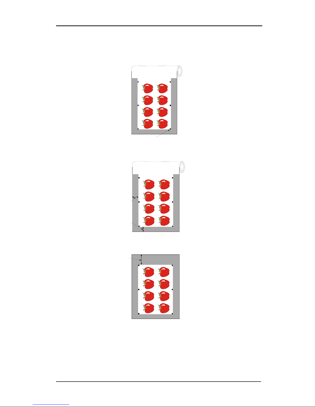
S CLASS™ cutter User’s Manual
Contour Cutting 3-9
3.3.3 Printing the graphic
1. Print the graphic and its markers with a printer (scale = 100%). When printing on a roll,
make sure that the graphic’s Origin marker coincides with the media’s origin (1).
1
2. Make sure there is at least a 1cm (0.4in) margin on each side of the graphic (2). A 2cm
(0.8in) margin is preferable. There must also be a front margin of 1 cm (3).
2
3
3. Leave a margin of at least 4cm (1.6in) following the print when using sheets or when
cutting the print off a roll (4).
4
Page 85
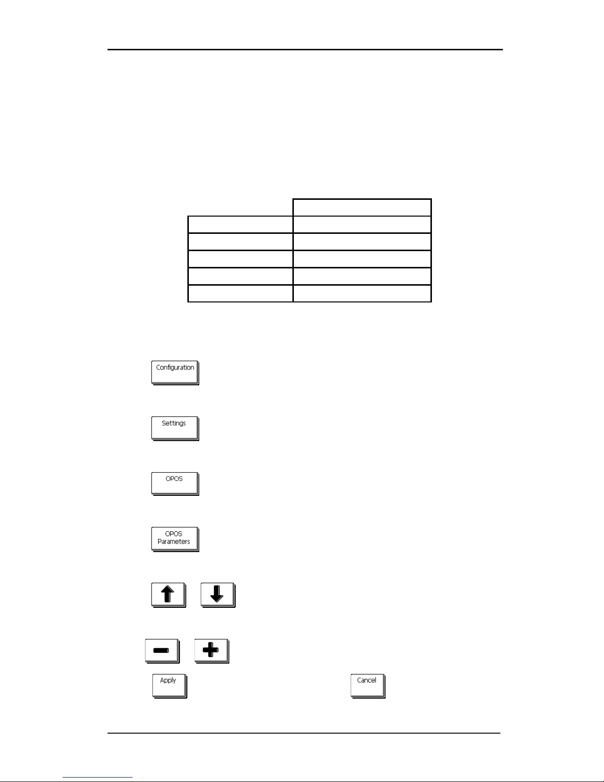
S CLASS™ cutter User’s Manual
Contour Cutting 3-10
3.3.4 Loading the graphic into the cutter
Load the printout into the cutter as described in section 1.5. Make sure that the marker
indicating the Origin is situated at the bottom right corner of the cutter.
3.3.5 Setting the parameters for the OPOS sensor
The OPOS parameters are variables that define the distance, size, and number of markers.
Most cutting software sets these parameters automatically and even starts the special load
procedure.
Range
X distance 30 mm to 1300 mm
Y distance 30 mm to 1600 mm
X size 1.2 mm to 10 mm
Y size 1.2 mm to 10 mm
Marker Count on one line 2 to 64
Changing OPOS setting:
1. Power on the cutter.
2. Press .
The main menu will appear on screen.
3. Press .
The configuration menus will appear on screen.
4. Press .
The different OPOS configuration menus will appear on screen.
5. Press .
The different OPOS parameters will appear on screen.
6. Press or to select the parameter that needs to be changed.
The chosen parameter will be inverse.
7. Use or to change the value.
8. Press to confirm the new values. Or Press to exit the menu without
changing the value.
Page 86
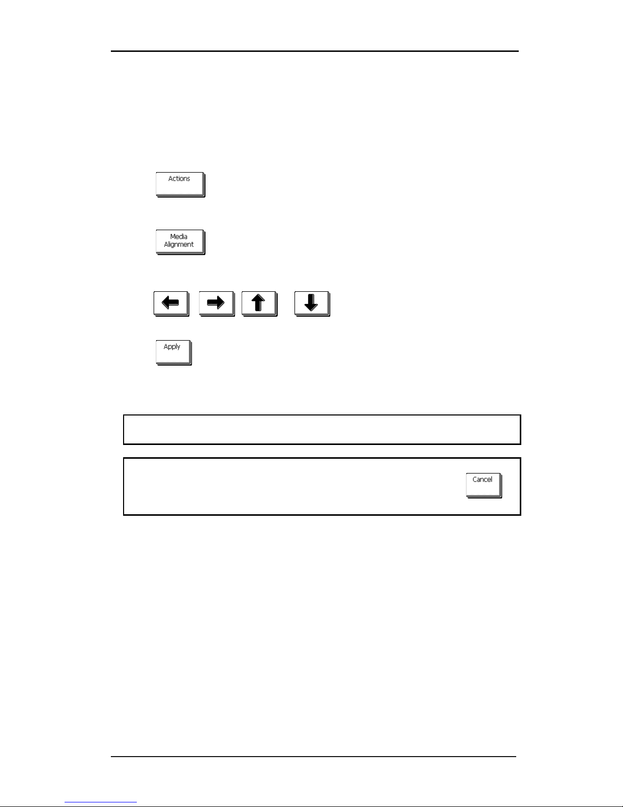
S CLASS™ cutter User’s Manual
Contour Cutting 3-11
3.3.6 Registering the markers
Most cutting software will initiate the special load procedure after the parameters are sent.
If the software does not do this, then initiate the loading sequence from the cutter’s touch
panel.
Registering the markers:
1. Press .
The main action menu will appear on the screen.
2. Press .
The cutter will lower the sensor. The display will show the message: ”put knife on first
marker.”
3. Use , , or to maneuver the knife on top of the first
marker.
4. Press to confirm.
The cutter will reload the media to check if the loaded length matches with the OPOS
parameters used. Then it will return and read the markers.
NOTE: If a marker cannot be read, then the user will be given the option to re-position
the knife (sensor) or to abort.
NOTE: If an error occurs or the cutter cannot read the markers after three attempts, the
following message will be displayed: ”Markers could not be sensed, press to
continue.”
Page 87
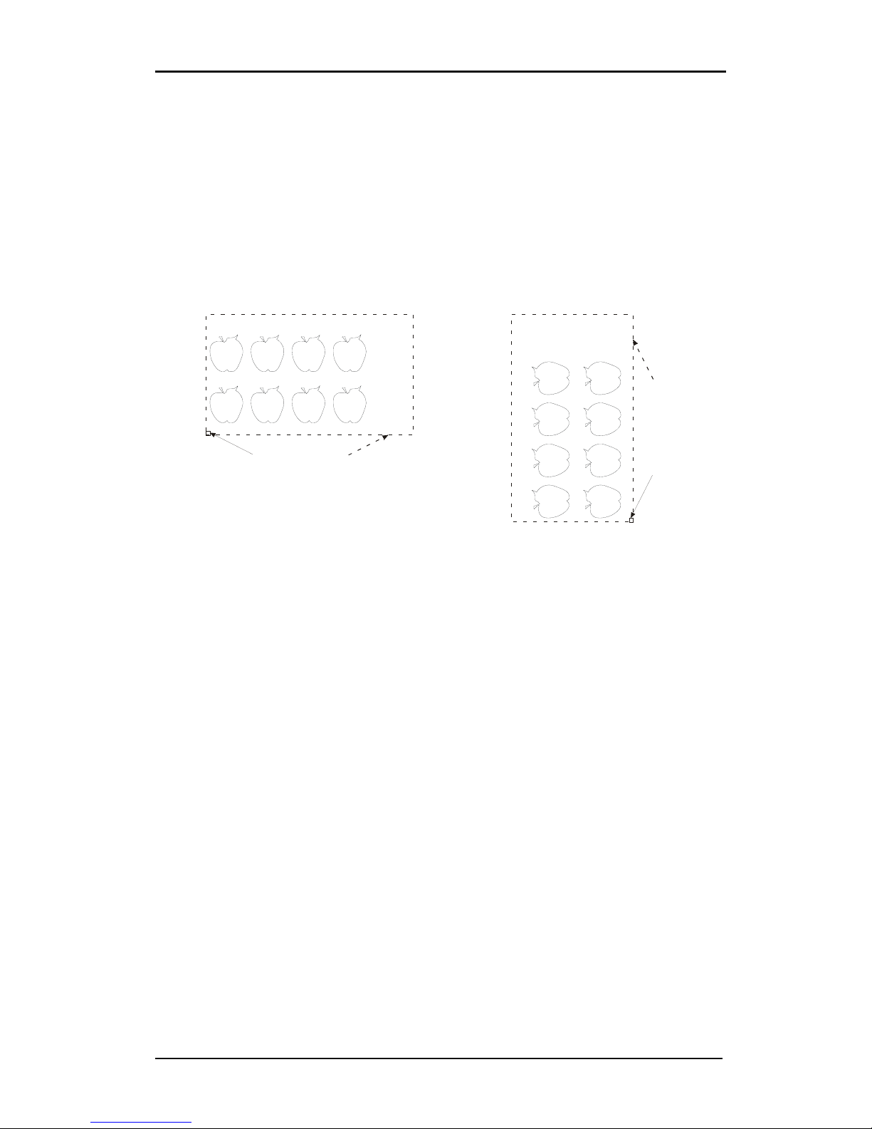
S CLASS™ cutter User’s Manual
Contour Cutting 3-12
3.3.7 Cutting the contour
1. Make the layer containing the contour lines visible and printable. Do the opposite with
the print data.
2. Make sure that the origin marker is also defined as a contour. This will be used as the
origin for the cutting.
3. Once you are using the cutting software, it may be necessary to collectively rotate the
contours and markers so that the Origin marker (1) is situated in the bottom left corner
of the cutting area (2) as viewed on the screen. If your cutting software’s default
orientation is not set to “landscape,” the contours and markers will need to be rotated.
Orientation needed in most cutter software. Orientation when using WinPlot
4. Make sure that the cutter is connected to the computer and that the cutter is switched
on. The cutter’s touch screen should indicate that the cutter is ONLINE.
5. Click Cut from within the cutting software. The cutter should begin cutting the contour
and return to ONLINE status when finished.
1 2
1
2
Page 88
S CLASS™ cutter User’s Manual
Contour Cutting 3-13
3.4 Automating Tasks with OPOS
OPOS allows the user to automate certain tasks, thus reducing user intervention and
production time. When cutting multiple graphics, the user only needs to maneuver the
OPOS sensor above the Origin marker of the first graphic; cutting subsequent graphics does
not require additional user input.
There are two multiple-job situations in which OPOS can be used:
When cutting multiple (copies of a) graphic(s) on the same media roll.
When cutting the same graphic on multiple media sheets.
Most automated tasks are organized from within the cutting software. However, when the
same graphic contour needs to be cut out, then the automatic tasks also involve some
manual manipulation.
Before using the automating features, note the amount of your cutter’s RAM. If the cutter’s
RAM is greater than the job’s file size, then the automating features may be used. If the
cutter’s RAM is less than the job’s file size, then the automating features may not be used.
3.4.1 Cutting multiple copies of a graphic on the same roll
If the same graphic design has been printed on a roll with equal distance between the
different graphics, then this feature can be used.
First, load the media and be sure the parameters of the OPOS markers are set correctly.
Cutting multiple copies of the same graphic on the same media roll:
1. Press .
The main menu will appear on screen.
2. Press
.
The configuration menus will appear on screen.
3. Press .
The general settings will appear on the screen.
4. Press .
The current value of the recut offset will appear on screen.
5. Use or to change the recut offset (the distance between the last cut
vector and the beginning of the first marker).
Page 89
S CLASS™ cutter User’s Manual
Contour Cutting 3-14
6. Press to confirm the new value, or press
to exit the menu without
changing the value.
7. Press to get online again.
8. Register the markers and cut the first contour as described in sections 3.3.5 and 3.3.6.
The cutter will stop after the first contour has been cut and come online again.
9. Press .
The main action menu will appear on the screen.
10. Press .
11. Use or to change the number of recuts displayed.
12. Press to confirm the new value, or press to exit.
OPOS will sense the markers for the second contour and then cut that contour. This process
of sensing and cutting will repeat automatically until all remaining contours have been cut.
3.4.2 Cutting the same graphic on multiple media sheets
If the same graphic design has been printed on a multiple sheets, then this feature can be
used.
NOTE: The sheets should be more or less the same size, and the graphics on them
should be oriented and positioned the same way.
First, load the media and check that the parameters of the OPOS markers are set correctly.
Cutting the same graphic on multiple media sheets:
1. Press .
The main option menu will appear on the screen.
2. Press .
The different configuration menus will appear on screen.
Page 90
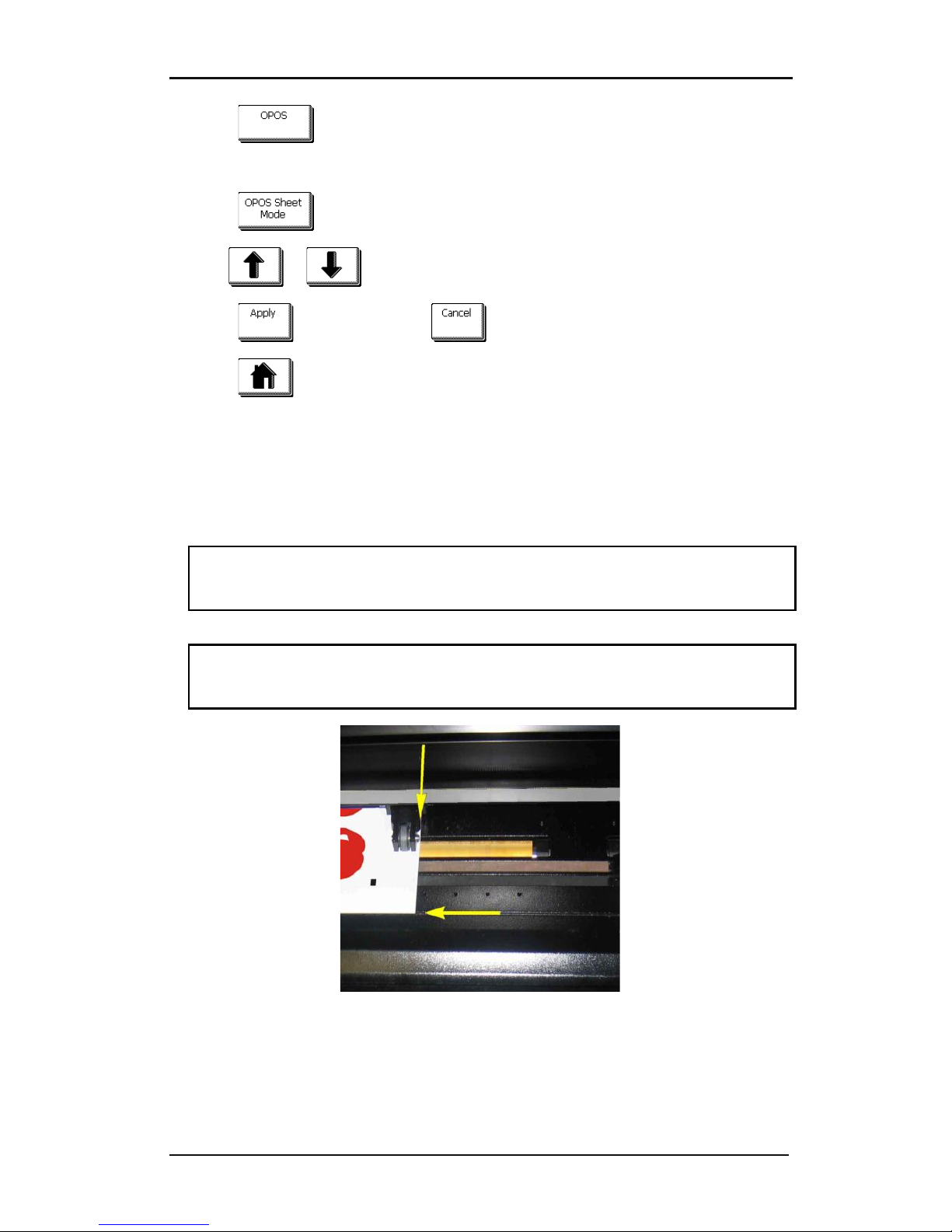
S CLASS™ cutter User’s Manual
Contour Cutting 3-15
3. Press .
The different OPOS configuration menus will appear on screen.
4. Press .
5. Use or to set OPOS sheet mode “on” or “off.”
6. Press to confirm, or press to exit.
7. Press
to get online again.
8. Register the markers and cut the first contour as described in sections 3.3.5 and 3.3.6.
The cutter will stop after the first contour has been cut and come online again.
9. Raise the pinch rollers and manually remove the sheet.
10. Insert the next sheet into the cutter. Lower the pinch rollers.
NOTE: The second and any following sheets must be loaded in the cutter at the same
position as and with the same orientation of the first sheet. When in OPOS sheet mode,
the cutter stores the distance between edges of the sheet and the first OPOS marker.
TIP: Use easy orientation points to be able to quickly position the sheet. In the figure
below, a rim of the base plate and the side of the pinch roller assembly are used to align
the sheets.
FIG 3-1
3-1 POSITION MEDIA FRO MULTIPLE SHEET
Page 91
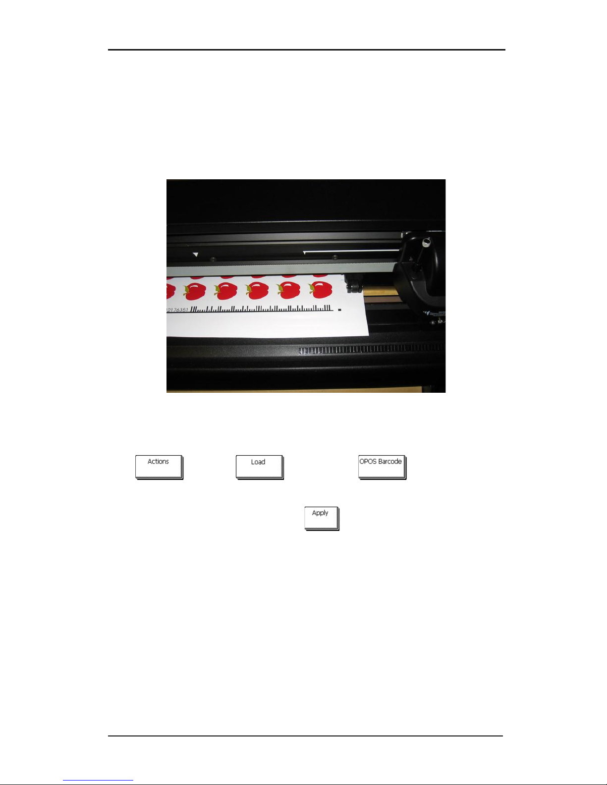
S CLASS™ cutter User’s Manual
Contour Cutting 3-16
3.4.3 OPOS Barcode
The S class cutters can also read a barcode. Certain RIP’s have the ability to print a barcode
together with the OPOS markers. This barcode can then be used to identify the job and
retrieve the needed cut data automatically from the computer.
The complete procedure is normally started from the computer. The cutting software will
usually have a button or a command called ‘scan a bar code’. First make sure that the media
is loaded.
FIG 3-2
3-2 OPOS BARCODE JOB LOADED
Start the procedure from the computer or start from the touch screen.
To start from touch screen:
Press , then press and finally press .
The cutter will prompt the user to put the knife under the barcode.
Do so by using the arrow keys. Then press on .
The cutter will read the barcode and send this data to the computer.
The cutting software will then automatically send the correct cutting data to the cutter.
The cutter will start sensing the OPOS markers and cut out the job.
After that the OPOS sensor will search if there is a job printed after the one that is just
finished and continue to contour-cut..
This will repeated until the all contour-cut jobs on the loaded roll are cut out.
Page 92
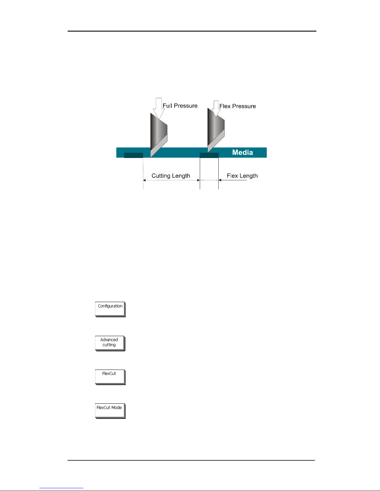
S CLASS™ cutter User’s Manual
Contour Cutting 3-17
3.5 Cutting through
The cutting through functionality is focussed to cut simple shapes (e.g. rectangles). It is
most used in combination with contour cutting.
An interrupted cutting line makes sure that the material remains together thanks to the
small media ‘bridges’. When the job is finished the cut pieces can be torn out.
FIG 3-3
3-3 FLEXCUT PRINCIPLE
Some cutting software can recognize the difference between a contour line and a cutthrough line. The software sends then first the data of the contour lines to the cutter, and
then it activates FlexCut, panelling mode and vector sorting and sends the data for cutting
through to the cutter.
If the cutting software cannot do this, then the user needs to first send the data of the
contour lines separate, set the cutter manually in FlexCut mode and then send the data for
cutting through.
Setting the parameters for cutting through the media:
1. Power on the cutter.
2. Press .
The main menu will appear on the screen.
3. Press .
The advanced cutting menu will appear on screen.
4. Press .
The FlexCut menu will appear on screen.
5. Press .
The menu to activate or deactivate FlexCut will appear on screen.
Page 93
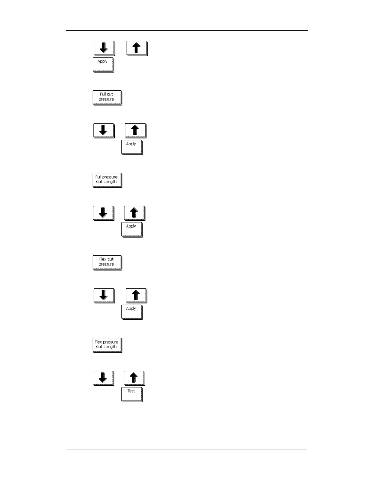
S CLASS™ cutter User’s Manual
Contour Cutting 3-18
6. Press or to choose FlexCut mode (accurate is recommended) and
press to confirm.
The FlexCut menu will appear on screen.
7. Press .
The menu to change the full (cut through) pressure will appear on screen.
8. Press or to change the pressure (180 gr is a recommended starting
value) and press to confirm.
The FlexCut menu will appear on screen.
9. Press .
The menu to change the cutting length at full pressure will appear on screen.
10. Press or to change the cut length (10mm is a recommended starting
value) and press to confirm.
The FlexCut menu will appear on screen.
11. Press .
The menu to change the flex (bridge) pressure will appear on screen.
12. Press or to change the pressure (80 gr is a recommended starting
value) and press to confirm.
The FlexCut menu will appear on screen.
13. Press .
The menu to change the cutting length at flex pressure will appear on screen.
14. Press or to change the cut length (0.8mm is a recommended starting
value) and press to confirm.
The cutter will cut out a test pattern.
Page 94
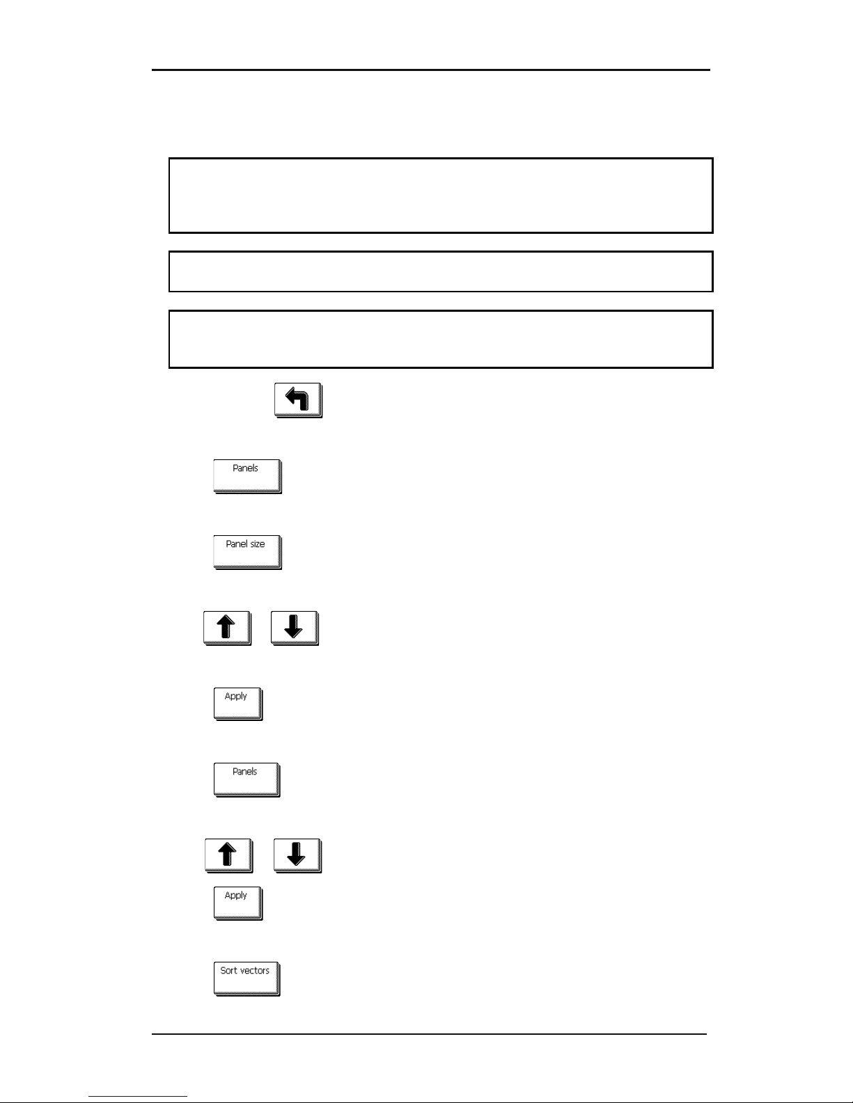
S CLASS™ cutter User’s Manual
Contour Cutting 3-19
15. Check if the result is the satisfactory. If not change one of the 4 parameters above.
Reducing the velocity can also improve the result. It is never recommended to use
cutting speeds larger then 400mm/s (16 ips) with cutting pressures above 170 gr.
Note: It is not always easy to find the correct balance between cutting deep enough
making sure the pieces can be taken out easily, and not cutting too deep making sure
the material keeps it strength while cutting. Sometimes this balance doesn’t exist
meaning that this material can’t be cut through with satisfactory result.
Note: FlexCut parameters are always metric, regardless the value of the panel Units
parameter (see section on Panel Units:)
Note: When cutting through, it is recommended that parallel lines are at least 1 cm
away from each other. Otherwise, while cutting the second line, the first line may come
loose and cause trouble.
16. After that press .
The advanced cutting menu will appear on screen.
17. Press .
The paneling menu will appear on screen.
18. Press .
Current panel size will appear on screen.
19. Use
or to set paneling size, recommended values are 3 to 10cm.
New value will change.
20. Press to confirm.
The paneling menu will appear on screen.
21. Press .
The menu to disable or enable paneling will appear on screen.
22. Use or if necessary to enable paneling.
23. Press to confirm.
The paneling menu will appear on screen.
24. Press .
Page 95
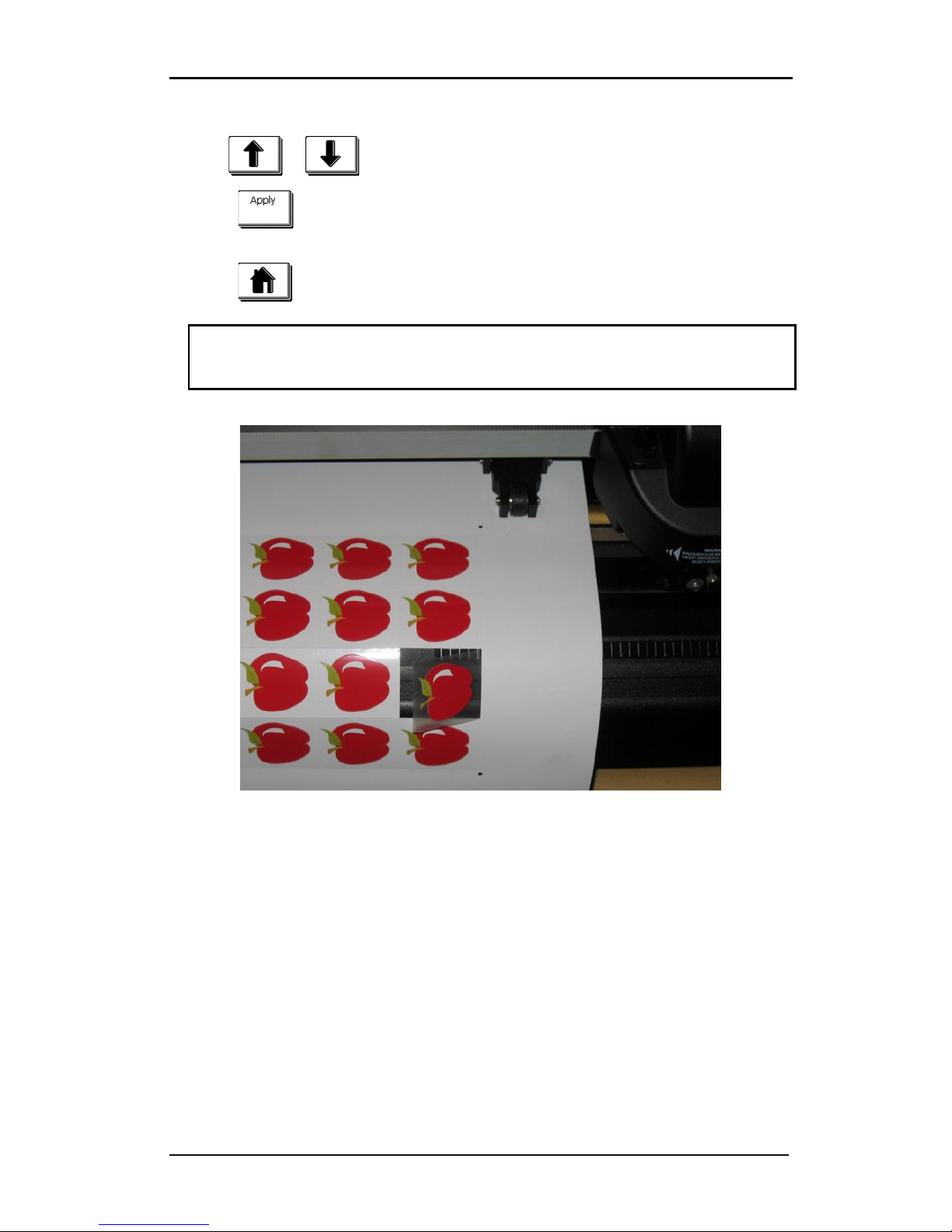
S CLASS™ cutter User’s Manual
Contour Cutting 3-20
The menu to disable or enable vector sorting will appear on screen.
25. Use or if necessary to enable vector sorting.
26. Press to confirm.
The paneling menu will appear on screen.
27. Press to set the cutter online again.
Note: The above procedure has to done even if the software on the computer can
activate FlexCut. Only steps 5-6 and 21-26 may be skipped, because the command from
the computer will activate those parameters automatically.
FIG 3-4
3-4 COMBINED CONTOUR CUT AND CUTTING THROUGH
Page 96
Detailed Operation 4-1
4 Detailed Operation
4.1 Introduction
This section is a detailed list of all parameters that can be changed and tests that can be
initiated from the touch screen.
Section 1 and 2 of this manual describe in detail the most commonly used touch screen
manipulation.
This section may be used as a reference for locating a certain parameter setting or test. The
less frequently used parameters are also explained in this section.
4.2 Action Menu
FIG 4-1
4-1 ACTION MENU
Most of the explanation of this menu is covered in previous sections.
Set Origin: Used to change the origin of the tool carriage on a loaded piece of media.
After this button is pressed, arrow keys will appear to allow the user to go to the new origin.
Load: The loading procedure is explained in section 1.5.4.
Reset: Used to interrupt an ongoing job.
Media alignment: Starts the loading procedure for contour cutting; see section 3.3.6.
Replot: Each job is stored in the cutter’s memory until a new job is sent. Pressing replot
allows the job to be replotted. After this button is pressed, the user may choose the number
of replots. The replot button does not work if there is no job in the memory, or if the
previous job was larger than the cutter’s memory.
Cut off: Moves the media till after the last cut vector and cuts off from the roll with the cut
off knife.
Actions
Load
Roll Sheet
Set Orig in
Reset
Media
Alignment
Replot
Extended
Cu t o ff
OPOS Barcode
Roll u p m ed ia
(*) Only whe n roll up is enabled
Page 97
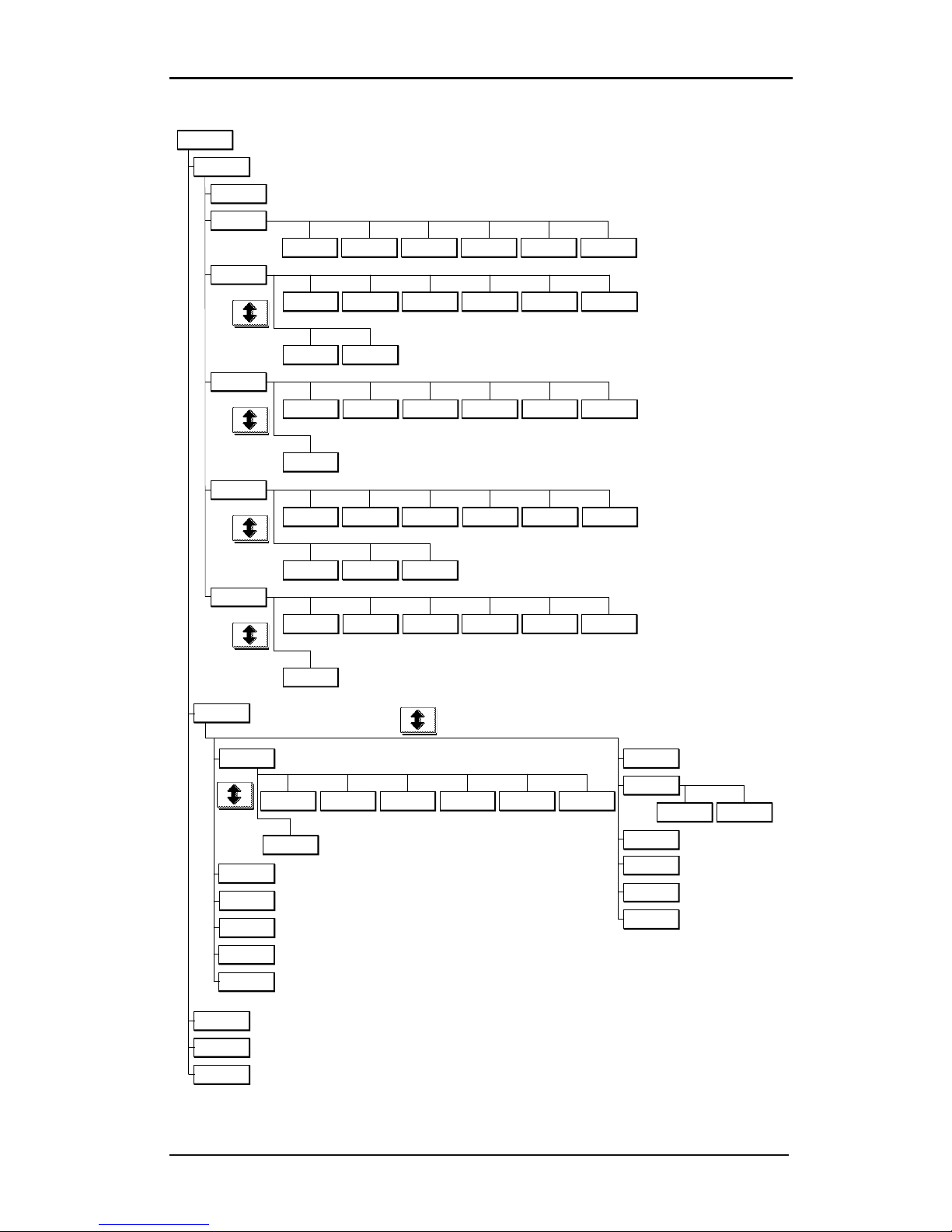
S CLASS™ cutter User’s Manual
Detailed Operation 4-2
Configuration
Advanced
Cutting
Overcut OptiCut FlexCut Panels Smoothing
Settings
Tool
General
Media Sensor
Autoload
Language
Front margin
Menu Units Recut Offset Cut off margin
OPOS
Calibrate OPOS Calibrate media
(OPOS)
Alignment
mode
OPOS sheet
mode
OPOS
Parameters
Communication
Baudrate
(RS232)
Parity (Rs232)
RTS/DTR
(RS232)
Velocity in
detail
Velocity Up velocity Down
acceleration
Up
acceleration
Long vectors
Tests & Setup
Length
calibration
Calibrate knife
Factory
Default s
Media sensor
setup
Back Sensor Front Sensor
OPOS
Calibrate OPOS Calibrate
media ( OPOS)
Alignment mode OPOS sheet
mode
OPOS
parameters
Coil setup
Confidence test
DIN A4 Test
RS232 Test
Velocity
Tool properties
User
(*) Tool properties will vary according to the chosen tool
Rom Revision
Emulation
Language
Tool commands
DMPL
addressing
(*) Only when tangential tool is the current tool
Calibrate touch
screen
(*) Only when drag knife is the current tool
Copy current
user
Roll up media
(*) Only when roll up is enabled
(*) Only when drag knife is the current tool
Concatenation
TurboCut
OPOS panels
Monitor
USB Class
HPGL Origin
Wireless
FlexCut
velocity
(*) Only when option is installed
Monitor
Monitor
4.3 Configuration Menu
FIG 4-2
4-2 CONFIGURATION MENU
Page 98
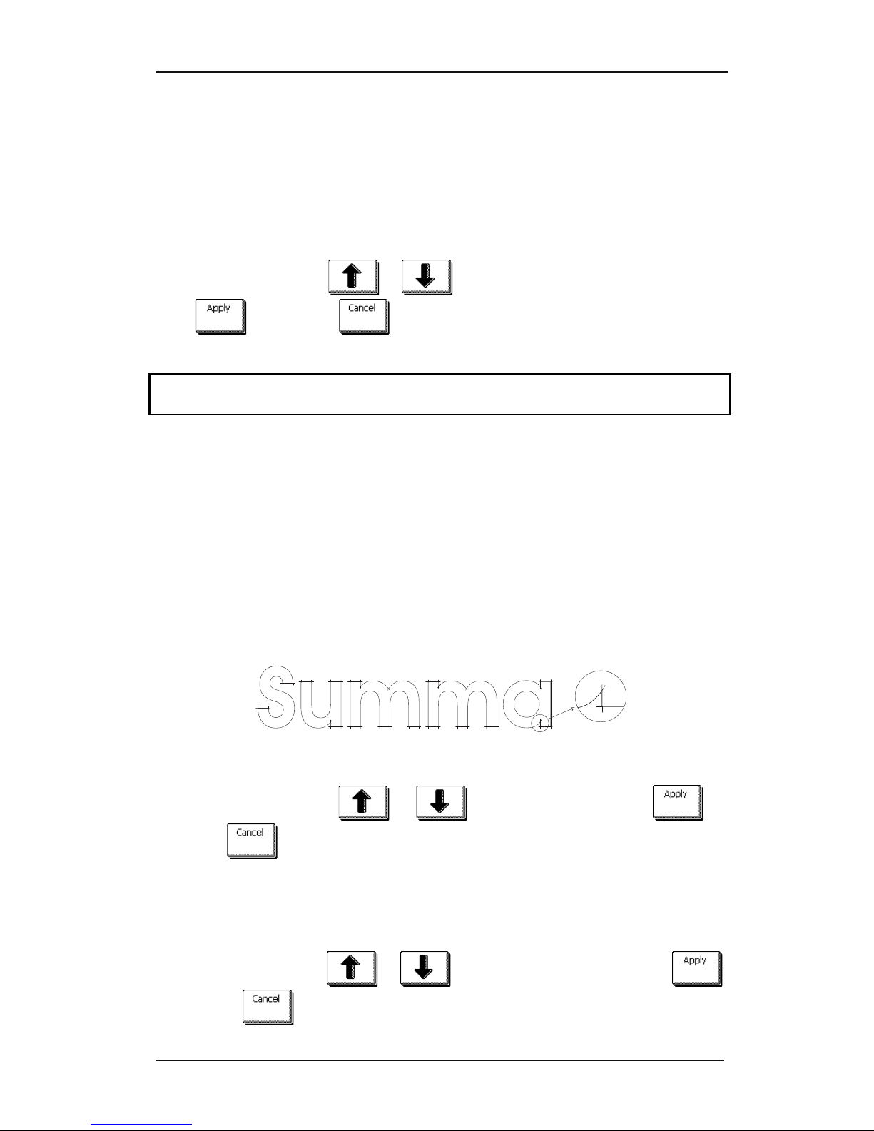
S CLASS™ cutter User’s Manual
Detailed Operation 4-3
4.3.1 Settings
This menu bundles all the settings of the S CLASS™ cutters. All settings in this section, apart
from the OPOS parameters, are user-dependent (information is contained within each of
the eight individual user settings, see section 4.3.3.).
4.3.1.1 Tool
The Tool submenu is used to select the default tool at power-up.
Press the button, then use or to change the tool to another default tool.
Press to confirm or to cancel. After changing the tool, the cutter will ask
the user to confirm that there was a tool change just before it comes online.
NOTE: Do not forget to check and/or recalibrate the tool settings when a tool has been
changed (see section 2.2.1). Also, OPOS calibration must be redone (see section 3.2.1).
4.3.1.2 Advanced cutting
The cutting menu groups the different parameters to optimize the cutting quality.
Overcut:
The Overcut submenu enables you to generate an overcut in order to facilitate weeding the
cut. Each time the knife goes up or down, the cutter cuts a bit further. Figure 4.3 below
shows what overcut does with a tangential knife. A sample cut-out with a drag knife would
show fewer overcuts, since there would be fewer up/downs (usually only one per
curve/letter).
The overcut setting can be disabled (=0) or set to any value between 0(=off) and 10. One
unit is about 0.1 mm or 0.004 ".
FIG 4-3
4-3 OVERCUT
Press the button, then use or to change the value. Press to
confirm or to cancel. The default overcut is set to 1.
OptiCut:
OptiCut increases the cutting quality in case the knife is worn out or not calibrated correctly.
OptiCut is default-set to OFF.
Press the button, then use or to set OptiCut to ON or OFF. Press
to confirm or to cancel.
Page 99
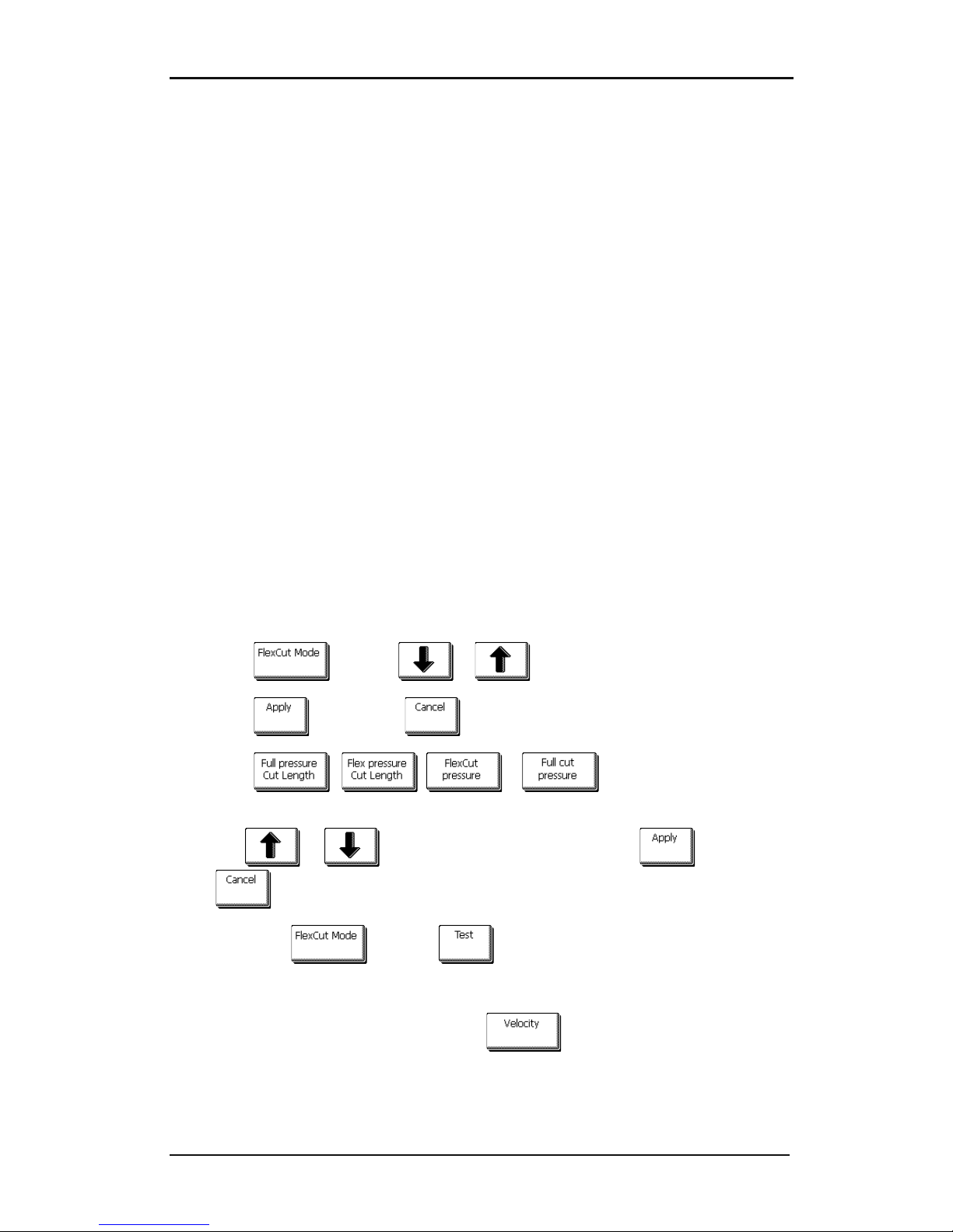
S CLASS™ cutter User’s Manual
Detailed Operation 4-4
FlexCut:
FlexCut can be set to OFF, Fast, or Accurate. When the cutter is set to Fast or Accurate, it will
alternately cut a certain length with full pressure, and a certain length with reduced
pressure. The advantage of the FlexCut feature is that it cuts completely through the
material, yet allows the material to stay together by means of the small media bridges.
Fast is the quickest mode, but it is less precise due to the pressure changes during the
cutting.
Accurate is much slower, but much more precise, as the cutter stops at every change of
pressure.
There are 4 typical FlexCut parameters:
1. Full pressure: This parameter determines full pressure used during FlexCut mode.
2. Full pressure cut length: This parameter determines the length that is cut with full
pressure, usually the length that will be cut all the way through.
3. Flex pressure cut length: This parameter determines the length that will be cut with
reduced pressure or without pressure. This is usually a much smaller value than the
full pressure cut length – this is the length of the media bridges.
4. FlexCut pressure: This parameter determines the pressure of the Flex pressure cut
length. This is usually a reduced pressure so that the knife only scratches the media or
cuts it only halfway through.
Procedure to set the correct parameters for FlexCut:
1. Press
then use
or
to choose the FlexCut mode.
2. Press to confirm or to cancel.
3. Press , ,
or
to select the parameter that
must be changed.
4. Use or to change to the desired value, press to confirm or
to cancel.
5. Go back to
and press
to check the result.
6. Repeat steps 3 through 4 until the desired result is achieved.
7. If necessary change velocity by pressing
Page 100

S CLASS™ cutter User’s Manual
Detailed Operation 4-5
Panels:
There are 4 specific parameters in the ‘Panels’ submenu:
1. Panels: This parameter switches panels on or off.
2. Panel size: This parameter determines the length of the panel.
3. Panel replot: This parameter determines if the design has to be cut more than once on
top of itself, this per panel. Panel replot is used for thick media and media which is
difficult to cut. The value of this parameter is disregarded if paneling is set to off. If
this parameter is set at 0, then the cutter will cut each panel only once. If it is set at 1,
it will cut each panel twice,…
4. Sort vectors: See paragraph below
Paneling is used for several different applications. Below are the typical settings for the
most 3 common applications.
Cutting through: This is explained in section 3.5. Typical settings for the parameters are then:
Panels: ON; Panel size 5 – 10cm; Panel replot: OFF; vector sorting: DIRECTIONAL.
Tracking difficult media: This is explained in section 2.7. Typical settings for the parameters
are then: Panels: ON; Panel size 3 – 10cm; Panel replot: ON/OFF depending on the thickness
of the media; vector sorting: DRIECTIONAL/OFF depending on needed knife pressure and
backing of the material.
Roll Up: The roll-up system is an option that can be added on the larger S CLASS models
refer to the manual for the roll-up system for more info. Typical settings for the parameters
are then: Panels: ON; Panel size 50 – 100cm; Panel replot: OFF; vector sorting: OFF. Another
recommended setting when using the roll-up system is to set panels to off and use the
automatic paneling of 100cm and set roll-up to ‘AFTER AUTO-panel’. See section on ‘Roll up
media:’
Sort Vectors:
Sorting vectors is a sub menu of the panel menu, but because of its importance explained
separately.
There are three options in this menu.
1. Off: When vector sorting is set of, then the cutter does no optimizing of the vectors.
This is used when the intelligence of the cutter driver is preferred.
2. Directional: If set to directional, then the vectors are optimized for cutting direction
(media movement). This used when the cutting pressure has to be set relatively high (
for example with cutting through).
3. Starting point: This option optimizes the starting point for closed curves. This is used
when the users sees that the curves do not close as they should.
 Loading...