

Sumitomo Bevel BUDDYBOX 4 Series, LH Series, Bevel BUDDYBOX 5 Series, Helical BUDDYBOX, Bevel BUDDYBOX 3 Series Maintenance Manual
...
Trained technicians should handle, install, and maintain the gearmotor and reducer.
Make sure to read the maintenance manual carefully before use.
A copy of this maintenance manual should be given to the actual user.
Actual user should always keep this manual at hand.
BUDDYBOX
®
Right-angle : Bevel BUDDYBOX
®
Parallel : Helical BUDDYBOX
®
No.CM2020E-2
Maintenance Manual
CAUTION

1
Matters described in may lead to serious danger depending on the situation. Be sure to observe
important matters described herein.
DANGER
Properly trained technician with knowledge should transport, install, plumb, wire, operate, maintain, and inspect
the unit. Otherwise, electric shock, injury, fire, or damage to the equipment may occur.
For explosion proof motor: Properly trained technician with knowledge should transport, install, plumb, wire,
operate, maintain, and inspect the unit. The technician should have knowledge on each explosion proof structure,
electric facility, related law, principles and functions. Otherwise, electric shock, injury, fire, or damage to the
equipment may occur.
Use a secondary safety device on the unit when using for passenger transportation. Otherwise, accident may
occur resulting in injury or death and equipment damage by overdrive and drop.
Use a secondary safety device on the unit when using for elevators. Otherwise, accident may occur resulting in
injury or death and equipment damage by drop of the car.
(
Safety precautions
)
Read this maintenance manual and all accompanying documents thoroughly before use. Understand the machine,
information on safety, and all precautions for correct operation.
Make sure you understand all of the knowledge on the unit and precautions on safety. Always keep this manual handy
after reading this manual.
There are two levels of safety precaution in this catalog, "DANGER" and "CAUTION."
DANGER
CAUTION
CAUTION
: Incorrect handling of the unit may cause physical damage, serious personal injury,
and/or death.
: Incorrect handling of the unit may cause physical damage and/or personal injury.
2
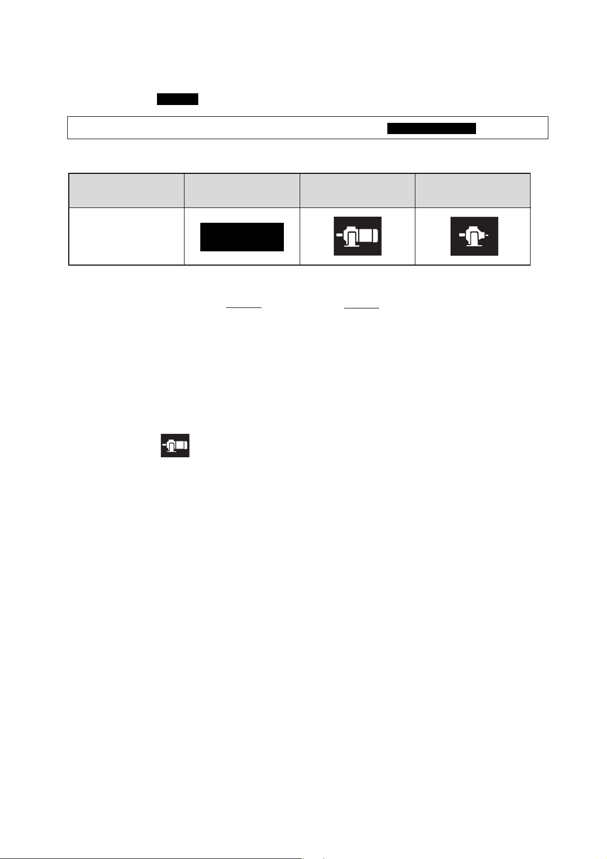
Classification
Common specifications
Gearmotor Reducer
Symbol
COMMON
(How to Use the Maintenance Manual)
This maintenance manual is common for both gearmotor and reducer. The symbols shown below are in the upper right hand
corner of each page to show classification. Read the necessary pages. Symbols identify distinctions between gearmotors
and reducers, even on COMMON pages.
• Refer to the brake maintenance manual (Cat. No.MM0202E) for the handling of gearmotors with brake .
CONTENTS
1. Inspection Upon Delivery............................................................................................................. 3
2. Storage ....................................................................................................................................... 8
3. Transportation ............................................................................................................................ 8
4. Installation .................................................................................................................................. 9
5. Coupling with Other Machines ................................................................................................. 10
6. Wiring ................................................................................................................... 19
7. Operation ................................................................................................................................. 22
8. Daily Inspection and Maintenance ........................................................................................... 23
9. Troubleshooting ....................................................................................................................... 35
10. Construction Drawing ............................................................................................................. 37
11. Warranty ................................................................................................................................. 42
3
COMMON
1. Inspection Upon Delivery
CAUTION
Make sure that the unit is positioned right side up before unpacking. Otherwise, injury may occur.
Make sure that the unit agrees with your order. Injury or damage to the equipment may occur by using the
incorrect product.
Do not remove the nameplate from the unit.
Make sure of the following when this product arrives.
1. Do the items shown on nameplate agree with the order?
2. Was there no damage during transportation?
3. Are all bolts and nuts tightened firmly?
Consult our agent, distributor, or sales office for any defect or questions.
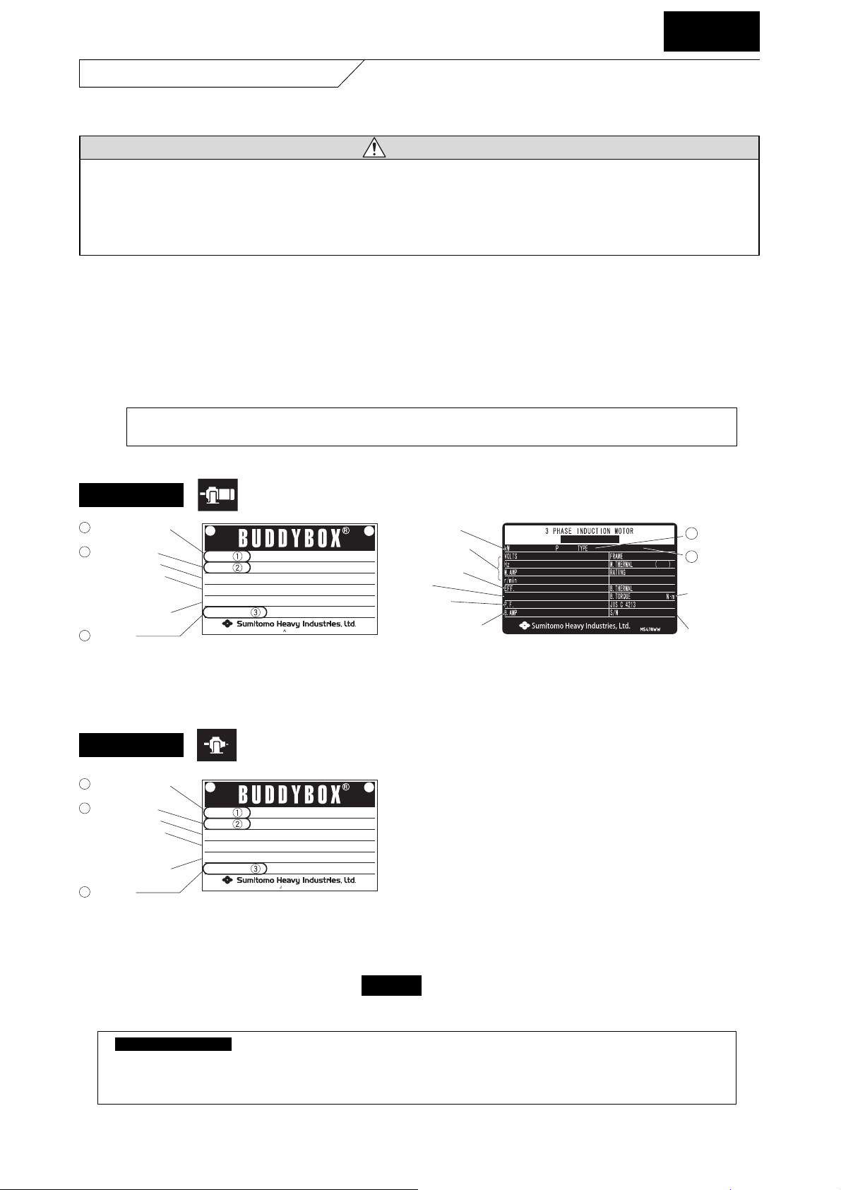
1-1) Inspection of the Nameplate
Gearmotor
Fig. 1 Nameplate of Gearmotor
Reducer
Fig. 2 Nameplate of Reducer
1-2) Inspection of Lubrication Method
Make sure of the lubrication method by referring to section "8-2. Lubrication Method" on page 24.
• Oil lubrication models are shipped with out oil. Always supply the unit with recommended oil before operation.
• Oil supply for two places is necessary for some models for output side and input side, (such as
combination of BUDDYBOX and CYCLO).
COMMON
Nameplate of Gear Nameplate of Motor
• Let us know the (1) Nomenclature of gearmotor or reducer, (2) reduction ratio, and (3) serial number when
consulting us.
RATIO
INPUT kW
r/min
SERIAL NO.
OUTPUT TORQUE
SERVICE FACTOR
MODEL
N
•
m
R
JAPAN
1 Type of gearmotor
(Refer to page 4.)
2 Reduction ratio
・ Service factor
・ Allowable input
capacity and
speed [r/min]
・ Allowable output
torque
3 Serial No.
Motor capacity
Characteristics of
motor
Motor efficiency
IE code
Power factor
Brake current value
(for the motor with a
brake)
4 Motor
nomenclature
5 Type of brake
(for the motor
with brake)
Serial No.
Brake torque
(for the motor
with brake)
1 Type of reducer
(Refer to page 4.)
2 Reduction ratio
・ Service factor
・ Allowable input
capacity speed
[r/min]
・ Allowable output
torque
3 Serial No.
MODEL
RATIO
SERVICE FACTOR
INPUT kW
OUTPUT TORQUE
SERIAL NO.
JAPAN
R
r/min
•
N
m
4
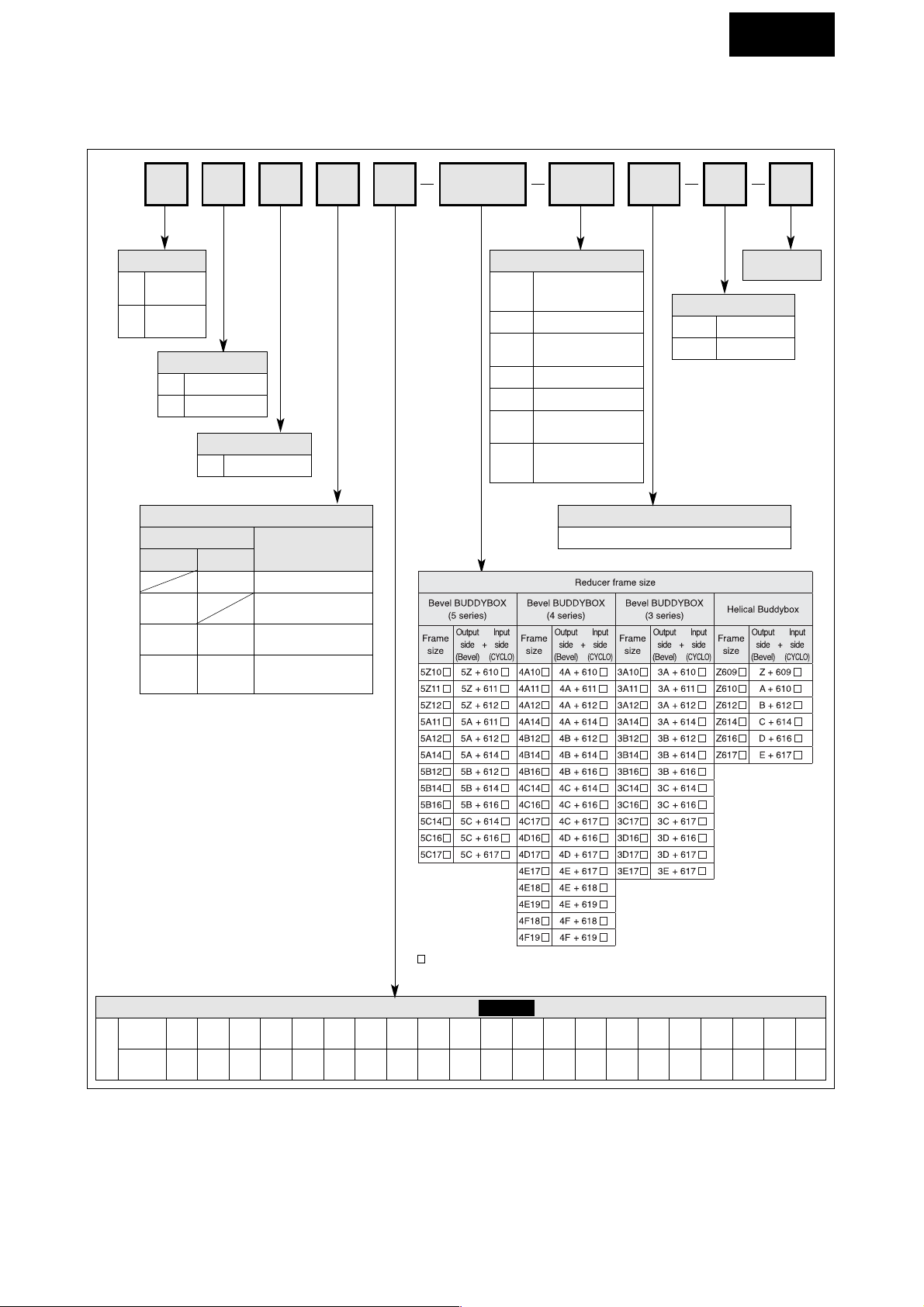
1-3) Inspection of Nomenclature of Gearmotor or Reducer
Nomenclature shows following information. Make sure it agrees with your order.
LM104
C
145 AV B 46
Model
L
E
Bevel
Buddybox
Helical
Buddybox
Mounting style
Y Hollow shaft
Coupling method with driver
Motor
Without With
M
Type of input
Gearmotor
Blank
Reducer
(Both - end shaft type)
Nominal
reduction ratio
Brake
B With brake
Blank Without brake
Mounting position
Refer to Table 1 and Table 2 on page 5-6.
Motor capacity of gearmotor
4 - pole
Capacity
Symbol
01 02
kW
(HP)
0.1
(1/8)
0.2
(1/4)
03
0.25
(1/3)
05
0.4
(1/2)
08
0.55
(3/4)
1
0.75
(1)
1H
1.1
(1.5)
2
1.5
(2)
3
2.2
(3)
4
3.0
(4)
5
3.7
(5)
8
5.5
(7.5)
10
7.5
(10)
15
11
(15)
20
15
(15)
25
18.5
(25)
30
22
(30)
40
30
(40)
50
37
(50)
60
45
(60)
75
55
(75)
JJM
With input flange
(With coupling base)
XXM
With input flange
(High - speed shaft
hollow coupling)
HY Y1
Output shaft direction
H Horizontal
V Vertical
indicates 0 or 5, depending on the combination of reduction ratio.
COMMON
Suffix
AV
With 3-phase motor
for inverter-drive
(AF motor)
SV With servo motor
ES
With high-efficiency
3-phase motor
TL With Torque limiter
EP
With premium efficiency
3-phase motor
AP
With premium efficiency
3-phase motor for
inverter-drive
Blank With 3-phase motor

5
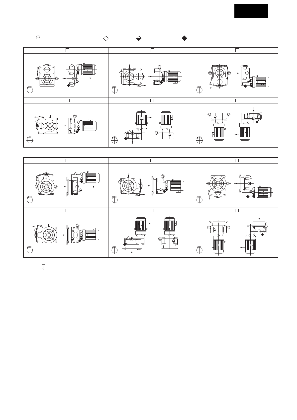
Symbol of mounting position / Position of terminal-box / Position of oil filler and draiin /
Rotation direction of output shaft (Bevel BUDDYBOX)
COMMON
Rotation direction of output shaft Oil filler plug Oil level (Oli gauge) Oil drain plug
A~
1-a Hollow shaft
Table
LH M- - 1
Up
A~
LH M- - 2
Up
A~
LH M- - 3
Up
A~
A
Table 1-b Hollow shaft
CW
A~
Ratio
19-305
CW
A~
A
Down
LV M- - 5
Up
A
Down
LHYM- -Y2
Up
A
Down
LVYM- -Y5
Up
A
Ratio
11-18
Down
364-7228
LH M- - 4
Up
A~
A
Ratio
19-305
Ratio
11-18
364-7228
Down
LHYM- -Y1
Up
A
Down
LHYM- -Y4
Up
A
Ratio
19-305
Ratio
11-18
364-7228
A~
Ratio
19-305
Ratio
11-18
364-7228
A
CCW
A~
A
Down
LV M- - 6
Up
A
Down
LHYM- -Y3
LVYM- -Y6
Up
Down
Up
Ratio
19-305
Ratio
11-18
364-7228
A~
Ratio
19-305
Ratio
11-18
364-7228
CW
A~
Down
CW
A~
Down
CW
A~
A
Down
Table 1-c Hollw shaft
LHYM- -Y2
Up
Down
LVYM- -Y5
Up
A
Down
A
CCW
A~
CW
A~
A
CW
A~
"3" Series "4" Series "5" Series
CW
A~
1. " " indicates frame size.
Note:
LHYM- -Y1
Up
Down
LHYM- -Y4
Up
Down
CW
A
A~
A
CW
A~
2. " " indicates the direction of motor lead wire.
3. The rotation direction of output shaft is case of the motor rotates "cw" looking from fan-cover side. Be careful for end of frame size with
"DA", "DB" or "DC" and with reduction ratio 11-18. Rotation direction of the output shaft is opposite from the above.
LHYM- -Y3
Up
Down
LVYM- -Y6
Up
A
Down
6
Symbol of mounting position / Position of terminal-box / Position of oil filler and draiin /
Rotation direction of output shaft (Helical BUDDYBOX)
COMMON
Rotation direction of output shaft Oil filler plug Oil level (Oli gauge) Oil drain plug
A~
Table
2-a Hollow shaft
EHYM
- -Y3
Up
Up
EHYM
- -Y2EHYM- -Y1
Up
A
CCW
A~
Down
Up
A
CCW
A~
Down
Table 2-b Hollow shaft Flange
EHYM
- -F1
Up
A
CCW
EHYM
Down
- -F4
Up
A~
CCW
A~
CCW
A~
CCW
A~
A
EVYM
EHYM
A
EVYM
A
Down
- -Y5
Up
Down
- -F2
Up
Down
- -F5
Up
CCW
A~
CCW
A~
CCW
A~
A
Down
EVYM- -Y6EHYM- -Y4
Up
Down
EHYM- -F3
Up
A
Down
EVYM- -F6
Up
A
A
A
CCW
A~
1. " " indicates frame size.
Note:
Down
CCW
A~
A
Down
CCW
A~
Down
2. " " indicates the direction of motor lead wire.
3. The rotation direction of output shaft is case of the motor rotates "cw" looking from fan-cover side. Be careful for end of frame size
with "DA", "DB" or "DC" and with reduction ratio 11-18. Rotation direction of the output shaft is opposite from the above.
7
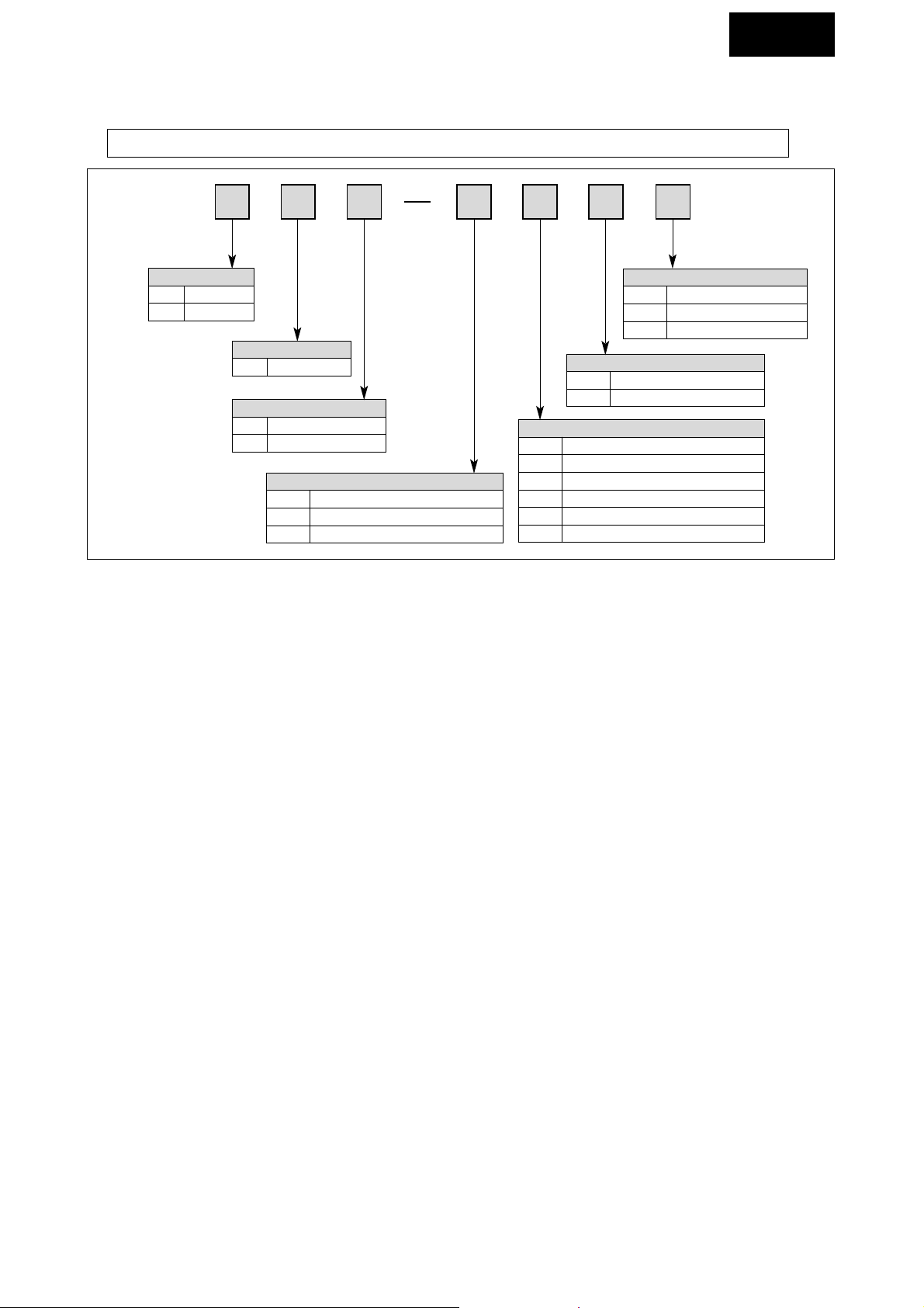
1-4) Motor Nomenclature
Nomenclature shows following information. Make sure it agrees with your order.
• Refer to related manual for units with servo motor or DC motor.
COMMON
H With Foot
Blank Flange type
HTC EX
Mounting method
T Totally enclosed
Type of casing
C Ordinary cage type
K Special cage type
Rotor
V
Blank
Inverter driven (AF Motor)
Commercial power driven
Driving power
A
Increased safety explosion-proof (Indoor)
Protection method
B
Increased safety explosion-proof (Outdoor)
C Explosion-proof (Indoor)
CX Explosion-proof (Outdoor)
X Nonexplosion-proof (Outdoor)
Blank Indoor
E Without fan (Self-cooling)
Cooling method
F With Self-ventilating fan (External fan)
B With Separate ventilation fan
E
Blank
IEC Efficiency Standards
P Premium efficiency motor
Other types of motors
Standards •Regulations
8
COMMON
Note the following on storing gearmotor or reducer, when not using the unit right away.
2-1) Storage location
Store the unit indoors in a clean dry place.
• Avoid storage outdoors or in places with humidity, dust, sudden temperature changes or corrosive gas.
2-2) Storage period
1. Do not store the unit for more than 6 months.
2. Consult us when the storing the unit for more than 6 months. Special rustproof specification is necessary.
3. Consult us when exporting the unit. Special rustproof specification in necessary.
2-3) Use after storage
1. Make sure that there are no deterioration in non-metal parts, such as oil seal and oil supply plug, before operating after
extended period of storage. Non-metal parts may deteriorate easily by the effect of ambient condition, such as
temperature and ultraviolet rays. Replace the deteriorated parts with new parts.
2. Make sure that there is no abnormal noise, vibration, or temperature rise when starting. Make sure that the brake
functions normally when for types with brake. Consult our distributor or sales office immediately if any abnormality is
found.
2. Storage
3. Transportation
DANGER
Do not stand below the unit when it is lifted. Injury or death may result.
CAUTION
Be careful not to let the unit drop or fall when moving the unit. Always use the metal hanging piece for gear or
motor with it. But do not hang the unit using the metal hanging piece after mounting with application machine.
Otherwise, it may cause personal injury or damage to the equipment and/or damage to the equipment.
Make sure of the mass of gearmotor or reducer by looking at the nameplate, packaging, drawing, catalog, etc.,
before lifting. Do not lift the gearmotor or reducer, which are heavier than the rated weight of the lifting equipment.
Otherwise, it may cause injury or damage to the equipment and lifting device.
9
COMMON
4. Installation
DANGER
Use explosion-protection type motor in explosive environment. Do not use the standard unit in explosive
environment. Otherwise, it may cause explosion, ignition, electric shock, injury, fire, or damage to the equipment.
Use the sufficient motor for explosion-protection motor matching the hazardous location (where explosive gas or
steam exists).
Inverter itself is not explosion-protection type for flameproof type motor. Always set the unit where there is no
explosive gas. Otherwise, explosion, ignition, electric shock, injury, fire, or damage of the equipment may occur.
CAUTION
Do not use gearmotor or reducer for specifications other than the one shown on the nameplate or manufacturing
specification document. Otherwise, injury or damage of the equipment may occur.
Do not place any combustible object around the gearmotor. Otherwise, fire may occur.
Do not place any object that may prevent ventilation around the gearmotor or reducer. Otherwise, it may lead to
burn or fire by abnormal temperature caused by the decreased cooling effect.
Do not step on or hang from the gearmotor and reducer. Otherwise, it may cause injury.
Do not touch the shaft end, internal keyway, or edge of motor cooling fin with bare hands. Otherwise, it may
cause injury.
Install and oil pan or other device to prevent damage for extremely oil-sensitive applications, such as food
production machine. Otherwise, it may cause defective products by oil leakage when failure occurs or at the end
of lifetime.
4-1) Place of installation
Ambient temperature: -10~40°C
Ambient humidity: 85% or less
Altitude: 1,000m or lower
Atmosphere: There should be no corrosive or explosive gas or steam.
The location should be free of dust and well-ventilated.
Location: Indoor (location free of dust without water splash)
• Consult us when operating under conditions other than the above. Special specification is necessary.
• Units made according to certain specification, such as for outdoor or for explosion protection, may be used under
specified mounting environment.
• Install the unit in location where various procedures can be carried out easily, such as inspection and maintenance.
• Install the unit to a sufficiently rigid base.
4-2) Angle of installation
Install the unit horizontally. Consult us for sloped installation.
Do not use the unit made for given slope for other slopes.
Standard shaft direction for outdoor type gearmotor is horizontal. Consult us for other shaft directions.
• Do not remove the eye-bolt on the motor. When the eye-bolt is removed for any reason, place a bolt in the tapped
hole temporarily. Waterproof treatment is necessary to prevent water entering the motor.
4-3) Under Severe Load Condition
For operation with severe vibration and frequent startup, it is recommended to tighten bolt with at least class 8.8 (by
standard JIS B-1051).
10
EHYM
EHY
Series
[Y3]
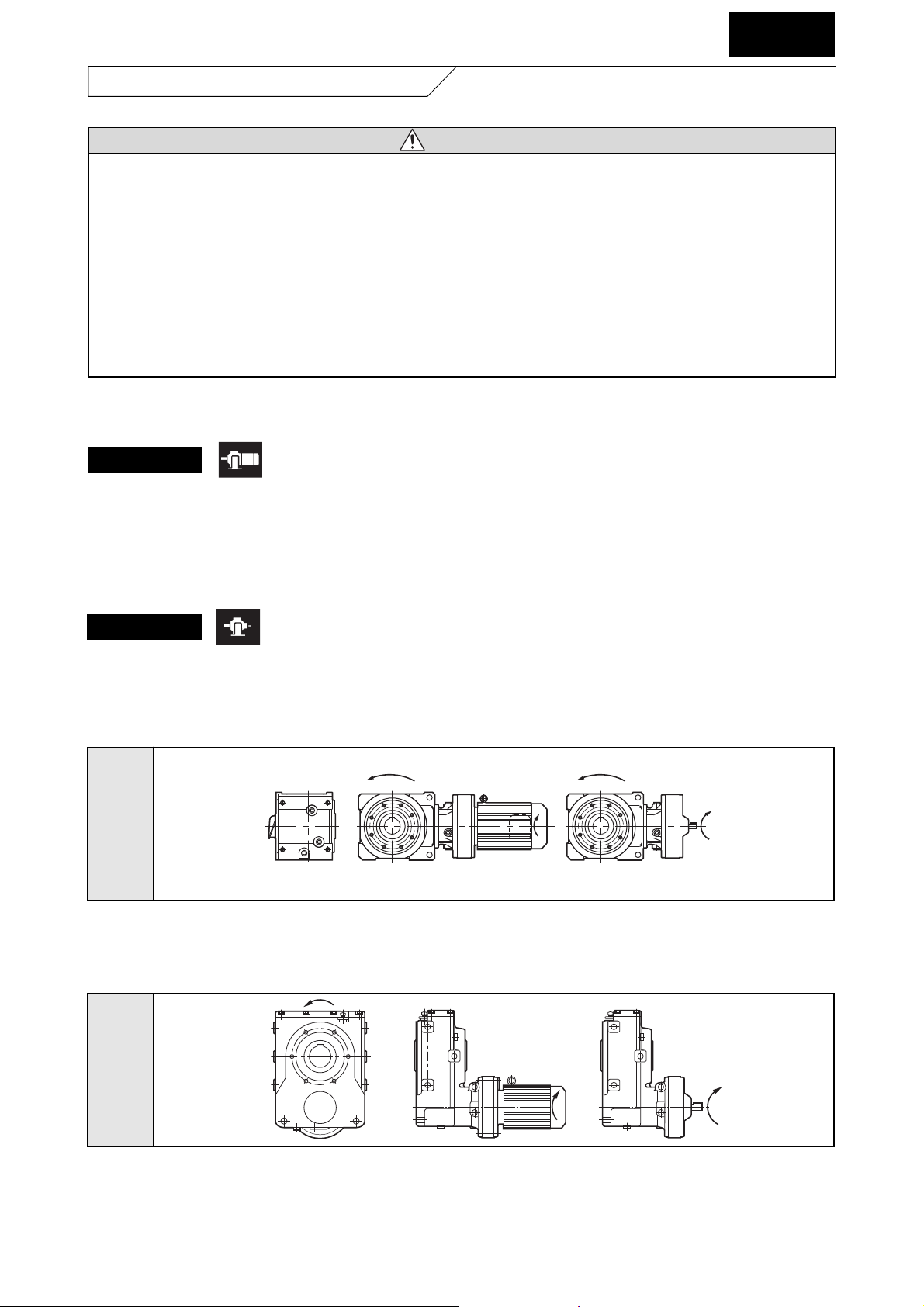
Fig. 4 Rotational Direction of Output Shaft for Helical BUDDYBOX
Relationship of rotational direction of input shaft and output shaft is as shown by the arrow in Fig. 3 and 4.
Note: • Models with reduction ratio 11 & 18 and reducers with "DA," "DB," and "DC," at the end are different from the above. Rotational direction of
output shaft is opposite from the above figure when the motor shaft and reducer type input is clockwise
• Figure above is the rotational direction for mounting style "Y1." Refer to Table 2 on page 6 or catalog for other mounting styles.
LHYM
LHY
Series
[Y1]
Fig. 3 Rotational Direction of Output Shaft for Bevel BUDDYBOX
Note: • Models with reduction ratio 11 & 18 and reducers with "DA," "DB," and "DC," at the end are different from the above. Rotational direction of
output shaft is opposite from the above figure when the motor shaft and reducer type input is clockwise
• Figure above is the rotational direction for mounting style "Y1." Refer to Table 1 on page 5 or catalog for other mounting styles.
COMMON
5. Coupling with Other Machines
CAUTION
Make sure of the rotation direction of the application machine before coupling. Difference in rotation direction may
cause injury or damage to the equipment.
Remove the temporary key on the output shaft when operating the gearmotor or reducer unit alone. Otherwise, it
may cause injury.
Place a cover to prevent touching the rotating parts. Otherwise, it may cause injury.
Be careful of the center alignment, belt tension, and parallelism of the pulleys when coupling the gearmotor or
reducer to the load. Make sure of the coupling accuracy for applications with direct connections. Adjust the belt
tension correctly for applications with belt. Make sure to tighten the bolt for pulley, and coupling before operation.
Failure to do so may result in damage of equipment or injury by broken pieces.
Gearmotor
5-1) Confirmation of direction of rotation
Fig. 3 and 4 indicates rotational direction of output shaft when wired following Fig. 25 on page 21.
• Motor shaft turns in clockwise looking from the anti-load side. This direction is as shown by the arrow in Fig. 3 and 4.
• Exchange connection R and T in Fig. 25 on page 21 with each other when rotating in the opposite direction.
Reducer
11
Fig. 6
Fig. 7
COMMON
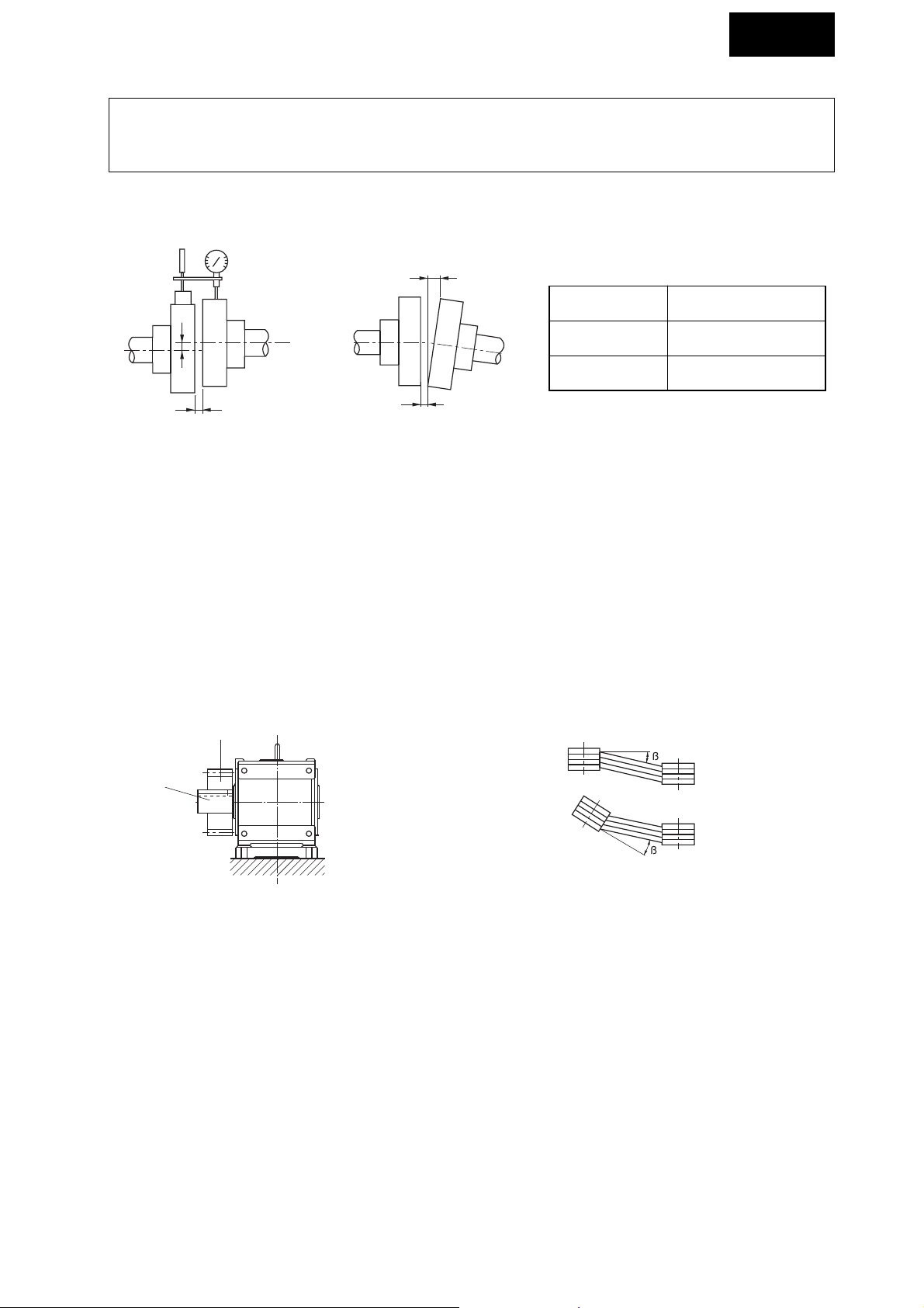
5-2) Installation of coupling
• Do not apply shock or excess axial load to the shaft when attaching the coupling. It may cause bearing damage or collar
may fall off.
• We recommend attachment by shrink fitting.
(1) When Using Coupling
Adjust the dimensions in Fig. 5 (A, B, and X) within the tolerance shown in Table 3.
(2) When Using with Chain Sprocket and Gear
• Make the tension angle of the chain perpendicular to the shaft.
• Refer to your catalog and other materials on chain for correct tension.
• Use sprocket and gears with pitch diameter at least three times of shaft diameter.
• Make the load point of sprocket and gear closer than the shaft center to the gearmotor or reducer side
(Refer to Fig. 6).
(3) When Using with V-belt
• Too much tension on v-belt will damage the shaft and bearing. Refer to your catalog and other materials on v-belt
for correct tension.
• Make the parallelism and eccentricity (b) between two pulleys 20' or smaller (Refer to Fig. 7.)
• Use the matched set with same circumferential length when using multiple v-belts.
Tolerance for A
dimension
0.1mm or maker’s
specification
Tolerance for B
dimension
0.1mm or maker’s
specification
X dimension Maker’s specification
Table 3
Centering Accuracy of Flexible Coupling
Fig. 5
B
A
X
X
Shaft
Gear
12
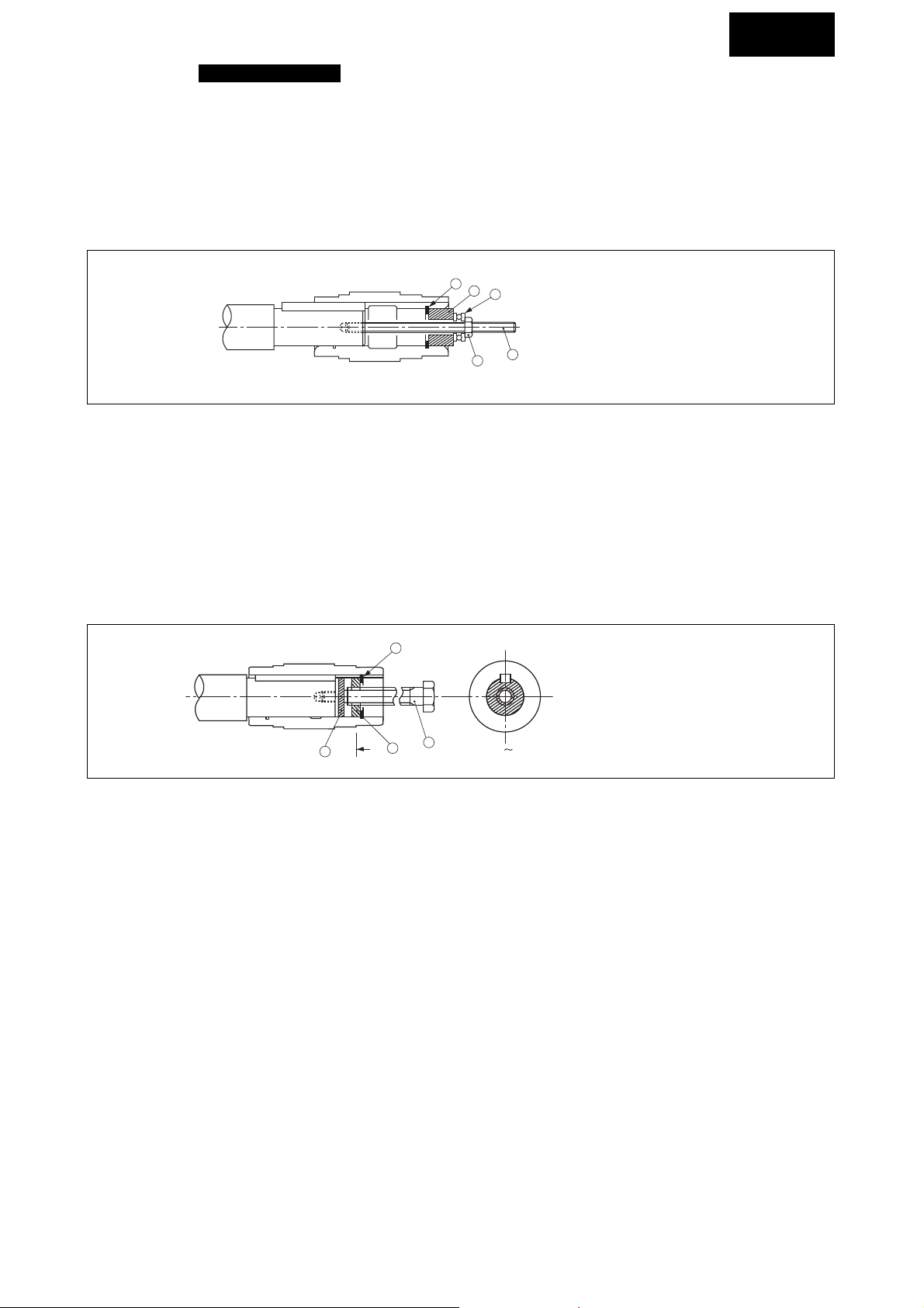
5-3) Coupling hollow shaft type with other machines
(1) Attachment and Removal of Hollow shaft and Driven Shaft
(a) Attachment to Driven Shaft
Apply molybdenum disulfide grease to the surface of driven shaft and inner diameter of hollow shaft. Insert the
gearmotor or reducer to driven shaft.
Pound the end surface of hollow shaft lightly with a wooden hammer when the fitting is tight.
Do not pound casing and oil seal for this purpose. Jigs as shown in Fig. 8 can help smooth insertion when the fitting is
especially tight.
(a) .......... Retaining ring
(b) .......... Spacer
(c) .......... Thrust bearing
(d) .......... Nut
(e) .......... Bolt
Fig.8 Coupling jig
Hollow shaft conforms to JIS H8.
Make the fitting between hollow shaft and driven shaft when there is shock load or when the radial load is large. (js6 or
k6 of JIS standard is recommended for driven shaft.)
(b) Uncoupling from driven shaft
Make sure there is no excess force between casing and hollow shaft. Jig as shown in Fig. 9 can help smooth removal.
Prepare jig and parts for attachment, fixing, and removal by yourself.
(f) ............Spacer
(g) .......... Upper bolt
(h) .......... Disc
(i) ........... Retaining ring
Fig.9 Uncoupling jig
COMMON
a
b
c
e
d
i
g
f
h
A
A
13
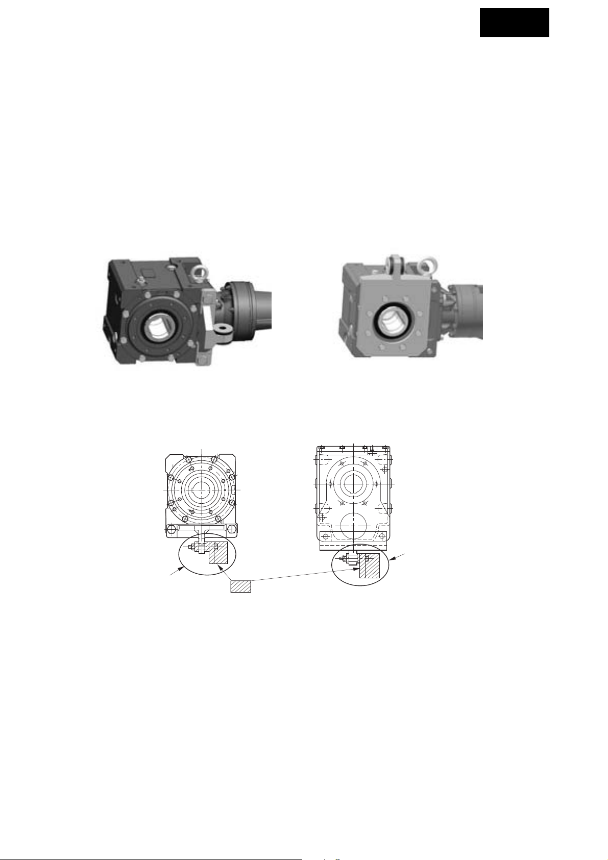
(2) How to attach of torque arm (option)
Attention of attachment
1 Attach torque arm to the application machine side of the reducer.
2 Attach retainer parts of torque arm (refer Fig.11) to release extra force between the reducer and the driven shaft.
(Retainer is to be supplied by customer.)
3 Never lock the torque arm completely with locking bolts and such.
4 Attach shock-absorbing material between torque arm and attachment bolt (or spacer).
5 Use bolt which meets JIS standard of screw strength ranking by 10.9 or above.
6 Bolts must be made to lock when a torque arm is used. (The method to lock is to use U-nut or spring washer, or to
supply adhesive for locking screw, etc.)
Note: As shock-absorbing material, rubber bushes and spring washers are prepared.
By use and operating condition, different shock-absorbing materials are recommended.
• In the case of one direction operation : Spring washers or rubber bushes
• In the case of start-stop operation : Spring washers
Attachment type torque arm (option) Banjo type torque arm (option)
Fig.10 Example of using torque arm
Fig.11 Example of retainer (for attachment type torque arm)
COMMON
Retainer parts of torque arm
Retainer parts of torque arm
Part of is to be supplied by customer.
 Loading...