

Sumitomo Hyponic 1220, Hyponic 1230, Hyponic 1330, Hyponic 1340, Hyponic 1420 Operating And Maintenance Manual
...
Operating and Maintenance Manual
Hyponic®
07.020.60.002
Hyponic O&M 2019

Contents
Safety Precautions
Safety Precautions . . . . . . . . . . . . . . . . . . . . . . . . . . . . . . . . . . . . . . . . . . . . . . . . . . . . . . . . . . . . . . . . . 1
Inspection Upon Delivery . . . . . . . . . . . . . . . . . . . . . . . . . . . . . . . . . . . . . . . . . . . . . . . . . . . . . . . . . . 2
Lubrication . . . . . . . . . . . . . . . . . . . . . . . . . . . . . . . . . . . . . . . . . . . . . . . . . . . . . . . . . . . . . . . . . . . 2
Storage . . . . . . . . . . . . . . . . . . . . . . . . . . . . . . . . . . . . . . . . . . . . . . . . . . . . . . . . . . . . . . . . . . . . . . . . . . . 3
Transportation. . . . . . . . . . . . . . . . . . . . . . . . . . . . . . . . . . . . . . . . . . . . . . . . . . . . . . . . . . . . . . . . . . . . . 4
Installation . . . . . . . . . . . . . . . . . . . . . . . . . . . . . . . . . . . . . . . . . . . . . . . . . . . . . . . . . . . . . . . . . . . . . . . . 4
Standard Operating Conditions . . . . . . . . . . . . . . . . . . . . . . . . . . . . . . . . . . . . . . . . . . . . . . . . 4
Mounting Angle . . . . . . . . . . . . . . . . . . . . . . . . . . . . . . . . . . . . . . . . . . . . . . . . . . . . . . . . . . . . . . 4
Motor Mounting (Quill Shaft Type) . . . . . . . . . . . . . . . . . . . . . . . . . . . . . . . . . . . . . . . . . . . . . 4
Direction of Rotation . . . . . . . . . . . . . . . . . . . . . . . . . . . . . . . . . . . . . . . . . . . . . . . . . . . . . . . . . . 5
Connecting to the Driven Machine . . . . . . . . . . . . . . . . . . . . . . . . . . . . . . . . . . . . . . . . . . . . . 6
Flange or Foot Mount. . . . . . . . . . . . . . . . . . . . . . . . . . . . . . . . . . . . . . . . . . . . . . . . . . . . . 6
Solid Shaft Type . . . . . . . . . . . . . . . . . . . . . . . . . . . . . . . . . . . . . . . . . . . . . . . . . . . . . . . . . . 6
• Carefully read this maintenance manual and all accompanying documents before use (installation, operation,
maintenance, inspection, etc.). Thoroughly understand the machine, information about safety, and all precautions
for correct operation. Retain this manual for future reference.
• Pay close attention to the “DANGER” and “CAUTION” warnings regarding safety and proper use.
DANGER
Improper handling may result in physical damage, serious personal injury and/or death.
CAUTION
Improper handling may result in physical damage and/or personal injury.
Matters described in CAUTION may lead to serious danger depending on the situation.
Be sure to observe important matters described herein.
Precautions for Mounting Hollow Shaft Type . . . . . . . . . . . . . . . . . . . . . . . . . . . . . . . 8
Hollow Shaft Type . . . . . . . . . . . . . . . . . . . . . . . . . . . . . . . . . . . . . . . . . . . . . . . . . . . . . . . . 8
Keyed Hollow Bore . . . . . . . . . . . . . . . . . . . . . . . . . . . . . . . . . . . . . . . . . . . . . . . . . . 8
Shrink Disc . . . . . . . . . . . . . . . . . . . . . . . . . . . . . . . . . . . . . . . . . . . . . . . . . . . . . . . . . 11
Torque Arm Installation . . . . . . . . . . . . . . . . . . . . . . . . . . . . . . . . . . . . . . . . . . . . . . . . . 13
Wiring . . . . . . . . . . . . . . . . . . . . . . . . . . . . . . . . . . . . . . . . . . . . . . . . . . . . . . . . . . . . . . . . . . . . . . . . . . . 15
Wiring Connections for Standard Motor Contactor . . . . . . . . . . . . . . . . . . . . . . . . . . . . . . . . . . 15
Wiring Connections for VFD (Inverter) . . . . . . . . . . . . . . . . . . . . . . . . . . . . . . . . . . . . . . . . . . . . . . 16
Operation . . . . . . . . . . . . . . . . . . . . . . . . . . . . . . . . . . . . . . . . . . . . . . . . . . . . . . . . . . . . . . . . . . . . . . . . 18
Daily Inspection and Maintenance . . . . . . . . . . . . . . . . . . . . . . . . . . . . . . . . . . . . . . . . . . . . . . . . . 19
FB Brake Assembly – Inspection, Adjustment, and Maintenance . . . . . . . . . . . . . . . . . . . . . 20
Brake Models FB-01A1, FB-02A1, and FB-05A1. . . . . . . . . . . . . . . . . . . . . . . . . . . . . . . . . . . . . . . . 20
Brake Models FB-1D, FB-2D, FB-1E, FB-1HE, FB-2E and FB-3E . . . . . . . . . . . . . . . . . . . . . . . . . 23
• Transport, installation, plumbing, wiring, operation, maintenance, and inspections should be performed by trained
technicians; otherwise, electric shock, personal injury, fire, or damage to the equipment may result.
• In the case of disassembly, assembly or overhaul of this device, contact the nearest authorized service station.
• When using the equipment in conjunction with an explosion proof motor, a technician with electrical expertise
should supervise the transport, installation, plumbing, wiring, operation, maintenance and inspection of the
equipment; otherwise, explosion, ignition, electrical shock, personal injury, fire or damage to the equipment may
result.
• When the unit is to be used in a system for human transport, a protecting device for human safety should be
installed to prevent chances of accidents resulting in personal injury, death, or damage to the equipment due to
running out of control or falling.
• When the unit is to be used for an elevator or lifter, install a safety protecting device on the elevator side to prevent
it from falling; otherwise, personal injury, death, or damage to the equipment may result.
Brake Models FB-5E, FB-8E, FB-10E, and FB-15E . . . . . . . . . . . . . . . . . . . . . . . . . . . . . . . . . . . . . 27
Troubleshooting . . . . . . . . . . . . . . . . . . . . . . . . . . . . . . . . . . . . . . . . . . . . . . . . . . . . . . . . . . . . . . . . . . 32
Hyponic® Operating and Maintenance Manual
www.SumitomoDrive.com
Hyponic® Operating and Maintenance Manual 1
Inspection Upon Delivery Storage
• Unpack the unit after verifying that it is positioned right side up; otherwise, injury may result.
• Verify that the unit received is in fact the one you ordered. Installing the wrong unit may result in
personal injury or equipment damage.
• Do not remove the nameplate.
Verify the items listed below upon receiving the product. If a nonconformity or problem is found, please
contact your nearest agent, distributor, or sales office.
1. Does the information on the nameplate conform to what you ordered?
2. Was any part broken during transport?
3. Are all bolts and nuts tightened firmly?
4. Were the ordered accessories received?
Lubrication
Hyponic® units are grease-lubricated. They are filled prior to shipment and arrive ready for customer use. It is recommended to overhaul the gearbox after 20,000 hours.
Note: Over-hauling consists of disassembling the unit, replacing the seals and gaskets, cleaning the internal parts and
then repacking the unit with designated grease.
If this product is not for immediate use, please note the following points when storing it.
Storage Location
Store the product indoors in a clean, dry location.
Do not store outdoors. Store in a location that is free of moisture, dust, extreme temperature changes,
corrosive gases, etc.
Storage Time
• The storage time should be within one year.
• If the storage time exceeds one year, adherence to special rust prevention specifications is required. Please consult
with us.
• If for export, adherence to export rust prevention specifications is required. Please consult with us.
Standard Rust Prevention Specifications
Standard Low Temperature Food Grade
Nihon Koyu BA-11A Nihon Koyu BH-17B Fuchs Cassida SGG 000
Table 1. Grease Lubrication Levels.
Size Ratio oz. (g)
1120 5 - 60 3.17 (90)
1220 5 - 60 5.64 (160)
1230 80 - 240 7.05 (200)
1320 5 - 60 9.17 (260)
1330 80 - 240 10.9 (310)
1340 300 - 1440 16.2 (460)
1420 5 - 60 19.8 (560)
1430 80 - 240 26.5 (750)
1440 300 - 1440 31.7 (900)
Size Ratio oz. (g)
1530 80 - 240 52.9 (1500)
1531 40 - 80 52.9 (1500)
1540 300 - 1440 52.9 (1500)
1630 80 - 120 68.8 (1950)
1631 150 - 240 68.8 (1950)
1632 30 74.1 (2100)
1632 40 - 60 68.8 (1950)
1633 20 - 25 74.1 (2100)
1633 30 - 40 68.8 (1950)
External Rust Prevention:
Rust prevention oil is applied when shipping from the factory. Check rust conditions every six months after
shipment. Reapply the rust prevention process, if necessary.
Internal Rust Prevention:
Store in an ordinary factory or warehouse in an environment free of moisture, dust, extreme temperature
changes, corrosive gases, etc.
Using After Storage
• Oil seals are affected by temperature, ultraviolet light, and other ambient conditions and can easily degrade. After
long storage periods, inspect before operation, and replace any degraded seals with new seals.
• At startup, check that there are no unusual noises, vibrations, temperature rises, or other symptoms. For motor with
brakes, check that brakes work properly. If any abnormalities are found, immediately contact the nearest authorized
service station.
1520 5 - 60 31.7 (900)
1521 5 - 25 31.7 (900)
1522 5 - 15 31.7 (900)
2 Hyponic® Operating and Maintenance Manual
1634 5 - 15 106 (3000)
1634 20 - 25 68.8 (1950)
1640 300 - 1440 127 (3600)
www.SumitomoDrive.com
Hyponic® Operating and Maintenance Manual 3
Transportation
Do not stand directly under a unit suspended by a crane or other lifting mechanism; otherwise, injury or
death may result.
• Exercise ample care so as not to drop the unit.
When a hanging bolt or hole is provided, be sure to use it. After mounting a unit to a machine, do not hoist the
entire machine using the hanging bolt or hole; otherwise, personal injury or damage to the equipment and/or
lifting device may result.
• Before hoisting, refer to the rating plate, crate, outline drawing, catalog, etc. for the weight of the unit. Never hoist
a unit that exceeds the rating of the crane or other mechanism being used to lift it; otherwise, personal injury or
damage to the equipment and/or lifting device may result.
• Use an appropriate hanging bolt or hole, and make sure that the eye-bolt and/or nut is not loose before hoisting.
• Bolt the motor into place. Refer to the motor operating instructions for proper bolt tightening torque. Important: If
the bolt is tightened when the fitting is not inserted, uneven tightening will result, causing damage to the internal
bearing and other components.
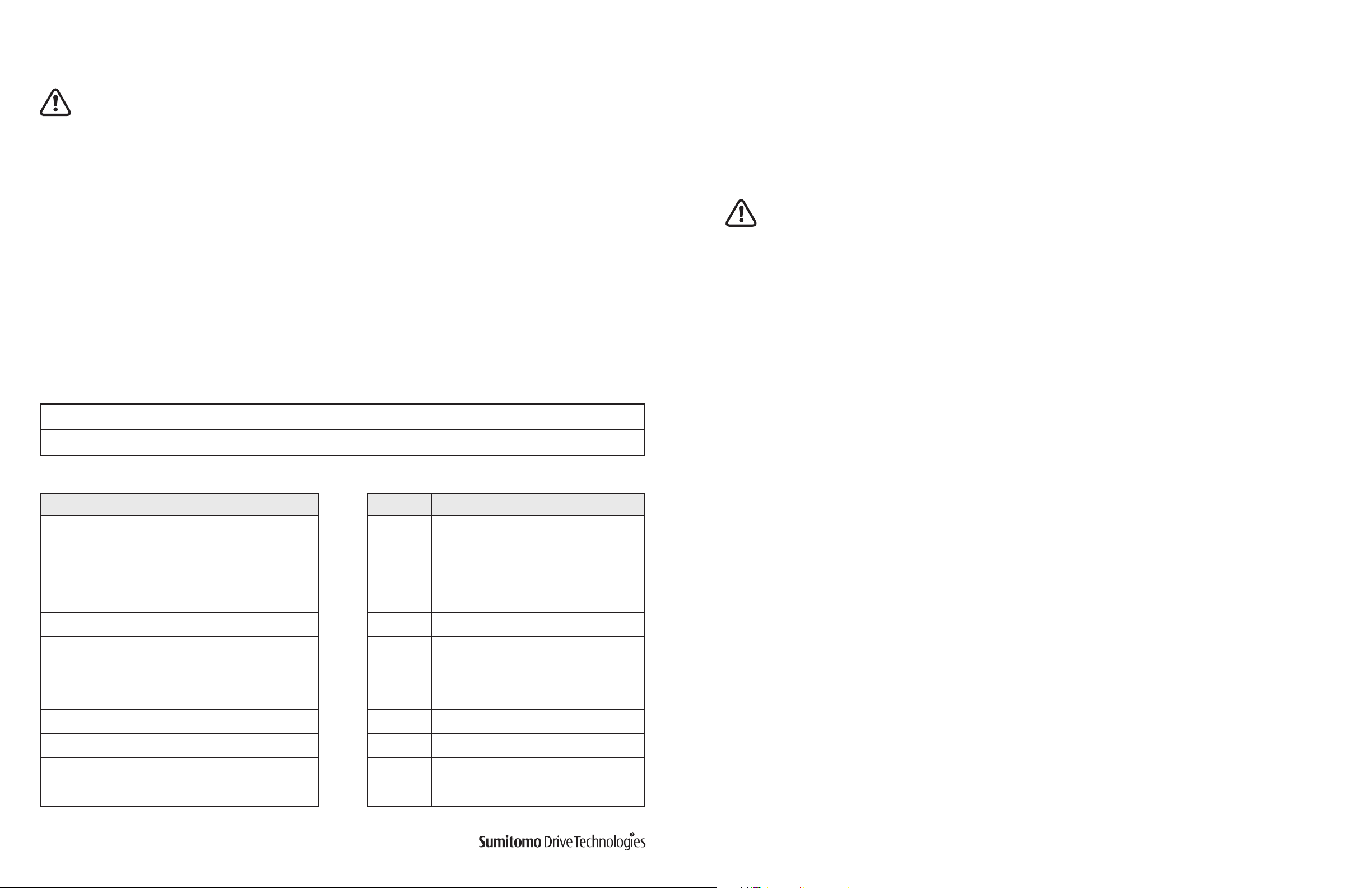
Direction of Rotation
• After wiring the motor as recommended in the Wiring section, the motor shaft rotates to the right as seen from
the fan cover side. Figure 1 shows the direction of rotation for the output shaft depending on the size and ratio
combination.
• After corroborating direction of rotation, the gearmotor can be connected to the driven machine. It is
recommended to do a test run with no load, and increase load gradually. Observe precautions listed in Table 8 Trial
Run Precautions in the Operation section during test run.
Fig. 1 Rotating Direction of the Output Shaft
Installation
Standard Operating Conditions
Ambient temperature:
Humidity:
Altitude:
Atmosphere:
Mounting Angle
There is no limit on a mounting angle.
Do not remove the motor’s eye-bolt. In the rare case that it is removed, insert a bolt or other appropriate material
into the screw hole to prevent water or other substances from entering the motor through the screw hole.
Motor Mounting (Quill Input Shaft)
Reducer Supplied with Motor (assembled):
Some units may come from the factory with the motor attached. In this case, no additional preparation is required.
Customer Supplied Motor or Motor Supplied Separately (disassembled):
• Inspect the input shaft hollow bore and the motor shaft for debris or other material that may prevent the insertion
of the motor shaft into the hollow quill input shaft – carefully clean if necessary.
• To enable easy installation and removal of the motor, apply anti-seize paste to both the reducer hollow bore and the
motor shaft.
• Hollow input shaft units for the Food and Beverage Industry have either an o-ring or gasket material (solid or
liquid) for installation between the motor and reducer.
• Place the motor key into the motor shaft and carefully insert the motor into the quill high-speed shaft of the
reducer. Do not force the assembly if the shafts are slanted or misaligned or if the key is only partially engaged.
• Ensure that the motor flange bolts are aligned with the through holes of the reducer flange, and also ensure that the
motor is properly aligned with the reducer.
14°F to 104°F (-10°C to 40°C)
85% or less
Lower than 3300 ft (1000 m) above sea level
Free from corrosive gases, explosive gases or steam. It should also be free from dust and well
ventilated.
CCW
CW
Model
1120 5, 7, 10, 12, 15, 20, 25, 30, 40, 50, 60 1120 –
1220 5, 7, 10, 12, 15, 20, 25, 30, 40, 50, 60 1220 –
1230 – 1230 80, 100, 120, 150, 200, 240
1320 5, 7, 10, 12, 15, 20, 25, 30, 40, 50, 60 1320 –
1330 – 1330 80, 100, 120, 150, 200, 240
1340 300, 360, 480, 600, 720, 900, 1200, 1440 1340 –
1420 5, 7, 10, 12, 15, 20, 25, 30, 40, 50, 60 1420 –
1430 – 1430 80, 100, 120, 150, 200, 240
1440 300, 360, 480, 600, 720, 900, 1200, 1440 1440 –
1520 5, 7, 10, 12, 15, 20, 25, 30, 40, 50, 60 1520 –
1521 5, 7, 10, 12, 15, 20, 25 1521 –
1522 5, 7, 10, 12, 15 1522 –
1530 – 1530 80, 100, 120, 150, 200, 240
1531 – 1531 40, 50, 60, 80
1540 300, 360, 480, 600, 720, 900, 1200, 1440 1540 –
1630 10, 12, 15, 20, 25, 30, 40, 50 1630 60, 80, 100, 120
1631 – 1631 150, 200, 240
1632 10, 12, 15, 20, 25, 30 1632 40, 50, 60
1633 20, 25 1633 30, 40
1634 5, 7, 10, 12, 15 1634 20, 25
1640 300, 360, 480, 600, 720, 900, 1200, 1440 1640 –
Note: Swapping two of the three input power leads of a three-phase induction motor will cause the motor direction to reverse.
Counter Clockwise Reduction Ratio (:1)
CW
CW
Model Clockwise Reduction Ratio (:1)
4 Hyponic® Operating and Maintenance Manual
www.SumitomoDrive.com
Hyponic® Operating and Maintenance Manual 5
Connecting to the Driven Machine
Flange or Foot Mount
Excessively loose chains will cause a jolt upon start-up that may damage the Hyponic® unit and the driven
machine. Excessive tension of V-belts or chain may cause bearing failure.
1. Mount the gearmotor on a rigid surface.
2. Ensure there is no restriction for mounting angle.
3. Use hexagon socket head bolts when mounting RNF series (flange-mount type). See Table 2 for bolt sizes.
Table 2. Flange Mount Bolt Size.
Series Frame Size Type Bolt Size
RNFJ(M)
RNFX(M)
RNFM
1120
1220, 1230 M8
1320, 1330, 1340 M10
1420, 1430, 1440
1520, 1521, 1522
1530, 1540 M16
1630, 1631,
1632,1633, 1640
Through Hole
M6
M12
M20
Fig. 2
Fig. 3
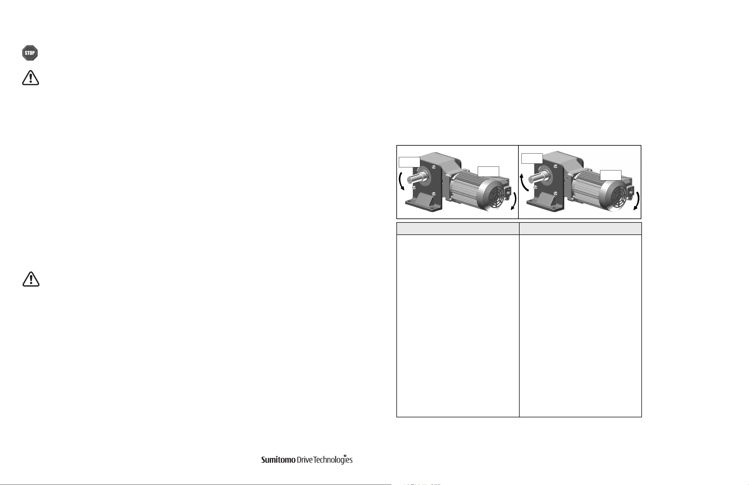
Solid Shaft Type
When mounting connected equipment, do not apply impact or excessive axial or radial load to the shaft. The
bearing could be damaged, or the collar could come off.
1. Mount the connecting device, such as a coupling, chain, sprocket, gear or V-pulley, on the shaft as close as possible
to the shaft collar as shown in Figure 2. This places the load point between the center of the shaft and the shaft
collar.
2. We recommend using end cap screws or interference fit on the connecting device to avoid possible bearing
damage from excessive force or thrust load that may be applied to the shaft while fitting the connecting device
(Figure 3).
3. When connecting the Hyponic® unit to the driven machine with:
a. V belts, keep parallelism and eccentricity β if the pulleys within 20’ as shown on Figure 4.
b. Couplings, align according to the coupling manufacturer’s recommendation.
c. Chains, sprockets or gears, select a pitch circle diameter at least 3 times the shaft diameter. For chain tension,
please refer to the chain manufacturer recommendation and keep tension angle perpendicular to the shaft.
Fig. 4
6 Hyponic® Operating and Maintenance Manual
www.SumitomoDrive.com
Hyponic® Operating and Maintenance Manual 7
Hollow Shaft Type
Precautions for Mounting the Hollow Shaft Type
1) Driven Shaft Size
• If the driven shaft dimension is small and there is a space from the hollow shaft, abrasion from fretting tends to
occur. The resulting abrasion powder may get pinched in the oil seal, causing the grease to leak.
• Furthermore, vibrations due to the space may damage the parts inside the drive.
• If the driven shaft length is short, excessive force is applied on the hollow shaft, possibly causing vibration or
grease leak.
• If the effective length of driven shaft is short, the key and the keyway may be damaged.
2) Mounting on the Driven Shaft
• If the hollow shaft end face is hit with a metal hammer or the driven shaft was biting on the hollow shaft when
assembled, the hollow shaft may become deformed and the oil seal contact may become uneven, causing the
grease to leak.
• If the case or the oil seal is hit, the damaged or deformed case or oil seal may cause the grease to leak.
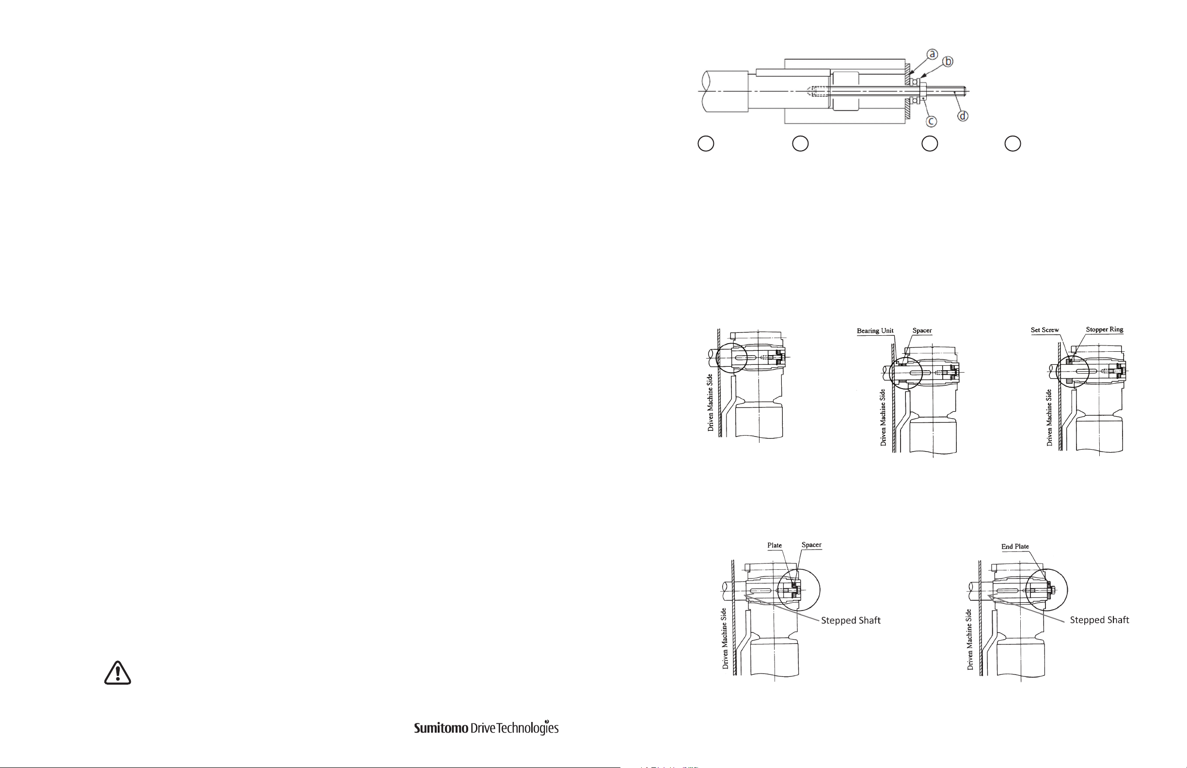
Fig. 5
......Spacer ......Thrust Bearing ......Nut ......Double end threaded bolt
a
The hollow shaft is made according to ISO H8 tolerances. Following installation, ensure that the fitting
between the hollow and the driven shaft is tightened correctly. We recommend ISO js6 or k6 as the
tolerance for the driven shaft.
b. Mounting the Hyponic® unit
Be sure to fix the gearmotor onto the driven shaft. Fixing options are shown on Figures 6 and 7.
Fig. 6: Method of fixing in which the product does not move to the machine side.
b
c
d
3) Fixing on the Driven Shaft
• If the hollow shaft is not fixed, it may vibrate in the thrust direction due to the vibration from the operation or
from the machine side, possibly causing the oil seal performance to become uneven and the grease to leak.
• The vibration may also damage the parts inside the drive.
4) Torque Arm Retainer
• Fixing the torque arm retainer may prevent the case from following the driven shaft movement, and as a result of
excessive force being applied on the hollow shaft, the grease may leak through the oil seal.
• It may also damage the parts inside the drive.
When using the hollow shaft type, be sure to refer to the mounting procedure on pages 8 to 14.
Keyed Hollow Bore
1. Mount the gearmotor onto the driven shaft that has sufficient rigidity.
2. Ensure there is no restriction for the mounting angle.
3. Mounting Procedures:
a. Connecting a Driven Shaft
Stepped Shaft Option Spacer Option Set Screw Option
Fig. 7: Method of fixing in which the product does not move in the opposite direction of the
machine.
Spacer and Plate Option End Plate Option
Apply customer-supplied anti-seize grease to the surface of the driven shaft and the inner surface of the
hollow shaft. Slide the Hyponic® unit onto the driven shaft. To make the installation smoother if the fit
is too tight, lightly tap the end of the hollow output shaft with a wooden hammer. Avoid hitting the
casing. To ensure smooth installation of the drive, we recommend the use of a jig shown in Figure. 5.
Inappropriate installation will result in shaft fretting. Fretting will cause shaft wear, jamming,
and misalignment between the gearmotor and driven shaft.
8 Hyponic® Operating and Maintenance Manual
www.SumitomoDrive.com
Hyponic® Operating and Maintenance Manual 9
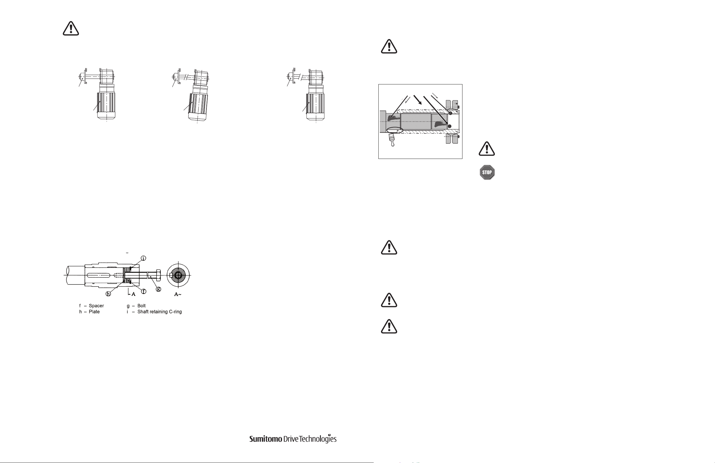
Fig. 8
Hyponic® hollo
shaft model
Hyponic® hollo
shaft model
Hyponic® hollo
shaft model
When installing the gearmotor when flange-mounted, ensure that the gearmotor and the
shaft of the driven machine are properly aligned so that the gearmotor is free from excessive
force (Figure 8).
Shrink Disc
Before placing unit onto driven shaft, do not apply grease, oil, or anti-seize grease to the entire driven
shaft or to the bore of the shrink disc. Use of these friction-minimizing products will adversely affect the
ability of the unit to transmit torque.
Bearing unit
w
Correct
d. Removing the Shaft
Do not apply excessive force to the unit and shaft. Using a jig as shown in Figure 9 will facilitate
removal of the shaft.
Fig. 9
Bearing unit
w
Incorrect
Poor perpendicularity of driven shaft
center and mounting flange surface
Bearing unit
w
Incorrect
Poor concentricity of driven
shaft and mounting flange
Degrease these areas
1
Clean and degrease contact surfaces; reducer shaft and bore, and the machine
driven shaft.
Apply Molykote 321 or an equivalent dry film lubricant to the driven shaft
projection opposite from the shrink disc.
Apply Molykote 321
to this shaft area only
For food grade application, use food grade dry film lubricant.
Do not apply any friction minimizing compound to the driven shaft at
or near the shrink disc
2
Align the driven shaft with the reducer hollow bore and carefully slide unit onto the driven shaft.
If the fit is tight, strike on the reducer hollow bore with a mallet to assist in the assembly.
If using a soft non-metallic mallet during installation, strike only against the unit’s steel hollow bore. Do not
strike the reducer housing or oil seal. Damage to the bearings, the housing, and/or the seals may occur.
Note: Customer should supply parts for setting, securing or removing the shaft.
10 Hyponic® Operating and Maintenance Manual
Note: If the fit is tight, use a jig such as the one shown in Figure 5 to ease assembly. Sumitomo does not supply a
mounting jig. This information is provided for reference only.
Never tighten locking screws before shaft installation. Inner ring may become permanently contracted even
at low tightening torques.
Ensure that all power switches are locked out before installing or removing shrink disc. Wear safety glasses
and protective clothing at all times
3
Remove any wooden spacers that may have been used during shipping. Lightly lubricate the hub outside diameter
and shrink disc bore.
www.SumitomoDrive.com
Hyponic® Operating and Maintenance Manual 11
 Loading...