

Sumitomo FINE CYCLO FC-A 15 G, FINE CYCLO FC-A 25 G, FINE CYCLO FC-A 45 G, FINE CYCLO FC-A 65 G, FINE CYCLO FC-A 35 G Operating Manual [de, en]
...Page 1

Betriebsanleitung
Operating Manual
FINE CYCLO
Präzisionsgetriebe
Precision Gears
Nr.
01/05
991051
Page 2

FC_D_01_05 Nr. 991051 Ausgabe: 01/05 Seite 1
Copyright 2005 Alle Rechte vorbehalten
Nachdruck, auch auszugsweise, ist nur mit ausdrücklicher
Genehmigung von Sumitomo Drive Technologies gestattet.
Die Angaben in dieser Einbau- und Betriebsanleitung wurden mit grösster Sorgfalt auf ihre Richtigkeit geprüft.
Trotzdem kann für eventuelle fehlerhafte oder unvollständige Angaben keine Haftung übernommen werden.
Technische Änderungen vorbehalten.
Inhaltsverzeichnis:
1. Allgemeine Hinweise . . . . . . . . . . . . . . . . . . . . . . . . . . . . .2
2. Hinweise zur Sicherheit . . . . . . . . . . . . . . . . . . . . . . . . . . .2
3. Hinweise zum Transport . . . . . . . . . . . . . . . . . . . . . . . . . .2
4. Anbau von Übertragungselementen . . . . . . . . . . . . . . . . .3
5. Einbau des Getriebes/Getriebemotors . . . . . . . . . . . . . . .3
5.1 Notwendige Hilfsmittel . . . . . . . . . . . . . . . . . . . . . . . . . . . . . .3
5.2 Einbautoleranzen am Getriebe/Getriebemotor . . . . . . . . . . . . . .3
5.3 Prüfungen vor Beginn der Installationsarbeiten . . . . . . . . . . . . .3
5.4 Vorbereitende Arbeiten . . . . . . . . . . . . . . . . . . . . . . . . . . . . . .3
5.5 Aufstellung . . . . . . . . . . . . . . . . . . . . . . . . . . . . . . . . . . . . . .3
6. Sicherheitsmaßnahmen . . . . . . . . . . . . . . . . . . . . . . . . . .3
6.1 Einbausatz nicht zerlegen . . . . . . . . . . . . . . . . . . . . . . . . . . . . . . .3
6.2 Vor Verunreinigung schützen . . . . . . . . . . . . . . . . . . . . . . . . . .3
6.3 Einzelteile nicht austauschbar
. . . . . . . . . . . . . . . . . . . . . . . . .
3
6.4 Exakte Montage . . . . . . . . . . . . . . . . . . . . . . . . . . . . . . . . . . . . . .4
6.5 Anzugsmomente
. . . . . . . . . . . . . . . . . . . . . . . . . . . . . . . . . .
4
6.6 Sicherheitshinweise zum Einsatz im Ex-Bereich . . . . . . . . . . . . . .4
6.7 Sicherheitshinweise zum Betrieb mit Motor/Frequenzumrichter . . .5
7. Check-Liste für ATEX zugelassene Getriebe
. . . . . . . . . . . . .5
8. Funktionsstörungen . . . . . . . . . . . . . . . . . . . . . . . . . . . . . .5
9. Type FC-A . . . . . . . . . . . . . . . . . . . . . . . . . . . . . . . . . . . . . .6
10. Type F1C-A . . . . . . . . . . . . . . . . . . . . . . . . . . . . . . . . . . . . .9
11. Type F2C-A . . . . . . . . . . . . . . . . . . . . . . . . . . . . . . . . . . . .11
12. Type F3C-A . . . . . . . . . . . . . . . . . . . . . . . . . . . . . . . . . . . .13
13. Type F2C-T . . . . . . . . . . . . . . . . . . . . . . . . . . . . . . . . . . . .14
FINE CYCLO Betriebsanleitung
Page 3

FINE CYCLO Betriebsanleitung
FC_D_01_05 Nr. 991051 Ausgabe: 01/05 Seite 2
Gefahr
Eine falsche Anwendung der Maschine kann zu Körperschäden, ernsthaften Verletzungen und/ oder
lebensgefährlichen Situationen führen.
Schädliche Situation
Schäden am Antrieb oder der Umgebung können die Folge sein.
Gefährliche Situation
Leichte Verletzungen können die Folge sein.
1. Allgemeine Hinweise
Bitte beachten Sie in dieser Dokumentation unbedingt die folgenden Sicherheitshinweise!
Hilfreiche Informationen
Entsorgung
Bitte achten Sie auf die geltenden Bestimmungen
Lesen Sie vor der Arbeit mit der Maschine (Montage, Betrieb, Wartung, Inspektion, usw.) diese
Betriebsanleitung aufmerksam durch, so dass Sie eine genaue Kenntnis über die richtige Bedienung der
Fine Cyclo Einbausätze, die anzuwendenden Sicherheitsbestimmungen und die zu beachtenden
Warnhinweise haben. Bewahren Sie diese Anleitung bei der Maschine auf, so dass Sie bei Bedarf jederzeit nachschlagen können.
Transport, Montage, Schmierung, Betrieb, W artung und Inspektion dürfen nur durch ausgebildetes technisches Fachpersonal durchgeführt werden; andernfalls besteht die Gefahr von Verletzungen oder
Schäden an der Maschine.
Niemals in sich bewegende Teile fassen und Fremdkörper von diesen Teilen fernhalten; andernfalls
besteht die Gefahr von Verletzungen oder Schäden an der Maschine.
Die Anlage darf nur für den vorgesehenen Verwendungszweck eingesetzt werden; andernfalls besteht
die Gefahr von Verletzungen oder Schäden an der Maschine.
2. Hinweise zur Sicherheit
3. Hinweise zum Transport
Bei Getrieben mit Hohl-Antriebswelle ist auf die Motorwelle MoS2-Paste oder Spray (z.B. Molykote)
aufzutragen, bevor das Gegenstück angebaut wird.
4. Anbau von Übertragungselementen
Kupplungen, Scheiben, Zahnräder, Ketten usw., die auf die Getriebewellen aufgesetzt werden, dürfen
weder aufgepreßt noch aufgeschlagen werden, um Lagerschäden zu vermeiden.
Die Lieferung muss sofort nach Erhalt auf etwaige Transportschäden untersucht werden. Ggf. müssen
diese sofort dem Transportunternehmen mitgeteilt werden. W enn angenommen werden muss, dass ein
Transportschaden den ordnungsgemäßen Betrieb einschränkt, muss die Inbetriebnahme ausgeschlossen werden.
Ex
Wichtige Hinweise zum Explosionsschutz
Page 4

FINE CYCLO Betriebsanleitung
Seite 3Ausgabe: 01/05FC_D_01_05 Nr. 991051
5. Einbau des Präzisionsgetriebes
5.1 Notwendige Hilfsmittel
- Schraubenschlüsselsatz
- Drehmomentschlüssel für Befestigungsschrauben an Fuss-/Flanschgehäuse, Klemmkupplungen
- Aufziehvorrichtung
- Ausgleichselemente
- Korrosionschutz (z.B. MoS
2
-Paste)
Übereinstimmung der Angaben auf dem Typenschild mit den vorliegenden Dokumentationen (Zeichnungen, Stücklisten, usw.)
- Der Antrieb darf keine Beschädigungen aufweisen
- Die vorgesehenen Schmierstoffe müssen entsprechend der Umgebungsbedingungen passen und
ggf. bereitgestellt werden.
5.3 Prüfungen vor Beginn der Installationsarbeiten
Die Einbautoleranzan sind spezifisch für den jeweiligen Produkttyp in den einzelnen Kapiteln angegeben.
5.2 Einbautoleranzen
5.4 Vorbereitende Arbeiten
Der für Transport und Lagerung verwendete Korrosionsschutz (Marke Valvoline Tectyl 846/K19) an den
Wellenenden oder Hohlwellen und an den Zentriersitzen muss vor der Inbetriebnahme entfernt werden.
Der Korrosionsschutz kann mit einem alkalischen Reiniger entfernt werden, auf keinen Fall jedoch
mechanisch (Schleifmittel etc.). Das alkalische Lösungsmittel darf nicht mit Dichtungen in Berührung
kommen.
Beim Umgang mit Schmierstoffen und Korrosionsschutzmitteln sind die Schutzvorschriften für Mensch
und Umwelt gemäß den entsprechenden Sicherheitsdatenblättern nach DIN 52 900 zu beachten.
5.5 Aufstellung
Der Antrieb ist so aufzustellen, dass er für eventuelle Nachschmierungen leicht zugänglich ist.
Antriebe, die im Freien oder unter sehr ungünstigen Umgebungsbedingungen, z.B. Schmutz, Staub,
Spritzwasser oder Hitze aufgestellt werden, müssen durch eine Verkleidung geschützt werden. Dabei
darf die freie Luftzufuhr an der Gehäuseoberfläche nicht beeinträchtigt werden. Fetteinfüllöffnungen
und Fettauslassschrauben müssen frei zugänglich sein.
Bei Gefahr von elektrochemischer Korrosion zwischen Getriebe und Arbeitsmaschine (Verbindung
unterschiedlicher Metalle wie z. B. Gusseisen/Edelstahl) Zwischeneinlagen aus Kunststoff verwenden
(2-3 mm dick). Schrauben ebenfalls mit Unterlegscheiben aus Kunststoff versehen.
Gehäuse zusätzlich erden - Erdungsschrauben am Motor verwenden.
Die Fine Cyclo Getriebeeinbausätze sind geeignet für Einsatz bei Umgebungstemperaturen von -10°C
bis +40°C. Wenn andere Bedingungen vorliegen, bitte Rücksprache mit Sumitomo Drive Technologies.
6. Sicherheitshinweise für den Einbau
6.1 Getriebe-Einbausatz nicht zerlegen!
Alle Bauteile sind sorgfältig kontrolliert und für höchste Präzision aufeinander abgestimmt.
Nach Demontage und Montage kann die Funktion des Einbausatzes nicht mehr gewährleistet
werden, somit erlischt der Garantieanspruch wenn der Einbausatz zerlegt wird.
6.2 Einbausätze vor Verunreinigung schützen!
Gehen Sie sehr sorgfältig vor, damit keine Fremdkörper in den Einbausatz gelangen. Um
Verunreinigung zu vermeiden, ist größte Sorgfalt angebracht.
6.3 Einzelteile nicht austauschen!
Das Vertauschen von Einzelteilen veschiedener Einbausätze ist nicht zulässig. Die Einzelteile sind
zueinander gepaart.
Page 5

FC_D_01_05 Nr. 991051 Ausgabe: 01/05
Seite 4
6.5 Anzugsmomente beachten!
Das zulässige übertragbare Drehmoment wird auch durch Schrauben begrenzt. Die Anzahl, Größe und
das Anzugsmoment ist für die jeweiligen Typen in den folgenden Kapiteln einzeln angegeben.
Es muss sichergestellt sein, dass die für die jeweiligen Typen angegebenen Anzugsmomente eingehalten werden. Dazu sollten die Verschraubungen mit einem Drehmomentschlüssel angezogen werden.
Dies berücksichtigt einen Anzugsfaktor von 1,4. Die Kontaktflächen an Abriebswelle und Flansch
müssen sauber und trocken sein. Unter diesen Voraussetzungen können die Getriebe-Verschraubungen die Drehmomente sicher übertragen. Hierzu Anzugsmomente für den jeweiligen Fine Cyclo Typ in
den folgenden Kapiteln.
Ein “streckgrenzkontrolliertes Anziehen” nach VDI 2230 erhöht das übertragbare Drehmoment durch
Schrauben um ca. 25%.
In Crash-Situationen können höhere Drehmomente spitzenartig auftreten und werden auch vom
Getriebe ohne Dauerschaden übertragen. In diesen Fällen sollte zur Sicherheit jedoch die
Verschraubung überprüft werden. Rückfrage hierzu im Werk. In jedem Fall gelten für die max. zulässigen Drehmomente der Getriebe die Werte im Katalog Präzisionsgetriebe 991008.
Explosionsfähige Gasgemische oder Staubkonzentrationen können in Verbindung mit heißen, spannungsführenden und bewegten Teilen am Getriebe schwere oder tödliche Verletzungen verursachen.
Montage, Anschluss, Inbetriebnahme sowie Wartungs- und Reparaturarbeiten am Getriebe/
Getriebemotor sowie an der elektrischen Zusatzausstattung dürfen nur durch qualifiziertes
Fachpersonal erfolgen, unter Berücksichtigung
- dieser Anleitung
- der Warn- und Hinweisschilder am Getriebe / Getriebemotor
- aller anderen zum Antrieb gehörenden Projektierungsunterlagen und Schaltbilder
- der anlagenspezifischen Bestimmungen und Erfordernisse
- der nationalen/regionalen gültigen Normen und Vorschriften (Explosionsschutz, Sicherheit,
Unfallverhütung)
Weiterhin muss die Abdichtung an der Schnittstelle Einbausatz
- zum kundenseitigen Gehäuse
- zum Antriebsmotor
nach IP 65 durchgeführt werden.
Abtriebsseitig ist bei der T ype FC-Adie Welle gegenüber dem Gehäuse mit einem Wellendichtring abzu-
dichten.
Wellendichtringe sind vierteljährlich auf Leckage zu überprüfen. Bei beginnender Leckage ist ein
Austausch vorzunehmen.
Staubablagerungen dürfen eine Dicke von 1 mm nicht überschreiten und sind gegebenenfalls zu ent-
fernen.
Die kundenseitige Anschlusskonstruktion darf den Wärmeabfluss durch Konvektion und Wärmeleitung
nicht behindern.
Ein Wärmeeintrag von aussen in das Getriebe ist nicht zulässig.
Die maximal zulässige Temperaturerhöhung beträgt bei allen Getrieben der Type Fine Cyclo 60 K.
Ex
6.6 Sicherheitshinweise zum Einsatz im Ex-Bereich
FINE CYCLO Betriebsanleitung
Achten Sie auf exakte Montage.
Die Laufeigenschaften des Einbausatzes werden durch die Genauigkeit der Montage des
Abtriebswellenflansches und des Übersetzungsteils beeinflußt. Montieren Sie den Einbausatz gemäß
den vorgegebenen Einbautoleranzen.
6.4 Exakte Montage
Page 6

FINE CYCLO Betriebsanleitung
FC_D_01_05 Nr. 991051 Ausgabe: 01/05
Seite 5
7. Checkliste für ATEX zugelassene Getriebe vor Inbetriebnahme
- Entsprechen die Angaben auf dem Leistungsschild des Getriebes dem zulässigen Ex-Einsatzbereich
vor Ort?
- Ist der Antrieb unbeschädigt (auf evtl. Transport- oder Lagerschäden überprüfen)?
- Ist keine explosionsfähige Atmosphäre (Öle, Säuren, Gase, Dämpfe, Strahlungen, etc.) vorhanden?
- Entspricht die Bauform den Angaben auf dem Typenschild?
Achtung: bei einem nicht durch Sumitomo Drive Technologies vorgenommenen Bauformenwechsel
erlischt die ATEX-Zulassung!
- Ist die ungehinderte Kühlluftzufuhr gewährleistet? Wird keine warme Abluft anderer Aggregate ange-
saugt? Die Kühlluft darf eine Temperatur von 40°C nicht überschreiten.
Das Getriebe ist, falls möglich, ohne Last einzuschalten. Läuft es ruhig und ohne abnormale Geräusche,
wird das Getriebe mit der Arbeitsmaschine belastet.
Nach ca. 3 Stunden Oberflächentemperatur messen. Maximal zulässigen Differenzwert gegenüber der
Umgebungstemperatur prüfen. Bei einem Wert über dem für die jeweiligen Type angegebenen, Antrieb
sofort stilllegen und Rücksprache mit Sumitomo Drive Technologies nehmen.
Ex
Ex
8. Funktionsstörungen
Sollte eine Funktionsstörung jeglicher Art beobachet werden, wenden Sie sich bitte an Sumitomo Drive
Technologies.
Durch Zerlegen des Einbausatzes und/oder Austauschen von Einzelteilen ist die einwandfreie Funktion
des Präzisionsgetriebes nicht mehr gewährleistet, in diesem Fall erlischt jeglicher Garantieanspruch.
Siehe Punkt 6.
Ein am Getriebe angeschlossener Antriebsmotor darf nur nach Sicherstellung der unter 5.3 bis 6.4
beschriebenen Maßnahmen vor der Installation in Betrieb genommen werden.
Ein am Getriebe angeschlossener Motor darf nur am Frequenzumrichter betrieben werden, wenn die
Angaben auf dem Typenschild des Getriebes eingehalten werden! Die Getriebe sind für gewerbliche
Anlagen bestimmt und dürfen nur entsprechend den Angaben der technischen Dokumentation von und
den Angaben auf dem Typenschild verwendet werden. Sie entsprechen den gültigen Normen und
Vorschriften und erfüllen die Forderungen der Richtlinie 94/9EG.
6.7 Sicherheitshinweise zum Betrieb mit Motor/Frequenzumrichter
Ex
Page 7

FINE CYCLO Betriebsanleitung
FC_D_01_05 Nr. 991051 Ausgabe: 01/05 Seite 6
9.1 FC-A Montageanleitung
9. FC-A Standard Einbausatz ohne gelagerten Abtrieb
Diese Einbausätze werden ohne abtriebsseitige Stützlager geliefert. Beim Einbau in die anzutreibende
Maschine sind geeignete Lager mit ausreichender Steifigkeit vorzusehen.
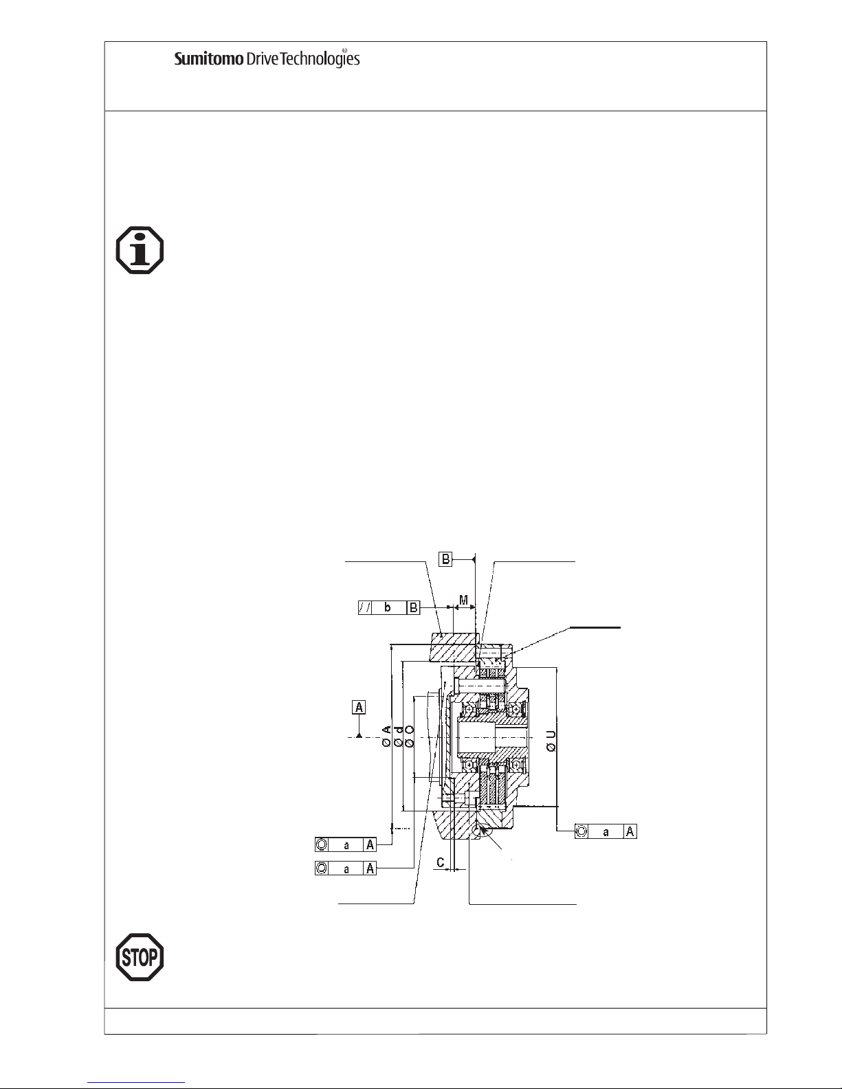
Befestigen Sie den FINE CYCLO FC-AAbtriebswellenflansch an Ihrer Abtriebswelle. Bitte beachten Sie
die geforderten Einbautoleranzen lt. Tab. 1.
Stecken Sie den kompletten Übersetzungsteil auf die Mitnehmerbolzen des Abtriebswellenflansches.
Dabei wird der Abtriebswellenflansch über die Mitnehmerbolzen mit den Mitnehmerrollen des Übersetzungsteils verbunden. Bitte achten Sie darauf, dass keine der Mitnehmerrollen verloren geht. Der
Bolzenring sollte in der vorgesehenen Einbaulage ausgerichtet werden,
bzw.
zentriert sein.
Die FINE CYCLO Getriebe-Einbausätze der Type FC-A werden einbaufertig ausgeliefert.
Jeder Einbausatz wird vor dem Probelauf mit Fett gefüllt und verläßt das Werk mit ausreichender
Fettfüllung und ist somit betriebsbereit und für jede beliebige Einbaulage geeignet.
Die Sicherheitshinweise für den Einbau von Punkt 6 bis 7 sind unbedingt zu beachten.
Nichtbeachtung kann zu Verletzungen, Maschinenschäden sowie Verlust der Gewährleistung führen!
Die FINE CYCLO Getriebe-Einbausätze der Type FC-A werden ohne Lackierung ausgeliefert.
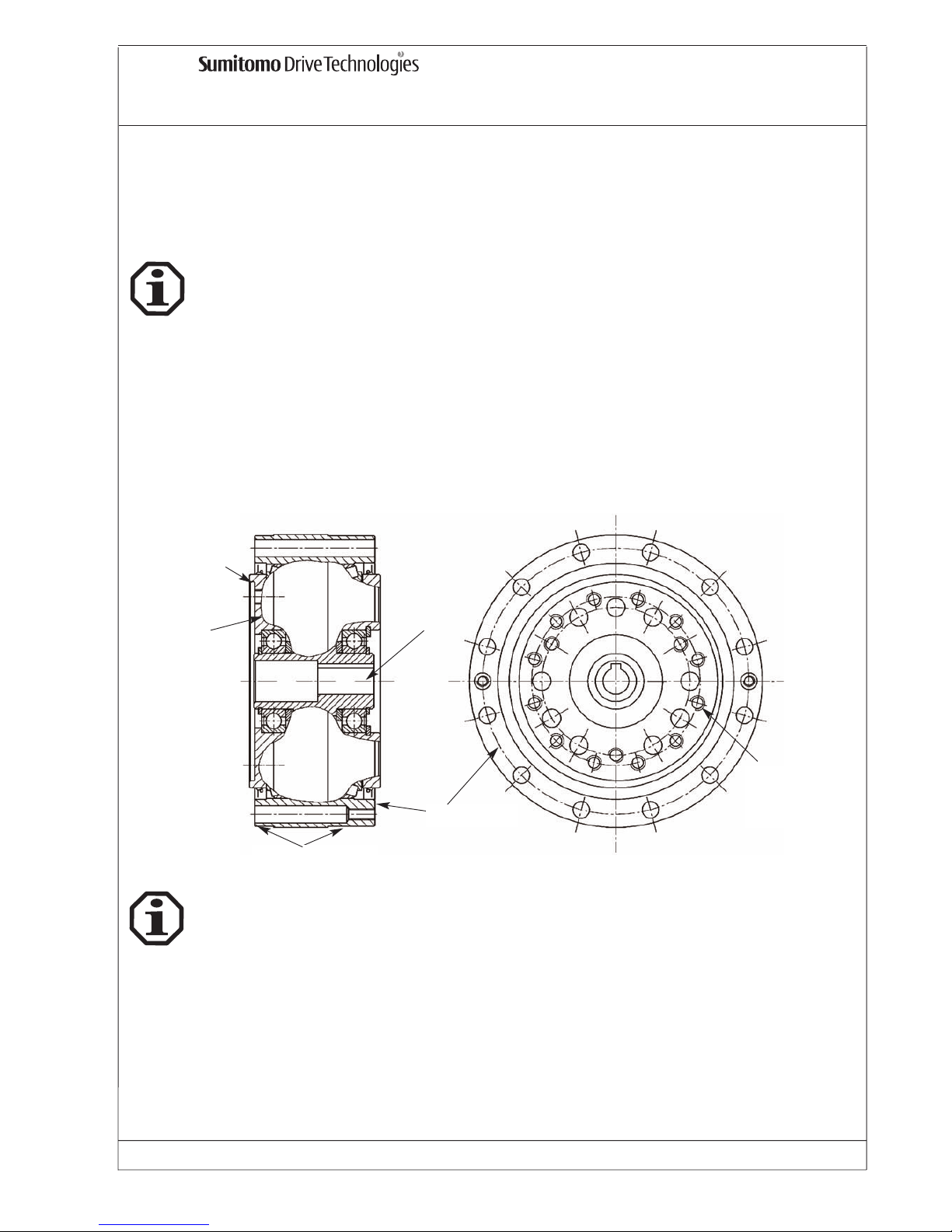
Kundenseitiges
Gehäuse
Bolzenring verschraubt
mit kundenseitigen
Gehäuse
Halterung der Kurvenscheiben
FINE CYCLO Abtriebswellenflansch verschraubt mit kundenseitiger Abtriebswelle
Kundenseitige Abtriebswelle
Abdichtung bei Montage
Zur Sicherung des Abtriebswellenflansches und des Übersetzungsteils sind Zylinderschrauben mit
Innensechskant (Festigkeitsklasse 12.9) DIN EN ISO 4762 zu verwenden. Das Anzugsmoment für diese
Schrauben entnehmen Sie bitte der Tab. 2.
Um z. B. bei starker Vibrationsbeanspruchung ein Lockern der Schrauben zu vermeiden, empfehlen wir
die Verwendung einer flüssigen Schraubensicherung (Loctite Nr. 518 oder 573).
Damit der Haltering für Kurvenscheiben im Gehäuse axial fixiert wird, darf der Innendurchmesser des
Gehäuses “d” aus Tab. 1 die angegebenen Werte nicht überschreiten.
Bei dieser Bearbeitung muss auf absolute Sauberkeit geachtet werden. Besonders der gefettete Übersetzungsteil ist sorgfältig abzudecken.
Für die sichere und einwandfreie Funktion der Einbausätze ist die Einhaltung der vorgegebenen
Anschlußmaße und Toleranzen notwendig.
Ø
Ø
Ø
Page 8

FINE CYCLO Betriebsanleitung
FC_D_01_05 Nr. 991051 Ausgabe: 01/05 Seite 7
In Fällen, in denen mit höheren Grenzdrehmomenten (bitte auch 6.5 beachten) als in T ab. 2 sicher gerechnet
werden muss oder wenn das Schraubenanzugsmoment nicht richtig eingehalten werden kann, wird eine
zusätzliche Verstiftung empfohlen. Bitte Rückfrage bei Sumitomo Drive Technologies. In jedem Fall gelten für die
max. zulässigen Drehmomente der Getriebe die im Katalog genannten Werte. Siehe Tab. 3 und Graphik .
9.2 FC-A Zusätzliche Verstiftung
Schrauben-
anzahl
Größe
DIN 4762
A
nzahl
Zylinderstifte
Zylinderstift-
größe [mm]
Schrauben-
anzahl
Größe
DIN 4762
A
nzahl
Zylinderstifte
Zylinderstift-
größe [mm]
15G 10 M5 2 6 6 M5 2 6
25G 10 M6 2 8 6 M6 2 8
35G 10 M8 2 10 6 M8 2 10
45G 10 M10 2 12 10 M8 2 10
65G 10 M12 2 16 10 M10 2 14
75G 9 M12 3 16 9 M10 3 16
Abtriebswellenflansch Bolzenring
FC-A
Tab. 3: Verstiften
Schrauben-
anzahl
Größe
DIN 4762
Anzugsmoment
pro Schraube* [Nm]
Schrauben-
anzahl
Größe
DIN 4762
A
nzugsmoment
pro Schraube*
[Nm]
15G 12 M5 9.2 8 M5 9.2 470
25G 12 M6 16 8 M6 16 830
35G 12 M8 39 8 M8 39 1900
45G 12 M10 77 12 M8 39 3550
65G 12 M12 135 12 M10 77 7000
75G 12 M12 135 12 M10 77 8000
zulässiges
übertragbares
Drehmoment durch
Schrauben [Nm] T2t
* bei Schraubenqualität 12.9 - Alle Schrauben sind zu verwende
n
Abtriebsseitige Flanschschrauben Bolzenring-Schrauben
FC-A
Tab. 2: Befestigung
Die Tiefe der Zentrierung der Abtriebswelle muss gleich oder größer als das Maß ”C” in Tab. 1 sein. Um
ein Verklemmen des Abtriebswellenflansches zu verhindern, muss das Maß “M” eingehalten werden.
Die empfohlene Genauigkeit Ihres Montageteils (Gehäuse und Abtriebswelle) muss innerhalb der
Koaxialität ”a” und der Parallelität “b” lt. Tab. 1 liegen. Die empfohlenen Durchmesser der Zentriersitze
für Gehäuse, Abtriebswelle und antriebsseitigen Flansch sind “A”, “O” und “U” aus Tab. 1. Der
Außendurchmesser “A” sollte eine feste Verbindung mit Ihrem Gehäuse haben. Da es keine Abdichtung
zwischen Abtriebswellenflansch und Bolzenring gibt, ist vom Kunden eine entsprechend geeignete
Abdichtung an dieser Schnittstelle vorzusehen (flüssiges Dichtungsmaterial z.B. Loctite Nr. 518 oder 573
oder O-Ring am kundenseitigen Gehäuse).
Für die Erhaltung der Funktion, Lebensdauer und Merkmale der Einbausätze ist der Rundlauf der
Wellenenden, die Koaxialität und der Planlauf der Befestigungsflansche nach DIN 42955 N ausreichend. Beim Einsatz in hochpräzisen Applikationen kann die reduzierte Toleranz nach DIN 42955 R
zusätzliche Vorteile bringen.
Das zulässige übertragbare Drehmoment wird auch durch Schrauben begrenzt. Anzahl, Größe und
Anzugsmoment der Schrauben zur Befestigung des abtriebsseitigen Flansches und des Bolzenrings
finden Sie in Tab. 2.
Ø A Ø O Ø U
H7/h7 M7/h7 H7/h7
15 G 90 5 15,5 115 45 85 0.030 0.025/ 87
25 G 115 6 21 145 60 110 0.030 0.035/112
35 G 144 6 24 180 80 135 0.030 0.040/137
45 G 182 8 27 220 100 170 0.030 0.050/172
65 G 226 8 33 270 130 210 0.030 0.065/212
75 G 262 8 38 310 150 235 0.030 0.070/237
Parallelität
b/ bei Ø
Koaxialität
Ø a
FC-A
Zentriersitz Ø [mm]
Ø d
max.
C
min.
M
+
0,3
Tab. 1: Einbautoleranzen
Page 9

FINE CYCLO Betriebsanleitung
FC_D_01_05 Nr. 991051 Ausgabe: 01/05 Seite 8
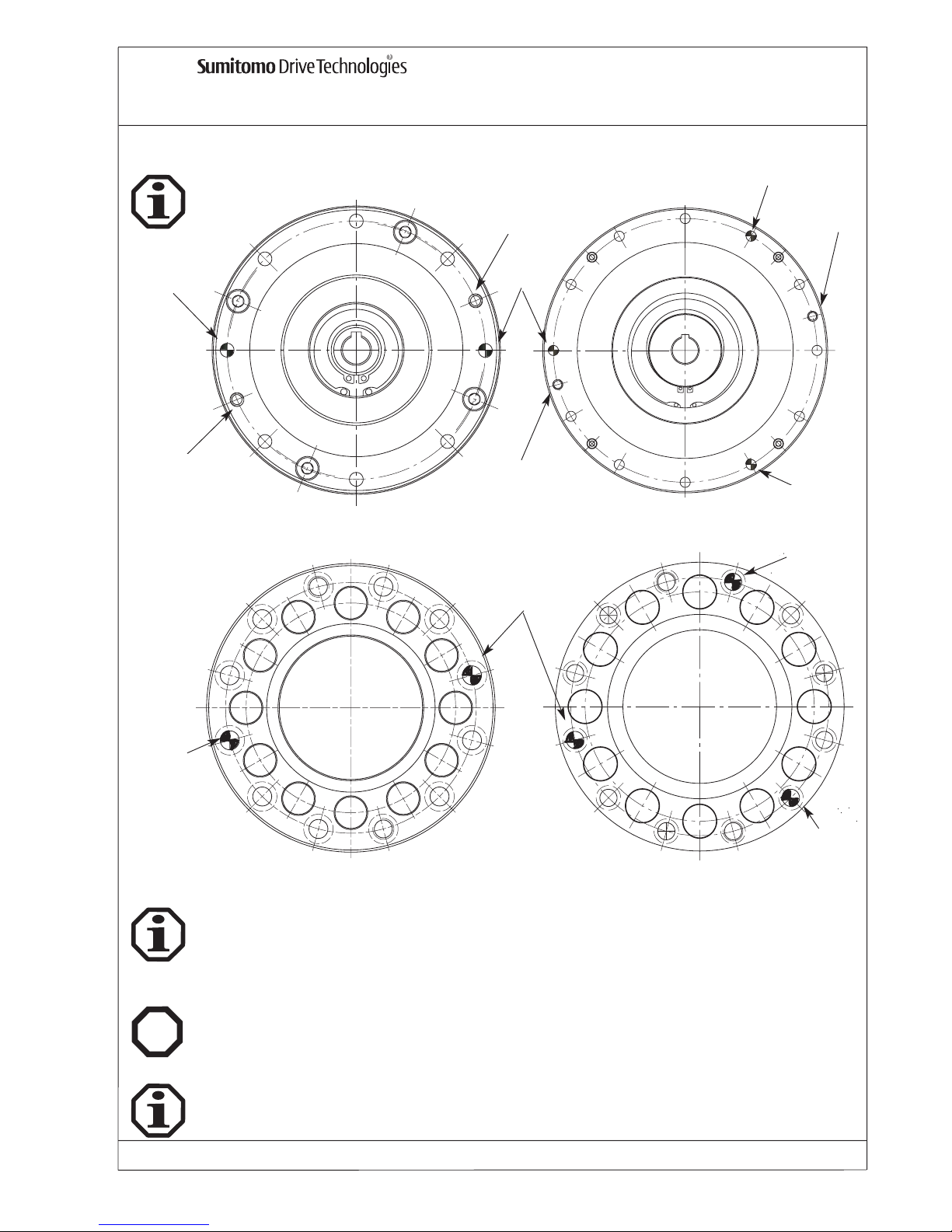
9.3 FC-A Zusätzliche Verstiftung - Graphik
FC-A 15 - 65 FC-A 75
Ex
9.5 FC-A Einsatz im EX-Bereich
Die Getriebe der Baureihe FC-A erfüllen die Anforderungen der Richtlinie 94/9EG, wenn die Einbautoleranzen und Vorschriften zur Befestigung (Tab. 1, Tab. 2 und Tab. 3), sowie die Sicherheitsmaßnahmen
wie unter Punkt 6.6, 6.7 und 7. beschrieben, eingehalten werden.
Die FINE CYCLO Getriebe-Einbausätze FC-A sind lebensdauerfettgeschmiert und für jede Einbaulage
geeignet. .
Durch eine Inspektion und Neufettung im Werk nach 5 Jahren kann die Lebensdauer der Fine Cyclo
Einbausätze verlängert werden.
9.4 FC-A Schmierung und Wartung
Zylinderstift
Zylinderstift
Zylinderstift
Zylinderstift
Gewinde fuer
Demontage
Gewinde fuer
Demontage
Zylinderstift
Zylinderstift
Zylinderstift
Gewinde fuer
Demontage
Zylinderstift
Gewinde fuer
Demontage
FC-A 15-65 FC-A 75
Getriebe
Abtriebswellenflansch
9.6 FC-A Einbauvorschläge
Für Einbauvorschläge siehe Katalog Präzisionsgetriebe 991008.
Page 10

FC_D_01_05 Nr. 991051 Ausgabe: 01/05
Seite 9
10. F1C-A Standard Einbausatz mit abtriebsseitiger Kreuzrollenlagerung
Das zulässige übertragbare Drehmoment (siehe Tab. 1) wird auch durch Schrauben begrenzt. Anzahl,
Größe und Anzugsmoment der Schrauben zur Befestigung des abtriebsseitigen Flansches und des
Bolzenrings finden Sie in Tab. 1. Hierzu Hinweis unter 6.5 beachten.
Der abtriebsseitige Flansch ist an der anzutreibenden Welle der Maschine zu befestigen. Die
Befestigungsschrauben sind entsprechend den Angaben auf Tab. 1 anzuziehen. Für den Anbau des
Motors an den antriebsseitigen Flansch ist ein Adapter erforderlich (siehe Einbauvorschläge im Katalog).
Bei Standardeinbauten mit Hohlwelle und Paßfedernut ist auf die Motorwelle MoS
2
-Paste oder Spray
(z. B. Molykote) aufzutragen. Bei Ausführungen mit antriebsseitigem Klemmring müssen die
Verbindungsstellen öl- und fettfrei sein.
10.1 F1C-A Montageanleitung
10.2 F1C-A Schraubenanzugsmoment und zulässiges Drehmoment
T ab. 1
FINE CYCLO Betriebsanleitung
Die FINE CYCLO Getriebe-Einbausätze der Type FC1-A werden einbaufertig ausgeliefert.
Jeder Einbausatz wird vor dem Probelauf mit Fett gefüllt und verläßt das Werk mit ausreichender
Fettfüllung und ist somit betriebsbereit und für jede beliebige Einbaulage geeignet.
Die Sicherheitshinweise für den Einbau von Punkt 6 bis 7 sind unbedingt zu beachten.
Nichtbeachtung kann zu Verletzungen, Maschinenschäden sowie Verlust der Gewährleistung führen!
10.3 F1C-A Schmierung und Wartung
Die Fine Cyclo Getriebe-Einbausätze F1C-A der Größen 15 bis 35 sind lebensdauerfettgeschmiert
(ESSO UNIREX N2) und für jede Einbaulage geeignet.
Die Kreuzrollenlager der Einbausätze F1C-A Größen 45G, 65G und 75G erfordern nach jeweils 4.000
Betriebsstunden eine Nachschmierung. Nachschmiermengen der Kreuzrollenlager für F1C-A Serie und
Fettsorte siehe Tab. 2, als Anhaltspunkt für trockene, saubere Räume.
Die Nachschmiermengen müssen je nach den vorherrschenden Umgebungsbedingungen korrigiert werden.
Beim Nachschmieren sollten die Lager gedreht werden, damit das frische Fett gleichmäßig verteilt wird.
Durch eine Inspektion und Neufettung im Werk nach 5 Jahren kann die Lebensdauer der Fine Cyclo
Einbausätze verlängert werden.
Die FINE CYCLO Getriebe-Einbausätze der Type FC1-A werden ohne Lackierung ausgeliefert.
Tab. 2 Fettmengen/-sorte Nachschmierung Kreuzrollenlager
45 G SHELL ALVANIA EPLF2 ~ 23 g ~ 10 - 15 g 4.000 h
65 G SHELL ALVANIA EPLF2 ~ 62 g ~25 - 30 g 4.000 h
75 G ESSO BEACON EP2 ~ 108 g ~45 - 50 g 4.000 h
* jedoch mindestens alle 6 Monate
Frist
F1C-A
Fettsorte Menge Erstbefettung Nachschmiermenge
Beim Umgang mit Schmierstoffen und Korrosionsschutzmitteln sind die Schutzvorschriften für Mensch
und Umwelt gemäß den entsprechenden Sicherheitsdatenblättern nach DIN 52 900 zu beachten.
Schrauben-
anzahl
Größe
DIN 4762
A
nzugsmoment
pro Schraube*
[Nm]
Schrauben-
anzahl
Größe
DIN 4762
Anzugsmoment
pro Schraube* [Nm]
15 12 M6 16 12 M6 16 750
25 12 M8 39 12 M8 39 1700
35 12 M10 77 12 M10 77 3150
45 G 12 M14 210 16 M10 77 3550
65 G 16 M16 330 20 M12 135 7000
75 G 16 M16 330 20 M12 135 8000
Bolzenring-Schrauben
Zulässiges übertragbares
Drehmoment
durch Schrauben [Nm] T2t
* bei Schraubenfesstigkeitsklasse 12.9 - alle Schrauben sind zu verwenden!
F1C-A
Abtriebsseitige Flanschschrauben
Page 11

FINE CYCLO Betriebsanleitung
FC_D_01_05 Nr. 991051 Ausgabe: 01/05 Seite 10
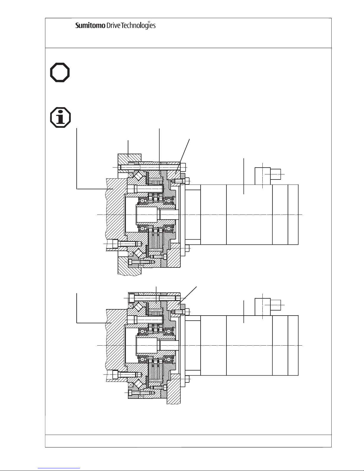
10.5 F1C-A Einbauvorschläge
Siehe auch Katalog Präzisionsgetriebe 991008.
Die Getriebe der Baureihe F1C-A erfüllen die Anforderungen der Richtlinie 94/9EG, wenn die Einbautoleranzen und Vorschriften zur Befestigung (Tab. 1), sowie die Sicherheitsmaßnahmen wie unter Punkt
6.6, 6.7 und 7. beschrieben, eingehalten werden.
10.4 F1C-A Einsatz im EX-Bereich
Ex
Kundenseitige Abtriebswelle
Fine Cyclo
Kundenseitiges Gehäuse
Zwischenflansch für Motor
Motor
Kundenseitige
Abtriebswelle
Fine Cyclo
Zwischenflansch für Motor/Kundenseitiges Gehäuse
Motor
Page 12
FINE CYCLO Betriebsanleitung
FC_D_01_05 Nr. 991051 Ausgabe: 01/05 Seite 11
11.1 F2C-A Montageanleitung
11. F2C-A Einbausatz mit integrierter Kegelrollenlagerung
Der abtriebsseitige Flansch ist an der anzutreibenden Welle der Maschine zu befestigen. Die
Befestigungsschrauben sind entsprechend den Angaben auf Tab. 1 anzuziehen. Für den Anbau des
Motors an den Bolzenring ist ein Adaptor erforderlich (der antriebsseitige Flansch dreht mit
Abtriebsdrehzahl mit) - siehe hierzu Zeichnung unten:
Die FINE CYCLO Getriebe-Einbausätze der Type F2C-A werden einbaufertig ausgeliefert.
Jeder Einbausatz wird vor dem Probelauf mit Fett gefüllt und verläßt das Werk mit ausreichender
Fettfüllung und ist somit betriebsbereit und für jede beliebige Einbaulage geeignet.
Die Einbausätze werden ohne Lackierung ausgeliefert.
Bei Standardeinbauten mit Hohlwelle und Paßfedernut ist auf die Motorwelle MoS2-Paste oder Spray
(z. B. Molykote) aufzutragen. Bei Ausführungen mit antriebsseitigem Klemmring müssen die
Verbindungsstellen öl- und fettfrei sein.
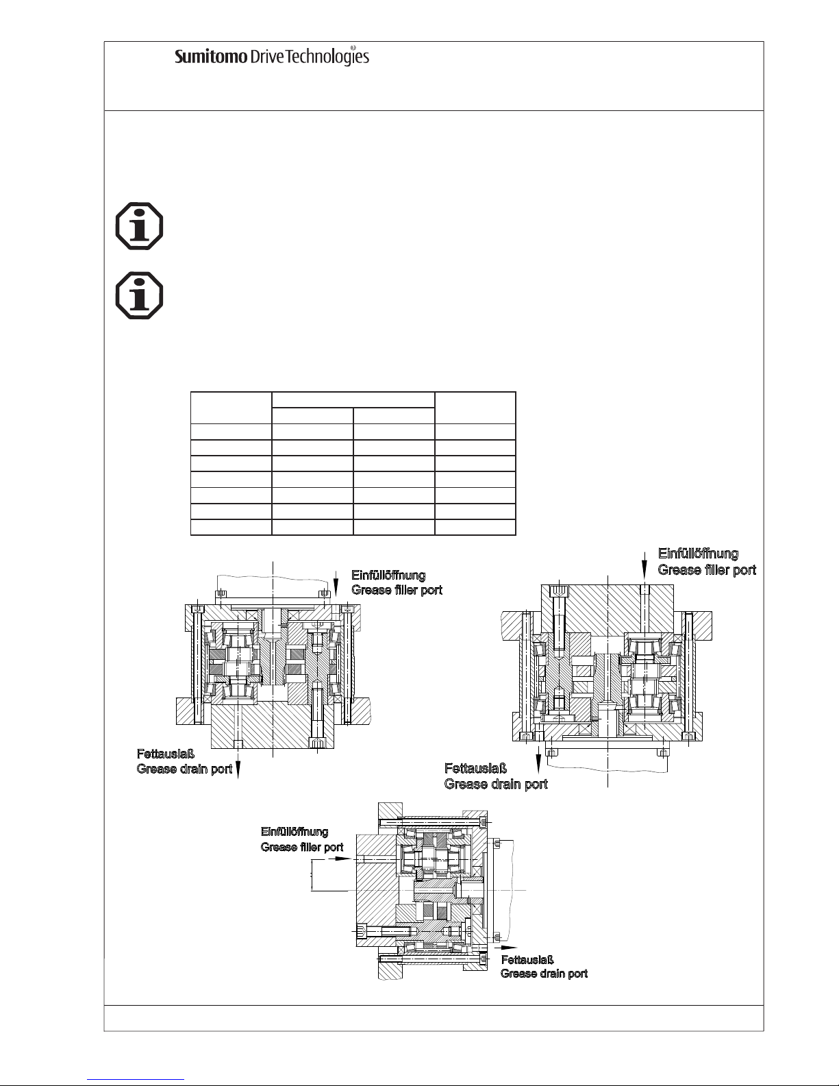
Einbauzentrierung
Abtriebsflansch
Zentrierung
Abtriebsflansch
Bolzenring
Befestigungsgewinde
Abtriebsflansch
antriebsseitige
Hohlwelle
Die Sicherheitshinweise für den Einbau von Punkt 6 bis 7 sind unbedingt zu beachten.
Nichtbeachtung kann zu Verletzungen, Maschinenschäden sowie Verlust der Gewährleistung führen!
Die FINE CYCLO Getriebe-Einbausätze der Type F2C-A werden ohne Lackierung ausgeliefert.
Page 13

FINE CYCLO Betriebsanleitung
FC_D_01_05 Nr. 991051 Ausgabe: 01/05 Seite 12
11.2 F2C-A Schraubenanzugsmoment und zulässige Drehmomente
Die FINE CYCLO Getriebe-Einbausätze F2C-A sind lebensdauerfettgeschmiert und für jede Einbaulage
geeignet.
Durch eine Inspektion und Neufettung im Werk nach 5 Jahren kann die Lebensdauer der Fine Cyclo
Einbausätze verlängert werden.
Das zulässige übertragbare Drehmoment (siehe Tab. 1) wird durch die Verschraubung begrenzt. Anzahl,
Größe und Anzugsmoment der Schrauben zur Befestigung des abtriebsseitigen Flansches und des
Bolzenrings finden Sie in Tab. 1.
11.3 F2C-A Schmierung und Wartung
Tab. 1
11.4 F2C-A Einsatz im EX-Bereich
Die Getriebe der Baureihe F2C-A erfüllen die Anforderungen der Richtlinie 94/9EG, wenn die Einbautoleranzen und Vorschriften zur Befestigung (Tab. 1), sowie die Sicherheitsmaßnahmen wie unter Punkt
6.6, 6.7 und 7. beschrieben, eingehalten werden.
Ex
Schrauben-
anzahl
Größe
DIN 4762
Anzugsmoment
pro Schraube * [Nm] T2t
Schrauben-
anzahl
Größe
DIN 4762
Anzugsmoment pro
Schraube * [Nm] T2t
15 12 M6 16 16 M6 16 700
25 12 M8 39 12 M8 39 1500
35 12 M10 77 16 M8 39 3200
45 12 M14 210 12 M12 135 8200
* bei Schraubenfestigkeitsklasse 12.9 - alle Schrauben sind zu verwenden!
Zulässiges übertragbares
Drehmoment
durch Schrauben [Nm] T2t
Bolzenring-Schrauben
F2C-A
Abtriebsseitige Schrauben
Page 14

FINE CYCLO Betriebsanleitung
FC_D_01_05 Nr. 991051 Ausgabe: 01/05 Seite 13
12. F3C-A Einbausatz mit Gehäuse und Abtriebswelle
12.1 F3C-A Montageanleitung
Die Abtriebswelle ist an der anzutreibenden Welle der Maschine zu befestigen. Die
Befestigungsschrauben sind entsprechend den Angaben auf Tabelle 1 anzuziehen. Für den Anbau des
Motors an den antriebsseitigen Flansch ist ein Adapter erforderlich.
Bei Standardeinbauten mit Hohlwelle und Paßfedernut ist auf die Motorwelle MoS
2
-Paste oder Spray
(z. B. Molykote) aufzutragen. Bei Ausführungen mit antriebsseitigem Klemmring müssen die
Verbindungsstellen öl- und fettfrei sein. Siehe auch 6.5.
Tab. 1
12.3 F3C-A Schraubenanzugsmoment und zulässige Drehmomente
Das zulässige übertragbare Drehmoment (siehe Tab.1) wird auch durch Schrauben begrenzt. Anzahl,
Größe und Anzugsmoment der Schrauben zur Befestigung des abtriebsseitigen Flansches und des
Gehäuses finden Sie in Tab. 1.
Schraubenanzahl
Größe
DIN 4762
Anzugsmoment
pro Schraube * [Nm]
15 G 8 M6 16 550
25 G 8 M6 16 1000
35 G 8 M8 39 2100
45 G 12 M8 39 4000
65 G 12 M10 77 7700
75 G 12 M10 77 9000
* bei Schraubenfestigkeitsklasse 12.9 - alle Schrauben sind zu verwenden!
Abtriebsseitige Flanschschrauben
F3C-A
Zulässiges
übertragbares
Drehmoment durch
Schrauben [Nm] T2t
12.2 F3C-A Lackierung
Die Einbausätze F3C-A werden mit einer Zweikomponentenlackierung auf Polyurethanbasis nach RAL
9005 (tief-schwarz) ausgeliefert.
Die FINE CYCLO Getriebe-Einbausätze der Type FC3-A werden einbaufertig ausgeliefert.
Jeder Einbausatz wird vor dem Probelauf mit Fett gefüllt und verläßt das Werk mit ausreichender
Fettfüllung und ist somit betriebsbereit und für jede beliebige Einbaulage geeignet.
Die Sicherheitshinweise für den Einbau von Punkt 6 bis 7 sind unbedingt zu beachten.
Nichtbeachtung kann zu Verletzungen, Maschinenschäden sowie Verlust der Gewährleistung führen!
Die FINE CYCLO Getriebe-Einbausätze F3C-A sind lebensdauerfettgeschmiert und für jede Einbaulage
geeignet. Als Standardfett wird ESSO UNIREX N2 verwendet.
Durch eine Inspektion und Neufettung im Werk nach 5 Jahren kann die Lebensdauer der Fine Cyclo
Getriebe-Einbausätze verlängert werden.
12.4 F3C-A Schmierung und Wartung
12.5 F3C-A Einsatz im EX-Bereich
Die Getriebe der Baureihe F3C-A erfüllen die Anforderungen der Richtlinie 94/9EG, wenn die Einbautoleranzen und Vorschriften zur Befestigung (Tab. 1), sowie die Sicherheitsmaßnahmen wie unter Punkt
6.6, 6.7 und 7. beschrieben, eingehalten werden.
Ex
Page 15
FINE CYCLO Betriebsanleitung
FC_D_01_05 Nr. 991051 Ausgabe: 01/05 Seite 14
13. F2C-T Einbausatz mit integrierter Kegelrollenlagerung
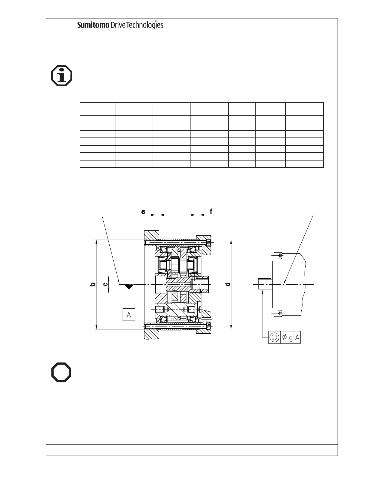
Die FINE CYCLO Getriebe-Einbausätze der Type F2C-T werden ohne Fett ausgeliefert und
müssen vor Inbetriebnahme erst gemäß Tab. 1 mit Fett Multemp FZ No.00, alternativ mit Shell Alvania
EP Fett R0, gefüllt und abgedichtet werden. (Fetteinfüllöffnung siehe Abbildung unten). Diese Fette sind
für Umgebungstemperatur von - 10°C bis + 40°C geeignet.
Nach der Fettbefüllung wie beschrieben sind die Einbausätze lebensdauerfettgeschmiert.
Durch eine Inspektion und Neufettung im Werk nach 5 Jahren kann die Lebensdauer der Fine Cyclo
Einbausätze verlängert werden.
13.1 F2C-T Montageanleitung
vertikal horizontal
155 80 60 25
255 120 100 31
355 230 180 39
455 300 240 47
555 400 320 55
655 700 560 63
755 800 640 73
Fettmenge [g] *
A[mm]F2C-T
Tab. 1
*: Die Fettmenge bezieht sich auf das
Getriebe.
Der Hohlraum zwischen Getriebe und
Motor (Zwischenflansch) ist zusätzlich
zu berücksichtigen:
Horizontal: 50%
Vertikal 1: 100%
Vertikal 2: 100%
13.2 F2C-T Schmierung / Fettbefüllung vor Montage
Die Einbausätze werden ohne Lackierung ausgeliefert.
Die Sicherheitshinweise für den Einbau von Punkt 6 bis 7 sind unbedingt zu beachten.
Nichtbeachtung kann zu Verletzungen, Maschinenschäden sowie Verlust der Gewährleistung führen!
Vertikal 1
Vertikal 2
Horizontal
A
Page 16

FINE CYCLO Betriebsanleitung
FC_D_01_05 Nr. 991051 Ausgabe: 01/05 Seite 15
Für die Montage müssen alle kundenseitigen Schrauben mit dem richtigen Anzugsmoment nach Tab. 2
festgeschraubt werden. Die Schraubenfestigkeit muss mindestens Qualität 10.9 sein.
Der abtriebsseitige Flansch ist an der anzutreibenden Welle der Maschine zu befestigen.
Die Befestigungsschrauben sind entsprechend den Angaben auf Tab. 2 anzuziehen. Für den Anbau des
Motors an den antriebsseitigen Flansch ist ein Adapter erforderlich, der mitgeliefert werden kann. In
diesem Adapter ist ein W ellendichtring vorzusehen. Die Antriebswelle des Getriebes ist nicht im Getriebe
gelagert.
13.3 F2C-T Anzugsmomente
Schrauben-
anzahl **
Größe
DIN 4762
Teilkreis
Durchm.
[mm]
Anzugsmoment
pro
Schraube*
[Nm]
Zul. übertrag-
bares
Drehmoment
[Nm] T2t
Schrauben-
anzahl **
Größe
DIN 4762
Teilkreis
Durchm.
[Nm]
Anzugs-
moment
pro
Schraube*
[Nm]
Zul. Übertrag-
bares
Drehmoment
[Nm] T2t
6 M 6 45 14
3 M 8 66 33 970 16 M 6 114 14 1250
6 M 8 72 33
6 M 12 84 115
3 M 8 82 33 2160 12 M 8 142 33 2120
6 M 8 50 33
6 M 14 104 180
3 M 12 102 115 4500 16 M 8 171 33 3400
6 M 12 63 115
6 M 16 135 280
3 M 12 129 115 7250 12 M 12 210 115 7400
6 M 12 93 115
6 M 18 165 390
3 M 14 150 180 11200 16 M 12 240 115 11300
6 M 14 115 180
6 M 22 180 750
3 M 16 170 280 18200 16 M 14 272 180 17300
6 M 16 115 280
6 M 24 200 950
3 M 18 190 390 24000 16 M 16 305 280 27000
6 M 18 130 390
* bei Schaubenfesigkeitsklasse mind. 10.9
** alle Schrauben müssen verwendet werden
F2C-T
A
btriebswelle Bolzenrin
g
155
255
355
455
555
655
755
13.4 F2C-T Schraubenanzugsmomente - Tab. 2
Bei Standardeinbauten mit Hohlwelle und Paßfedernut ist die Antriebswelle des Getriebes mit der stirnseitigen Gewindebohrung der Motorwelle zu verschrauben. Die Motorwelle muss mit Paßfeder ausgeführt sein.
13.5 F2C-T Einbaubeispiele
Zwischen allen Passungen des Getriebes mit den Kundenanwendungen ist flüssiges Dichtungsmaterial
aufzutragen.
Flüssiges Dichtungsmaterial, Unterlegscheiben für Schrauben sind vom Kunden bereitzustellen und
einzubauen.
13.6 F2C-T Passungen abdichten
Für Einbaubeispiele siehe Katalog Präzisionsgetriebe 991008.
Page 17
FINE CYCLO Betriebsanleitung
FC_D_01_05 Nr. 991051 Ausgabe: 01/05 Seite 16
13.8 F2C-T Einsatz im EX-Bereich
Die Getriebe der Baureihe F2C-T erfüllen die Anforderungen der Richtlinie 94/9EG, wenn die Einbautoleranzen und Vorschriften zur Befestigung (Tab. 2 und Tab. 3), sowie die Sicherheitsmaßnahmen wie
unter Punkt 6.6, 6.7 und 7. beschrieben, eingehalten werden.
Ex
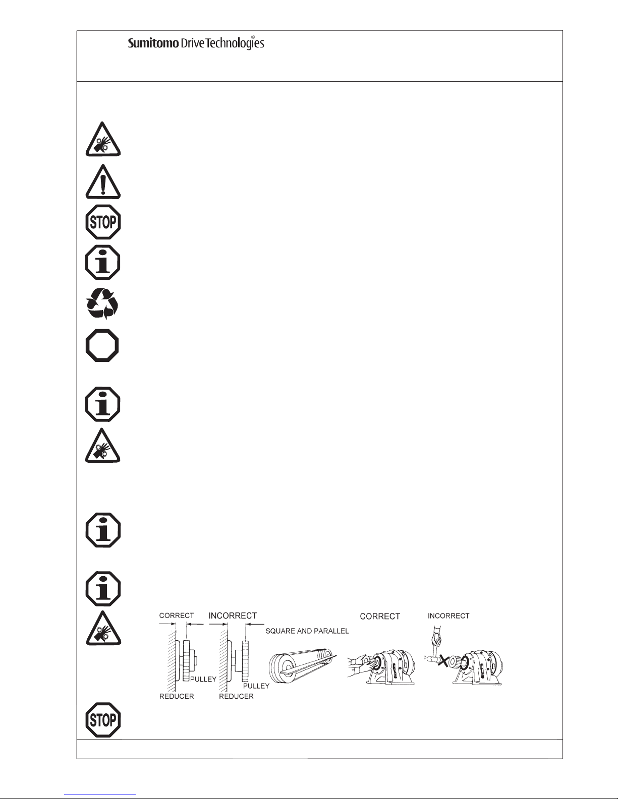
Für die Erhaltung der Funktion, Lebensdauer und Merkmale der Einausätze ist der Rundlauf der
Wellenenden, die Koaxilität und der Planlauf der Befestigunsflansche nach DIN 42955 N ausreichend.
Beim Einsatz in hochpräzisen Applikationen kann die reduzierte Toleranz nach DIN 42955 R zusätzliche
Vorteile bringen. Für Einbautoleranzen siehe Tab. 3.
13.7 F2C-T Einbautoleranzen
F2C-T
Ø b Ø c Ø d e f Ø g
155 125 H7/h7 23,5 H7/h7 125 H7/h7 8 8 0,03
255 155 H7/h7 28 H7/h/ 155 H7/h7 8 8 0,03
355 185 H7/h7 35 H7/h7 185 H7/h7 8 8 0,03
455 230 H7/h7 42 H7/h7 230 H7/h7 10 10 0,03
555 260 H7/h7 47 H7/h7 260 H7/h7 10 10 0,05
655 295 H7/h7 58 H7/h7 295 H7/h7 10 10 0,05
755 330 H7/h7 62 H7/h7 330 H7/h7 15 15 0,05
Tab. 3
Mittelachse der
Drehbewegung
Mittelachse des
Motors
Ø
Ø
Ø
Page 18

FINE CYCLO Operating Manual
FC_GB_01_05 NO.991051 Issue: 01/05 page 1
Copyright 2005 All rights reserved
Reproduction in part or whole is not permitted without
our prior approval.
Whilst every care has been taken in preparation of this
manual, no liability can be accepted for any errors or
omissions.
Subject to technical changes.
Content:
1. General information . . . . . . . . . . . . . . . . . . . . . . . . . . . . . . . . . .2
2. Safety advice . . . . . . . . . . . . . . . . . . . . . . . . . . . . . . . . . . . . . . .2
3. Transportation . . . . . . . . . . . . . . . . . . . . . . . . . . . . . . . . . . . . . .2
4. Connection of other transmission components . . . . . . . . . . . .2
5. Installation procedure . . . . . . . . . . . . . . . . . . . . . . . . . . . . . . . .3
5.1 Necessary tools . . . . . . . . . . . . . . . . . . . . . . . . . . . . . . . . . . . . .3
5.2 Assembly tolerances . . . . . . . . . . . . . . . . . . . . . . . . . . . . . . . . . .3
5.3 To check before installation . . . . . . . . . . . . . . . . . . . . . . . . . . . . .3
5.4 Getting the unit ready for installation . . . . . . . . . . . . . . . . . . . . . . .3
5.5 Installation . . . . . . . . . . . . . . . . . . . . . . . . . . . . . . . . . . . . . . . .3
6. Safety advise for installation of the reduction assembly . . . . .3
6.1 Do not disassemble the reduction parts . . . . . . . . . . . . . . . . . . . . .3
6.2 Protect the reduction assembly . . . . . . . . . . . . . . . . . . . . . . . . . . .3
6.3 Do not exchange components . . . . . . . . . . . . . . . . . . . . . . . . . . .3
6.4 Accuracy of assembly . . . . . . . . . . . . . . . . . . . . . . . . . . . . . . . . . . . .4
6.5 Observation of tigtening torques
. . . . . . . . . . . . . . . . . . . . . . . . . .
4
6.6 Safety advice for explosion protection
. . . . . . . . . . . . . . . . . . . . . .
4
6.7 Safety advice for use with motor/frequency inverter . . . . . . . . . . . . .5
7. Before starting up in hazardeous area . . . . . . . . . . . . . . . . . . .5
8. Disfunctions . . . . . . . . . . . . . . . . . . . . . . . . . . . . . . . . . . . . . . . .5
9. FC-A . . . . . . . . . . . . . . . . . . . . . . . . . . . . . . . . . . . . . . . . . . . .6
10. F1C-A . . . . . . . . . . . . . . . . . . . . . . . . . . . . . . . . . . . . . . . . . . . .9
11. F2C-A . . . . . . . . . . . . . . . . . . . . . . . . . . . . . . . . . . . . . . . . . . .11
12. F3C-A . . . . . . . . . . . . . . . . . . . . . . . . . . . . . . . . . . . . . . . . . . .13
13. F2C-T . . . . . . . . . . . . . . . . . . . . . . . . . . . . . . . . . . . . . . . . . . .14
Page 19
FINE CYCLO Operating Manual
FC_GB_01_05 NO.991051 Issue: 01/05 page 2
Dangerous situation
Risk of physical injury
1. General information
Please observe the following warnings
Helpful information
Disposal
Please observe legal /environmental regulations.
Do not attempt to install or operate the FINE CYCLO reduction assembly until all of these instructions
on assembly, operation, maintenance and inspection and hazards are read and thoroughly understood. Please keep these instructions next to the unit in operation to check at any time when neces-
Transportation, assembly, lubrication, operation, maintenance and inspection should only be done by
qualified personnel, so as to avoid personal injury or damage to property.
Do not touch moving mechanical components and make sure these parts are clear of obstructions.
Failure to follow these instructions may result in personal injury, unit failure or damage to property.
Only operate the unit in the application it was intended. Misapplication may result in physical injury or
damage to machinery.
2. Safety advice
The units must be checked for any transportation damage immediately upon receipt. Any damages
should be reported to the carrier without delay. If there is any evidence of damage which may put at
risk the function of the FINE CYCLO reduction assembly, do not install the unit.
3. Transportation recommendations
In the case of speed reducers with hollow high speed shafts, MoS2paste or spray (e.g. Molykote) is
to be applied to the motor shaft before it is connected.
4. Connection of other transmission components
Imminent danger
Misapplication of the machine may be dangerous and lead to severe injuries
Ex
Important remarks for explosion protection
Clutches, discs, gear wheels, chains, etc. should be mounted on the reducer shafts carefully.
Do not force them onto the shafts as this could damage the gearbox bearings.
Damaging situation
Risk of machine damage.
Page 20

FINE CYCLO Operating Manual
page 3Issue: 01/05FC_GB_01_05 NO.991051
5 . Installation procedure
5.1 Necessary tools
- Screw wrench set
- Torque wrench for fastening screws
- Clamp coupling
- Adjusting elements
- Corrosive protection (e.g. MoS2-Paste)
For assembly tolerances please refer to detailed specifications according to product type.
5.2 Assembly tolerances
- Data on name plate matches with other documents such as drawings, parts list, etc.
- Inspect the reduction assembly for possible damage.
- Provide the recommended lubricants according to the environment of the installation.
5.3 Please check before installation
5.4 Before starting up
The anti-corrosive agent (Valvoline Tectyl 846/K19) used for transportation and storage on the shaftends or hollow shafts, and on the central seats must be removed before start up. This anti-corrosive
agent can be removed using an alkaline detergent; under no circumstances is it to be removed mechanically (abrasive etc.). The alkaline detergent must not come into contact with the seals.
When handling lubricants and anti-corrosive agents please observe the respective safety instructions
for people and environment according to DIN 52 900.
5.5 Installation
The reduction assembly should be installed so that it is easily accessible for any future lubrication or
grease top-up.
Units to be installed outdoors or in very unfavourable ambient conditions, e.g. dirt, dust, spray water or
heat, should be protected by covers. Free air access to the housing surface must not be impaired under
these circumstances.
Grease filler port and grease drain port must also be clear for access.
In case of electrochemical corrosion risk due to contact of different metals such as cast iron and fine
steel, plastic protection of 2 or 3 mm thick should go between gear and machine. Screws should also be
protected by plastic discs. In addition, protect the housing with earthing screws fixed to the motor.
The Fine Cyclo reduction assemblies are suitable for use in ambient temperatures of -10°C to +40°C. In
case of other environments, please consult Sumitomo Drive Technologies:
6. Safety advice for installation of reduction assembly
6.1 Do not disassemble the reduction parts!
The units are built by selective assembly to obtain the best possible performance. Disassembling and
reassembling the units with parts not in their original positions could adversely affect the units performance. The warranty will be void !
6.2 Protect the reduction assembly!
Protect the reduction assembly with extreme care against foreign parts and substances because it is
partially exposed before installation. Therefore, the grease might be contaminated .
6.3 Do not exchange components!
The exchange of components between one unit and another is not permissible, since the units are built
from matched sets of components.
Page 21

FINE CYCLO Operating Manual
FC_GB_01_05 NO.991051 Issue: 01/05 page 4
Accuracy in assembly of the outputshaft and the reducer unit is essential for smooth run of the
unit. Assembly tolerances should be addhered to.
6.4 Accurate assembly
6.5 Ensure that tightening torques are correct
Allowable transmitted torque could be limited by mounting bolts. The recommended bolt grade, quantity, size and tightening torques for the output flange and ring gear housing are shown for each Fine
Cyclo Type at the following chapters.
Care must be taken to ensure the tightening torques are correct. For this purpose we recommend tightening with a torque wrench, with a tightening torque factor of 1,4. The contact surfaces of the housing
and mating component must be clean and dry. When these conditions are achieved the gearbox fasteners will be capable of transmitting the allowable torques as shown for each Fine Cyclo Type in the
following chapters.
“Yield point” controlled tightening according to VDI 2230 increases the allowable transmitted torque by
aprox. 25%.
In the event of a crash situation higher peak torques could occur, which may be transmitted without permanent damage to the gearbox, but in the interests of safety, the fasteners should be checked. In any
case the allowable peak torques for emergency stops are shown in our catalogue 991007.
6.6 Safety advice for explosion protection
Ex
Explosive gas mixtures or dust concentrations may , when combined with hot moving part s on the gears
cause serious or fatal injuries.
Installation, start up, servicing and repairs of both the gear and the electrical device should be done by
qualified personnel and is subject to
- these instructions
- the hazard and information plates on the gear
- all other design documents and circuit diagrams relating to the drive
- the unit-specific regulations and requirements
- standards and regulations in force nationally/regionally (explosion protection, safety, accident
prevention)
Sealing between Fine Cyclo units and
- housing provided by the customer, as well as
- driving motor
must meet the IP 65 class specifications.
A shaft sealing ring should be mounted between the housing and the slow speed shaft for FC-A type.
The shaft sealing rings must be checked for leaks regularly, at least every quarter. If there is any sign
of a leak, the seal must be replaced immediately.
The units must be regularly checked for dust deposits. Any dust deposits thicker than 1 mm must be
removed.
Any add-on parts must not obstruct the discharge of heat through convection and conduction of heat.
Heat radiation from any other equipement is not permissible.
Maximum permissible differential to ambient temperatures is 60 K for all Fine Cyclo reduction assemblies.
Page 22

FINE CYCLO Operating Manual
FC_GB_01_05 NO.991051 Issue: 01/05 Page 5
6.7 Safety advice for use with Motor /Frequency Inverter
Ex
Before starting up a motor connected to the Fine Cyclo units every instructions given before, 5.3 to 6.4,
must be observed.
The use of a frequency invertor conncected to the motor is safe only when all indications given on the
nameplate are kept. The gears are designed for industrial plant and must only be used in accordance
with the information in the technical documentation from Sumitomo Drive Technologies and the data
on the name plate. This corresponds to the current standards and regulations and fulfils the requirements of guideline 94/9EU.
7. Before starting up in hazardous area
Check whether the data on the name plate of the gear unit agrees with the permissible hazardous.
Check for any possible damages on the gear unit due to transport.
When installing the gear, ensure that there is no explosive environment (oils, acids, gases, steam or
rays).
Check that the mounting form agrees with the form given on the gear's name plate.
Please note: a change of mounting form is only permitted after prior consultation with Sumitomo Drive
Technologies, otherwise the ATEX approval lapses.
Ensure that there is enough ventilation to the gear and there is no external heat source (e. g. from cou-
plings).
The temperature of the cooling air must not exceed 40°C.
If possible, the gear should be tested without load. If it runs quietly with no abnormal noise, the gear
can be attached to the machine.
After approx. 3 hours, measure the surface temperature. Check maximum permissible differential to
ambient temperature. In case of higher temperature than maximum indicated for the specific
Fine Cyclo Type, stop the unit immediately and consult Sumitomo Drive Technologies.
8. Disfunctions
In case of any disfunction of the unit please contact Sumitomo Drive Technologies.
Do not disassemble the reduction parts. The units are built by selective assembly to obtain the
best possible performance. Disassembling and reassembling the units with parts not in their original positions could adversely affect the units performance. The warranty will be void (refer to
chapter 6).
Ex
Ex
Page 23
FINE CYCLO Operating Manual
FC_GB_01_05 NO.991051 Issue: 01/05 page 6
9. FC-A reduction assembly - slow speed shaft not supported
The
FINE CYCLO reduction assemblies Type FC-A are shipped pre-finished, ready for use.
Every
FINE CYCLO reduction assemblies FC-A are filled with grease before the test run. They are
lubricated for life and suitable for any mounting position
.
The
FINE CYCLO reduction assemblies Type FC-A are shipped without painting.
These reduction assemblies will be shipped without support bearings for slow speed shaft flange. When
installing into the driven machine, please prepare appropriate bearings which have sufficient stiffness.
Connect the FC-A slow speed shaft flange with the output shaft of your machine. Observe the asssembly tolerances acc. to Tab. 1.
Carefully locate the pins protruding from the output flange into the rollers in the reduction portion, ensuring that none of the rollers are displaced or lost. The ring gear housing can then be located in the recess
provided in your output housing.
To secure the output flanges together and the ring gear housing to the output housing, socket head cap
screws of Grade 12.9 according to DIN EN ISO 4762 should be used. The tightening torques for these
screws are given in Tab. 2.
Applications subject to severe vibrations can result in slackening of the screws. To prevent this, we recommend the use of liquid screwlock (Loctite No. 518 or 573).
To ensure the Cycloid disc retaining ring is trapped by the housing, the inside diameter of the housing
must not exceed “d”, acc. to Tab. 1.
9.1 FC-A installation and assembly procedure
The safety instructions given before, item 6 to 7, are very important, please observe every single item.
Non-observance may cause injuries, machine damage or the warranty may lapse.
customer’s housing
ring gear housing attached
to customers machine
retaining ring
Fine Cyclo slow speed shaft flange attached to
customers machine
customer’s output shaft
sealing during assembly
During the above mentioned work, absolute cleanliness is essential. The exposed areas of the reduction portion must be well protected from any contaminent.
To ensure satisfactory operation of the reduction assembly it is essential to maintain all mounting tolerances recommended.
Ø
Ø
Ø
Page 24

FINE CYCLO Operating Manual
FC_GB_01_05 NO.991051 Issue: 01/05 page 7
In cases where higher torques than those given in Tab. 2 occur (please refer also to 6.5) or if the
tightening torques of the fasteners can not be relied upon, the use of dowel pins is neccesary.
In this case, please contact Sumitomo Drive Technologies.
In any case the allowable peak torques for emergency stops given in our catalogue are valid.In any case
the allowable peak torques for emergency stops given in our catalogue are valid. See tab. 3 & graph.
Number of
bolts
Bolt size
DIN 4762
Number of
dowel pins
Size of
dowel pins
(mm)
Number of
bolts
Bolt size
DIN 4762
Number of
dowel pins
Size of
dowel pins (mm)
15G 10 M5 2 6 6 M5 2 6
25G 10 M6 2 8 6 M6 2 8
35G 10 M8 2 10 6 M8 2 10
45G 10 M10 2 12 10 M8 2 10
65G 10 M12 2 16 10 M10 2 14
75G 9 M12 3 16 9 M10 3 16
FC-A
Slow speed shaft bolts Ring gear pin
Tab. 3
9.2 FC-A additional dowel pins for applications with peak torques higher than those given in Tab. 2
Tab. 2: Fixing
Number of
bolts
Size
DIN 4762
Tightening torque *
[Nm]
Number of
bolts
Size
DIN 4762
Tightening torque
* [Nm]
15G 12 M5 9.2 8 M5 9.2 470
25G 12 M6 16 8 M6 16 830
35G 12 M8 39 8 M8 39 1900
45G 12 M10 77 12 M8 39 3550
65G 12 M12 135 12 M10 77 7000
75G 12 M12 135 12 M10 77 8000
A
llowable
transmitted torque
by bolts [Nm] T2t
* Screw grade 12.9 - All screws to be used!
FC-A
Slow speed shaft bolts Ring gear housing bolts
Ø A Ø O Ø U
H7/h7 M7/h7 H7/h7
15 G 90 5 15,5 115 45 85 0.030 0.025/ 87
25 G 115 6 21 145 60 110 0.030 0.035/112
35 G 144 6 24 180 80 135 0.030 0.040/137
45 G 182 8 27 220 100 170 0.030 0.050/172
65 G 226 8 33 270 130 210 0.030 0.065/212
75 G 262 8 38 310 150 235 0.030 0.070/237
Location diameter Ø [mm]
Parallelism
b/ with Ø
Concentricity
Ø a
FC-A
Ø d
max.
C
min.
M
+
0,3
Tab. 1: Assembly tolerances
The depth of the output shaft flange recess must be equal to or greater than dimension “C”, acc. to
Tab. 1. To ensure the correct clearance the output flange dimension “M” must be maintained.
The recommended concentricity and parallelism accuracy of the mounting components (housing and
output shaft) should be within the figures “a” and “b”, acc. to tab. 1. The recommended location diameters for the housing output flange and motor input adaptor are “A”, “O” and “U”, acc. to Tab. 1
The location diameter “A” should be fixed to the casing. As there is no sealing between output flange
and ring gear housing, the user should provide sealing when assembling (e.g. liquid sealing Loctite
No. 518 or 573) or O-Ring on customer’s housing.
Motors with standard flange concentricity and squareness tolerances according to DIN 42955 are
acceptable for standard applications. For high precision applications we recommend the use of
motors with reduced concentricity and squareness tolerance in accordance with DIN 42955 R.
Allowable transmitted torque could be limited by mounting bolts.The recommended bolt grade, quantity,
size and tightening torques for the output flange and ring gear housing are shown in Tab. 2.
Page 25
Issue: 01/04
Page 8
9.3 FC-A additional dowel pins - graph
FC-A 75
Dowel pin
Dowel pin
Dowel pin
Dowel pin
Thread
Thread
Dowel pin
Dowel pin
Dowel pin
Thread
Dowel
pin
Thread
FC-A 15-65 FC-A 75
Fine Cyclo reduction unit
Slow speed flange
9.4 FC-A l
ubrication and maintenance
The FINE CYCLO reduction assemblies FC-A are grease lubricated for life and suitable for any mounting position.
We recommend the unit is returned to Sumitomo Drive Technologies for inspection and regreasing after
5 years to increase service lifetime.
9.5 FC-A
for use in hazardeous environment
Ex
The
FINE CYCLO reduction assemblies FC-A
fulfil the requirements of guideline 94/9EU, provided
installation is in accordance with the assembly tolerances and assembly methods shown at tab. 1 and
tab. 2, as well as safety instructions shown in chapter 6.6, 6.7 and 7.
FC-A 15-65
9.6 FC-A mounting examples
For mounting examples please refer to Precision Catalogue No. 991007.
FINE CYCLO Operating Manual
FC_GB_01_05 NO.991051
Issue: 01/05
Page 26
FINE CYCLO Operating Manual
FC_GB_01_05 NO.991051 Issue: 01/05 Page 9
10. F1C-A reduction assembly - slow speed shaft with crossroller bearing
Allowable transmitted torque (refer to Tab. 1) could be limited by mounting bolts. The recommended bolt
grade, quantity, size and tightening torques for the output flange and ring gear housing are shown in Tab. 1.
Number of
bolts
Bolt size
DIN 4762
Tightening
torque *[Nm]
Number of
bolts
Bolt size
DIN 4762
Tightening torque
*[Nm]
15 12 M6 16 12 M6 16 750
25 12 M8 39 12 M8 39 1700
35 12 M10 77 12 M10 77 3150
45 G 12 M14 210 16 M10 77 3550
65 G 16 M16 330 20 M12 135 7000
75 G 16 M16 330 20 M12 135 8000
* Screw grade 12.9 - all screws to be used!
Allowable transmitted torque
by bolts [Nm] T2t
Slow speed shaft bolts Ring gear housing bolts
F1C-A
The FINE CYCLO reduction assemblies F1C-A are supplied ready for mounting.
Each reduction assembly is greased before the test run and supplied ready for use and suitable for any
mounting position.
The
FINE CYCLO reduction assemblies Type F1C-A are shipped without painting.
Fit the slow speed flange solidly to the driven shaft of machine. Tighten fixing bolts firmly according to
the instructions on tab. 1.
The motor can be mounted to the input flange by use of a suitable adaptor (see mounting examples
shown at the Precision catalogue No. 991007).
In the case of standard speed reducers with hollow high speed shafts and keyway, MoS2paste or spray
(e.g. Molykote) is to be applied to the motor shaft. When locking ring is used at the input shaft, connections must be free of oil or grease.
10.1 F1C-A installation and assembly procedure
10.2 F1C-A allowable transmitted torque
Tab. 1
The safety instructions given before, item 6 to 7, are very important, please observe every single item.
Non-observance may cause injuries, machine damage or the warranty may lapse.
The FINE CYCLO reduction assemblies F1C-A sizes 15 to 35 are lifetime grease lubricated (ESSO
UNIREX N2) and suitable for any mounting position.
The cross roller bearings of F1C-A sizes 45G, 65G and 75G require regreasing every 4,000 running
hours
. For quantities and type of lubricant for the crossroller bearings see Tab. 2.
Quantities of lubricant should be adjusted according to the ambient conditions. The quantities shown in
tab. 2 should be used as a reference point for clean, dry rooms.
The bearings should be rotated during lubrication to ensure that the lubricant is distributed evenly.
We recommend the unit is returned to Sumitomo Drive Technologies for inspection and regreasing after
5 years to increase service lifetime.
10.4 F1C-A lubrication and maintenance
45 G SHELL ALVANIA EPLF2 ~ 23 g ~ 10 . 15 g 4.000 h *
65 G SHELL ALVANIA EPLF2 ~ 62 g ~25 - 30 g 4.000 h *
75 G ESSO BEACON EP2 ~ 108 g ~45 - 50 g 4.000 h *
* no longer than 6 months
time period
F1C-A
Lubricant Initital lubrication Subsequent lubrication
Tab. 2 Lubricant, grease quantity for relubrication of cross roller bearings
Please observe legal /environmental regulations when handling grease or other chemicals.
Page 27
FC_GB_01_05 NO.991051 Issue: 01/05
Page 10
10.3 F1C-A mounting examples
Pplease refer also to Precision Catalogue No. 991007.
10.5 F1C-A
for use in hazardeous environment
Ex
The
FINE CYCLO reduction assemblies F1C-A
fulfil the requirements of guideline 94/9EU, provided
installation is in accordance with the assembly tolerances and assembly methods shown at Tab. 1 and
Tab. 2, as well as safety instructions shown in chapter 6.6, 6.7 and 7.
FINE CYCLO Operating Manual
Customer’s Output Shaft
Fine Cyclo
Customer’s Casing
Motor Adaptor
Motor
Customer’s
Output Shaft
Fine Cyclo
Motor Adaptor/Customer’s Casing
Motor
Page 28
FINE CYCLO Operating Manual
FC_GB_01_05 NO.991051 Issue: 01/05 Page 11
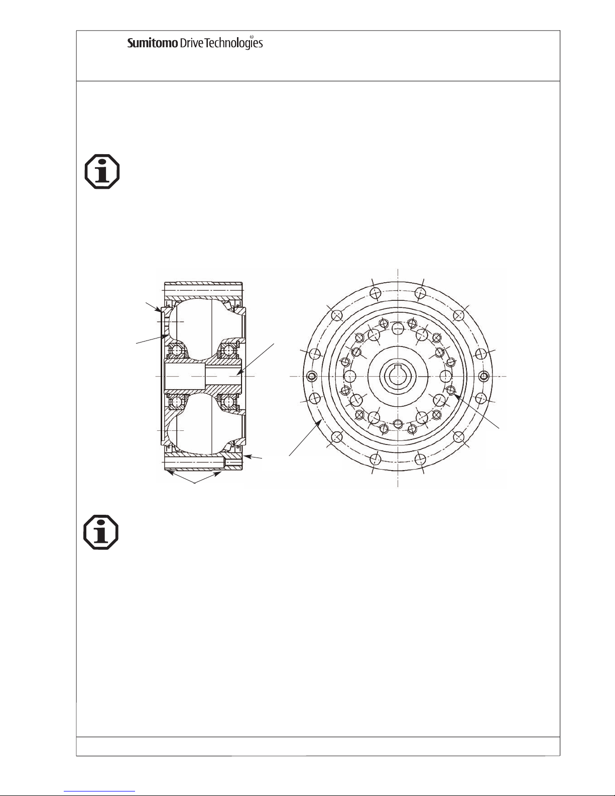
11.1 F2C-A installation and assembly procedure
11. F2C-A reduction assembly
In the case of standard speed reducers with hollow high speed shafts and keyway, MoS2paste or spray
(e.g. Molykote) is to be applied to the motor shaft. When locking ring is used at the input shaft, connections must be free of oil or grease.
The
FINE CYCLO reduction assemblies Type F2C-A are shipped without painting.
The FINE CYCLO reduction assemblies F2C-A are supplied ready for mounting.
Each reduction assembly is greased before the test run and supplied ready for use and suitable for any
mounting position.
Fit the slow speed flange solidly to the driven shaft of machine. Tighten fixing bolts firmly according to
the instructions on Tab. 1. The motor can be mounted to the input flange (turns with output speed) by
use of a suitable adaptor - refer to drawing below:
The safety instructions given before, item 6 to 7, are very important, please observe every single item.
Non-observance may cause injuries, machine damage or the warranty may lapse.
Installation centering
Slow speed
shaft
Centering
Ring gear housing
Fixing thread
slow speed
shaft
Input hollow
shaft
Page 29

FINE CYCLO Operating Manual
FC_GB_01_05 NO.991051 Issue: 01/05 Page 12
Allowable transmitted torque (Tab. 1) could be limited by mounting bolts. The recommended bolt grade, quantity, size
and tightening torques for the output flange and ring gear housing are shown in Tab. 1.
11.3 F2C-A lubrication and maintenance
The FINE CYCL reduction assemblies F2C-A are lifetime greased and suitable for any mounting position.
We recommend the unit is returned to Sumitomo Drive Technologies for inspection and regreasing after
5 years to increase service lifetime.
Tab. 1
11.2 F2C-A allowable transmitted torque
Number of
bolts
Bolt size
DIN 4762
Tightening
torque *[Nm]
Number of
bolts
Bolt size
DIN 4762
Tightening
torque * [Nm] T2t
15 12 M6 16 16 M6 16 700
25 12 M8 39 12 M8 39 1500
35 12 M10 77 16 M8 39 3200
45 12 M14 210 12 M12 135 8200
* Screw grade 12.9 - all screws to be used!
Allowable transmitted torque
by bolts [Nm] T2t
Slow speed shaft bolts Ring gear housing bolts
F2C-A
11.4 F2C-A
for use in hazardeous environment
Ex
The
FINE CYCLO reduction assemblies F2C-A
fulfil the requirements of guideline 94/9EU, provided
installation is in accordance with the assembly tolerances and assembly methods shown at tab. 1, as
well as safety instructions shown in chapter 6.6, 6.7 and 7.
Page 30

FINE CYCLO Operating Manual
FC_GB_01_05 NO.991051 Issue: 01/05 Page 13
12. F3C-A reduction assembly
12.1 F3C-A installation and assembly procedure
Tab. 1
12.3 F3C-A allowable transmitted torque
12.2 F3C-A painting
The exterior finish of F3C-A reduction assembly is a two paint on a polyurethan basis correspondend to RAL 9005 (jet black).
The safety instructions given before, item 6 to 7, are very important, please observe every single item.
Non-observance may cause injuries, machine damage or the warranty may lapse.
The FINE CYCLO reduction assemblies F3C-A are supplied ready for mounting.
Each reduction assembly is greased before the test run and supplied ready for use and suitable
for any mounting position.
Fit the slow speed flange solidly to the driven shaft of machine. Tighten fixing bolts firmly according to
the instructions on tab. 1. The motor can be mounted to the input flange by use of a suitable adaptor
In the case of standard speed reducers with hollow high speed shafts and keyway, MoS
2
paste or spray
(e.g. Molykote) is to be applied to the motor shaft.
When locking ring is used at the input shaft, connections must be free of oil or grease. Please refer
to 6.5.
Allowable transmitted torque could be limited by mounting bolts. The recommended bolt grade, quantity, size and tightening torques for the output flange and ring gear housing are shown in Tab. 1.
Number of bolts
Size
DIN 4762
Tightening torque *
[Nm]
15 G 8 M6 16 550
25 G 8 M6 16 1000
35 G 8 M8 39 2100
45 G 12 M8 39 4000
65 G 12 M10 77 7700
75 G 12 M10 77 9000
* Screw grade 12.9 - all screws to be used!
F3C-A
Slow speed shaft bolts Allowable transmitted
torque by bolts* [Nm]
T2t
12.4 F3C-A - lubrication and maintenance
The FINE CYCLO reduction assemblies F3C-A are grease lubricated for life and suitable for any mounting position. The lubricant used is ESSO UNIREX N2 grease.
We recommend the unit is returned to Sumitomo Drive Technologies for inspection and regreasing after
5 years to increase service lifetime.
12.5 FC3-A
for use in hazardeous environment
Ex
The
FINE CYCLO reduction assemblies F3C-A
fulfil the requirements of guideline 94/9EU, provided
installation is in accordance with the assembly tolerances and assembly methods shown at tab. 1 and
tab. 2, as well as safety instructions shown in chapter 6.6, 6.7 and 7.
Page 31
FINE CYCLO Operating Manual
FC_GB_01_05 NO.991051 Issue: 01/05 Page 14
13. F2C-T reduction assembly with integrated roller bearings
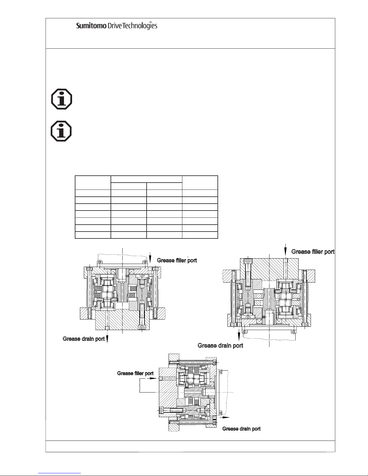
The reduction assembly series FINE CYCLO Type F2C-T are drained of grease at the time of shipment,
please be sure to fill the unit with grease Multemp FZ No.00 or Shell Alvania EP GreaseR0, quantities according to tab. 1 (grease filler port position see picture below). These greases are suitable for
operating temperatures of -10°C to +40°C.
After the units have been properly filled with grease, the are lifetime lubricated.
We recommend the unit is returned to Sumitomo Drive Technologies for inspection and regreasing after
5 years to increase service lifetime.
13.1 F2C-T installation and assembly procedure
Tab. 1
*:Note:
Grease quantity is valid for the gearbox
itself only.
For the space between gearbox and intermediate flange additional quantities have
to be considered accordingly:
Horizontal: 50%
Vertical 1: 100%
vertical 2: 100%
The safety instructions given before, item 6 to 7, are very important, please observe every single item.
Non-observance may cause injuries, machine damage or the warranty may lapse.
The
FINE CYCLO reduction assemblies Type F2C-T are shipped without painting.
Vertical 1
Vertical 2
Horizontal
13.2 F2C-T lubrication prior assembly
A
vertical horizontal
155 80 60 25
255 120 100 31
355 230 180 39
455 300 240 47
555 400 320 55
655 700 560 63
755 800 640 73
Grease quantity [g] *
A[mm]F2C-T
Page 32

FINE CYCLO Operating Manual
FC_GB_01_05 NO.991051 Issue: 01/05 Page 15
For installation, all bolts connecting the reduction units to the machine must be tightened to the correct
torque according to Tab. 2. Bolts must be grade 10.9. or higher.
Fit the slow speed flange solidly to the driven shaft of the machine. Tighten fixing bolts firmly according
to the instructions on Tab. 2.
To mount the motor to the input flange an adaptor is required. This adaptor is available on request.
The adaptor requires an oil seal.
The input shaft has no bearings in the reduction assembly.
13.3 F2C-T tightening torques
Number of
bolts**
Size
DIN 4762
P.C.D.
[mm]
Tightening
torque *
[Nm]
Allowable
transmitted
torque by
bolts
[Nm]
T2
t
Number of
bolts**
Size
DIN 4762
P.C.D.
[mm]
Tightening
torque *
[Nm]
Allowable
transmitted
torque by bolts
[Nm] T2t
6 M 6 45 14
3 M 8 66 33 970 16 M 6 114 14 1250
6 M 8 72 33
6 M 12 84 115
3 M 8 82 33 2160 12 M 8 142 33 2120
6 M 8 50 33
6 M 14 104 180
3 M 12 102 115 4500 16 M 8 171 33 3400
6 M 12 63 115
6 M 16 135 280
3 M 12 129 115 7250 12 M 12 210 115 7400
6 M 12 93 115
6 M 18 165 390
3 M 14 150 180 11200 16 M 12 240 115 11300
6 M 14 115 180
6 M 22 180 750
3 M 16 170 280 18200 16 M 14 272 180 17300
6 M 16 115 280
6 M 24 200 950
3 M 18 190 390 24000 16 M 16 305 280 27000
6 M 18 130 390
* Screw grade 10.9
** all bolts are necessary
F2C-T
Slow speed schaf
t
Ring gear housin
g
155
255
355
455
555
655
755
13.4 F2C-T tightening torques - Tab. 2
The input shaft of standard reduction assemblies F2C-T with hollow shaft and keyway must be fixed
through the centre thread of the motor shaft with a bolt. The motor shaft requires a key for torque transmission.
Please use liquid gasket in all fittings between gear unit and customer unit.
Liquid gasket, bolts, washers and grease should be provided by the customer.
13.6 F2C-T sealing fittings
13.5 F2C-T mounting examples
For mounting examples please refer to the Precision Catalogue, No. 991007.
Page 33
FINE CYCLO Operating Manual
FC_GB_01_05 NO.991051 Issue: 01/05
Page 16
Motors with standard flange concentricity and squareness tolerances according to DIN 42955 are
acceptable for standard applications. For high precision aplications we recommend the use of motors
with reduced concentricity and squareness tolerance in accordance with DIN 42955 R.
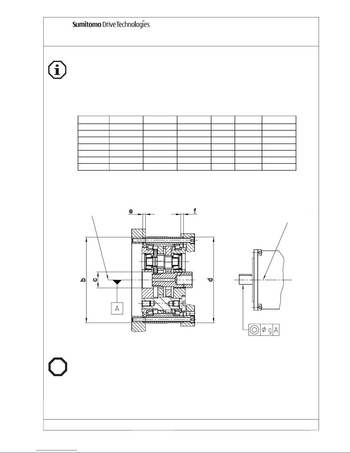
For assembly tolerances see Tab. 3.
13.7 F2C-T assembly tolerances
F2C-T
Ø b Ø c Ø d e f Ø g
155 125 H7/h7 23,5 H7/h7 125 H7/h7 8 8 0.03
255 155 H7/h7 28 H7/h/ 155 H7/h7 8 8 0.03
355 185 H7/h7 35 H7/h7 185 H7/h7 8 8 0.03
455 230 H7/h7 42 H7/h7 230 H7/h7 10 10 0.03
555 260 H7/h7 47 H7/h7 260 H7/h7 10 10 0.05
655 295 H7/h7 58 H7/h7 295 H7/h7 10 10 0.05
755 330 H7/h7 62 H7/h7 330 H7/h7 15 15 0.05
Tab. 3
Ex
The
FINE CYCLO reduction assemblies
F2C-T fulfil the requirements of guideline 94/9EU, provided
installation is in accordance with the assembly tolerances and assembly methods shown at Tab. 1 and
Tab. 2, as well as safety instructions shown in chapter 6.6, 6.7 and 7.
13.8 F2C-T
for use in hazardeous environment
Center of rotation
Center of motor
Ø
Ø
Ø
Page 34

Für Rückfragen stehen wir Ihnen
gerne zur Verfügung.
SUMITOMO (SHI) CYCLO DRIVE GERMANY, GmbH
Postfach 62, 85227 Markt Indersdorf, Germany
Tel.: +49 (0 81 36) 66-0
Fax.: +49 (0 81 36) 57 71
e-mail:[email protected]
www.sumitomodriveeurope.com
 Loading...