

Page 1

Cyclo Drive 6000
Getriebe und Getriebemotoren
Gearboxes and Gear Motors
Betriebsanleitung
Operating Manual
Nr. 991179
01/2010_2.0
Page 2

Drive 6000 Betriebsanleitung
Copyright 2012 Alle Rechte vorbehalten
Nachdruck, auch auszugsweise, ist nur mit ausdrücklicher Genehmigung von
Sumitomo (SHI) Cyclo Drive Germany GmbH (nachfolgend SCG genannt) gestattet.
Die Angaben in dieser Einbau- und Betriebsanleitung wurden mit größter Sorgfalt auf ihre Richtigkeit geprüft.
Trotzdem kann für eventuelle fehlerhafte oder unvollständige Angaben keine Haftung übernommen werden.
Technische Änderungen vorbehalten.
Inhaltsverzeichnis:
1. Allgemeine Hinweise 2
2. Hinweise zur Sicherheit 3
2.1. Sicherheitshinweise zum Einsatz im ATEX-Bereich 3
3. Hinweise zum Transport 3
4. Anbau von Übertragungselementen 4
5. Einbau des Getriebes/Getriebemotors 4
5.1 Notwendige Hilfsmittel 4
5.2 Einbautoleranzen am Getriebe/Getriebemotor 4
5.3 Prüfungen vor Beginn der Installationsarbeiten 4
5.4 Vorbereitende Arbeiten 5
5.5 Checkliste für ATEX zugelassene Getriebe vor Inbetriebnahme 5
5.6 Prüfungen vor Inbetriebnahme im Ex-Bereich 5
5.7 Aufstellung 6
6. Elektrische Installation 6
6.1 Sicherheitshinweise 6
6.2 Einsatzbereich 6
6.3 Aufstellung Motor 7
6.4 Kabeleinführungen 7
6.5 Elektrischer Anschluss 7
6.6 Bremsmotoren 8
6.7 Bremsen Verschleißprüfung 10
6.8 Umrichterbetrieb 11
6.9 Motorschutz 11
6.9.1 Fremdlüfter 11
7. Inbetriebnahme des Antriebs 11
8. Hinweise zur Schmierung 11
8.1 Fettschmierung 11
8.1.1 Lebensdauerfettschmierung 11
8.1.2 Fettschmierung mit Nachschmierung 12
8.2 Ölschmierung 12
8.2.1 Art der Ölschmierung 12
8.2.1.1 Horizontale Einbaulage 12
8.2.1.2 Vertikale Einbaulage 13
8.2.2 Empfohlene Schmieröle 14
8.2.3 Ölmengen 14
8.2.4 Ölwechselintervalle 15
9. Inspektions- und Wartungsarbeiten 15
9.1 Nachschmieren bei fettgeschmierten Getrieben 15
9.2 Ölstand prüfen 15
9.3 Öl überprüfen 15
9.4 Öl wechseln 16
10. Hinweise zu Betriebsstörungen 16
11. EG – Maschinenrichtlinie 17
12. Schnittzeichnungen 36
13. Ersatzteile Liste 39
Seite
Cyclostraße 92
85229 Markt Indersdorf
Tel. +49 (0) 8136 66 0
E-Mail: [email protected]
www.sumitomodriveeurope.com
D6000_DEU_ENG_01_2010_2.0_991179
1
Page 3
Drive 6000 Betriebsanleitung
1. Allgemeine Hinweise
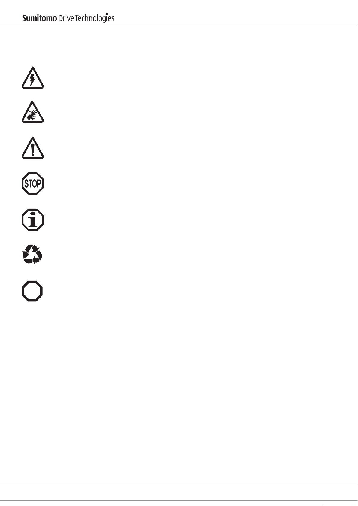
Bitte beachten Sie in dieser Dokumentation unbedingt die folgenden Sicherheitshinweise!
Gefahr durch Elektrizität
Eine falsche Anwendung der Maschine kann zu Körperschäden, ernsthaften Verletzungen und/ oder
lebensgefährlichen Situationen führen.
Gefahr
Eine falsche Anwendung der Maschine kann zu Körperschäden, ernsthaften Verletzungen und/oder
lebensgefährlichen Situationen führen.
Gefährliche Situation
Leichte Verletzungen können die Folge sein.
Schädliche Situation
Schäden am Antrieb oder an der Umgebung können die Folge sein.
Ex
Hilfreiche Informationen
Entsorgung
Bitte achten Sie auf die geltenden Bestimmungen.
Wichtige Hinweise zum Explosionsschutz ATEX
Ersatzteile
Verwenden Sie nur Original Ersatzteile. Bei der Verwendung von nicht zugelassenen
Ersatzteilen erlischt jede Gewährleistung.
2
D6000_DEU_ENG_01_2010_2.0_991179
E-Mail: [email protected]
www.sumitomodriveeurope.com
Tel. +49 (0) 8136 66 0
Cyclostraße 92
85229 Markt Indersdorf
Page 4
Drive 6000 Betriebsanleitung
2. Hinweise zur Sicherheit
Lesen Sie vor der Arbeit mit der Maschine (Montage, Betrieb, Wartung, Inspektion usw.) diese Betriebsanleitung
aufmerksam durch, so dass Sie eine genaue Kenntnis über die richtige Bedienung des
Getriebes, die anzuwendenden Sicherheitsbestimmungen und die zu beachtenden Warnhinweise haben. Bewahren Sie diese Anleitung bei der Maschine auf, so dass Sie bei Bedarf jederzeit nachschlagen können.
Transport, Montage, Schmierung, Betrieb, Wartung und Inspektion dürfen nur durch ausgebildetes technisches
Fachpersonal durchgeführt werden, andernfalls besteht die Gefahr von Verletzungen oder Schäden an der
Maschine.
Fassen Sie niemals in sich bewegende Teile und halten Sie Fremdkörper von diesen Teilen fern, andernfalls
besteht die Gefahr von Verletzungen oder Schäden an der Maschine.
Bei Wartungs- und Montagearbeiten ist die Getriebeanlage außer Betrieb zu setzen und von der
Stromzufuhr abzuklemmen.
Die Anlage darf nur für den vorgesehenen Verwendungszweck eingesetzt werden, andernfalls besteht die Gefahr von Verletzungen oder Schäden an der Maschine.
2.1. Sicherheitshinweise zum Einsatz im ATEX-Bereich
Explosionsfähige Gasgemische oder Staubkonzentrationen können in Verbindung mit heißen, spannungsführen-
Ex
den und bewegten Teilen am Getriebe schwere oder tödliche Verletzungen verursachen.
Montage, Anschluss, Inbetriebnahme sowie Wartungs- und Reparaturarbeiten am Getriebe sowie an der elektrischen Zusatzausstattung dürfen nur durch qualiziertes Fachpersonal erfolgen, unter Berücksichtigung:
- dieser Anleitung
- der Warn- und Hinweisschilder am Getriebe
- aller anderen zum Antrieb gehörenden Projektierungsunterlagen und Schaltbilder
- der anlagenspezischen Bestimmungen und Erfordernisse
- der national/regional gültigen Normen und Vorschriften (Explosionsschutz, Sicherheit, Unfallverhütung)
Die Getriebe sind für gewerbliche Anlagen bestimmt und dürfen nur entsprechend den Angaben in der technischen Dokumentation von SCG und den Angaben auf dem Typenschild verwendet werden. Sie entsprechen den
gültigen Normen und Vorschriften und erfüllen die Forderungen der Richtlinie 94/9EG.
Ein am Getriebe angeschlossener Antriebsmotor darf nur nach Sicherstellung der unter 6.3 bis 8.1 beschriebenen
Maßnahmen vor der Installation in Betrieb genommen werden.
Ein am Getriebe angeschlossener Motor darf nur am Frequenzumrichter betrieben werden, wenn die Angaben
auf dem Typenschild des Getriebes eingehalten werden!
3. Hinweise zum Transport
Die Lieferung muss sofort nach Erhalt auf etwaige Transportschäden untersucht werden, die sofort dem
Transportunternehmen mitgeteilt werden müssen. Wenn angenommen werden muss, dass ein Transportschaden den ordnungsgemäßen Betrieb einschränkt, muss die Inbetriebnahme ausgeschlossen werden.
Es dürfen nur zweckmäßige und ausreichend dimensionierte Seilschlingen, die in die ggf. vorhandenen Ringschrauben eingehängt oder um die Flanschverbindungen gelegt werden, verwendet werden. Eingeschraubte
Ringschrauben sind nur für das Gewicht des Antriebs ausgelegt. Es dürfen keine zusätzlichen Lasten angehängt
werden.
Generell gilt: Nicht die Zentrierbohrungen an den Wellenenden benutzen, um das Getriebe mittels Ringschrauben
etc. aufzuheben. Lagerschäden können die Folge sein.
Cyclostraße 92
85229 Markt Indersdorf
Tel. +49 (0) 8136 66 0
E-Mail: [email protected]
www.sumitomodriveeurope.com
D6000_DEU_ENG_01_2010_2.0_991179
3
Page 5
4. Anbau von Übertragungselementen
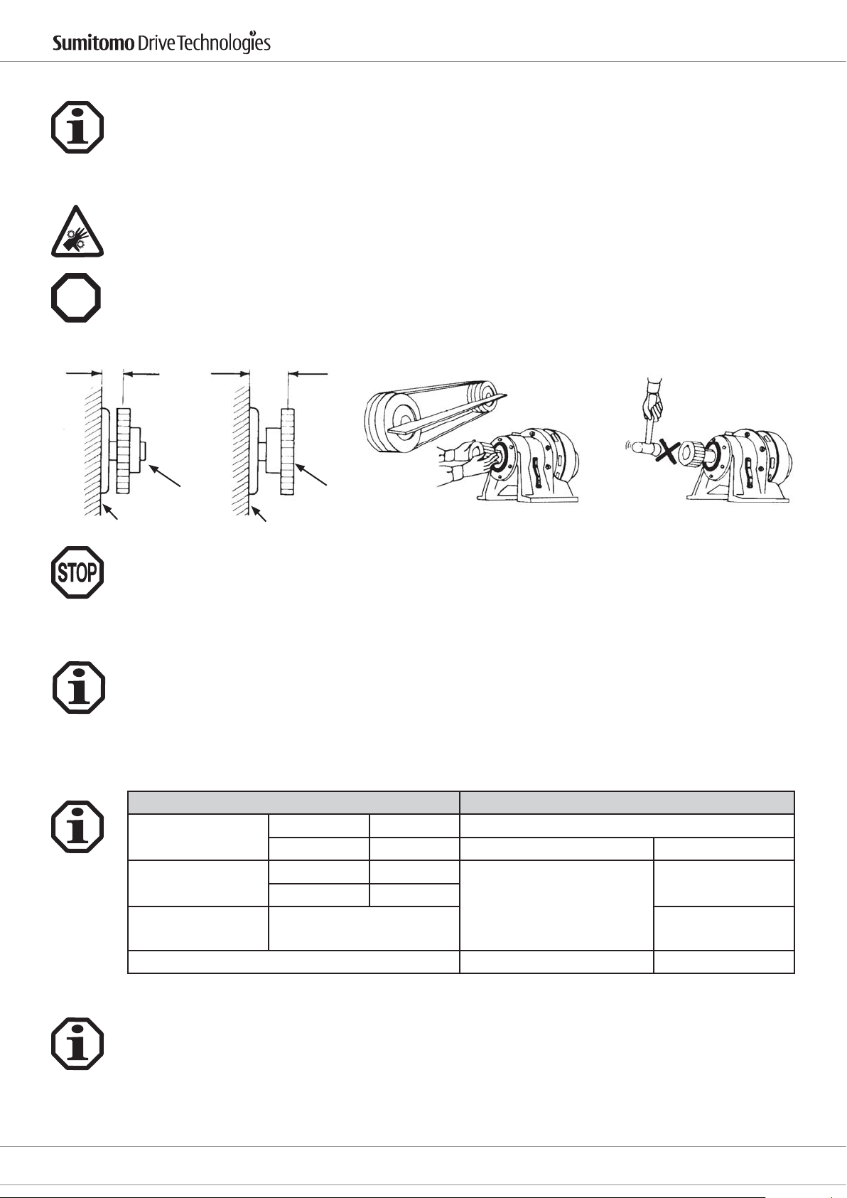
Die Montage erfolgt mit Hilfe der Zentrierbohrungen an den Wellenenden oder durch Anwärmen der aufzuziehenden Teile auf maximal 100 °C. Die Wellen sind mit einer Nut für Passfedern nach DIN 6885, Blatt 1, versehen.
Die Bohrungen von Teilen, die auf die Getriebewelle aufgesteckt werden, sollen mit den im jeweiligen Produktkatalog empfohlenen Toleranzen gefertigt werden. Zur Sicherung gegen axiales Verschieben ist eine Stellschraube
oder ähnliches anzubringen. Um die Radiallasten gering zu halten, müssen Kettenräder, Scheiben oder Zahnräder
so nahe wie möglich an das Lager gesetzt werden (s. Bild unten). Wenn die Drehmomentübertragung über Ritzel,
Kette etc. erfolgt, muss der Antrieb so eingebaut werden, dass das Getriebegehäuse auf das Fundament gedrückt
wird. Bei Getrieben mit Hohl-Antriebswelle ist auf die Motorwelle MoS2-Paste oder Spray (z.B. Molykote) aufzutragen, bevor das Gegenstück angebaut wird.
An- und Abtriebselemente wie Riemenscheiben, Kupplungen usw. müssen mit einem Berührungsschutz abgedeckt werden!
Drive 6000 Betriebsanleitung
Ex
Jegliche Anbauteile dürfen den Wärmeabuss durch Konvektion und Wärmeleitung nicht behindern.
Richtig
Riemenscheibe Riemenscheibe
Getriebe Getriebe
Kupplungen, Scheiben, Zahnräder, Ketten usw., die auf die Getriebewellen aufgesetzt werden, dürfen weder
aufgepresst noch aufgeschlagen werden, um Lagerschäden zu vermeiden.
Falsch
5. Einbau des Getriebes/Getriebemotors
5.1 Notwendige Hilfsmittel
- Schraubenschlüsselsatz
- Drehmomentschlüssel für Befestigungsschrauben an Fuß-/Flanschgehäuse, Motorlaterne,
Klemmkupplungen usw.
- Aufziehvorrichtung
- Ausgleichselemente
- Korrosionschutz (z.B. MoS2-Paste)
Rechtwinklig und parallel
Richtig Falsch
5.2 Einbautoleranzen am Getriebe/Getriebemotor
Wellen
k6 für ø < 30 mm Zentrierrandtoleranz nach DIN 42948
Antriebswellen
h6 für ø > 30 mm IEC-Flansch antriebsseitig H8
k6 für ø < 50 mm
Abtriebswellen
h6 für ø > 50 mm
Hohlwelle im
Antrieb
F7
Zentrierbohrungen nach DIN 332, Form DR Gehäuse bei F-Type g6
5.3 Prüfungen vor Beginn der Installationsarbeiten
- Übereinstimmung der Angaben auf dem Typenschild mit den vorliegenden Dokumentationen (Zeichnungen,
Stücklisten usw.)
- Übereinstimmung der Leistungsdaten des eventuell vorhandenen Motors mit dem elektrischen
Versorgungsnetz
- Der Antrieb darf keine Beschädigungen aufweisen
- Die vorgesehenen Schmierstoe müssen entsprechend den Umgebungsbedingungen passen und ggf.
bereitgestellt werden
4
D6000_DEU_ENG_01_2010_2.0_991179
E-Mail: [email protected]
www.sumitomodriveeurope.com
Flansche
Flansch abtriebsseitig
Tel. +49 (0) 8136 66 0
j6
bis Baugröße 612
f8
ab Baugröße 613
Cyclostraße 92
85229 Markt Indersdorf
Page 6
Drive 6000 Betriebsanleitung
5.4 Vorbereitende Arbeiten
Der für Transport und Lagerung verwendete Korrosionsschutz (Marke Valvoline Tectyl 846/K19) an den Wellenenden oder Hohlwellen und an den Zentriersitzen muss vor der Inbetriebnahme entfernt werden. Der Korrosionsschutz kann mit einem alkalischen Reiniger entfernt werden, auf keinen Fall jedoch mechanisch (Schleifmittel
etc.). Das alkalische Lösungsmittel darf nicht mit Dichtungen in Berührung kommen.
Beim Umgang mit Schmierstoen und Korrosionsschutzmitteln sind die Schutzvorschriften für Mensch und Umwelt gemäß den entsprechenden Sicherheitsdatenblättern nach DIN 52 900 zu beachten.
Stellen Sie sicher, dass bei der Montage des Getriebes keine explosionsfähige Atmosphäre, Öle, Säuren, Gase,
Ex
Dämpfe oder Strahlungen vorhanden sind.
Prüfen Sie, ob die Umgebungstemperatur entsprechend Kapitel 5.7 Einsatzbereich eingehalten wird.
Stellen Sie sicher, dass die Getriebe ausreichend belüftet werden und kein externer Wärmeeintrag (z. B. über
Kupplungen) vorhanden ist.
Die Kühlluft darf eine Temperatur von 40 °C nicht überschreiten.
Prüfen Sie, ob die Bauform mit der auf dem Typenschild des Getriebes angegebenen Bauform übereinstimmt.
Bitte beachten Sie: Ein Bauformenwechsel darf nur nach vorheriger Rücksprache mit SCG erfolgen, andernfalls
erlischt die ATEX-Zulassung.
Prüfen Sie bitte, ob alle zu montierenden An- und Abtriebselemente eine ATEX-Zulassung haben.
Bei Getrieben mit Adaptern ist sicherzustellen, dass die auf dem Typenschild des Getriebes angegebenen Daten
nicht überschritten werden.
Bei netzbetriebenen Motoren:
Prüfen Sie, ob die auf dem Typenschild von Getriebe und Motor angegebenen Daten mit den Umgebungsbedingungen am Einsatzort übereinstimmen.
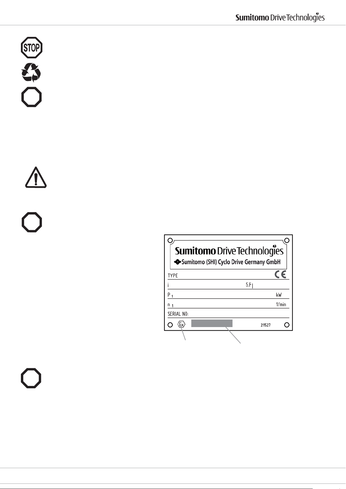
5.5. Checkliste für ATEX zugelassene Getriebe vor Inbetriebnahme
Es muss überprüft werden, ob die folgenden Angaben auf dem Typenschild des Getriebes mit
dem zulässigen Ex-Einsatzbereich vor Ort übereinstimmen:
Ex
- Gerätegruppe
- Ex-Kategorie
- Ex-Zone
- Temperaturklasse
- Maximale Oberächentemperatur
ATEX -Kennzeichnung
5.6 Prüfungen vor Inbetriebnahme im Ex-Bereich
- Entsprechen die Angaben auf dem Leistungsschild des Getriebes dem zulässigen Ex-Einsatzbereich vor Ort?
Ex
- Ist der Antrieb unbeschädigt (auf evtl. Transport- oder Lagerschäden überprüfen)?
- Ist keine explosionsfähige Atmosphäre (Öle, Säuren, Gase, Dämpfe, Strahlungen etc.) vorhanden?
- Entspricht die Bauform den Angaben auf dem Typenschild? Achtung: bei einem nicht durch
SCG vorgenommenen Bauformenwechsel erlischt die ATEX-Zulassung!
- Ist die ungehinderte Kühlluftzufuhr gewährleistet? Wird keine warme Abluft anderer Aggregate angesaugt? Die
Kühlluft darf eine Temperatur von 40 °C nicht überschreiten.
- Sind alle An- und Abtriebselemente ATEX-zugelassen?
ATEX -Klassizierung
Das Getriebe ist, falls möglich, ohne Last einzuschalten. Läuft es ruhig und ohne abnormale Geräusche, wird das
Getriebe mit der Arbeitsmaschine belastet.
Nach ca. 3 Stunden Oberächentemperatur messen. Maximal zulässiger Dierenzwert gegenüber der Umgebungstemperatur: 55 K. Bei einem Wert von >55 K Antrieb sofort stilllegen und Rücksprache mit
SHI nehmen.
Cyclostraße 92
85229 Markt Indersdorf
Tel. +49 (0) 8136 66 0
E-Mail: [email protected]
www.sumitomodriveeurope.com
D6000_DEU_ENG_01_2010_2.0_991179
5
Page 7

Bei umrichterbetriebenen Getriebemotoren:
Ex
Prüfen sie, ob der Getriebemotor für Umrichterbetrieb zugelassen ist. Die Parametrierung des Umrichters muss
eine Überlast des Getriebes verhindern (siehe Typenschild Getriebe).
5.7 Aufstellung
Der Antrieb ist so aufzustellen, dass er für eventuelle Nachschmierungen leicht zugänglich ist.
Erst nach sorgfältiger Herstellung einer einwandfrei ebenen, verwindungssteifen und schwingungsdämpfenden
Unterlage für die gesamte Anbauäche und nach Ausrichtung des Antriebs sind die Befestigungsschrauben fest
anzuziehen.
Nach ca. 4 Wochen müssen alle Befestigungsschrauben auf das richtige Anzugsmoment überprüft werden.
Wenn der Antrieb bis zum max. Abtriebsdrehmoment bzw. der max. Querkraft belastet wird, sind neben der
Fußbefestigung durch Schrauben der Festigkeitsklasse 8.8 oder höher, zusätzliche formschlüssige Verbindungen
(z.B. Zylinderstifte DIN 6325) vorzusehen.
Antriebe, die im Freien oder unter sehr ungünstigen Umgebungsbedingungen, z.B. Schmutz, Staub, Spritzwasser
oder Hitze aufgestellt werden, müssen durch eine Verkleidung geschützt werden. Dabei darf die freie Luftzufuhr
an der Gehäuseoberäche nicht beeinträchtigt werden. Ölkontroll- und Ablassschrauben sowie Atmungslter
müssen frei zugänglich sein.
Bei Gefahr von elektrochemischer Korrosion zwischen Getriebe und Arbeitsmaschine (Verbindung unterschiedlicher Metalle wie z. B. Gusseisen/Edelstahl) Zwischeneinlagen aus Kunststo verwenden (2-3 mm dick). Schrauben ebenfalls mit Unterlegscheiben aus Kunststo versehen. Gehäuse zusätzlich erden - Erdungsschrauben am
Motor verwenden.
Drive 6000 Betriebsanleitung
Für den Einsatz in Feuchträumen oder im Freien werden Antriebe in korrosionshemmender Ausführung geliefert.
Eventuell aufgetretene Lackschäden (z. B. am Entlüftungsventil) müssen nachgebessert werden.
Wird der Antrieb überlackiert bzw. teilweise nachlackiert, so ist darauf zu achten, dass das Entlüftungsventil und
die Wellendichtringe sorgfältig abgeklebt werden. Nach Beenden der Lackierarbeiten sind die Klebestreifen zu
entfernen.
Bedingungen für die Aufstellung im ATEX-Bereich
Ex
Umgebungstemperatur: -10° . . . +40 °C
Maximale Eigenerwärmung bei Nennbetrieb: 60 K
Aufstellungshöhe < = 1000 m
Maximale Antriebsdrehzahl: 1500 min
Kurzzeitige maximale Belastung: 200 % des Nenndrehmomentes
500 % Schocküberlastung ist nicht zulässig!
6. Elektrische Installation
6.1 Sicherheitshinweise
Montage, Anschluss und Inbetriebnahme sowie Wartungs- und Reparaturarbeiten dürfen nur durch qualiziertes
Fachpersonal erfolgen.
Vor Beginn jeder Arbeit am Motor oder Getriebemotor, besonders aber vor dem Önen von Abdeckungen aktiver Teile, muss der Motor vorschriftsmäßig freigeschaltet sein.
Die 5 Sicherheitsregeln nach DIN VDE 0105 sind zu beachten.
Diese Elektromotoren entsprechen den gültigen Normen und Vorschriften und erfüllen die Forderungen der
Niederspannungsrichtlinie 73/23/EWG.
Ex
Die Installation muss unter Beachtung der gültigen Vorschriften von entsprechend geschultem Fachpersonal
erfolgen.
-1
6.2 Einsatzbereich
Die Motoren sind völlig verschlossen und luftgekühlt. Standardschutzart: IP 55 mit Bremse IP 44.
Umgebungstemperatur: -10 °C bis +40 °C
Aufstellungshöhe: < 1000 m
Die Wicklung ist in Isolationsklasse F (150 °C) ausgeführt. Bei bestimmungsgemäßem Betrieb können an der
Motoroberäche Temperaturen von über 100 °C auftreten. Eine Berührung muss verhindert werden. Temperaturempndliche Teile dürfen nicht befestigt werden oder anliegen.
6
D6000_DEU_ENG_01_2010_2.0_991179
E-Mail: [email protected]
www.sumitomodriveeurope.com
Tel. +49 (0) 8136 66 0
Cyclostraße 92
85229 Markt Indersdorf
Page 8
Drive 6000 Betriebsanleitung
6.3 Aufstellung Motor
Beim Anbau von Motoren über Laterne oder IEC-Flansch muss eine entprechende IP65 geeignete Abdichtung
Ex
vorgesehen werden. Für die Ausführung dieser Abdichtung ist der Kunde verantwortlich.
Die Lüftungsönungen in der Lüfterhaube dürfen nicht verschlossen werden.
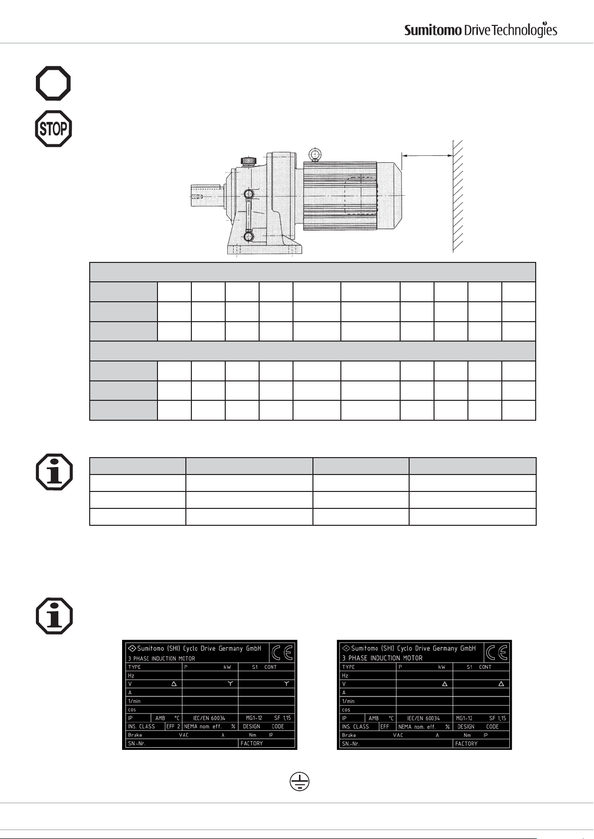
Für eine ausreichende Kühlung darf der Abstand der Haube zur Wand das Maß FB nicht unterschreiten. FA ist der
Mindestabstand, der zur Demontage der Lüfterhaube erforderlich ist.
FA oder FB
Standardmotor
Motorbaugröße
FB (mm) 20 20 20 20 20 25 30 30 30 30
FA (mm) 48 49 52 56 60 75 130 155 170 230
Motorbaugröße
FB (mm) 20 20 20 20 25 25 30 30 30 30
FA (mm) 61 93 115 121 132 170 220 367 370 445
6.4 Kabeleinführungen
Die Motoren können mit folgenden Kabeleinführungen bestückt werden:
Motor-Baugröße Kabeleinführungsgewinde Motor-Baugröße Kabeleinführungsgewinde
63-71 1 x M16 x 1,5 1 x M25 x 1,5 180 2 x M 40 x 1,5
80-132S 2x M25 x 1,5 200-225 2 x M50 x 1,5
132M-160 2 x M32 x 1,5 250 2 x M63 x 1,5
Kabelverschraubungen müssen mindestens der auf dem Typenschild angegebenen Motorschutzart genügen.
Unbenutzte Kabeleinführungen müssen entsprechend der Motorschutzart verschlossen werden. Vorhandene
Stopfen müssen fest angezogen sein.
63-71 80 90 100 112-132S 132M-160M 160L 180M 180L 220
Bremsmotor
63-71 80 90 100 112-132S 132M-160M 160L 180M 180L 220
6.5 Elektrischer Anschluss
Technische Daten sowie Angaben zu den zulässigen Einsatzbedingungen entnehmen Sie bitte dem
Leistungsschild und dieser Betriebsanleitung, sowie dem aktuellen Katalog. Angaben über Sonderausführungen
nden Sie auf Ihrer Auftragsbestätigung. Bei eventuellen Unklarheiten empfehlen wir dringend, unter Angabe
der Typenbezeichnung und der Seriennummer im Werk oder Ihrem Vertriebszentrum rückzufragen.
Motor 0,12 - 4,0 kW Motor 5,5 - 55 kW
Den Schutzleiter an dieser Klemme anschließen:
Cyclostraße 92
85229 Markt Indersdorf
Tel. +49 (0) 8136 66 0
E-Mail: [email protected]
www.sumitomodriveeurope.com
D6000_DEU_ENG_01_2010_2.0_991179
7
Page 9
Drive 6000 Betriebsanleitung
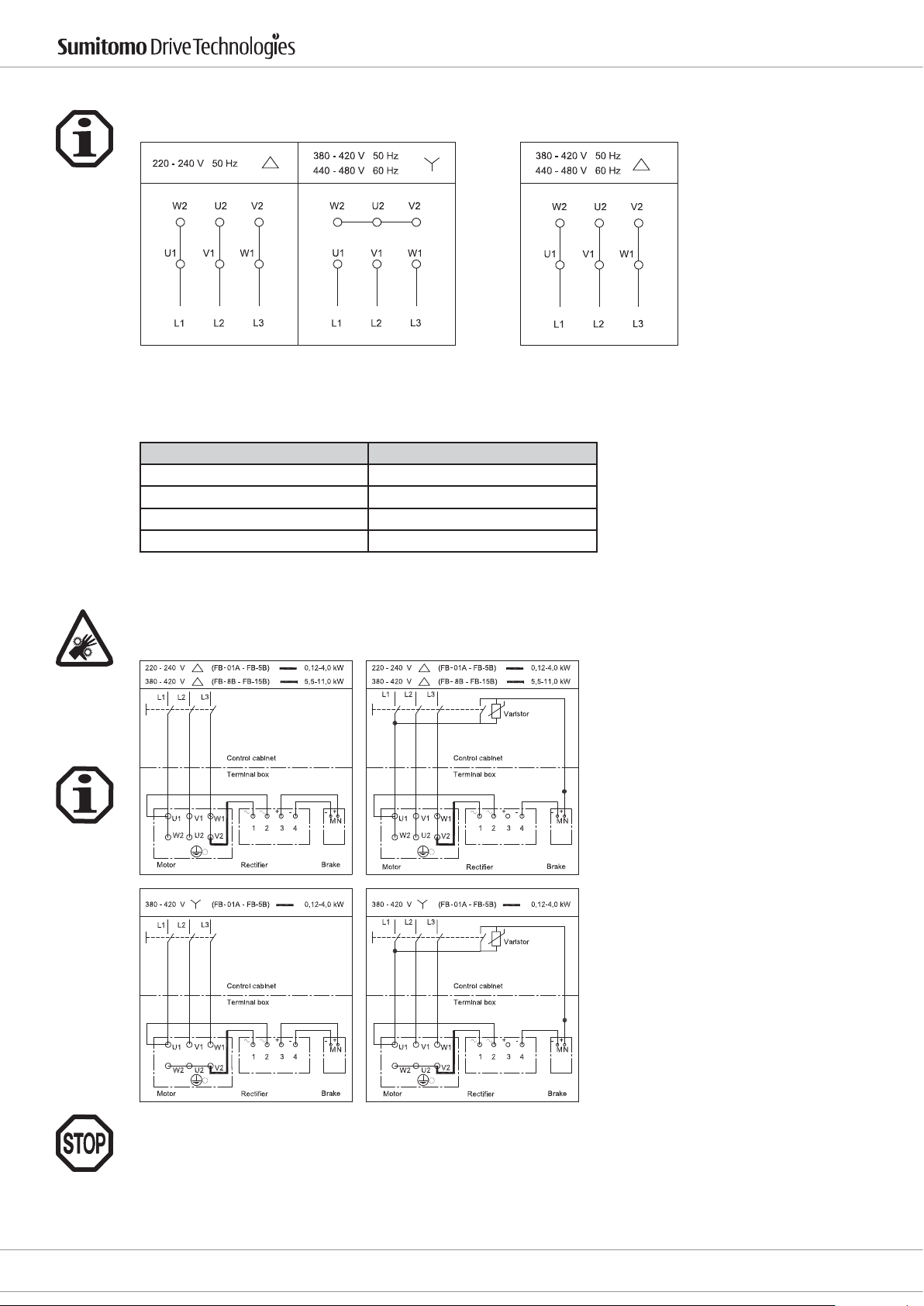
Im Klemmkasten bendet sich ein Schaltbild. Die Motoren können am Klemmbrett je nach Anschlussspannung
wie folgt geschaltet werden:
Für die angegebenen Spannungen gilt der Bemessungsspannungsbereich nach EN 60 034-1
mit ± 5 % Spannungs- oder ± 2 % Frequenzabweichung.
Für die Gewindebolzen des Klemmbrettes gelten folgende Anzugsmomente:
Bolzengewinde: Zulässiges Anzugsmoment in Nm
M4 1,2
M5 2,5
M6 4,0
M8 7,5
6.6 Bremsmotoren
Der Anschluss der Bremsmotoren erfolgt gemäß folgenden Schaltbildern:
Standard Bremse
Schnellwirkende Bremse
Die Bremssteuerspannung ist auf dem Leistungsschild vermerkt.
Wird die Halteposition der Applikation bei der Inbetriebnahme nicht erreicht, hat dies ggf. nichts mit
dem Bremsmoment zu tun.
8
D6000_DEU_ENG_01_2010_2.0_991179
E-Mail: [email protected]
www.sumitomodriveeurope.com
Tel. +49 (0) 8136 66 0
Cyclostraße 92
85229 Markt Indersdorf
Page 10
Drive 6000 Betriebsanleitung
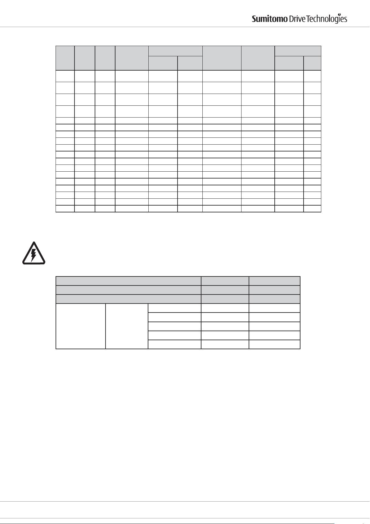
Wird nur die Wechselspannung abgeschaltet, gelten die Bremszeiten gemäß dieser Tabelle:
Bremse Reaktionszeit
standard
[sec]
schnell
[sec]
0,015 -
0,02
0,015 -
0,02
0,015 -
0,02
0,01 0,015
Bremsmotor
Trägheit
-4
kg m2]
[10
3,50 120 0,1 0,04
5,50 120 0,1 0,05
5,50 120 0,1 0,05
6,75 120 0,1 0,05
Brems Energie
6
[10
J]
Type
Brems-
Moment
[Nm]
P1
[kWxP]
0,12 x 4 FB-01A 1,0 1,3 0,15 - 0,2
0,18 x 4 FB-02A 2,0 2,7 0,15 - 0,2
0,25 x 4 FB-02A 2,0 2,7 0,15 - 0,2
0,37 x 4 FB-05A 4,0 5,4 0,1 - 0,15
0,55 x 4 FB-1D 7,5 10 0,2 - 0,3 0,01 - 0,02 11,1 330 0,1 0,1
0,75 x 4 FB-1D 7,5 10 0,2 - 0,3 0,01 - 0,02 13,0 330 0,1 0,1
1,1 x 4 FB-2D 15 20 0,2 - 0,3 0,01 - 0,02 20,8 380 0,3 0,1
1,5 x 4 FB-2D 15 20 0,2 - 0,3 0,01 - 0,02 23,5 380 0,3 0,1
2,2 x 4 FB-3D 22 30 0,3 - 0,4 0,01 - 0,02 37,3 450 0,3 0,1
3,0 x 4 FB-5B 37 50 0,4 - 0,5 0,01 - 0,02 81 2350 0,6 0,3
4,0 x 4 FB-5B 37 50 0,4 - 0,5 0,01 - 0,02 96 2350 0,6 0,3
5,5 x 4 FB-8B 55 74 0,3 - 0,4 0,01 - 0,02 125 2350 - 0,3
7,5 x 4 FB-10B 75 100 0,7 - 0,8 0,03 - 0,04 303 3430 - 0,4
11 x 4 FB-15B 110 110 0,5 - 0,6 0,03 - 0,04 410 3430 - 0,4
15 x 4 FB-20 150 220 1,7 - 1,8 0,03 - 0,06 1070 10100 - 0,5
18,5 x 4 FB-30 190 220 1,4 - 1,5 0,03 - 0,06 2430 10100 - 0,5
22 x 4 FB-30 220 220 1,4 - 1,5 0,03 - 0,06 2430 10100 - 0,5
30 x 4 FB-30 220 220 1,4 - 1,5 0,03 - 0,06 2620 10100 - 0,5
Option max.
Moment
[Nm]
Brems Strom
230 V
50 Hz
400 V
50 Hz
Wird der Gleichstromkreis nach dem Gleichrichter getrennt, fällt die Bremse bis zu 10-mal schneller ein. Dies ist
besonders für Hebezeuge wichtig.
Für eine schnelle Einfallzeit der Bremse (gleichstromseitiges Schalten) muss eine separate Leitung zu einem externen Kontakt geführt werden. Der Kontakt ist mit einem Varistor zu schützen (siehe Tabelle 2).
Tabelle 2 Spannungsbereich des Varistors
Motor Spannung AC 200-240V AC 380 - 460V
Entsprechender Bereich des Varistors AC 260-AC 300V AC 510V
Varistor Spannung 430 - 470V 820V
FB-01A, 02A, 05A > 0,2 W > 0,4 W
Entsprechende
Leistung des
Varistor
Type der
Bremse
FB-1B, 1D > 0,4 W > 0,6W
FB-2B, 3B, 2D, 3D > 0,6W > 1,5 W
FB-5B, 8B > 0,6W > 1,5 W
FB-10B, 15B > 1,0 W > 1,5 W
Cyclostraße 92
85229 Markt Indersdorf
Tel. +49 (0) 8136 66 0
E-Mail: [email protected]
www.sumitomodriveeurope.com
D6000_DEU_ENG_01_2010_2.0_991179
9
Page 11
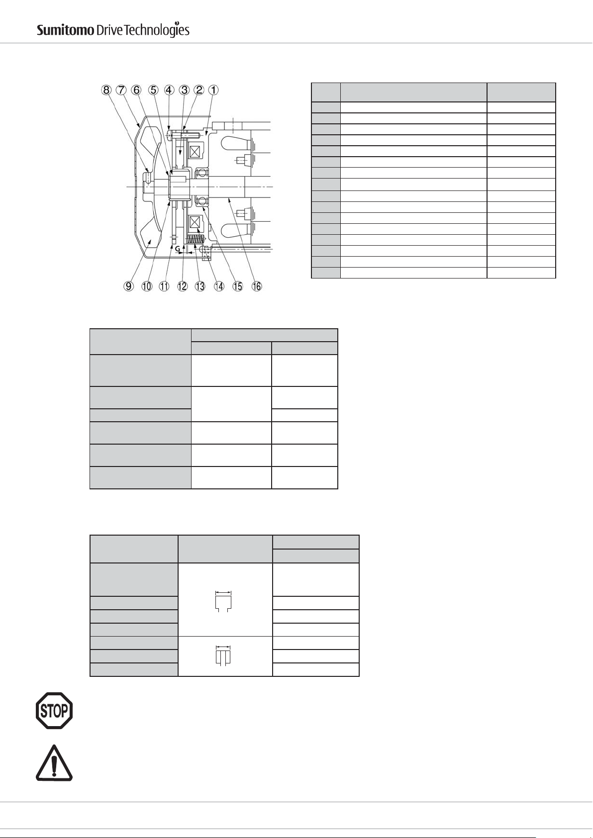
6.7 Bremsen Verschleißprüfung
Der Aufbau der Bremse ist prinzipiell im Bild unten dargestellt
Drive 6000 Betriebsanleitung
Für die FB-Bremsen gelten folgende Luftspalte:
Bremsentyp
FB-01A
FB-02A
FB-05A
FB-1B, 1D
FB-2B, 2D
FB-3B, 3D 0.7
FB-5B
FB-8B
FB-10B
FB-15B
FB-20
FB-30
Luftspalt G (mm)
Nennmaß Grenzwert
0.2~0.35 0.5
0.3~0.4
0.4~0.5 1.0
0.4~0.5 1.2
0.6~0.7 1.5
Part no
Teil Nr.
1 Stationary Statorpaket
2 Spacer Abstimmring
3 Brake lining Bremsbelag
4 Assembling bolt Schraube
5 Boss Nabe
6 Shaft retaining C-ring Sicherungsring
7 Cover Abdeckung
8 Fan set bolt Sicherungsschraube
9 Fan (Not provided for FB-01A1 and FB-01A) Lüfter
10 Leaf spring Blattfeder
11 Brake disk Bremsscheibe
12 Armature plate Ankerscheibe
13 Spring Feder
14 Electromagnetic coil Magnetspule
15 Ball bearing Kugellager
16 Motor shaft Motorwelle
0.6
Part name Name des Teils
Wird der Grenzwert des Luftspaltes überschritten, kann der Luftspalt wie in unten stehender Tabelle justiert
werden.
Type der Bremse Dicke des Bremsbelags
FB-01A
FB-02A
FB-05A
x
to
FB-1B, 1D 6.0
FB-2B, 2D 7.2
FB-3B, 3D 8.0
x
FB-5B, 8B 6
to
FB-10B, 15B 7
FB-20, 30 12
Grenzwert Dicke
x (mm)
einmalig Nachstellen
Der Luftspalt muss an mindestens drei Positionen (je 120° versetzt) geprüft werden.
Bei einer wiederholten Justage muss die Dicke des Bremsbelages geprüft werden.
Bremsen sind sicherheitsrelevante Bauteile.
Bremsbeläge und Reibscheiben werden nicht als Einzelteile verkauft.
Bremsen sind nur als kompletter Satz erhältlich.
10
D6000_DEU_ENG_01_2010_2.0_991179
E-Mail: [email protected]
www.sumitomodriveeurope.com
Tel. +49 (0) 8136 66 0
Cyclostraße 92
85229 Markt Indersdorf
Page 12
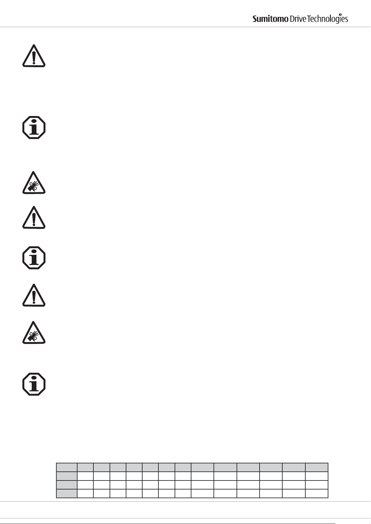
Drive 6000 Betriebsanleitung
6.8 Umrichterbetrieb
Beim Betrieb der Motoren am Frequenzumrichter sind die EMV - Hinweise des Umrichterherstellers zu beachten.
Entsprechende Entstörmaßnahmen sind zu treen. Es sollten abgeschirmte Leitungen und Kabeleinführungen
aus Metall vorgesehen werden.
Das Drehmoment des Motors hängt vom jeweiligen Umrichter ab.
Bei Bremsmotoren muss der Gleichrichter der Bremse mit einer separaten, sinusförmigen Spannung versorgt
werden.
Der Motor ist durch Kaltleiter, Thermokontakte und/oder durch Fremdlüfter vor übermäßiger Überhitzung zu
schützen.
6.9 Motorschutz
Motorschutzschalter (Überstromschutz) sind entsprechend der Spannung auf den Stromwert einzustellen, der
auf dem Leistungsschild angegeben ist.
Thermokontakte sind generell als Öner ausgeführt .
Der Widerstandswert von Kaltleitern (PTC) bei 20 °C ist nicht aussagekräftig. Der Wert kann zwischen 60 Ω und
max. 750 Ω variieren.
6.9.1 Fremdlüfter
Die Spannung und Schaltung des Fremdlüfters ist je nach Lüftertype unterschiedlich.
Der Fremdlüfter verfügt über einen separaten Klemmenkasten.
Angaben zur Spannung, Frequenz und Schaltung des Fremdlüftermotors sind in diesem Klemmenkasten.
Baugrößenabhängig sind diese unterschiedlich ausgeführt.
ACHTUNG: Je nach Steuerung kann der Fremdlüfter in Betrieb sein, auch wenn der Motor nicht dreht.
Manche Fremdlüfter können nur einphasig betrieben werden.
Andere Lüftermotoren können sowohl einphasig in Steinmetzschaltung als auch dreiphasig betrieben werden.
Drehstrommotor: In Stern- oder in Dreieckschaltung, je nach Spannung wie im Kapitel „Elektrischer Anschluss“.
7. Inbetriebnahme des Antriebs
Auf die genaue Beachtung aller Sicherheitshinweise wird nochmals ausdrücklich hingewiesen.
Netzverhältnisse und Leistungsschildangaben müssen übereinstimmen. Für Zusatzeinrichtungen, z.B. Stillstandsheizungen, sind zusätzliche Angaben im Motorklemmenkasten.
Anschlusskabel sind im Querschnitt den Motorströmen anzupassen.
Die Installation muss unter Beachtung der gültigen Vorschriften von entsprechend geschultem Fachpersonal
erfolgen.
Vor dem Einschalten des Getriebemotors ist zu überprüfen, dass alle Sicherheitsbestimmungen eingehalten werden, die Maschine ordnungsgemäß montiert und ausgerichtet ist, alle Befestigungsteile und Erdungsanschlüsse
fest angezogen sind, die Hilfs- und Zusatzeinrichtungen funktionsfähig und ordnungsgemäß angeschlossen sind
und die Passfeder eines eventuell vorhandenen zweiten Wellenendes gegen Wegschleudern gesichert ist.
Der Getriebemotor ist, falls möglich, ohne Last einzuschalten. Läuft er ruhig und ohne abnormale Geräusche,
wird der Motor mit der Arbeitsmaschine belastet. Bei der Inbetriebnahme empehlt sich eine Beobachtung der
aufgenommenen Ströme, wenn der Motor mit seiner Arbeitsmaschine belastet ist, damit mögliche Überlastungen und netzseitige Asymmetrien sofort erkennbar sind.
8. Hinweise zur Schmierung
8.1 Fettschmierung
Fettgeschmierte CYCLO Drive 6000 sind bereits ab Werk mit Fett gefüllt und werden ohne Nachfüllung in Betrieb
gesetzt. Die eingefüllte Fettsorte darf nicht mit anderen Fettsorten gemischt werden. Die Standardfette ESSO
Unirex N2 (für Lebensdauerschmierung) und Shell Alvania EP2 eignen sich für Umgebungstemperaturen von -10
°C bis +50 °C, wobei die Oberächentemperatur des Getriebes einen Wert von 950C nicht überschreiten darf. Für
einen Einsatz der Standardfette außerhalb dieses Temperaturbereiches sowie die Verwendung anderer Schmierstoe ist Rücksprache bei SCG erforderlich.
8.1.1 Lebensdauerfettschmierung
Alle CYCLO Drive 6000 Typ CN.. haben eine Lebensdauerfettschmierung und können in jeder beliebigen Position
eingebaut werden. Diese Getriebe sind werkseitig mit ESSO Unirex N2 gefüllt und benötigen keine Nachschmierung. Die Lebensdauer kann erhöht werden, wenn nach 20000 Stunden oder 4 bis 5 Jahren das Fett erneuert
wird.
Fettmengen (g) bei Erneuerung
Größe
1. Stufe
2. Stufe
Abtrieb
Cyclostraße 92
85229 Markt Indersdorf
606X 607X 608X 609X 610X 611X 612X 606XDA 607XDA 609XDA 610XDA 612XDA 612XDB
25 25 40 60 120 190 250 25 25 25 25 25 60
15 15 25 30 30 45 55 15 15 30 30 55 55
Tel. +49 (0) 8136 66 0
X = Je nach Ausführung 0 oder 5
25 25 60 120 250 250
E-Mail: [email protected]
www.sumitomodriveeurope.com
D6000_DEU_ENG_01_2010_2.0_991179
11
Page 13
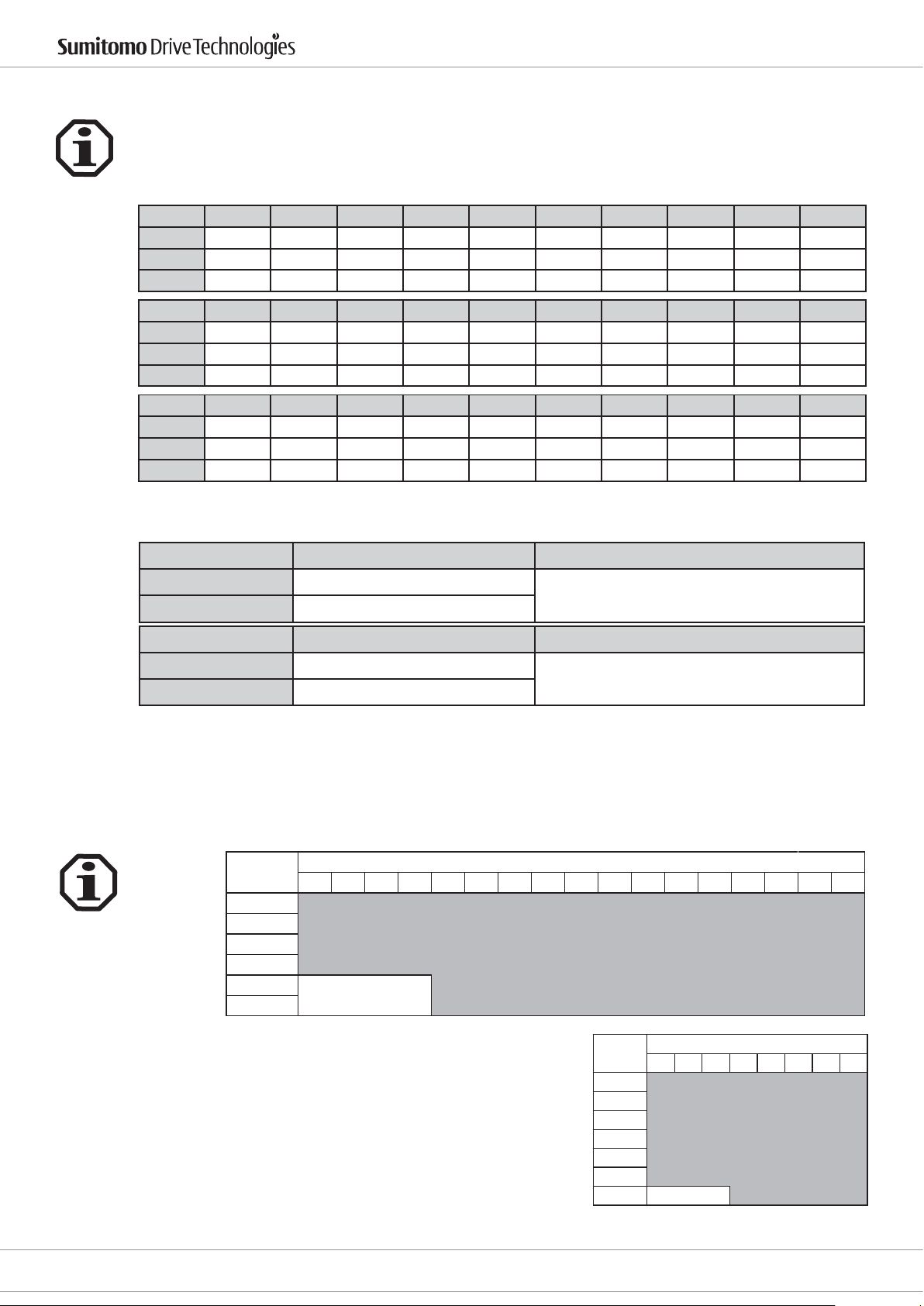
8.1.2 Fettschmierung mit Nachschmierung
CYCLO Drive 6000, die mit Esso Unirex N2 gefüllt sind, müssen nach 500 Betriebsstunden, spätestens jedoch
nach 2 Monaten, erstmals nachgeschmiert werden. Weitere Nachschmierungen entsprechend unten stehender
Tabelle:
Fettmengen (g) bei Erneuerung Bei Nachschmiermengen siehe Punkt 9.1
Größe 613XDA 613XDB 613XDC 614XDA 614XDB 614XDC 616XDA 616XDB 617XDA 617XDB
1. Stufe 25 60 120 25 60 120 60 120 60 120
2.Stufe 450 450 450 450 450 450 750 750 1000 1000
Abtrieb 300 300 300 300 300 300 300 300 500 500
Größe 618XDA 618XDB 619XDA 619XDB 6205DA 6205DB 6215DA 6215DB 6225DA 6225DB
1. Stufe 120 450 330 450 330 450 450 750 450 1000
2. Stufe 1100 1100 1500 1500 1500 1500 2000 2000 2500 2500
Abtrieb 600 600 700 700 700 700 800 800 900 900
Größe 6235DA 6235DB 6245DA 6245DB 6255DA 6255DB 6265DA - - -
1. Stufe 750 1100 750 1100 1000 1500 1500 - - -
2. Stufe 4000 4000 4500 4500 6000 6000 8000 - - -
Abtrieb 1000 1000 1100 1100 1200 1200 1300 - - -
X = Je nach Ausführung 0 oder 5
Drive 6000 Betriebsanleitung
Nachschmierungsfristen
Einsatzbedingungen Zeitpunkt zur Nachschmierung Anmerkungen
bis 10 Stunden/Tag alle 3 - 6 Monate
10 - 24 Stunden/Tag alle 500 - 1000 Stunden
Bereich Zeitpunkt des Fettwechsels Anmerkungen
Antrieb und Übersetzung alle 2 - 3 Jahre
Abtrieb alle 3 - 5 Jahre
Einfüllen und Wechsel von Schmierstoen:
CYCLO Drive 6000 ab Größe 613 sind in 2-stuger Ausführung fettgeschmiert und mit Schmiernippeln für regelmäßiges Nachschmieren ausgestattet.
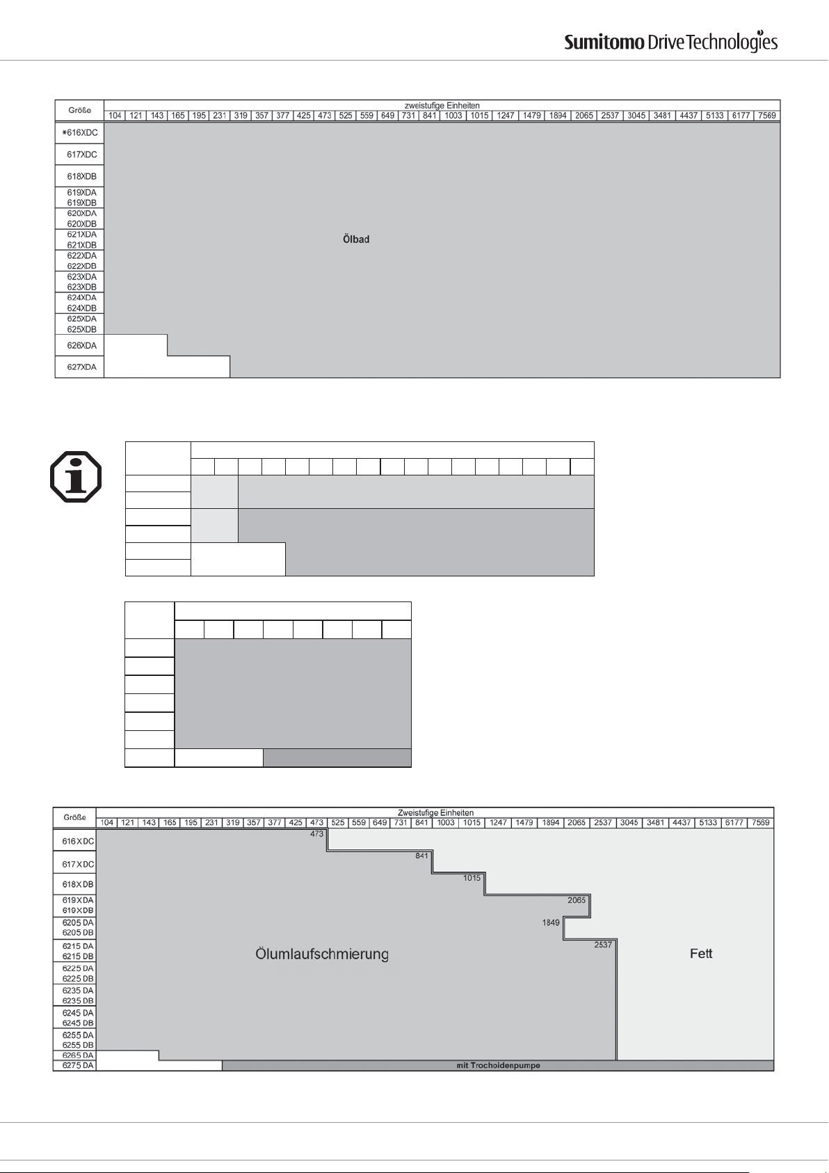
8.2 Ölschmierung
8.2.1 Art der Ölschmierung
8.2.1.1 Horizontale Einbaulage
Größe
613X
614X
616X
617X
618X
619X
X = Je nach Ausführung 0 oder 5
Bei erschwerten Betriebsbedingungen müssen die Fristen für
Bei erschwerten Betriebsbedingungen müssen die Fristen für
Nachschmierung verkürzt werden
den Fettwechsel verkürzt werden
Einstuge Einheiten
356811131517212529354351597187
Ölbad
Größe
Einstuge Einheiten
11 15 21 29 35 43 59 87
6205
6215
6225
6235
Ölbad
6245
6255
6275
12
D6000_DEU_ENG_01_2010_2.0_991179
E-Mail: [email protected]
www.sumitomodriveeurope.com
Tel. +49 (0) 8136 66 0
Cyclostraße 92
85229 Markt Indersdorf
Page 14
Drive 6000 Betriebsanleitung
X = Je nach Ausführung 0 oder 5
auch Fettschmierung möglich
*
8.2.1.2 Vertikale Einbaulage
Größe
613X
614X
616X
617X
618X
619X
X = Je nach Ausführung 0 oder 5
356811131517212529354351597187
Fett Ölbad
Fett Ölumlaufschmierung
Einstuge Einheiten
Größe
11 15 21 29 35 43 59 87
Einstuge Einheiten
6205
6215
6225
6235
Ölumlaufschmierung
6245
6255
6275 mit Trochoidenpumpe
X = Je nach Ausführung 0 oder 5
Cyclostraße 92
85229 Markt Indersdorf
Tel. +49 (0) 8136 66 0
E-Mail: [email protected]
www.sumitomodriveeurope.com
D6000_DEU_ENG_01_2010_2.0_991179
13
Page 15
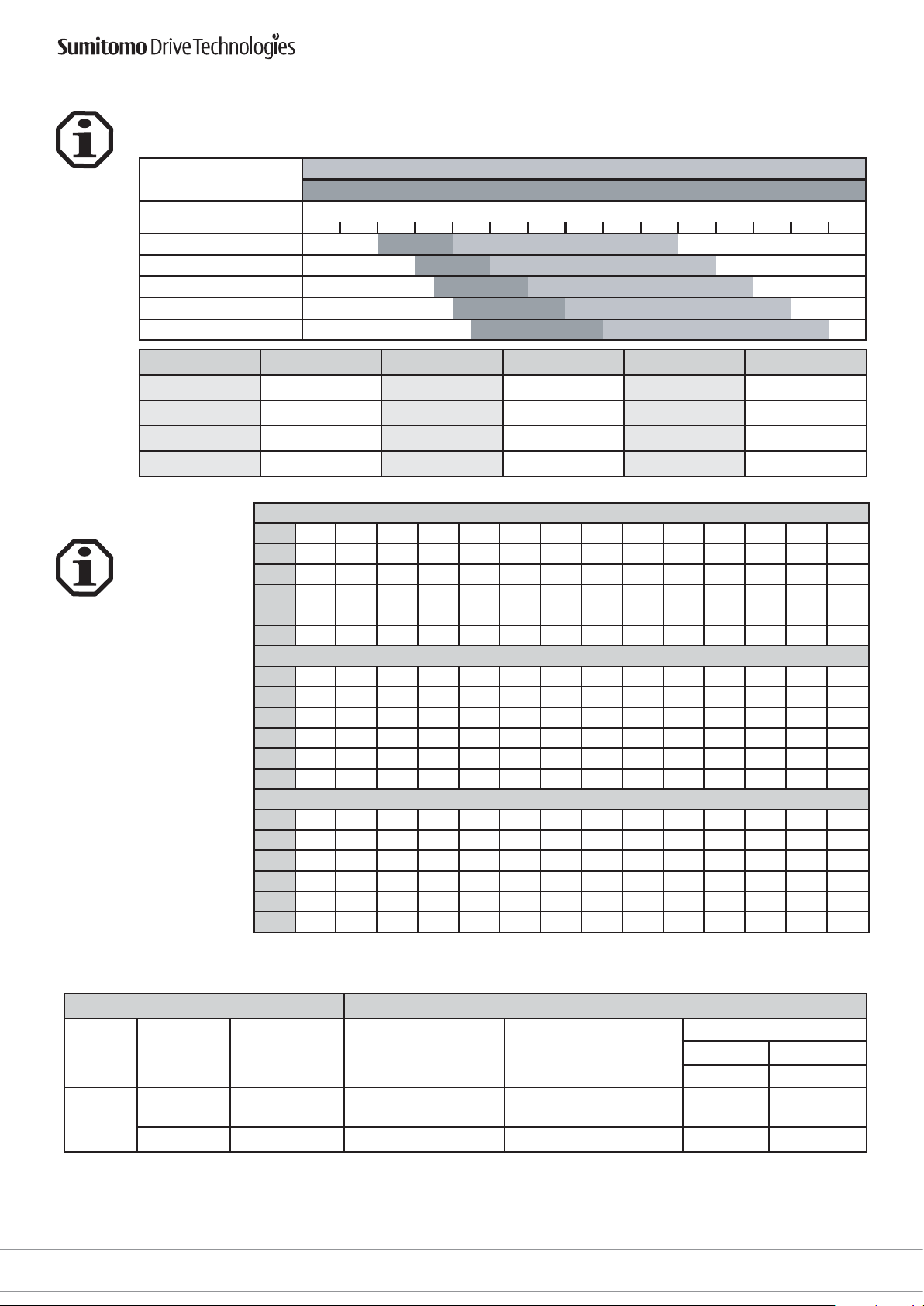
8.2.2 Empfohlene Schmieröle
Geeignet sind alle Schmieröle, die die Anforderungen nach DIN 51517 Teil 3 erfüllen.
Je nach Umgebungs- oder Betriebstemperatur muss die richtige Viskositätsklasse nach
DIN 51519 gewählt werden.
Schmierstoff nach
DIN 57517 Teil 3
CLP 68
CLP 100
CLP 150
CLP 220
CLP 320
Hersteller Marke Hersteller Marke Hersteller Marke
ARAL Degol BG DEA Falcon CLP OPTIMOL Ultra
AVIA Gear RSX ELF Reductelf SP SHELL Omala
BP Energol GR-XP KLÜBER Klüberoil GEM 1 TOTAL Carter EP
Castrol Alpha MW MOBIL Mobilgear 600XP ----- ------
Drive 6000 Betriebsanleitung
mögliche Betriebstemperaturen °C
Umgebung
-20°C 0°C +20°C +40°C +60°C +80°C +100°C
8.2.3 Ölmengen
Die angegebenen Mengen
sind durchschnittliche Richtwerte.
Die genaue Menge [l] ist
anhand des vorgeschriebenen Ölstands zu kontrollieren, zusätzlich zur Ölfördermenge der externen
Ölpumpe.
(Siehe auch Drive 6000 Katalog Kapitel Schmierung.)
CHH...., CHHX...., CHV...., CHVX....
Größe
613X 614X 616X 617X 618X 619X 6205 6215 6225 6235 6245 6255 6265 6275
0,7 0,7 1,4 1,9 2,5 4,0 5,5 8,5 10 15 16 21 29 56
[l]
Größe
616XDC 617XDC 618XDA 618XDB 619XDA 619XDB 6205DB 6205DB 6215DA 6215DB 6225DA 6225DB 6235DA 6235DB
1,5 2,4 3,5 3,5 5,8 6,0 6,0 6,0 10 10 11 11 17 17
[l]
Größe
6245DA 6245DB 6255DA 6255DB 6265DA 6275DA
18 18 23 23 32 70
[l]
CVV...., CVVX....
Größe
613X 614X 616X 617X 618X 619X 6205 6215 6225 6235 6245 6255 6265 6275
1,1 1,1 1,0 1,9 2,0 2,7 5,7 7,5 10 12 15 42 51 60
[l]
Größe
616XDC 617XDC 618XDA 618XDB 619XDA 619XDB 6205DB 6205DB 6215DA 6215DB 6225DA 6225DB 6235DA 6235DB
1,0 1,9 2,0 2,0 2,7 2,7 11 11 14 14 18 18 23 23
[l]
Größe
6245DA 6245DB 6255DA 6255DB 6265DA 6275DA
29 29 42 42 51 60
[l]
CHF...., CHFX....
Größe
613X 614X 616X 617X 618X 619X 6205 6215 6225 6235 6245 6255 6265 6275
0,250,250,91,51,323457,58111430
[l]
Größe
616XDC 617XDC 618XDA 618XDB 619XDA 619XDB 6205DB 6205DB 6215DA 6215DB 6225DA 6225DB 6235DA 6235DB
1,0 2,0 2,3 2,3 3,8 4,0 4,0 4,0 5,5 5,5 6,0 6,0 9,5 9,5
[l]
Größe
6245DA 6245DB 6255DA 6255DB 6265DA 6275DA
10 10 13 13 17 44
[l]
X = Je nach Ausführung 0 oder 5
Externe Ölpumpe (Trochoid)
Cyclo Drive Externe Ölpumpe (Trochoid)
50 Hz Bereich
Typ Baugröße Untersetzung Pumpentyp Motorpumpe
Welle
Vertikal
Achtung: Den Einsatz eines Konverters unbedingt mit dem Hersteller absprechen.
Schmierung mit der externen Ölpumpe:
Die Druckschmierung ist auf eine Verdrängerpumpe mit separater Stromversorgung ausgelegt. Um ein Anlaufen der Anlage ohne Schmierung zu
verhindern wird empfohlen den Hauptmotor mit dem Pumpenmotor so zu schalten, dass die Pumpe mind. 30 Sekunden früher startet.
14
D6000_DEU_ENG_01_2010_2.0_991179
6275
6275 DA Alle TOP 204 HA-VB3 1/2 HP (0,4 kW) 4P 6,0 16
29, 43,
59, 87
TOP 216HA-VB3 1 HP (0,75 kW) 4P 24,0 8
E-Mail: [email protected]
www.sumitomodriveeurope.com
Tel. +49 (0) 8136 66 0
'XUFKÀXVV Max. Druck
l/min Bar
Cyclostraße 92
85229 Markt Indersdorf
Page 16
Drive 6000 Betriebsanleitung
8.2.4 Ölwechselintervalle
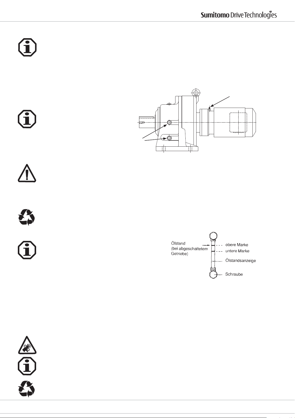
Der richtige Ölstand sollte alle 5000 Stunden überprüft werden. Wenn das Öl verschmutzt, verbrannt oder zähüssig ist, wechseln Sie das Öl sofort und spülen Sie, falls erforderlich, das Getriebe.
Unter normalen Betriebsbedingungen empfehlen wir einen Ölwechsel alle 10000 Stunden. Die Intervalle sollten
nicht länger als 2 Jahre sein. Kürzere Ölwechselintervalle (alle 3000 bis 5000 Stunden) erhöhen die Lebensdauer.
Ein Ölwechsel nach den ersten 500 Stunden ist sehr empfehlenswert.
Die oben genannten Empfehlungen können unter anderen Betriebsbedingungen wie hohe Temperatur, hohe
Feuchtigkeit oder korrosive Umgebung geändert werden. Wenn eine dieser Situationen vorliegt, müssen häugere Ölwechsel stattnden.
9. Inspektions- und Wartungsarbeiten
9.1 Nachschmieren bei fettgeschmierten Getrieben
Kontrollschraube
Die Schmierkontrollschraube am Gehäuse abschrauben und mit einer Fettpresse durch den Schmiernippel am
Flansch auf der Antriebsseite oder am Motoransch Fett nachschmieren.
Die Getriebe während des Betriebs nachschmieren, um eine gute Zirkulation des Schmierfetts sicherzustellen.
Bei jedem Nachschmieren muss ca. ein Drittel bis die Hälfte der in der Tabelle in Kapitel 8.1.2 für die 1. Stufe genannten Fettmenge nachgefüllt werden. Falls zuviel Fett nachgefüllt wird, kann es durch die Betriebserwärmung
zu einer unzulässigen Erwärmung des Schmierstos kommen, oder es kann durch Überdruck Fett in den Motor
gelangen oder zu Leckagen kommen.
Das an den Schmierkontrollschrauben ausgetretene Überschussfett sauber abwischen und fachgerecht entsorgen.
9.2 Ölstand prüfen
Der Ölstand kann an der Ölstandsanzeige überprüft werden
Schmiernippel
Bei horizontal eingebauten Getrieben bendet sich die Ölstandsanzeige normalerweise auf der rechten Seite des
Getriebes von der Abtriebswelle aus gesehen. Da die Ölstandsanzeige sowohl links als auch rechts angebracht
werden kann, ist die für das Ablesen günstigere Seite zu wählen.
Während des Betriebs gilt die untere Markierung auf der Ölstandsanzeige als Richtwert für den normalen Ölstand. Unmittelbar nach der Inbetriebnahme kann der Ölstand unter die untere rote Markierung fallen. Dies ist
jedoch nicht weiter von Bedeutung, da der Ölstand wieder ansteigt, wenn die Ölviskosität aufgrund der Betriebserwärmung abnimmt.
9.3 Öl überprüfen
· Getriebemotor spannungslos schalten, gegen unbeabsichtigtes Wiedereinschalten sichern.
· Abwarten, bis Getriebe abgekühlt ist - Verbrennungsgefahr!
· An Ölablassschraube etwas Öl entnehmen.
· Ölbeschaenheit überprüfen.
· Viskosität überprüfen.
· Zeigt das Öl visuell starke Verschmutzung wird empfohlen, außerhalb der unter
Kapitel 8.2.4 „Ölwechselintervalle“ vorgegebenen Wartungsintervalle das Öl zu wechseln.
Die entnommene Ölprobe ist fachgerecht zu entsorgen.
Cyclostraße 92
85229 Markt Indersdorf
Tel. +49 (0) 8136 66 0
E-Mail: [email protected]
www.sumitomodriveeurope.com
D6000_DEU_ENG_01_2010_2.0_991179
15
Page 17
9.4 Öl wechseln
· Getriebemotor spannungslos schalten, gegen unbeabsichtigtes Wiedereinschalten sichern.
· Abwarten, bis Getriebe abgekühlt ist - Verbrennungsgefahr!
· Ölwechsel nur bei betriebswarmem Getriebe durchführen.
· Gefäß unter Ölablassschraube stellen.
· Ölstandsanzeige, Entlüftungsschraube/-ventil und Ölablassschraube entfernen.
· Öl vollständig ablassen.
· Ölablassschraube eindrehen.
· Neues Öl entsprechend der Ölempfehlung über die Öleinfüllschraube einfüllen. Vor Verwendung anderer
Ölsorten Rücksprache mit SCG.
· Ölmenge entsprechend Kapitel 8.2.3 „Ölmengen“ einfüllen.
· An der Ölstandsanzeige überprüfen.
· Entlüftungsschraube/-ventil eindrehen.
Das abgelassene Öl ist fachgerecht zu entsorgen.
10. Hinweise zu Betriebsstörungen
Mögliche Betriebsstörungen - Fehlerursachen und Maßnahmen
Betriebsstörung Mögliche Ursache Fehlerbehebung
Drive 6000 Betriebsanleitung
Ungewöhnliche, gleichmäßige Laufgeräusche
Ungewöhnliche, ungleichmäßige
Laufgeräusche
Öl tritt aus 1)
- am Getriebedeckel
- am Motoransch
- am Motorwellendichtring
- am Getriebeansch
- am abtriebsseitigen Wellendichtring
Öl tritt aus am Entlüftungsventil
1. Geräusch abrollend/mahlend:
Lagerschaden
2. Geräusch klopfend: Unregelmäßigkeit
in der Übersetzung
Fremdkörper im Öl
1. Dichtung im Getriebedeckel undicht
2. Dichtung defekt
3. Getriebe nicht entlüftet
- zu viel Öl
- Antrieb in der falschen Bauform
eingesetzt
- häuger Kaltstart (Öl schäumt) und/
oder hoher Ölstand
1. Öl überprüfen (siehe Inspektions- und
Wartungsarbeiten), Lager wechseln
2. Kundendienst anrufen
Öl überprüfen (siehe Inspektions- und
Wartungsarbeiten)
Antrieb stillsetzen, Kundendienst anrufen
1. Schrauben am Getriebedeckel nachziehen und Getriebe beobachten. Tritt
weiter Öl aus: Kundendienst anrufen
2. Kundendienst anrufen
3. Getriebe entlüften (siehe Bauformen)
Ölmenge korrigieren (siehe Ölstand
überprüfen).
Entüftungsventil korrekt anbringen
und Ölstand korrigieren (siehe Ölstand
überprüfen).
Abtriebswelle dreht nicht, obwohl
Motor läuft oder Antriebswelle gedreht
wird
1) Am Wellendichtring in geringen Mengen austretendes Öl/Fett ist in der Einlaufphase (24 Stunden Laufzeit) als normal
anzusehen (siehe auch DIN 3761).
16
D6000_DEU_ENG_01_2010_2.0_991179
Wellen-Nabenverbindung im Getriebe
unterbrochen
E-Mail: [email protected]
www.sumitomodriveeurope.com
Getriebe/Getriebemotor zur Reparatur
einschicken
Cyclostraße 92
Tel. +49 (0) 8136 66 0
85229 Markt Indersdorf
Page 18
Drive 6000 Betriebsanleitung
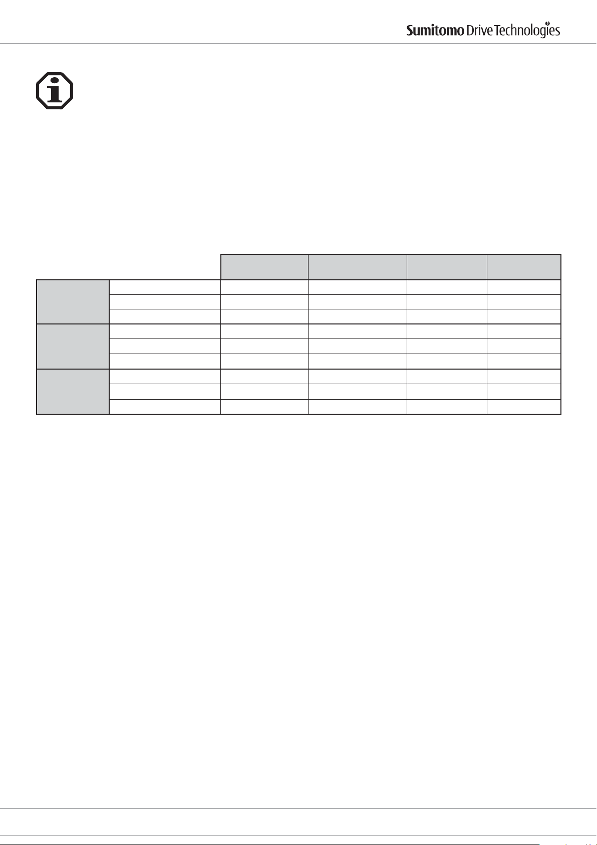
11. EG – Maschinenrichtlinie
Getriebe
Getriebe gelten als „Maschinenkomponente“ und unterliegen somit nicht der EG-Richtlinie für
Maschinen 2006/42/EG.
Im Geltungsbereich der EG-Richtlinie ist die Inbetriebnahme so lange untersagt, bis festgestellt
wurde, dass die Maschine, in der dieses Getriebe eingebaut ist, den Bestimmungen
dieser Richtlinie entspricht.
Für Getriebe werden ab 2010 keine Herstellererklärungen, EG-Konformitätserklärungen und
Einbauerklärungen mehr ausgestellt.
Getriebemotoren
Für Getriebemotoren wird eine Konformitätserklärung gemäß der Niederspannungsrichtlinie
ausgestellt.
Getriebe
Getriebemotor
Frequenzumformer
Maschinenrichtlinie
2006/42/EG
CE Kennzeichen nein nein nein ja
Konformitätserklärung nein nein nein ja
Einbauerklärung nein nein nein nein
CE Kennzeichen nein ja (auf Motor) nein ja (Getriebe)
Konformitätserklärung nein ja (auf Motor) nein ja (Getriebe)
Einbauerklärung nein nein nein nein
CE Kennzeichen nein ja (Umformer) ja nein
Konformitätserklärung nein ja (Umformer) ja nein
Einbauerklärung nein nein nein nein
Niederspannungsricht-
linie 73/23/EG
EMV 89/336/EG ATEX 94/9/EG
Cyclostraße 92
85229 Markt Indersdorf
Tel. +49 (0) 8136 66 0
E-Mail: [email protected]
www.sumitomodriveeurope.com
D6000_DEU_ENG_01_2010_2.0_991179
17
Page 19

Page 20

Drive 6000 Operating Manual
Copyright 2012 All rights reserved
Reproduction, in whole or in part, is only permitted with the express permission of Sumitomo (SHI) Cyclo Drive
Germany GmbH (here in after referred to as SCG).
The information in these installation and operating instructions have been checked very carefully for accuracy.
However, we can assume no liability for incorrect or incomplete information.
We reserve the right to make technical changes.
Contents:
1. General Notes 20
2. Safety notes 21
2.1. Safety instructions for use in an ATEX area 21
3. Notes on transport 21
4. Fitting transmission parts 22
5. Installing the gearbox/ gear motor 22
5.1 Tools required 22
5.2 Installation tolerances on the gearbox/ gear motor 22
5.3 Checks before starting installation 22
5.4 Preparatory work 23
5.5 Check list for ATEX approved gears before commissioning 23
5.6 Tests before commissioning in Ex area 23
5.7 Installation 24
6. Electrical installation 24
6.1 Safety instructions 24
6.2 Operational area 24
6.3 Installing the motor 25
6.4 Cable glands 25
6.5 Electrical connection 25
6.6 Brake motors 26
6.7 Checking for brake wear 28
6.8 Converter operation 29
6.9 Engine protection 29
6.9.1 External fans 29
7. Commissioning the input drive 29
8. Lubrication notes 29
8.1 Grease lubrication 29
8.1.1 Lifetime grease lubrication 29
8.1.2 Grease lubrication with top up lubrication 30
8.2 Oil lubrication 30
8.2.1 Type of oil lubrication 30
8.2.1.1 Horizontal installation position 30
8.2.1.2 Vertical installation position 31
8.2.2 Recommended lubrication oils 32
8.2.3 Oil quantities 32
8.2.4 Oil change intervals 35
9. Inspection and maintenance work 33
9.1 Topping up grease lubricated gearboxes 33
9.2 Checking the oil level 33
9.3 Checking the oil 33
9.4 Changing the oil 34
10. Notes on malfunctions 34
11. EC machinery directive 35
12. Construction drawing 36
13. Spare parts list 39
Page
Cyclostraße 92
85229 Markt Indersdorf
Phone +49 (0) 8136 66 0
E-Mail: [email protected]
www.sumitomodriveeurope.com
D6000_DEU_ENG_01_2010_2.0_991179
19
Page 21
1. General Notes
Please make sure that you heed the safety notes in this documentation.
Electrical hazards
Using the machine incorrectly may lead to bodily injury, serious injuries and/or life-threatening
situations.
Hazard
Using the machine incorrectly may lead to bodily injury, serious injuries and/or life-threatening
situations.
Dangerous situation
Slight injury may result.
Harmful situation
Damage to the drive or the environment could be caused.
Drive 6000 Operating Manual
Ex
Helpful information
Disposal
Please obey the regulations in force.
Important information on ATEX explosion protection
Spare parts
Only use original spare parts. Any guarantee lapses should unauthorised spare parts be used.
20
D6000_DEU_ENG_01_2010_2.0_991179
E-Mail: [email protected]
www.sumitomodriveeurope.com
Phone +49 (0) 8136 66 0
Cyclostraße 92
85229 Markt Indersdorf
Page 22
Drive 6000 Operating Manual
2. Safety notes
Before working on the machine (assembling, operating, maintaining, inspecting etc.), please read these operating
instructions through carefully so that you know exactly how to operate the gearbox properly, you know the safety
regulations to be applied and the warnings to be heeded. Keep these instructions near by the machine so that you
can refer to them at any time if necessary.
Transport, installation, lubrication, operation, maintenance and inspections should only be carried out by properly trained technicians, otherwise injury or damage to the machine may result.
Keep hands and all foreign objects away from the internal moving parts of the unit, otherwise injury or damage
to the machine may occur.
The gearbox unit must be put out of action and disconnected from the power supply for maintenance and
assembly work.
The unit must only be used for the intended purpose, otherwise there is the risk of injury or damage to the
machine.
2.1. Safety instructions for use in an ATEX area
Explosive gas mixtures or dust concentrations combined with hot, live and moving parts on the gears may cause
Ex
serious or fatal injuries.
Installing, connecting, commissioning and maintaining and repairing the gearbox and additional electrical
equipment must only be carried out by a qualied professional, taking account of
- these instructions
- the warning and instruction plates on the gearbox
- any other development documents and connection diagrams relating to the drive
- the plant-specic conditions and requirements
- the national and regional standards and regulations in force (explosion protection, safety, accident protection).
The gears are designed for industrial plants and must only be used in accordance with the information in the
technical documentation from SCG and the data on the model plate. They comply with the standards and regulations in force and meet the requirements of Directive 94/9EG.
A drive motor connected to the gearbox must only be started up after ensuring that the measures set out in 6.3 -
8.1 have been carried out before installation.
A motor connected to the gearbox may only be operated on the frequency inverter if the information on the
gearbox rating plate is obeyed.
3. Notes on transport
The consignment must be checked immediately after receipt for any transport damage. The carrier must
be notied of this immediately. If it must be assumed that transport damage will restrict proper operation
then the unit must not be started up.
Only prescribed slings of the correct size that can be hooked into the existing eyebolts or can be put round the
ange connections must be used. The screwed in eyebolts are only designed for the weight of the drive. No additional loads must be suspended.
As a general rule: Do not use the centring holes on the shaft ends to lift the gearbox by the eyebolts etc. The bearings may be damaged.
Cyclostraße 92
85229 Markt Indersdorf
Phone +49 (0) 8136 66 0
E-Mail: [email protected]
www.sumitomodriveeurope.com
D6000_DEU_ENG_01_2010_2.0_991179
21
Page 23
4. Fitting transmission parts
It is tted using the centring holes on the shaft ends or by heating the parts to be tted to a maximum of 100°C.
The shafts are tted with a groove for feather keys in accordance with DIN 6885, Sheet 1. The holes in parts that
are tted onto the gear shaft must be made with the tolerances recommended in the relevant product catalogue.
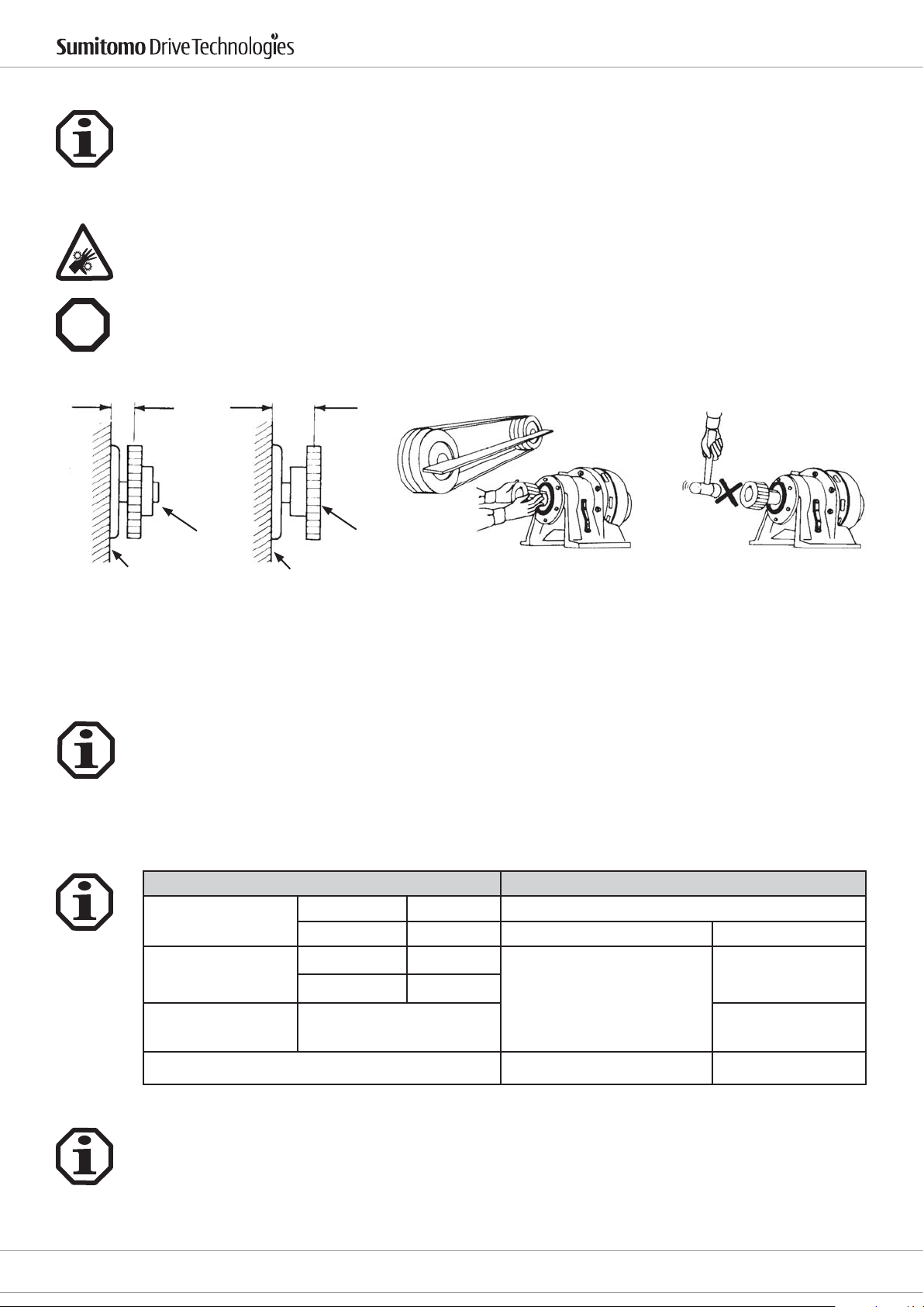
An adjusting screw or similar must be tted to prevent axial shifting. In order to keep the radial loads low, sprocket wheels, discs or gear wheels must be placed as close as possible to the bearing (see picture below). If the
torque is transferred by pinions, chains etc., the drive must be installed in such a way that the gearbox housing is
pushed onto the base-plate. With gearboxes with a hollow drive shaft, MoS2 paste or spray (e.g. molycote) must
be applied to the motor shaft before the counter part is tted.
Drive parts, such as belt pulleys, couplings etc. must be covered with a guard.
Drive 6000 Operating Manual
Ex
Any add-on parts must not obstruct the discharge of heat by convection and conduction of heat
Right
Belt pulley Belt pulley
Gearbox Gearbox
Couplings, discs, gear wheels, chains etc. that are tted to the gear shafts must not be pressed down or struck to
avoid damage to the bearings.
Wrong
5. Installing the gearbox/ gear motor
5.1 Tools required
- Spanner set
- Torque wrench for xing screws to feet/ ange housing, motor lamp, terminal couplings etc.
- Mounting device
- Compensating tools
- Corrosion protection (e.g. Mos2 paste)
Right-angled and parallel
Right Wrong
5.2 Installation tolerances on the gearbox/ gear motor
Shafts
k6 for ø < 30 mm Spigot tolerance as per DIN 42948
Drive shafts
h6 for ø > 30 mm IEC ange on the drive side H8
k6 for ø < 50 mm
Drive shafts
h6 for ø > 50 mm
Hollow shaft in
the drive
F7
Centring holes as per DIN 332, DR shape Housing for F type g6
5.3 Checks before starting installation
- Data on the model plate must agree with the existing documentation such as drawings, parts lists, etc.
- The power data of any existing motor must match that of the mains power supply.
- The drive must not be damaged in any way.
- The lubricants provided must be suitable and if necessary prepared for the environmental conditions.
22
D6000_DEU_ENG_01_2010_2.0_991179
E-Mail: [email protected]
www.sumitomodriveeurope.com
Flanges
Flange on the output side
Phone +49 (0) 8136 66 0
j6
up to size 612
f8
from size 613
Cyclostraße 92
85229 Markt Indersdorf
Page 24
Drive 6000 Operating Manual
5.4 Preparatory tasks
The anti-corrosive agent (Valvoline Tectyl 846/K19) used for transportation and storage on the shaft-ends or
hollow shafts and on the central seats must be removed before start up. The corrosion protection can be removed with an alkaline cleaner. Never use mechanical aids (abrasives etc.). The alkaline solvent must not come into
contact with gaskets.
When using lubricants, solvents and corrosion protection products, the protection guidelines for people and the
environment as set out in the corresponding DIN 52 900 safety data sheets must be heeded.
Make sure that when tting the gearbox there is no explosive atmosphere, oils, acids, gases, vapours or radiation.
Ex
Check whether the ambient temperature is within the range of application in accordance with Section 5.7
Ensure that there is enough ventilation to the gear and there is no external heat source (e. g. from couplings).
The cooling air must not exceed a temperature of 40°C.
Check that the conguration matches the conguration specied on the gear's model plate.
Please note: The design may only be changed after prior consultation with SCG, otherwise the ATEX approval will
lapse.
Please check that all drive parts to be installed are ATEX approved.
With gears with adapters, make sure that the data given on the gear's model plate is not exceeded
With mains operated motors:
Check that the data given on the gear and motor model plates matches the environmental conditions of the
installation location.
5.5. Check list for ATEX approved gears before commissioning
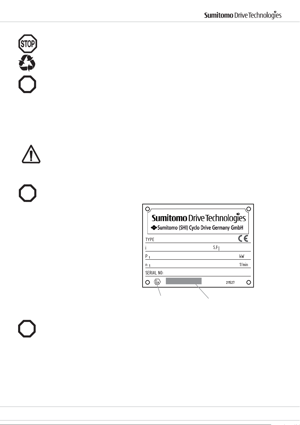
You must check whether the following data on the gear model plate agrees with the permissible explosive area on site:
Ex
- Equipment group
- Ex category
- Ex zone
- Temperature class
- Maximum surface temperature
ATEX ID
5.6 Tests before commissioning in Ex area
- Does the data on the gear box's rating plate correspond to the permissible explosive area on site?
Ex
- Is the drive undamaged? (Check for any transport or storage damage).
- Is there an explosive atomosphere (oils, acids, gases, vapours, radiation, etc.)?
- Does the design correspond to the information on the model plate? Attention: If the design has not
been changed by SCG, the ATEX approval will lapse.
- Is an unrestricted supply of cooling air guaranteed? Is any hot exhaust air being drawn in from other equiment?
The cooling air must not exceed a temperature of 40 °C.
- Are all drive parts ATEX-approved?
ATEX classication
If possible, the gear box is to be started without load. If it runs quietly and without any odd noises, the gearbox is
attached to the driven machine.
Measure the surface temperature after about 3 hours. Maximum permissible dierence from ambient temperature: 55 K. At a value of >55 K stop the drive immediately and contact
SHI.
Cyclostraße 92
85229 Markt Indersdorf
Phone +49 (0) 8136 66 0
E-Mail: [email protected]
www.sumitomodriveeurope.com
D6000_DEU_ENG_01_2010_2.0_991179
23
Page 25
With frequency inverter operated gear motors:
Ex
Check that the gear motor can be operated by a frequency inverter. The frequency inverter's parameters must be
set to prevent overloading of the gear box (see gear box model plate).
5.7 Installation
The drive must be installed so that it is easily accessible for any top up lubrication.
The xing bolts must only be tightened rmly after a perfectly level, rigid, vibration-reducing base for the whole
installation area has been carefully made and after the drive has been aligned.
After approximately 4 weeks all xing screws must be checked again to ensure they are tightened to the correct
torque.
If the drive is loaded up to the maximum output drive torque or the max. shear force, not only must the feet be
xed with screws of strength category 8.8 but also additional positive locking connections (e.g. cylindrical pins
DIN 6325) must be provided.
Drives that are installed in the open air or under very unfavourable environmental conditions, e.g. dirt, dust,
splash water or heat, must be protected by a cover. If this is done the open air feed on the housing surface must
not be adversely aected. Oil check and drain screws as well as breathing lters must be freely accessible.
If there is the risk of electrochemical corrosion between the gearbox and the driven machine (combination of
dierent metals, such as cast iron/ stainless steel) use plastic intermediate layers (2 - 3 mm thick). Also t screws
with plastic washers. Also earth the housing. Use earthing screws on the motor.
Drive 6000 Operating Manual
A corrosion-inhibiting version of the drive is available for use in moisture-prone areas or in the open air. Any paint
damage that occurs (e.g. on the bleed valve) must be touched up.
If the drive is painted or partially re-painted you must ensure that the bleed valve and the shaft seal rings are
masked carefully. After you have nished painting the adhesive strips must be removed.
Conditions for installing in an ATEX area
Ex
Ambient temperature: -10° . . . +40° C
Maximum self-heating at nominal rating: 60 K
Installation height < = 1000 m
Maximum drive speed: 1500 min
Short term maximum load: 200 % of the rated load torque
500 % shock overload is not permitted.
6. Electrical installation
6.1 Safety notes
Installation, connection and commissioning work as well as maintenance and repairs must only be carried out by
qualied experts.
Before any work starts on the motor or the gear motor but particularly before covers are taken o active parts,
the motor must be disconnected as prescribed.
The 5 safety rules as set out in DIN VDE 0105 must be obeyed.
These electric motors comply with the standards and regulations in force and meet the requirements of the Low
Voltage Directive 73/23/EWG.
-1
Ex
The installation is subject to all regulations in force and must be done by qualied personnel.
6.2 Area of application
The motors are completely sealed and air-cooled. Standard protection type: IP 55 with IP 44 brake.
Ambient temperature: -10°C to +40°C
Installation height: < 1000 m
The coil is designed to be in insulation class F (150 °C). If operated properly the temperatures on the motor surface
may reach more than 100 °C. Do not touch. Temperature-sensitive parts must not be xed on or rest against it.
24
D6000_DEU_ENG_01_2010_2.0_991179
E-Mail: [email protected]
www.sumitomodriveeurope.com
Phone +49 (0) 8136 66 0
Cyclostraße 92
85229 Markt Indersdorf
Page 26
Drive 6000 Operating Manual
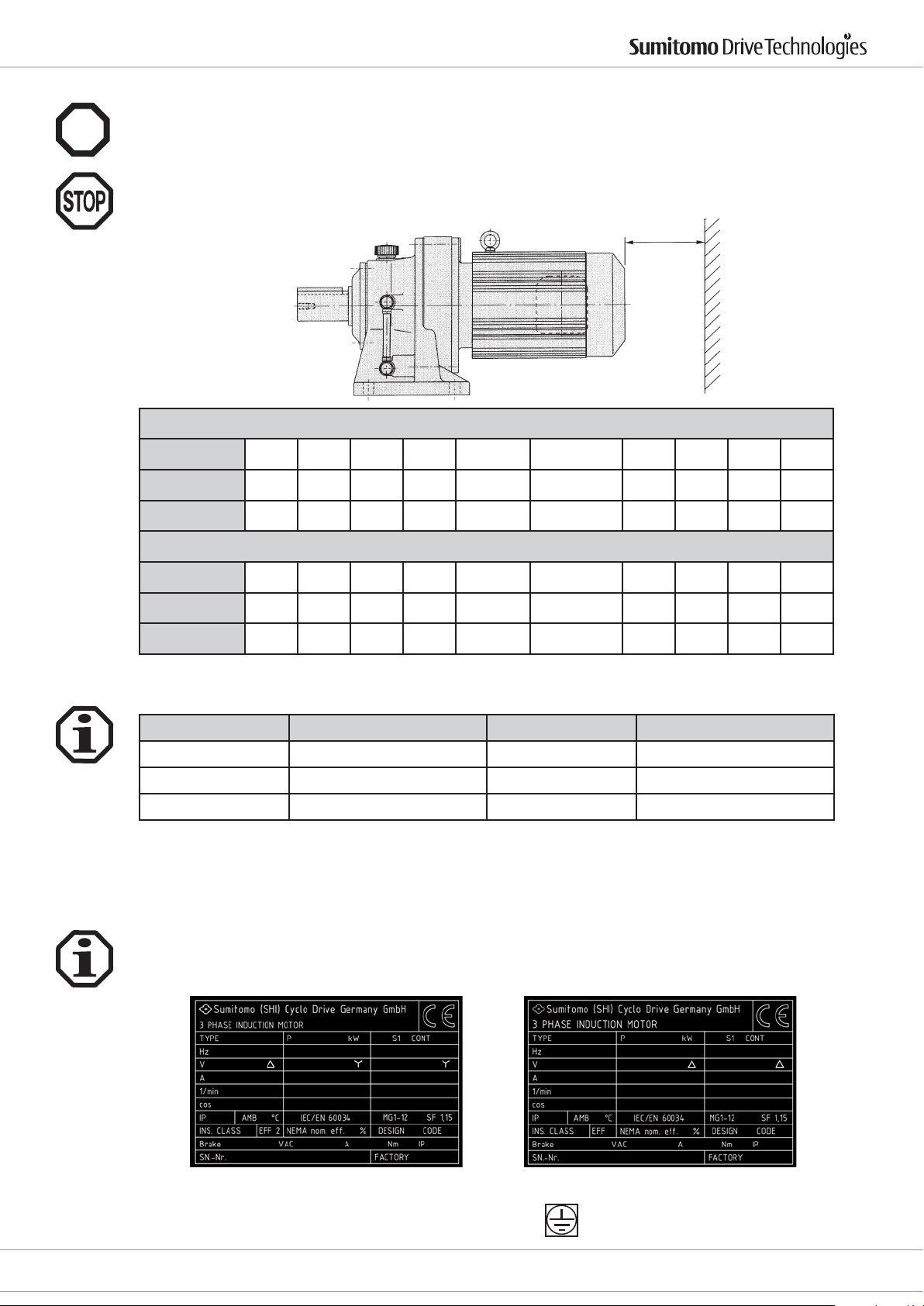
6.3 Installing the motor
When connecting motors via brackets or an IEC ange, a suitable IP65 seal must be provided. The customer is
Ex
responsible for tting this seal.
The ventilation openings in the fan hood must not be blocked.
For sucient cooling, the distance between the hood and the wall must not fall below the FB measurement. FA is
the minimum distance required to remove the fan hood.
FA or FB
Standard motor
Motor size
FB (mm) 20 20 20 20 20 25 30 30 30 30
FA (mm) 48 49 52 56 60 75 130 155 170 230
Motor size
FB (mm) 20 20 20 20 25 25 30 30 30 30
FA (mm) 61 93 115 121 132 170 220 367 370 445
6.4 Cable glands
Motors can be tted with the following cable entry points:
Cable glands must comply at least with the motor protection class specied on the model plate.
Unused cable glands must be closed depending on the type of motor protection. Existing plugs must be tightened rmly.
63-71 80 90 100 112-132S 132M-160M 160L 180M 180L 220
Brake motor
63-71 80 90 100 112-132S 132M-160M 160L 180M 180L 220
Frame Conduit threat Frame Conduit threat
63-71 1 x M16 x 1,5 1 x M25 x 1,5 180 2 x M 40 x 1,5
80-132S 2x M25 x 1,5 200-225 2 x M50 x 1,5
132M-160 2 x M32 x 1,5 250 2 x M63 x 1,5
6.5 Electrical connection
Please refer to the rating plate and these operating instructions as well as the current catalogue for technical data
and information on the permissible operating conditions. You will nd information on special versions on your
order conrmation. If anything is unclear, we urgently recommend you to contact the factory or your sales centre
giving the model description and the serial number.
Motor 0.12 - 4.0 kW Motor 5.5 - 55 kW
Connect the protective earthing conductor to this terminal.
Cyclostraße 92
85229 Markt Indersdorf
Phone +49 (0) 8136 66 0
E-Mail: [email protected]
www.sumitomodriveeurope.com
D6000_DEU_ENG_01_2010_2.0_991179
25
Page 27
Drive 6000 Operating Manual
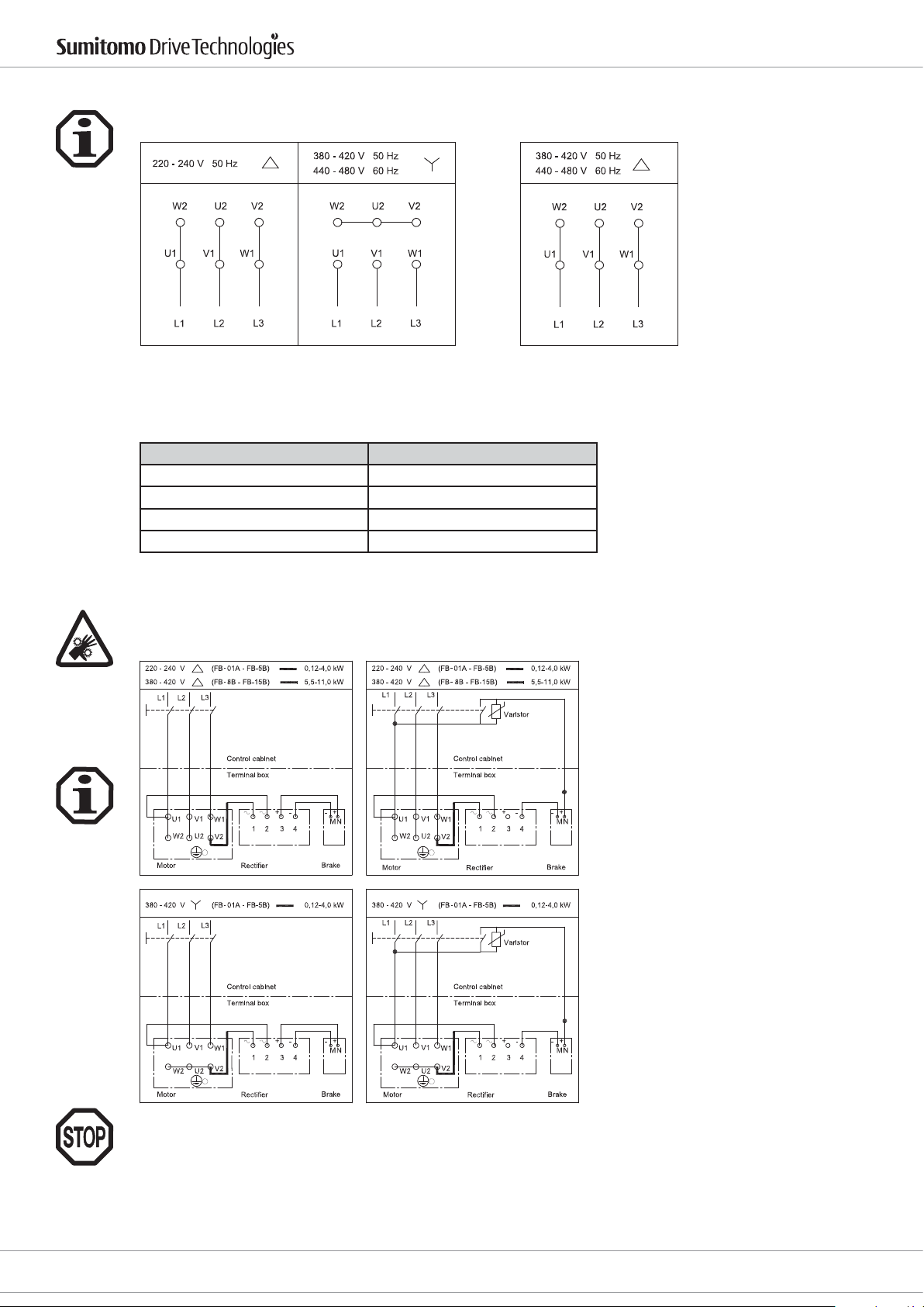
A circuit diagram is located in the terminal box. The motors can be connected to the terminal board depending
on the connection voltage as follows:
The rated voltage range as set out in EN 60 034-1 applies to the specied voltages with a ± 5 % voltage or ± 2 %
frequency deviation.
The following tightening torques apply to the threaded bolts on the terminal board:
Screw thread: Permissible tightening torque in Nm
M4 1.2
M5 2.5
M6 4.0
M8 7.5
6.6 Brake motors
The brake motors are connected in accordance with the following circuit diagrams:
Standard brake
Rapid action brake
26
The brake control voltage is noted on the rating plate.
If the stop position of the application is not reached on starting up, this may not have anything to do with
the brake torque.
Cyclostraße 92
85229 Markt Indersdorf
D6000_DEU_ENG_01_2010_2.0_991179
E-Mail: [email protected]
www.sumitomodriveeurope.com
Phone +49 (0) 8136 66 0
Page 28
Drive 6000 Operating Manual
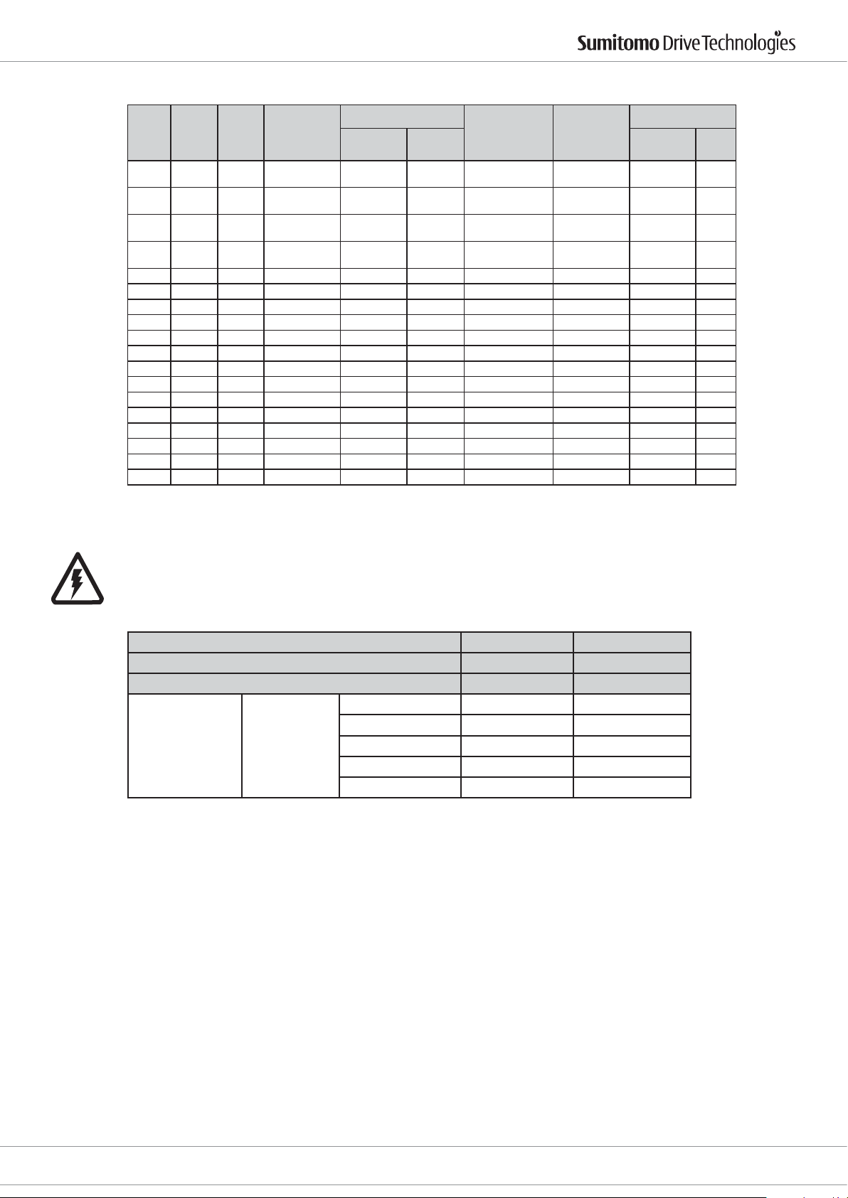
If only the alternating current is switched o, the braking times as set out in the table below apply.
P1
[kWxP]
0.12 x 4 FB-01A 1.0 1.3 0.15 - 0.2
0.18 x 4 FB-02A 2.0 2.7 0.15 - 0.2
0.25 x 4 FB-02A 2.0 2.7 0.15 - 0.2
0.37 x 4 FB-05A 4.0 5.4 0.1 - 0.15
0.55 x 4 FB-1D 7.5 10 0.2 - 0.3 0.01 - 0.02 11.1 330 0,1 0,1
0.75 x 4 FB-1D 7.5 10 0.2 - 0.3 0.01 - 0.02 13.0 330 0,1 0,1
1.1 x 4 FB-2D 15 20 0.2 - 0.3 0.01 - 0.02 20.8 380 0,3 0,1
1.5 x 4 FB-2D 15 20 0.2 - 0.3 0.01 - 0.02 23.5 380 0,3 0,1
2.2 x 4 FB-3D 22 30 0.3 - 0.4 0.01 - 0.02 37.3 450 0,3 0,1
3.0 x 4 FB-5B 37 50 0.4 - 0.5 0.01 - 0.02 81 2350 0,6 0,3
4.0 x 4 FB-5B 37 50 0.4 - 0.5 0.01 - 0.02 96 2350 0,6 0,3
5.5 x 4 FB-8B 55 74 0.3 - 0.4 0.01 - 0.02 125 2350 - 0,3
7.5 x 4 FB-10B 75 100 0.7 - 0.8 0.03 - 0.04 303 3430 - 0,4
11 x 4 FB-15B 110 110 0.5 - 0.6 0.03 - 0.04 410 3430 - 0,4
15 x 4 FB-20 150 220 1.7 - 1.8 0.03 - 0.06 1070 10100 - 0,5
18.5 x 4 FB-30 190 220 1.4 - 1.5 0.03 - 0.06 2430 10100 - 0,5
22 x 4 FB-30 220 220 1.4 - 1.5 0.03 - 0.06 2430 10100 - 0,5
30 x 4 FB-30 220 220 1.4 - 1.5 0.03 - 0.06 2620 10100 - 0,5
Type
Brake
torque
[Nm]
Optional max.
torque
[Nm]
Brake reaction time
standard
[sec]
0.015 -
0.015 -
0.015 -
fast
[sec]
0.02
0.02
0.02
0.01 -
0.015
Brake motor
inertia
-4
kg m2]
[10
3.50 120 0,1 0,04
5.50 120 0,1 0,05
5.50 120 0,1 0,05
6.75 120 0,1 0,05
Brake energy
6
[10
J]
Brake power
230 V
50 Hz
400 V
50 Hz
If the direct current circuit is cut o after the rectier, the brake is applied up to 10 times faster. This is particularly
important for lifting devices.
To ensure that the brake (connected to the DC side) is applied quickly, a separate cable must be run to an external contact. The contact must be protected by a Varistor
(see Table 2).
Table 2 Varistor voltage range
Motor voltage AC 200-240V AC 380 - 460V
Corresponding Varistor range AC 260-AC 300V AC 510V
Varistor voltage 430 - 470V 820V
FB-01A, 02A, 05A > 0.2 W > 0.4 W
Corresponding
Varistor output
Type of brakes
FB-1B, 1D > 0.4 W > 0.6W
FB-2B, 3B, 2D, 3D > 0.6W > 1.5 W
FB-5B, 8B > 0.6W > 1.5 W
FB-10B, 15B > 1.0 W > 1.5 W
Cyclostraße 92
85229 Markt Indersdorf
Phone +49 (0) 8136 66 0
E-Mail: [email protected]
www.sumitomodriveeurope.com
D6000_DEU_ENG_01_2010_2.0_991179
27
Page 29
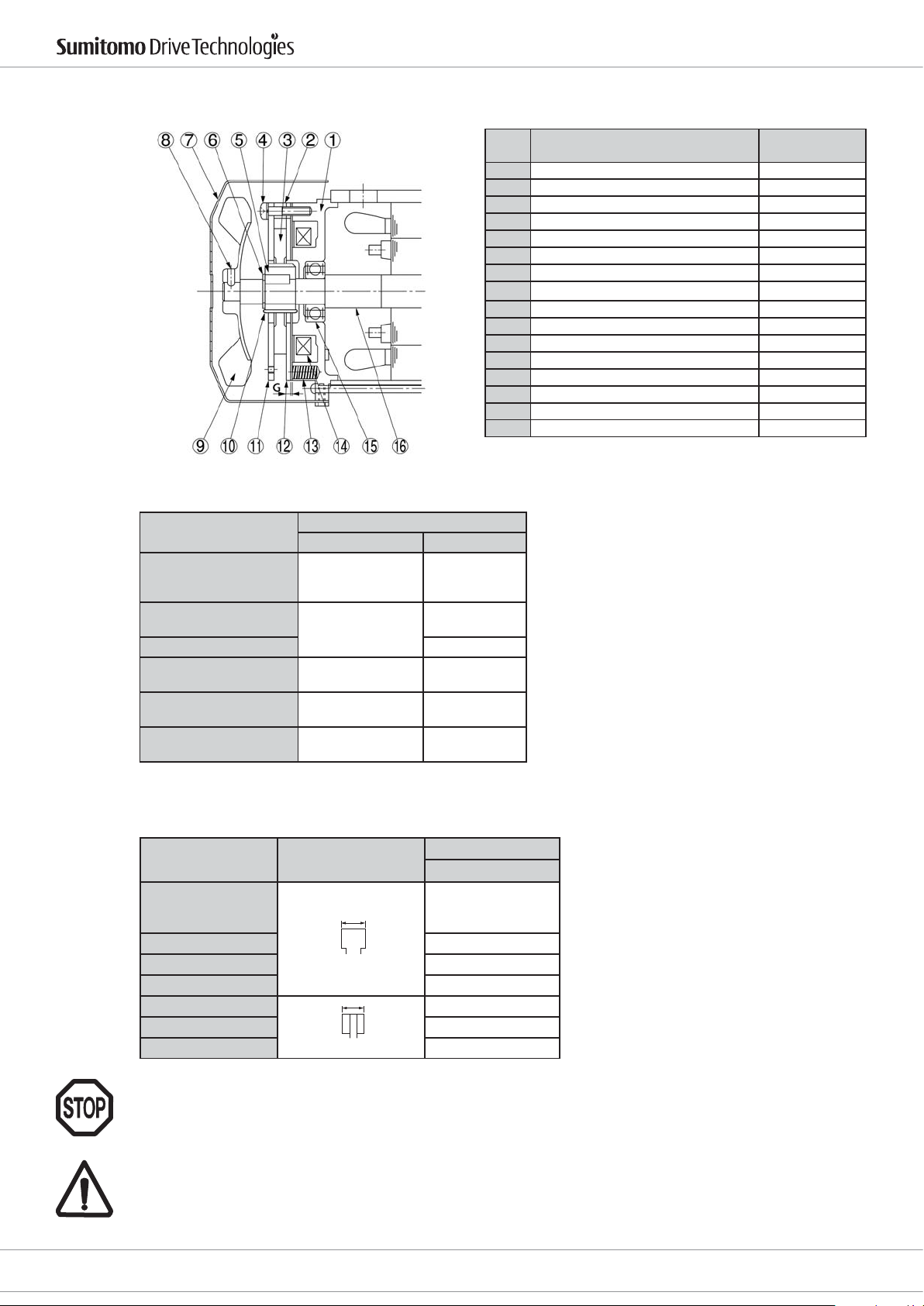
6.7 Checking for brake wear
The brake is normally assembled as shown in the picture below.
Drive 6000 Operating Manual
The following air gaps apply to the FB brakes:
Type of brake
FB-01A
FB-02A
FB-05A
FB-1B, 1D
FB-2B, 2D
FB-3B, 3D 0.7
FB-5B
FB-8B
FB-10B
FB-15B
FB-20
FB-30
Nominal dimensions Limit
Air gap G (mm)
0.2~0.35 0.5
0.3~0.4
0.4~0.5 1.0
0.4~0.5 1.2
0.6~0.7 1.5
Part no
Teil Nr.
1 Stator packet Statorpaket
2 Spacer Abstimmring
3 Brake lining Bremsbelag
4 Assembling bolt Screw
5 Boss Nabe
6 Shaft retaining C-ring Lock washer
7 Cover Abdeckung
8 Fan set bolt Sicherungsschraube
9 Fan (Not provided for FB-01A1 and FB-01A) Lüfter
10 Leaf spring Blattfeder
11 Brake disk Bremsscheibe
12 Armature plate Ankerscheibe
13 Spring Feder
14 Electromagnetic coil Magnetspule
15 Ball bearing Kugellager
16 Motor shaft Motorwelle
0.6
Part name Name des Teils
If the air gap limit is exceeded it can be adjusted as set out in the table below.
Type of brakes
Thickness of brake
lining
FB-01A
FB-02A
FB-05A
x
to
FB-1B, 1D 6.0
FB-2B, 2D 7.2
FB-3B, 3D 8.0
x
FB-5B, 8B 6
to
FB-10B, 15B 7
FB-20, 30 12
Thickness limit
x (mm)
one-off adjustment
The air gap must be checked at at least three positions (each oset to 120).
If the adjustment is repeated the thickness of the brake lining must be checked.
Brakes are safety-related components.
Brake liners and friction discs are not sold as separate parts.
Brakes are only available as a complete set.
28
D6000_DEU_ENG_01_2010_2.0_991179
E-Mail: [email protected]
www.sumitomodriveeurope.com
Phone +49 (0) 8136 66 0
Cyclostraße 92
85229 Markt Indersdorf
Page 30
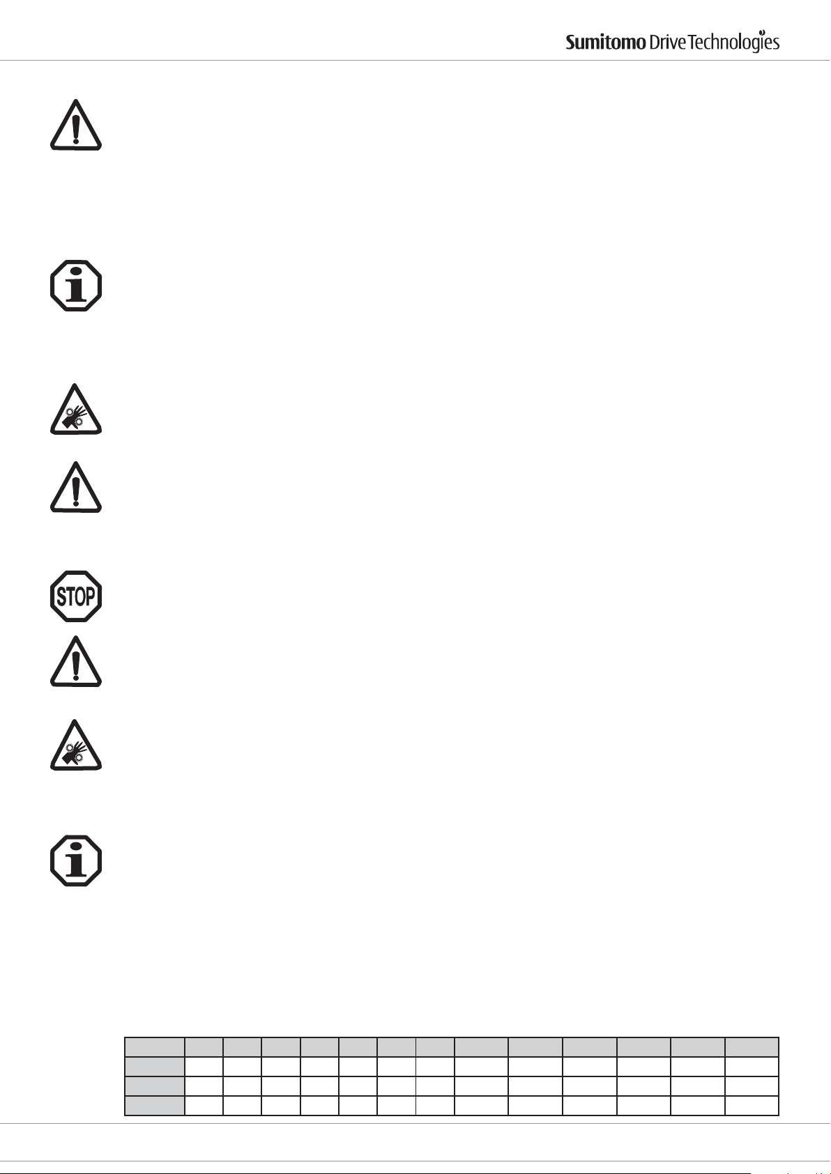
Drive 6000 Operating Manual
6.8 Converter operation
When operating the motors on the frequency converter the converter manufacturer's EMC notes must be
observed. Appropriate suppression measures must be taken. Metal shielded cables and cable glands should be
provided.
The motor's torque depends on the respective converter.
With brake motors the brake's rectier must be tted with a separate, sinusoid voltage.
The motor must be protected from excessive overheating by cold conductors, thermo contacts and/ or by external fans.
6.9 Motor protection
Motor protection switches (overload protection) must be set to the current value specied on the rating plate
depending on the voltage.
Thermo contacts are normally designed as openers.
The resistance of cold conductors (PTC's) at 20 °C is not signicant. The value may vary between 60 Ω and a maximum of 750 Ω.
6.9.1 External fans
The voltage and wiring of the external fan are dierent depending on the type of fan.
The external fan has a separate terminal box.
Information on the voltage, frequency and wiring of the external fan is in this terminal box. These are dierent
depending on the size.
ATTENTION : Depending on the controls, the external fan may operate even if the motor is not turning.
Some external fans can only be operated in single phase.
Other fan motors can be operated both in single phase in a Steinmetz circuit and also in triphase.
3 phase motor: In a star circuit or a triangular circuit, depending on the voltage as in the section "Electrical connection".
7. Commissioning the input drive
Ensure that all safety instructions have been explicitly obeyed once more.
Mains power conditions and the information on the rating plate must be the same. There is additional information in the motor terminal box for additional equipment, such as standstill heating.
The cross section of the connection cables must be adapted to the motor currents.
The installation is subject to all regulations in force and must be done by qualied personnel.
Before starting the gear motor, ensure that all safety regulations have been obeyed, the machine has been
installed and aligned properly, all fastenings and earth connections have been tightened properly, the auxiliary
and additional devices are working properly and have been connected properly and that the feather key on any
second shaft end key cannot be ung out.
If possible, the gear box is to be started without load. If it runs quietly and without any odd noises, the motor is
attached to the driven machine. On starting up it is advisable to look at the currents being used when the motor
is connected to its driven machine so that potential overloads and asymmetries on the mains side can be detected immediately.
8. Lubrication notes
8.1 Lubrication
Grease lubricated CYCLO Drive 6000's are already lled with grease at the factory and are operated without topping up. The type of grease used must not be mixed with other types of grease. The standard ESSO Unirex N2 grease (for lifetime lubrication) and Shell Alvania EP2 grease are suitable for ambient temperatures of between -10 °C
and +50 °C though the maximum surface temperature of the drive housing must not exeed 950C. Please contact
SCG if you wish to use standard greases outside this temperature range or if you wish to use other lubricants.
8.1.1 Lifetime grease lubrication
All type CN CYCLO Drive 6000's .. are greased for life and can be installed in any position. These gearboxes are
lled at the factory with ESSO Unirex N2 and do not need topping up. The lifetime can be increased if the grease
is replaced after 20000 hours or between 4 - 5 years.
Grease quantities (g) when replacing
Size 606X 607X 608X 609X 610X 611X 612X 606XDA 607XDA 609XDA 610XDA 612XDA 612XDB
1st stage 25 25 40 60 120 190 250 25 25 25 25 25 60
2nd stage 25 25 60 120 250 250
Output 15 15 25 30 30 45 55 15 15 30 30 55 55
X = Means type 0 oder 5
Cyclostraße 92
85229 Markt Indersdorf
Phone +49 (0) 8136 66 0
E-Mail: [email protected]
www.sumitomodriveeurope.com
D6000_DEU_ENG_01_2010_2.0_991179
29
Page 31
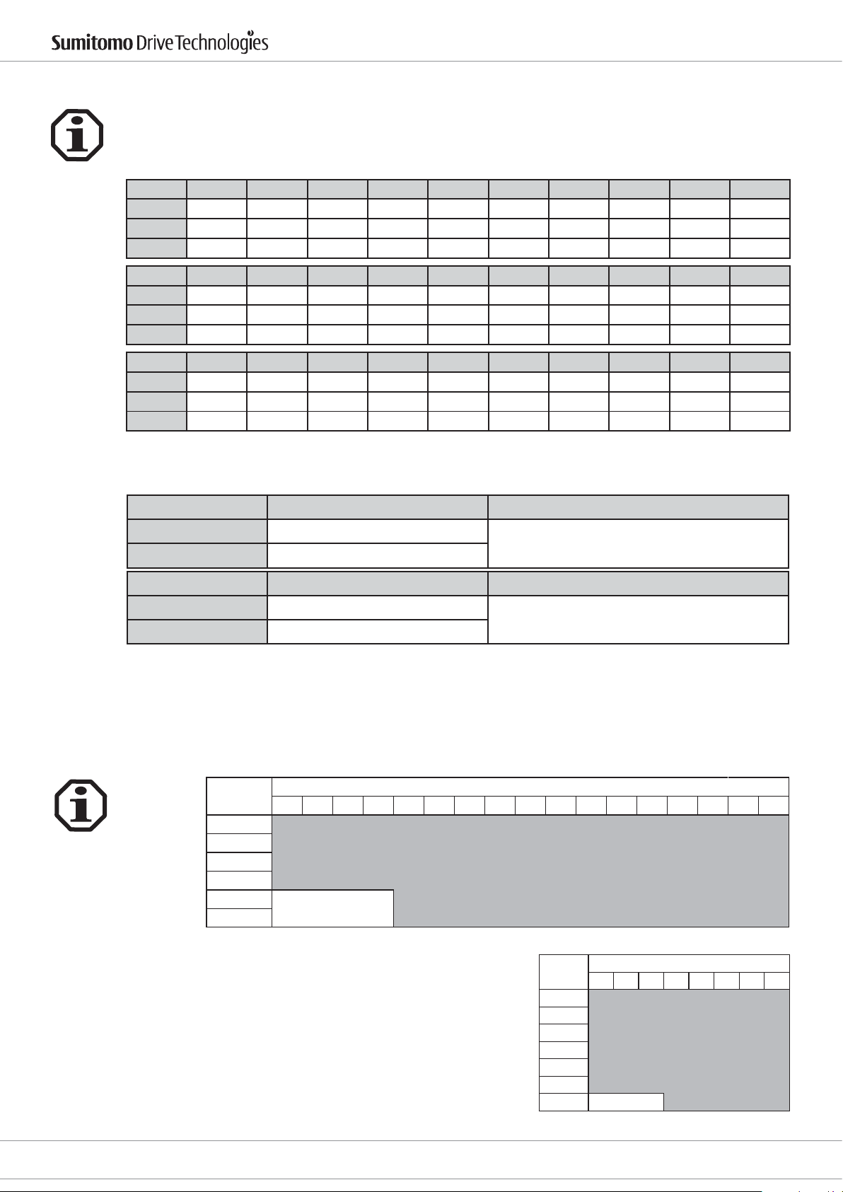
8.1.2 Grease lubrication with top up
CYCLO Drive 6000's that are lled with Esso Unirex N2 must be topped up for the rst time after 500 operating
hours but at least after 2 months. Further top ups in accordance with the table below:
For lubrication quantities (g)when changing when topping up, see paragraph 9.1.
Size 613XDA 613XDB 613XDC 614XDA 614XDB 614XDC 616XDA 616XDB 617XDA 617XDB
1st stage 25 60 120 25 60 120 60 120 60 120
2nd stage 450 450 450 450 450 450 750 750 1000 1000
Output 300 300 300 300 300 300 300 300 500 500
Size 618XDA 618XDB 619XDA 619XDB 6205DA 6205DB 6215DA 6215DB 6225DA 6225DB
1st stage 120 450 330 450 330 450 450 750 450 1000
2nd stage 1100 1100 1500 1500 1500 1500 2000 2000 2500 2500
Output 600 600 700 700 700 700 800 800 900 900
Size 6235DA 6235DB 6245DA 6245DB 6255DA 6255DB 6265DA - - -
1st stage 750 1100 750 1100 1000 1500 1500 - - -
2nd stage 4000 4000 4500 4500 6000 6000 8000 - - -
Output 1000 1000 1100 1100 1200 1200 1300 - - -
X = Means type 0 oder 5
Drive 6000 Operating Manual
Top up times
Operating conditions Time of topping up Notes
up to 10 hours/ day every 3 - 6 months
10 - 24 hours/ day Every 500 - 1,000 hours
Area Time of lubrication change Notes
Drive and transmission every 2 - 3 years
Output every 3 - 5 years
Filling with and changing lubricants:
CYCLO Drive 6000's from size 613 are lubricated in 2 stages and tted with grease nipples for regular topping up.
8.2 Oil lubrication
8.2.1 Type of oil lubrication
8.2.1.1 Horizontal installation position
Size
613X
614X
616X
617X
618X
619X
X = Means type 0 oder 5
356811131517212529354351597187
Under dicult operating conditions the lubrication change
intervals must be reduced.
Under dicult operating conditions the lubrication change
intervals must be reduced.
Single reduction units
Oil bath
30
D6000_DEU_ENG_01_2010_2.0_991179
E-Mail: [email protected]
www.sumitomodriveeurope.com
Size
Single reduction units
11 15 21 29 35 43 59 87
6205
6215
6225
6235
6245
6255
6275
Phone +49 (0) 8136 66 0
Oil bath
Cyclostraße 92
85229 Markt Indersdorf
Page 32
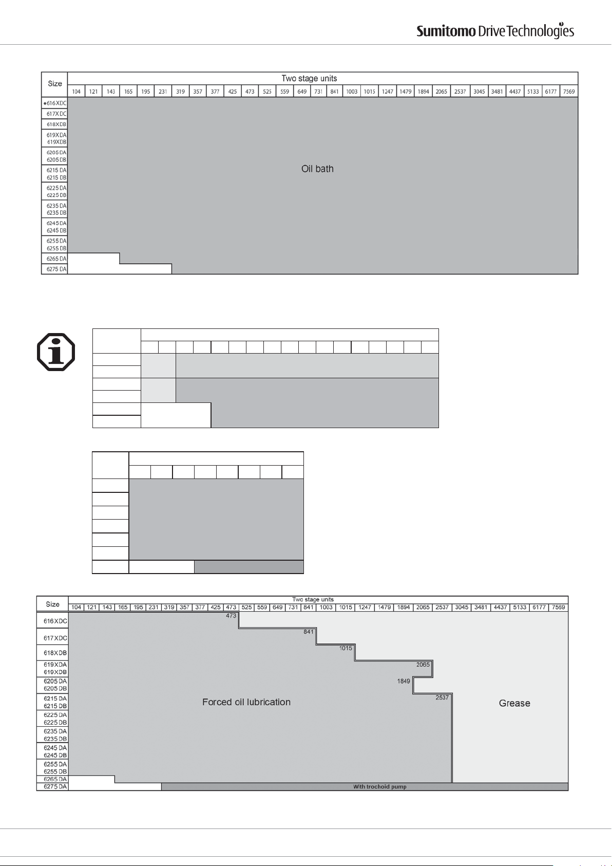
Drive 6000 Operating Manual
X = Means type 0 oder 5
also grease lubrication possible
*
8.2.1.2 Vertical installation position
Size
613X
614X
616X
617X
356811131517212529354351597187
Grease Oil bath
Grease Forced oil lubrication
Single reduction units
618
619X
X = Means type 0 oder 5
Size
11 15 21 29 35 43 59 87
Single reduction units
6205
6215
6225
6235
Forced oil lubrication
6245
6255
6275 With trochoid pump
X = Means type 0 oder 5
Cyclostraße 92
85229 Markt Indersdorf
Phone +49 (0) 8136 66 0
E-Mail: [email protected]
www.sumitomodriveeurope.com
D6000_DEU_ENG_01_2010_2.0_991179
31
Page 33
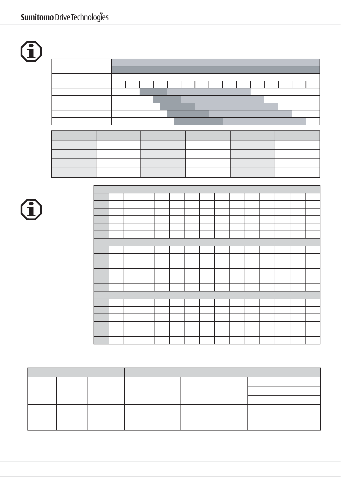
8.2.2 Recommended lubrication oils
All lubrication oils that meet the requirements of DIN 51517 Part 3 are suitable.
Depending on the ambient or operating temperature, the correct viscosity class must be selected in accordance
with DIN 51519.
lubricant as per
DIN 57517 part 3
CLP 68
CLP 100
CLP 150
CLP 220
CLP 320
Manufacturer Brand Manufacturer Brand Manufacturer Brand
ARAL Degol BG DEA Falcon CLP OPTIMOL Ultra
AVIA Gear RSX ELF Reductelf SP SHELL Omala
BP Energol GR-XP KLÜBER Klüberoil GEM 1 TOTAL Carter EP
Castrol Alpha MW MOBIL Mobilgear 600XP ----- ------
Drive 6000 Operating Manual
possible operating temperatures °C
ambient temperature °C
-20°C 0° +20° +40° +60° +80° +100°
8.2.3 Oil quantities
The quantities [l] specied
are average guide values.
The precise quantity must
be checked using the
prescribed oil level in addition to the oil feed quantity
of the external oil pump.
(See please Drive 6000 catalogue lubrication.)
CHH...., CHHX...., CHV...., CHVX....
Size 613X 614X 616X 617X 618X 619X 6205 6215 6225 6235 6245 6255 6265 6275
0,7 0,7 1,4 1,9 2,5 4,0 5,5 8,5 10 15 16 21 29 56
[l]
Size 616XDC 617XDC 618XDA 618XDB 619XDA 619XDB 6205DB 6205DB 6215DA 6215DB 6225DA 6225DB 6235DA 6235DB
1,5 2,4 3,5 3,5 5,8 6,0 6,0 6,0 10 10 11 11 17 17
[l]
Size 6245DA 6245DB 6255DA 6255DB 6265DA 6275DA
18 18 23 23 32 70
[l]
CVV...., CVVX....
Size 613X 614X 616X 617X 618X 619X 6205 6215 6225 6235 6245 6255 6265 6275
1,1 1,1 1,0 1,9 2,0 2,7 5,7 7,5 10 12 15 42 51 60
[l]
Size 616XDC 617XDC 618XDA 618XDB 619XDA 619XDB 6205DB 6205DB 6215DA 6215DB 6225DA 6225DB 6235DA 6235DB
1,0 1,9 2,0 2,0 2,7 2,7 11 11 14 14 18 18 23 23
[l]
Size 6245DA 6245DB 6255DA 6255DB 6265DA 6275DA
29 29 42 42 51 60
[l]
CHF...., CHFX....
Size 613X 614X 616X 617X 618X 619X 6205 6215 6225 6235 6245 6255 6265 6275
0,250,250,91,51,323457,58111430
[l]
Size 616XDC 617XDC 618XDA 618XDB 619XDA 619XDB 6205DB 6205DB 6215DA 6215DB 6225DA 6225DB 6235DA 6235DB
1,0 2,0 2,3 2,3 3,8 4,0 4,0 4,0 5,5 5,5 6,0 6,0 9,5 9,5
[l]
Size 6245DA 6245DB 6255DA 6255DB 6265DA 6275DA
10 10 13 13 17 44
[l]
X = Means type 0 oder 5
Positive Displacement (Trochoid) Pump Type
Cyclo Drive Trochoid Pump
50 Hz Zone
Typ
Frame
Size
Reduction
Ratio
Pump Type Pump Motor
Flow Max Pressure
l/min Bar
Vertical
Shaft
Note: Consult the factory, when using an converter
Positive Displacement (Trochoid) Pump Lubrication:
Forced oil lubrication is accomplished by using a positive displacement pump and motor that requires an additional electric power source. It is
recommended that the main motor be interlocked with the pump motor
to avoid operation without lubrication. The pump must be started 30 seconds or longer before the main motor is operated.
32
D6000_DEU_ENG_01_2010_2.0_991179
6275
6275 DA All TOP 204 HA-VB3 1/2 HP (0,4 kW)4P 6,0 16
29, 43,
59, 87
TOP 216HA-VB3 1 HP (0,75 kW) 4P 24,0 8
E-Mail: [email protected]
www.sumitomodriveeurope.com
Phone +49 (0) 8136 66 0
Cyclostraße 92
85229 Markt Indersdorf
Page 34
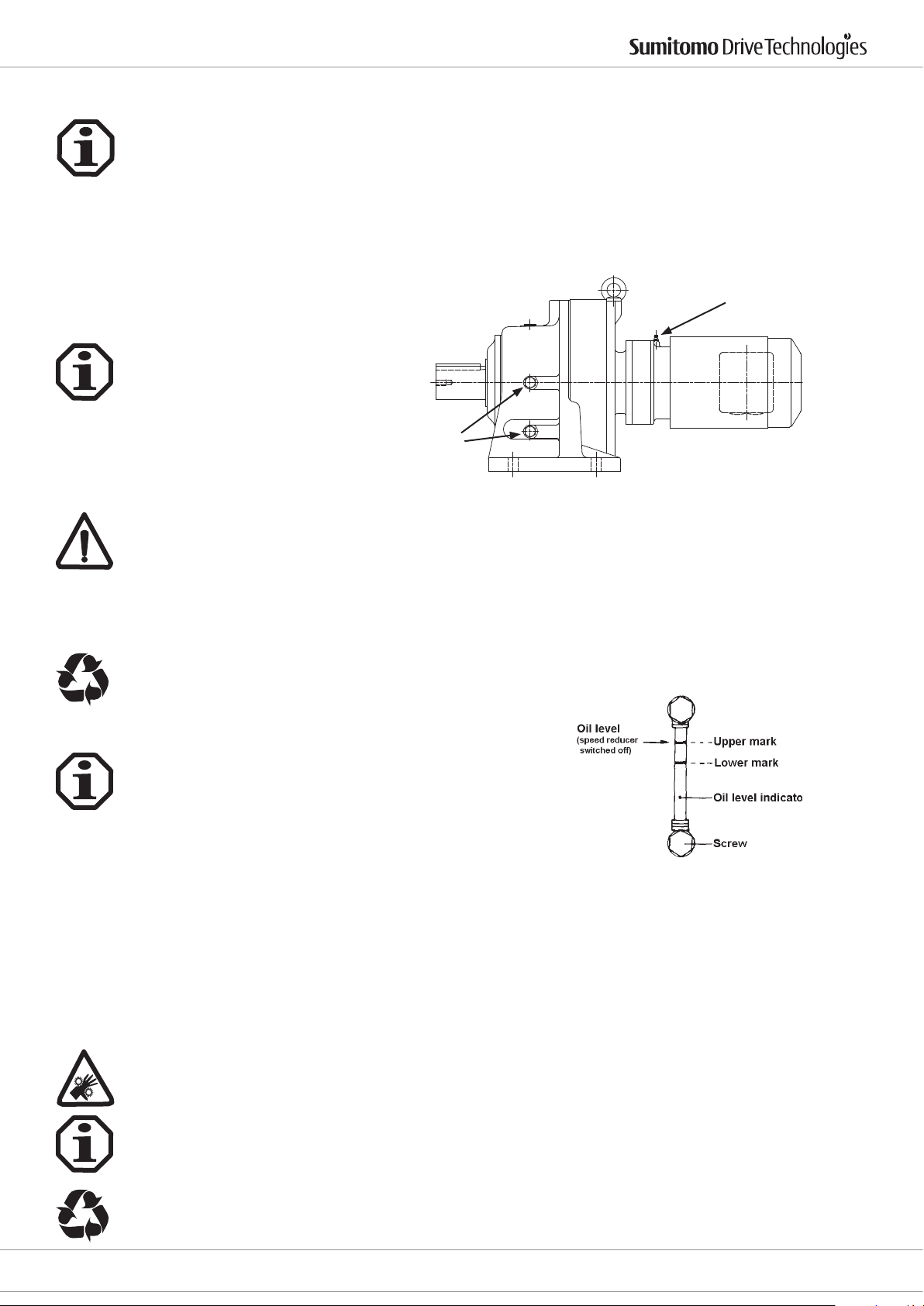
Drive 6000 Operating Manual
8.2.4 Oil change intervals
The correct oil level should be checked every 5000 hours. If the oil is dirty, burnt or viscous, change the oil immediately and, if necessary, ush out the gearbox.
Under normal operating conditions we recommend changing the oil every 10,000 hours. The intervals should not
be more than 2 years. Shorter oil change intervals (every 3,000 - 5,000 hours) increase the operating life.
It is also very advisable to change the oil after the rst 500 hours.
The recommendations above may be changed under other operating conditions such as high temperature, high
humidity or a corrosive environment. If one of these situations applies, the oil must be changed more frequently.
9. Inspection and maintenance work
9.1 Topping up grease lubricated gearboxes
Grease control screws
Unscrew the lubrication control screw on the housing and, using a grease gun, top up the grease via the grease
nipple on the ange on the drive side or on the motor ange.
Top the gearbox up slowly during operation to ensure that the lubricant circulates properly.
At each top up about a third to a half of the quantity of grease in the table in Section 8.1.2 must be topped up for
the rst stage. If too much grease is used the lubricant may heat up to an unacceptable extent when the machine
warms up or grease may get into the motor or may leak because of excess pressure.
Wipe the excess grease o the lubrication control screws and dispose of properly.
9.2 Checking the oil level
The oil level can be checked on the oil level indicator.
Grease nipple
With horizontally installed gearboxes the oil level indicator is normally located on the right hand side of the gearbox, viewed from the drive shaft. As the oil level indicator can be tted both on the left and the right hand side,
the best side for reading it must be selected.
During operation the lower mark on the oil level indicator is considered the guide for the normal oil level. Immediately after start up the oil level may fall below the red mark. However, this is not important as the oil level will
go up again when the oil viscosity goes down as a result of the unit warming up.
9.3 Checking the oil
· Switch the gear motor o and ensure that it cannot be turned on again accidentally.
· Wait until the gearbox has cooled down - Risk of burning.
· Remove some oil from the oil drain plug.
· Check the composition of the oil.
· Check the viscosity.
· If the oil appears to be very dirty on visual inspection, it is advisable to change the oil outside the maintenance
intervals set out in Section 8.2.4 "Oil change intervals".
The oil sample removed must be disposed of properly.
Cyclostraße 92
85229 Markt Indersdorf
Phone +49 (0) 8136 66 0
E-Mail: [email protected]
www.sumitomodriveeurope.com
D6000_DEU_ENG_01_2010_2.0_991179
33
Page 35
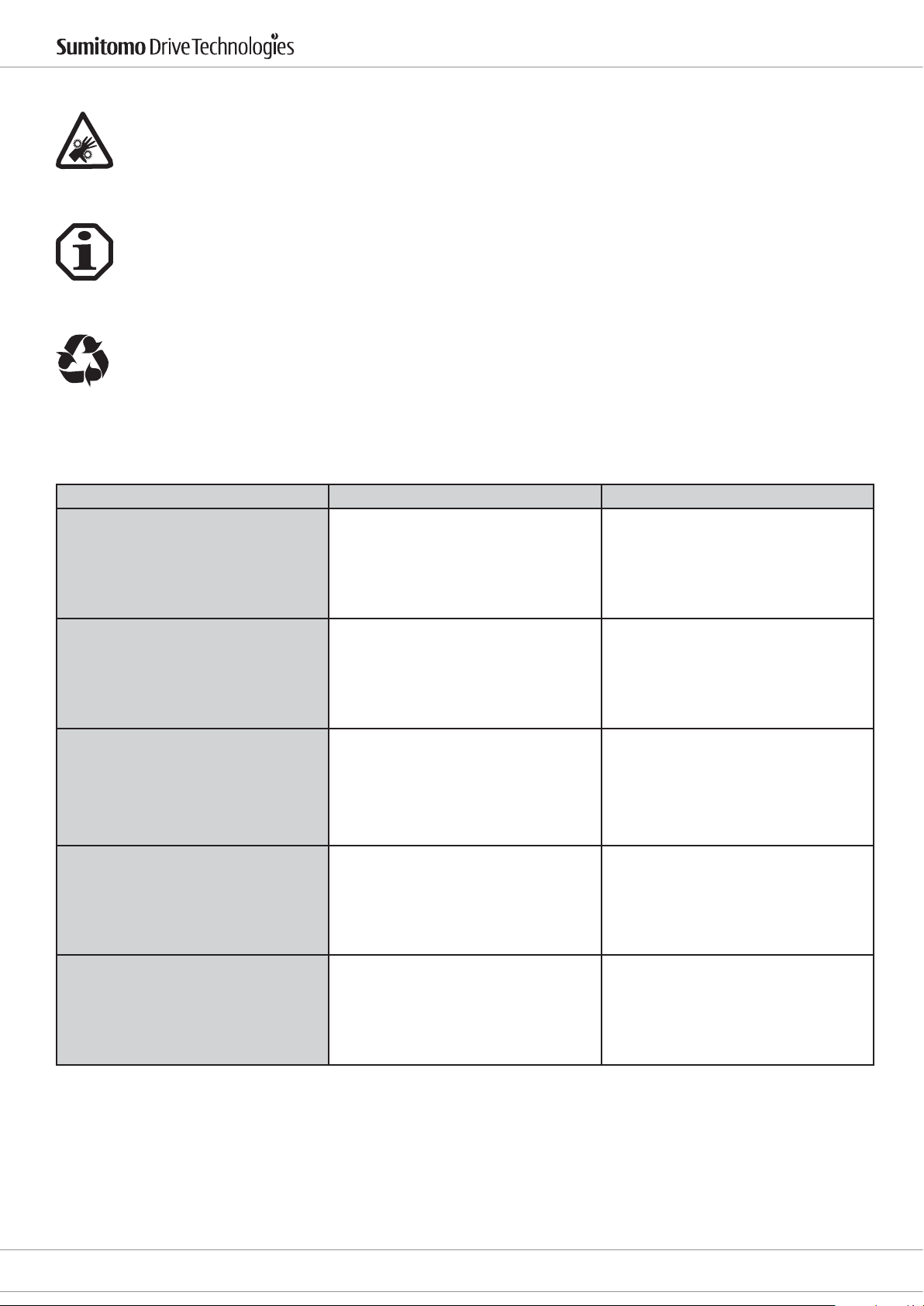
9.4 Changing the oil
· Switch the gear motor o and ensure that it cannot be turned on again accidentally.
· Wait until the gearbox has cooled down - Risk of burning.
· Only change the oil when the gearbox is at operating temperature.
· Put a receptacle under the oil drain plug.
· Remove the oil level indicator, the bleed screw/ valve and the oil drain plug.
· Drain the oil completely.
· Screw the oil drain plug in.
· Fill with new oil through the oil lling plug in accordance with the oil recommendations. Before using other
types of oil please contact SCG.
· Fill the quantity of oil as set out in Section 8.2.3 "Oil quantities".
· Check on the oil level display.
· Replace the bleed screw/ valve.
The drained oil must be disposed of properly.
10. Notes on malfunctions
Possible malfunctions - Troubleshooting and action to be taken
Malfunction Possible cause Troubleshooting
Drive 6000 Operating Manual
1. Unwinding/ grinding noise:
Abnormal, steady running noises
Abnormal, uneven running noises Foreign bodies in the oil
Oil is leaking 1)
- at the gearbox cover
- at the motor ange
- at the motor shaft sealing ring
- at the gearbox ange
- at the output side shaft sealing ring.
Oil leaks from the bleed valve
Damaged bearing
2. Knocking noise: Problem in the transmission
1. Seal on the gearbox cover is leaking
2. Seal faulty
3. Gearbox has not been ventilated.
- too much oil
- Drive installed in the wrong model
- frequent cold start (oil foams up) and/
or oil level high
1. Check oil (see inspection and maintenance work), change bearings
2. Call customer services
Check oil (see inspection and maintenance work)
Stop the drive and call customer services
1. Tighten screws on the gearbox cover
and examine the gearbox. If oil continues to leak: Call customer services
2. Call customer services
3. Bleed the gearbox (see Congurations)
Correct oil level (see Checking oil level).
Fit the bleed valve correctly and correct
the oil level (see Correcting oil level).
Drive shaft doesn't turn although the
motor is running or the drive shaft is
turned
Small quantities of oil or grease escaping from the shaft sealing ring must be considered normal in the running in phase (24
hours running time) (see also DIN 3761).
34
D6000_DEU_ENG_01_2010_2.0_991179
The shaft hub connection in the gearbox is broken
E-Mail: [email protected]
www.sumitomodriveeurope.com
Send the gearbox/ gear motor for repair
Cyclostraße 92
Phone +49 (0) 8136 66 0
85229 Markt Indersdorf
Page 36
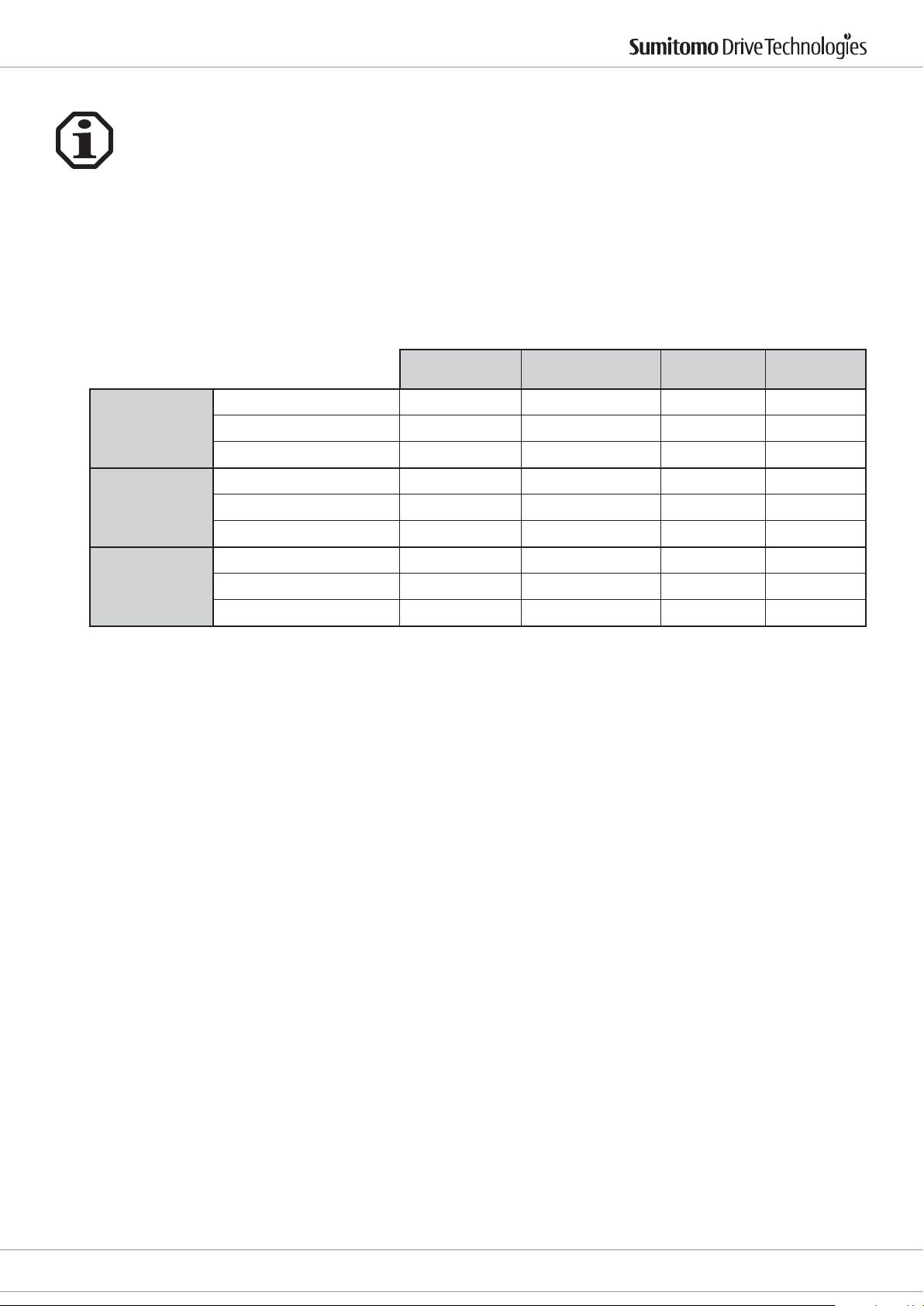
Drive 6000 Operating Manual
11. EC machinery directive
Reducers
Reducers are considered as “machinery components” and are not subject of the EC machinery
directive 2006/42/EG.
The start of operation within the ambit of the EC machinery directive is forbidden, as long as
it is not conrmed, that the machine, where the reducer is built in, complies with this directive.
From 2010 no manufacturers declaration, EC conformity declaration and declaration of incorporation
will be issued.
Gearmotors
For gearmotors a conformity declaration according low voltage directive will be issued.
reducer
gearmotor
inverter
machine directive
2006/42/EG
CE mark no no no yes
declaration of conformity no no no yes
declaration of incorporation no no no no
CE mark no yes (motor) no yes (reducer)
declaration of conformity no yes (motor) no yes (reducer)
declaration of incorporation no no no no
CE mark no yes (inverter) yes no
declaration of conformity no yes (inverter) yse no
declaration of incorporation no no no no
low voltage directive
73/23/EG
EMV 89/336/EG ATEX 94/9/EG
Cyclostraße 92
85229 Markt Indersdorf
Phone +49 (0) 8136 66 0
E-Mail: [email protected]
www.sumitomodriveeurope.com
D6000_DEU_ENG_01_2010_2.0_991179
35
Page 37
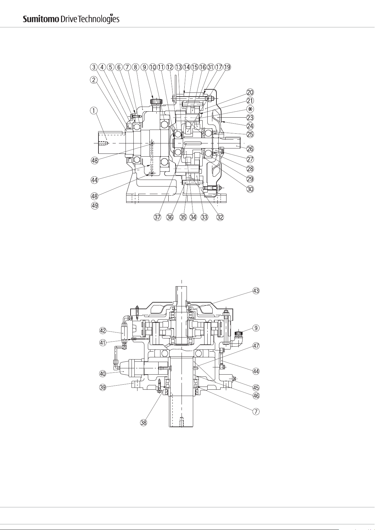
12. Construction drawing - Schnittzeichnung
Drive 6000 Operating Manual
Type CHH (Horizontal, Reducer)
Single Reduction (Example: Frame size 6175)
Typ CHH (Horizontal, Getriebe)
Einstug (Beispiel: Größe 6175)
Type CVV (Vertical, Reducer)
Single Reduction (Example: Frame size 6225)
36
D6000_DEU_ENG_01_2010_2.0_991179
Typ CVV (Vertikal, Getriebe)
Einstug (Beispiel: Größe 6225)
E-Mail: [email protected]
www.sumitomodriveeurope.com
Phone +49 (0) 8136 66 0
Cyclostraße 92
85229 Markt Indersdorf
Page 38
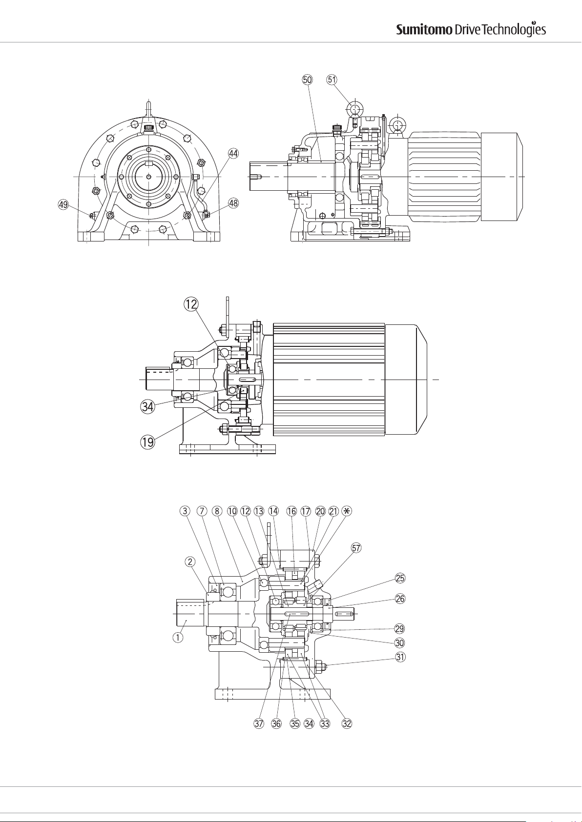
Drive 6000 Operating Manual
Type CHHM (Horizontal, Gearmotor)
Single Reduction (Example: Frame size 6225)
Type CNHM (Horizontal, Gearmotor)
Single Reduction (Example: Frame size 6095)
Type CHHM (Horizontal, Getriebemotor)
Einstug (Beispiel: Größe 6225)
Type CNHM (Horizontal, Getriebemotor)
Einstug (Beispiel: Größe 6095)
Type CNH (Horizontal, Gearmotor)
Single Reduction (Example: Frame size 6105)
Cyclostraße 92
85229 Markt Indersdorf
Phone +49 (0) 8136 66 0
Type CNH (Horizontal, Getriebemotor)
Einstug (Beispiel: Größe 6105)
E-Mail: [email protected]
www.sumitomodriveeurope.com
D6000_DEU_ENG_01_2010_2.0_991179
37
Page 39
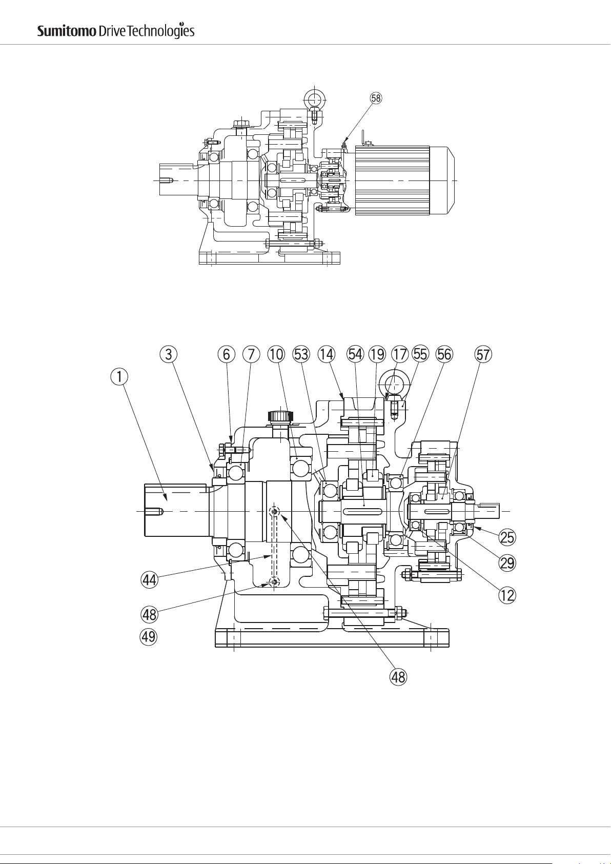
Drive 6000 Operating Manual
Type CHHM (Horizontal, Gearmotor)
Double Reduction (Example: Frame size 6225DB)
Type CHHM (Horizontal, Getriebemotor)
Zweistug (Beispiel: Größe 6225DB)
Type CHH (Horizontal, Gear)
Double Reduction (Example: Frame size 6185DB)
38
D6000_DEU_ENG_01_2010_2.0_991179
Type CHH (Horizontal, Getriebe)
Zweistug (Beispiel: Größe 6185DB)
E-Mail: [email protected]
www.sumitomodriveeurope.com
Phone +49 (0) 8136 66 0
Cyclostraße 92
85229 Markt Indersdorf
Page 40
Drive 6000 Operating Manual
13. Spare parts / Ersatzteile Liste
No. /Nr. Part Name Teilebezeichnung No. /Nr. Part Name Teilebezeichnung
1 Slow speed shaft Abtriebswelle 31 Bolt Schraube
2 Collar Ring für Abtriebswelle 32 Ring gear housing Bolzenring
3 Oil seal Wellendichtring 33 Cycloid discs Kurvenscheiben
4 End cap Dichtungsdeckel 34 Eccentric Exzenter
5 Retaining ring Sicherungsring 35 Ring gear rollers Außenrollen
6 Paper gasket Papierdichtung 36 Ring gear pins Außenbolzen
7 Bearing Lager 37 Key Passfeder
8 Casing Gehäuse 38 End cap Dichtungsdeckel
9 Breather Atmungslter 39 Casing Gehäuse
10 Bearing Lager 40 Oil pump Ölpumpe
11 Retaining ring Sicherungsring 41 Air vent plug Entlüftungsschraube
12 Bearing Lager 42 Oil ow control Strömungswächter
13 Retaining ring Abstimmring 43 Oil retainer Ölstoppring
14 Paper gasket Papierdichtung 44 Oil level gauge Ölstandsschlauch
15 Spacer Stützscheibe 45 Plug Verschlussschraube
16 Spacer ring Zwischenring 46 Spacer Distanzrohr
17 Paper gasket Papierdichtung 47 Cam plate Nockenscheibe
18 Air vent plug Atmungslter 48 Oil gauge plug Öldurchlassschraube
19 Eccentric bearing Exzenterlager 49 Plug Verschlußschraube
20 Flange Flansch 50 Spacer Distanzring
21 Slow speed shaft roller Mitnehmerrollen 51 Eye bolt Ringschraube
* Slow speed shaft pin** Mitnehmerbolzen** 52 Oil ller Ölbehälter
23 Cooling fan Lüfterrad 53 Bearing Lager
24 Fan cover Lüfterhaube 54 Intermediate shaft Stufenwelle
25 Oil seal Wellendichtring 55 Intermediate ange Stufenansch
26 High speed shaft Antriebswelle 56 Bearing Lager
27 Collar Ring für Antriebswelle 57 Eccentric Exzenter
28 Spacer Stützscheibe 58 Grease nipple Schmiernippel
29 Bearing Lager - - 30 Retaining ring Sicherungsring - - -
** Supplied with slow speed shaft assembly only, not as individual items.
** Nur mit Abtriebswelle montiert, nicht separat lieferbar
Cyclostraße 92
85229 Markt Indersdorf
Phone +49 (0) 8136 66 0
E-Mail: [email protected]
www.sumitomodriveeurope.com
D6000_DEU_ENG_01_2010_2.0_991179
39
Page 41

Page 42

Worldwide locations
World Headquarters
JAPAN
Sumitomo Heavy Industries Ltd.
PTC Group
Think Park Tower, 1-1,
Osaki 2-chome,
Shinagawa-ku, Tokyo 141-6025
www.cyclo.shi.co.jp
Headquarters & Manufacturing
EUROPE
Germany
Sumitomo (SHI) Cyclo Drive Germany GmbH
European Headquarters
Cyclostraße 92
85229 Markt Indersdorf
Germany
Tel. +49 (0) 81 36 66-0
Fax +49 (0) 81 36 57 71
E-Mail: [email protected]
www.sumitomodriveeurope.com
Headquarters & Manufacturing
USA
Sumitomo Drive Technologies
Sumitomo Machinery Corp. of America
4200 Holland Boulevard
Chesapeake, VA 23323
Tel. +1 (757) 4 85 33 55
Fax +1 (757) 4 87 31 93
www.smcyclo.com
Subsidiaries & Sales Oces in
Europe
Austria
Sales Oce Austria
Gruentalerstraße 30 A
4020 Linz
Austria
Tel. +43 (0) 7 32 33 09 58
Fax +43 (0) 7 32 33 19 78
Benelux
Sales Oce Benelux
Heikneuterlaan 23
3010 Kessel-Lo/ Leuven
Belgium
Tel. +32 (0) 16 60 83 11
Fax +32 (0) 16 57 16 39
France
SM-Cyclo France S.A.S.
8 Avenue Christian Doppler
77700 Serris
France
Tél. +33 (1) 64 17 17 17
Fax + 33 (1) 64 17 17 18
Italy
SM-Cyclo Italy S.R.L
Via dell ‘Artigianato 23
20010 Cornaredo (MI)
Italy
Tel. +39 (0) 2 93 56 21 21
Fax +39 (0) 2 93 56 98 93
Sumitomo (SHI) Cyclo Drive Germany GmbH
Spain
SM-Cyclo Iberia, S.L.U.
Edicio Gobelas
C/Landabarri Nº 3, 6º B
48940 Leioa-Vizcaya
Spain
Tel. +34 (0) 94 48 05 38 9
Fax +34 (0) 94 48 01 55 0
Sweden
SM-Cyclo Scandinavia AB
Ridbanegatan 4
21377 Malmö
Sweden
Tel. +46 (0) 40 22 00 30
Fax +46 (0) 40 22 00 35
Tur key
SM-Cyclo Turkey
Güç Aktarim Sis. Tic. Ltd.
Büyükdere Çayırbası Cd.
Dede Yusuf Sk. No: 11
34453 Sarıyer Istanbul
Istanbul – Turkey
Tel. +90-212-363 80 50
Fax +90-212-363 85 17
United Kingdom
SM-Cyclo UK, Ltd.
Unit 29, Bergen Way,
Sutton Fields Industrial Estate
Kingston upon Hull
HU7 0YQ, East Yorkshire
United Kingdom
Tel. +44 (0) 14 82 79 03 40
Fax +44 (0) 14 82 79 03 21
D6000_DEU_ENG_01_2010_2.0 991179
 Loading...