

Sumitomo Cyclo BBB5, Cyclo BBB4, Cyclo HBB, Cyclo BBBH, Hyponic Quick Start Manual
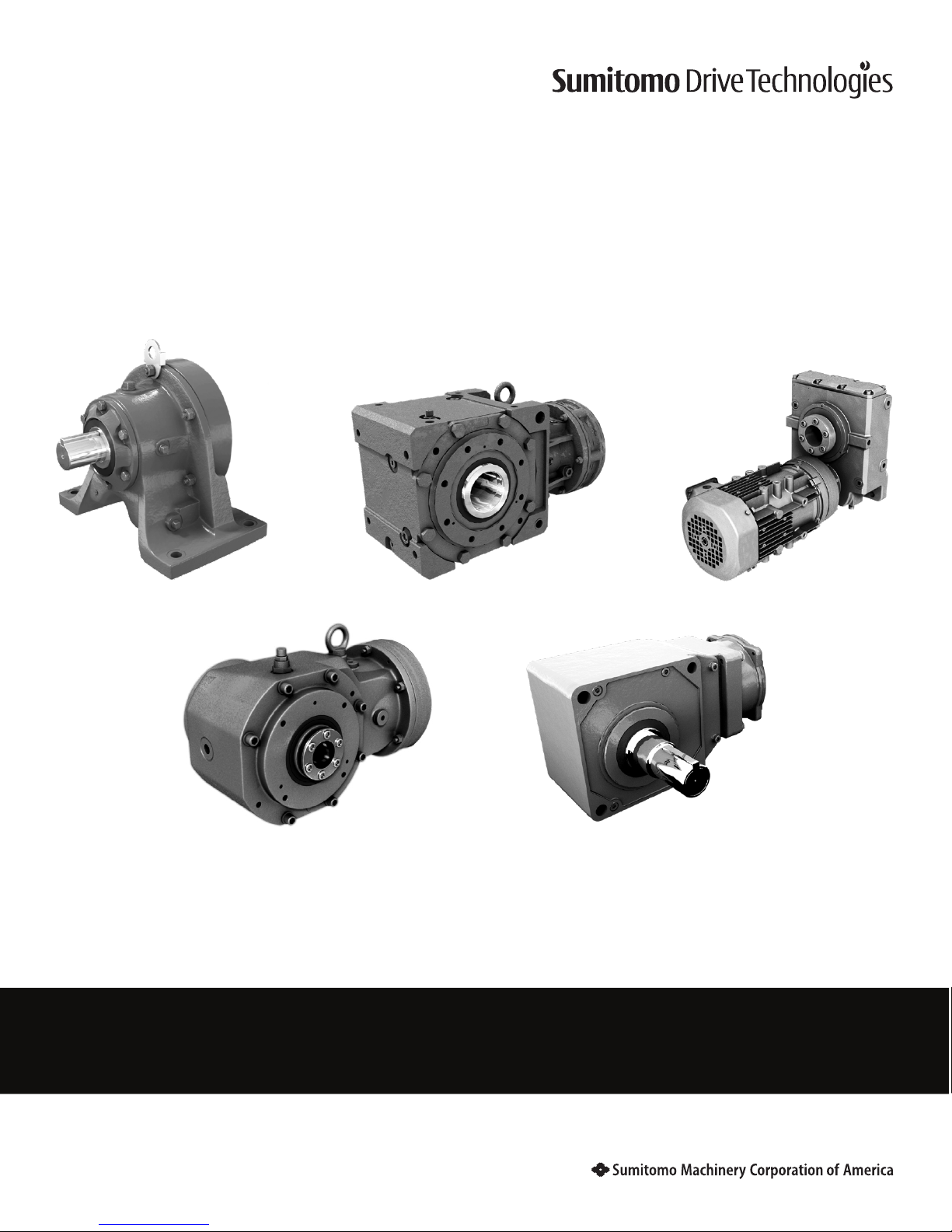
Quick Start Guide
Cyclo®, BBB4, BBB5, BBBH, HBB, Hyponic®
25.001.61.001
Quick Start Guide 2018

Quick Start Guide 1
www.SumitomoDrive.com
Quick Start Guide
Safety Precautions
Review and adhere to the instructions in this manual to:
• ensure trouble-free operation
• protect your rights to make a warranty claim
Read this manual and all accompanying documents thoroughly before use. Understand the machine, information on
safety, and all precautions for correct operation. Sumitomo recommends that this manual is easily accessible for reference at the machine location.
• Only properly trained personnel should transport, install, align, wire, inspect, operate, and maintain
the unit.
• The user should install secondary safety devices for applications involving passenger transportation or
elevators. Failure to do so may result in personnel injury, death, and/or equipment damage.
• Be sure to install and operate speed reducers and gearmotors in compliance with applicable local
and national safety codes. Appropriate guards for rotating shafts are available from factory.
CAUTION:
• Operate the unit only within its design and performance specifications; otherwise, injury or damage to the
system may occur.
• Keep hands and all foreign objects from the internal moving parts of the unit; otherwise, injury or damage
to the system may occur.
• Take damaged units off-line immediately and do not resume operation until properly repaired.
• Modifications or alterations of any kind to the unit will void the warranty and all subsequent claims.
• Consult the factory if speed reducers are driven by DC motors, powered by variable frequency AC drives,
or operated at a speed in excess of standard catalog input speeds.
Inspection Upon Delivery
In order to avoid injury, ensure that the unit is in a stable position before unpacking.
• Verify that the unit received matches your order. Using the incorrect product may cause equipment
damage or personnel injury.
• Do not remove the nameplate from the unit.
Upon delivery, inspect the unit for damage that may have occurred during shipment. Notify the shipping company
immediately if you find any damage. Do not install or operate a damaged unit.
Upon receipt of the reducer/gearmotor, verify that:
• the model number on the unit nameplate matches the purchase order
• the unit was not damaged during shipping
Please consult your Sumitomo agent, distributor, or sales office if you find any defects not attributable to shipping
damage, or if you have any questions.
Contents
Safety Precautions ............................................................................................................................... 1
Inspection of the Nameplate ............................................................................................................ 2
Installation ............................................................................................................................................ 2
Foot Mount - Mounting and Alignment ............................................................................. 4
Keyed Hollow Bore ................................................................................................................... 5
Shrink Disc .................................................................................................................................. 6
Taper-Grip® Bushing ................................................................................................................ 8
Turnbuckle Torque Arm.........................................................................................................13
Tie Rod Torque Arm ................................................................................................................15
T-Type Torque Arm ................................................................................................................. 19
Banjo Type Torque Arm ......................................................................................................... 21
Flange Mount .......................................................................................................................... 23
Motor .................................................................................................................................................... 23
Lubrication ..........................................................................................................................................25
Oil Supply Procedures ...........................................................................................................25
Hyponic® and BBBH ............................................................................................................... 26
Cyclo® 6000, HBB, BBB4 and BBB5 .....................................................................................26
BBB4 and BBB5 in the Y4 Position ......................................................................................30
HBB Oil Fill Quantities ............................................................................................................36
Start-Up ................................................................................................................................................36
Long Term Storage Procedure ........................................................................................................ 37
Gearmotor Quick Start Guide
2 Quick Start Guide
Quick Start Guide 3
www.SumitomoDrive.com
Inspection of the Nameplate
When contacting Sumitomo agent, distributor, or sales office about this product, please be prepared to provide the
following information from the reducer/gearmotor nameplate:
• reducer or gearmotor model number (nomenclature)
• reduction ratio
• serial number
Installation
• Do not use the reducer/gearmotor for specifications other than those shown on the nameplate or in the
manufacturing specification documents. Personnel injury and/or equipment damage may occur.
• Do not place combustible material on or around the unit; fire may occur.
• Do not place any objects around the unit that will prohibit proper ventilation. Inadequate ventilation may
lead to high unit temperature and/or fire.
• Do not step on or hang from the unit. Excessive weight may cause component breakage leading to
personal injury and/or equipment damage.
• Do not touch the shaft, keyway, or motor fan with bare hands; injury may occur.
• For applications in which lubricant leaks could adversely affect operations (i.e., package handling, food
processing), place an oil pan below the unit to protect against contamination that may occur if oil seals
become damaged or worn.
• Do not remove the eye-bolt from the motor, should you need to remove the eye-bolt for any reason,
install a replacement bolt in the tapped hole to prevent water from entering the motor.
Installation Conditions
Standard Ambient Temperature Range: 14° - 104°F (-10° - 40°C)
Ambient Humidity: 85% or less
Altitude: 3,280 feet (1,000 m) or less
Atmosphere: The location should not contain corrosive gas, explosive gas, or
steam. The location should be free of dust and well ventilated.
Location: Indoor – free of dust and water
Consult Sumitomo when the unit will operate in conditions other than those specified above. Special unit
modifications may be required.
Units manufactured according to customer specified application requirements (i.e. outdoor modifications, hightemperature modifications) are designed to operate within the specified environment.
Operation After Storage
Before operating the unit after an extended storage period, ensure that non-metal parts, i.e., oil seals, o-rings, air
breather, have not deteriorated. Non-metal parts may deteriorate easily from exposure to ambient conditions (i.e.,
extreme temperatures, UV rays). Replace deteriorated parts with new before unit start-up.
After starting the unit, verify that there is no abnormal noise, vibration, and/or temperature rise. Immediately stop
the unit and call your local distributor, Original Equipment Manufacturer or Sumitomo directly if you observe any
abnormality.
Installation Angle
Mount the unit in the specified position for which it was ordered. Confirm the mounting position from the gearbox
nameplate.
Consult your local distributor, Original Equipment Manufacturer or Sumitomo directly if the mounting angle is to be
other than horizontal or vertical.
Severe Loading Conditions
For applications with severe vibration and/or frequent starts and stops, Sumitomo recommends the use of highstrength mounting bolts of Grade 10.9 (or greater).
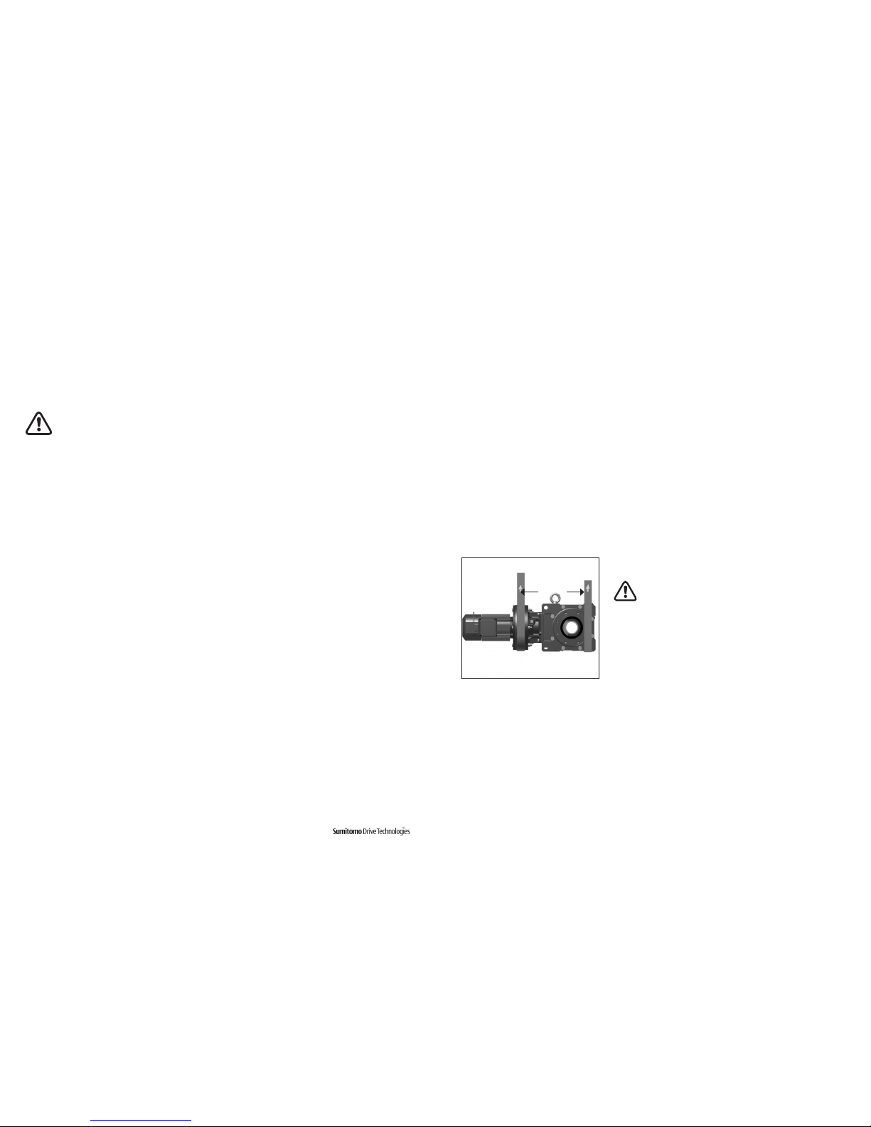
Installation onto the Driven Machine
• Before coupling the reducer/gearmotor to the machine,
verify the appropriate/desired rotation of the machine.
Differences in the rotational direction may cause
personnel injury and/or equipment damage.
• Before operating the unit, ensure that all safety guards
around the rotating components are in-place and secure.
Failure to do so may result in personal injury.
External
Support
4 Quick Start Guide
Quick Start Guide 5
www.SumitomoDrive.com
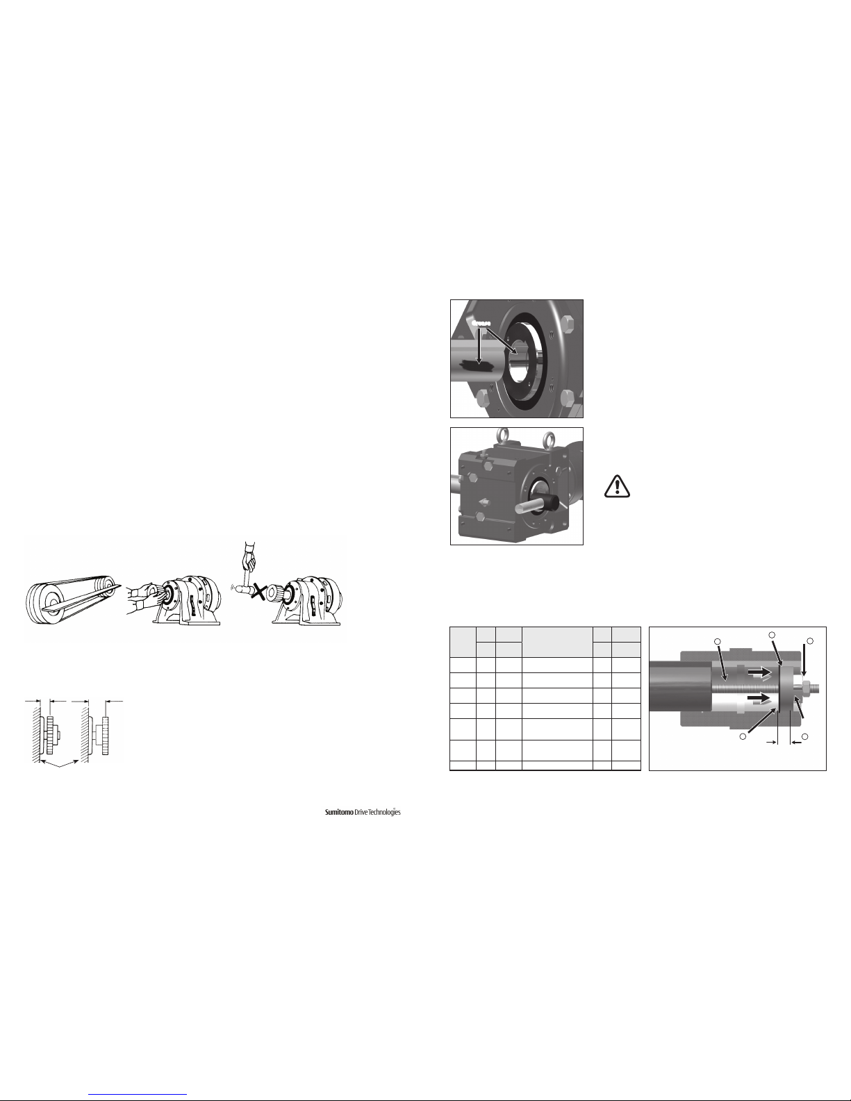
Overhung Load Positions
Overhung loads should be located as close to the reducer housing as possible.
Correct Incorrect
Reducer Housing
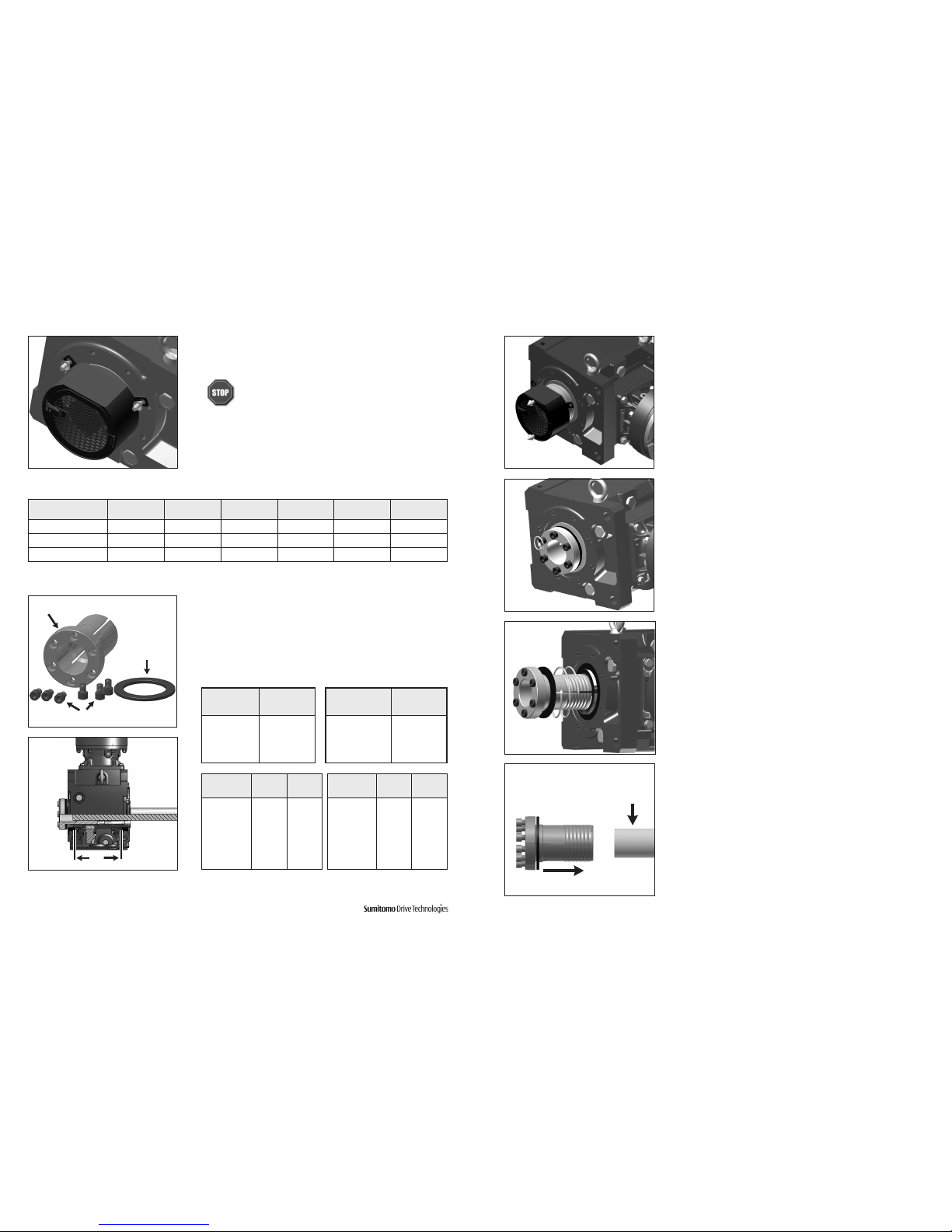
Keyed Hollow Bore
1
Apply molybdenum disulfide grease or similar anti-seize compound,
to the driven shaft surface and inside the reducer keyed hollow bore.
2
Align the driven shaft with the reducer/gearmotor bore and carefully
slide unit onto the driven shaft.
If the fit is tight, strike on the keyed hollow bore with a soft nonmetallic mallet to assist in the assembly.
If using a soft mallet during installation, strike only against
the unit’s steel keyed hollow bore. Do not strike the reducer
housing or oil seal. Damage to the bearings, the housing,
and/or the seals may occur.
Note: If the fit is tight, you may use a jig such as the one shown here
to ease assembly. Sumitomo does not supply a mounting jig. This
information is provided for reference only.
Grease
Size
b c
Size
b c
A2 Bearing A2 Bearing
5Z 25 51104 1120 15 5110
4A/5A 25 51105 1220 13 5110
4B/5B 25 51105 1320 13 5110
4C/5C 25 51105 1420/30/40 15 51201
4D 35 51107
1520/21/22/30/31/40
HZ522/23/24
14 51202
4E 35 51107
1630/31/32/33/34/40
HA635
25 51204
4F 46 51109
Table 1. Jig Dimensions
Spacer b
Retaining Ring a
Ball
Bearing
c
Threaded Rod e
Nut d
A2
Foot Mount - Mounting and Alignment
Mounting
• Consult Sumitomo when the unit will operate in conditions other than those specified above. Special unit
modifications may be required.
• Install the unit so inspection and/or maintenance procedures may be easily performed. Install all units that are not
shaft mounted on a sufficiently rigid base.
Foundations
Foundations must be designed to withstand shock and stress applied from the load side through the reducer.
Secure Housing
When the unit’s operating conditions include excessive vibration and/or frequent starts and stops, secure it on the
mounting surface by inserting dowel pins into the holes provided in the casing feet. This ensures that bending or
shearing forces are reduced on the mounting bolts. Be sure the dowel pins are inserted securely, especially when the
unit will be operated under severe, recurrent peak loads.
Accurate Alignment
When the reducer is connected to the motor and driven machine with couplings, the shafts must be properly aligned.
When the reducer is connected by V-pulleys or sprockets, ensure that the belts or chains are adjusted per manufacturers
recommendations.
6 Quick Start Guide
Quick Start Guide 7
www.SumitomoDrive.com
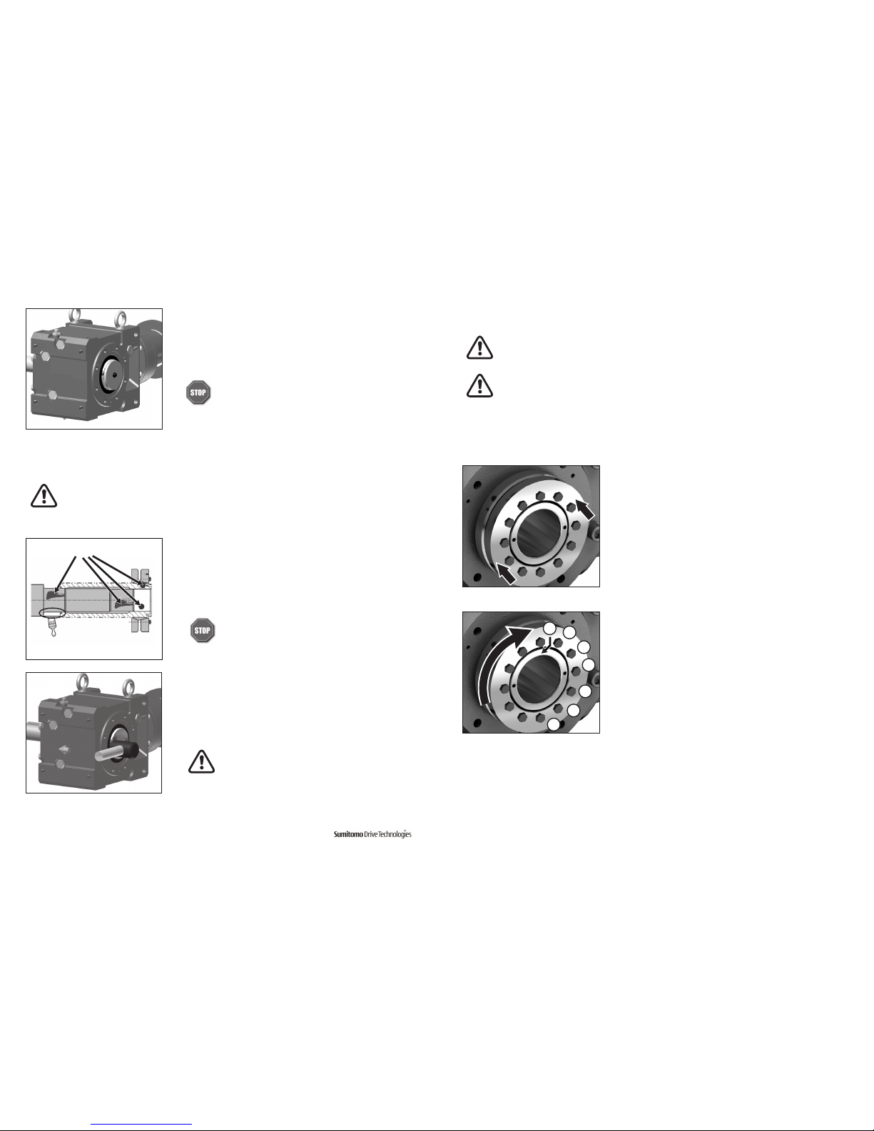
3
Once driven shaft has been completely inserted into the unit’s keyed
hollow bore, secure the shaft in place using a keeper plate as shown
in this example, or some other means of securing the unit to the
driven shaft.
Do not operate unit until the torque arm has been
attached. Refer to the Torque Arm Installation section in
this guide for instructions.
1
Clean and degrease contact surfaces; reducer shaft and bore, and the
machine driven shaft.
Apply Molykote 321 or an equivalent dry film lubricant to the driven
shaft projection opposite from the shrink disc.
Do not apply any friction minimizing compound to the
driven shaft at or near the shrink disc.
2
Align the driven shaft with the bore of reducer/gearmotor bore and
carefully slide unit onto the driven shaft.
If the fit is tight, strike on the reducer hollow bore with a mallet to assist in
the assembly.
If using a soft non-metallic mallet during installation,
strike only against the unit’s steel hollow bore. Do not
strike the reducer housing or oil seal. Damage to the
bearings, the housing, and/or the seals may occur.
Note: If the fit is tight, use a jig such as the one shown in Table 1 to ease assembly. Sumitomo does not supply a
mounting jig. This information is provided for reference only.
Never tighten locking screws before shaft installation. Inner ring may become permanently contracted
even at low tightening torques.
Ensure that all power switches are locked out before installing or removing shrink disc.
Wear safety glasses and protective clothing at all times
Shrink Disc
Before placing unit onto driven shaft, do not apply grease, oil, or anti-seize grease to the entire driven
shaft or to the bore of the shrink disc. Use of these friction-minimizing products will adversely affect the
ability of the unit to transmit torque.
4
Set the (untightened) shrink disc on the reducer shaft.
3
Remove any wooden spacers that may have been used during shipping.
Lightly lubricate the hub outside diameter and shrink disc bore.
5
After confirming the correct position of the hub and shrink
discs, hand tighten three or four equally spaced locking
screws and ensure the discs are parallel. Hand-tighten
remaining locking screws.
6
Using a torque wrench, tighten the screws according to
the initial torque listed in Table 2. Tighten in either a
clockwise or counter-clock wise sequence, using ¼ turns,
until you can no longer complete a ¼ turn for any of the
screws. This procedure keeps the discs parallel.
7
Continue to tighten the screws for two more passes. This
compensates for system induced relaxing of the locking screws.
Degrease
these areas
Apply Molykote 321
to this shaft area only
7
6
5
4
3
2
1
8
Set the torque wrench to the final torque and tighten all locking screws. At this point, no screw should
turn; otherwise, set the torque wrench to the initial torque and repeat steps 6 and 7 above. It is not
necessary to re-torque after equipment has been in operation.
8 Quick Start Guide
Quick Start Guide 9
www.SumitomoDrive.com
Taper-Grip® Bushing
Prior to installation of the gearbox onto the driven shaft, ensure that
the shaft length meets or exceeds the minimum shaft engagement
value “TT” detailed in Table 3.
Shaft Diameter
(in)
Tolerance
(in)
1-3/16 – 1-15/16 +0 / -0.0015
2 – 3-1/8 +0 / -0.0018
3-3/16 – 4-11/16 +0 / -0.0021
4-3/4 – 6-1/2 +0 / -0.0025
Reducer Size
BBB
TT (in) TT (mm)
4A 7.8 198
4B 9.4 237
4C 11 279
4D 12.9 326
4E 14.2 359
4F 16.3 412
Reducer Size
HBB
TT (in) TT (mm)
AA/Z 4.5 113
A 5 126
B 5.7 143
C 7.4 186
D 8.1 204
E 8.9 224
Shaft Diameter
(mm)
Tolerance
(μm)
(30 - 50) (+0 / -39)
(50 - 80) (+0 / -46)
(80 - 120) (+0 / -54)
(120 - 180) (+0 / -63)
Table 3. Driven Shaft Tolerance & Minimum Shaft Engagement
TT
Taper-Grip® Bushing
Socket Head Cap Screws
Thrust Collar
1
Remove bushing cover if unit was supplied with one.
2
Loosen socket head cap screws.
3
Remove (unscrew) Taper-Grip® bushing from the unit.
4
Clean all grease, oil and/or anti-seize grease from the driven shaft.
Failure to do so could result in damage to shaft.
Slide Taper-Grip® bushing onto driven shaft.
Clean Driven
Shaft
9
For units with a safety cover, reinstall the guard over the shrink disc.
Do not operate unit until the torque arm has been
attached. Refer to the Torque Arm Installation section
in this guide for instructions.
Screw Size M5 M6 M8 M10 M12 M16
Initial Torque (Nm) 5.1 12.4 31 63 105 263
Final Torque (Nm) 4.9 12 30 60 100 251
Socket Size (mm) 8 10 13 17 19 24
Table 2. Shrink Disc Size and Tightening Torque
10 Quick Start Guide
Quick Start Guide 11
www.SumitomoDrive.com
5
Inspect and test Taper-Grip® bushing on shaft.
• Check shaft for burrs, corrosion, or warpage. Repair or
replace shaft as necessary.
• Slide bushing back and forth along shaft, checking for
surface irregularities and fit.
• Verify bushing is sized correctly for the shaft diameter.
6
Remove Taper-Grip® bushing from driven shaft.
7
Apply a thin layer of anti-seize grease to the male threads of the
Taper-Grip® bushing only.
Ensure that the anti-seize grease does not enter the TaperGrip® bushing bore.
Do not apply anti-seize grease to the female threads in the
hub.
Apply thin layer of
anti-seize grease to male
threads of bushing only.
Do not apply anti-seize grease
to the female threads in the
hub.
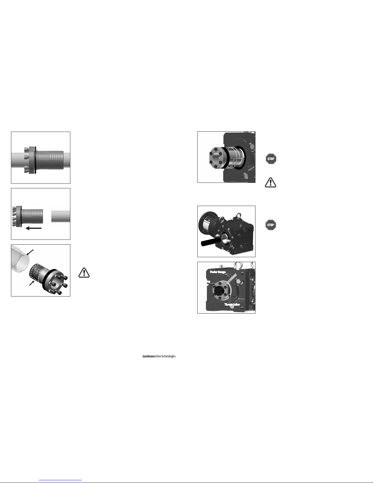
8
Screw Taper-Grip® bushing into the reducer leaving approximately
1 mm gap between the bushing flange and thrust collar.
Do not apply grease, oil, or anti-seize grease to the
driven shaft or the bushing bore before placing the unit
onto driven shaft. Use of these friction-minimizing products
will adversely affect the ability of the unit to transmit
torque.
CAUTION: The reducer must be externally supported prior
to insertion of driven shaft into bushing. External support
MUST be maintained until all bushing socket head cap
screws have been tightened to the appropriate
operational torque.
9
Mount or slide the reducer onto the driven shaft
Do not rock or pry the unit.
10
Screw Bolts into Taper-Grip® bushing.
• Lightly oil threads of each bolt before inserting.
• Finger tighten each bolt to secure in place.
• Be sure to maintain the 1 mm (approximate) gap
between the thrust collar and the bushing flange.
Feeler Gauge
Bushing
Flange
Thrust Collar
 Loading...