

Page 1
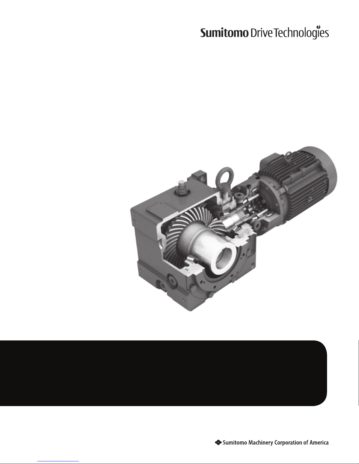
Quick Start Guide
Manual 13.604.61.002 March 2016
Cyclo® BBB4
Bevel Buddybox®
Page 2

Cyclo® BBB4 Quick Start Guide
Quick Start Guide
Cyclo® BBB4
Bevel Buddybox®
Table of Contents
Pages
Shaft and Bushing Installation 4
Taper-Grip Bushing 5
Keyed Hollow Bore 9
Shrink Disc 10
Torque Arm Mounting
Turnbuckle Type 12
Tie-Rod Type 15
T-Type 17
Flange Mount (Banjo) Type 19
Lubrication 22
Page 3

Quick Start Guide Cyclo® BBB4 1
Safety Precautions
Review and adhere to the instructions in this manual to ensure:
• trouble-free Cyclo® BBB4 operation
• your rights to make a warranty claim.
Read this manual and all accompanying documents thoroughly before use. Understand the machine, information on
safety, and all precautions for correct operation. Sumitomo recommends that this manual is easily accessible for reference at the machine location.
• Only properly trained personnel should transport, install, align, wire, inspect, operate, and maintain
the unit.
• The user should install secondary safety devices for applications involving passenger transportation.
Failure to do so may result in personnel injury, death, and/or equipment damage.
• The user should install secondary safety devices for applications involving elevators. Failure to do so may
result in personnel injury, death, and/or equipment damage.
• Be sure to install and operate Cyclo® BBB4 speed reducers and gearmotors in compliance with
applicable local and national safety codes. Appropriate guards for rotating shafts are available from
factory.
CAUTION:
• Operate the unit only within its design and performance specifications; otherwise, injury or damage to the
system may occur.
• Keep hands and all foreign objects from the internal moving parts of the unit; otherwise, injury or damage
to the system may occur.
• Take damaged units off-line immediately and do not resume operation until properly repaired.
• Modifications or alterations of any kind to the unit will void the warranty and all subsequent claims.
• Do not remove the rating plate.
Inspection Upon Delivery
In order to avoid injury, ensure that the unit is in a stable position before unpacking.
• Verify that the unit received matches your order. Using the incorrect product may cause equipment
damage or personnel injury.
• Do not remove the nameplate from the unit.
Upon delivery, inspect the unit for damage that may have occurred during shipment. Notify the shipping company
immediately if you find any damage. Do not install or operate a damaged unit.
Upon receipt of the reducer/gearmotor, verify that:
• the model number on the unit nameplate matches the purchase order
• the unit was not damaged during shipping
• all bolts and nuts are fully tightened.
Please consult your Sumitomo agent, distributor, or sales office if you find any defects or if you have any questions.
Page 4
2 Cyclo® BBB4 Quick Start Guide
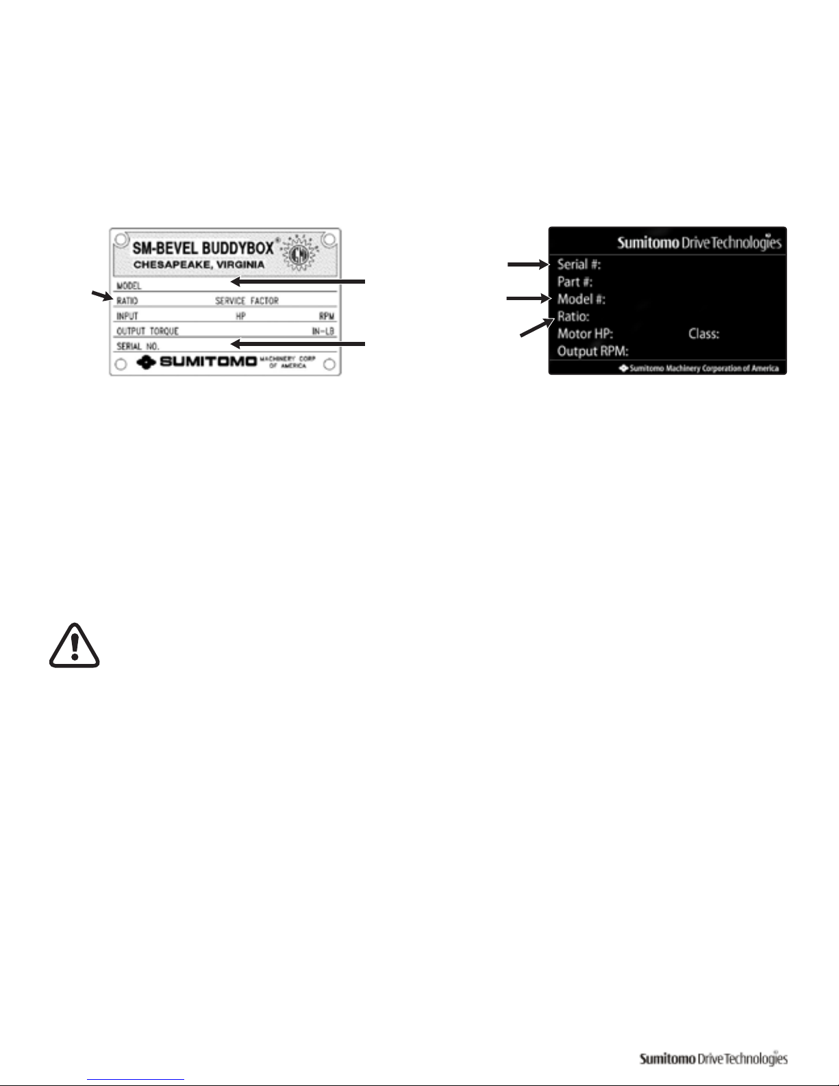
Inspection of the Nameplate
When contacting Sumitomo’ agent, distributor, or sales office about this product, please be prepared to provide the
following information from the reducer/ gearmotor nameplate:
• reducer or gearmotor model number (nomenclature)
• reduction ratio
• serial number
Nominal
Reduction
Ratio
Unit Model
Number
Unit Serial
Number
Non- Metallic Nameplate
Nominal
Reduction
Ratio
Unit Serial
Number
Unit Model
Number
Metal Nameplate
Inspection of Lubrication Method
• Oil lubricated units are shipped without oil, unless the customer specified otherwise when the unit was
ordered. Always fill the unit with the correct type and quantity of lubricant prior to operation.
• Certain models must be filled with lubricant in two separate locations, the bevel gear portion (output) and
the input portion.
Refer to the Lubrication section (page 21) in this manual for detailed lubrication information.
Installation
• Do not use the reducer/gearmotor for specifications other than those shown on the nameplate or in the
manufacturing specification documents. Personnel injury and/or equipment damage may occur.
• Do not place combustible material on or around the unit; fire may occur.
• Do not place any objects around the unit that will prohibit proper ventilation. Inadequate ventilation may
lead to high unit temperature and/or fire.
• Do not step on or hang from the unit. Excessive weight may cause component breakage leading to
personal injury and/or equipment damage.
• Do not touch the shaft, keyway, or motor fan with bare hands; injury may occur.
• For applications in which lubricant leaks could adversely affect operations (i.e., package handling, food
processing), place an oil pan below the unit to protect against contamination that may occur if oil seals
become damaged or worn.
• Do not remove the eye-bolt from the motor, should you need to remove the eye-bolt for any reason,
install a replacement bolt in the tapped hole to prevent water from entering the motor.
Page 5

Quick Start Guide Cyclo® BBB4 3
Installation Location
Ambient Temperature Range: 14° - 104°F (-10° - 40°C)
Ambient Humidity: 85% or less
Altitude: 3,280 feet (1,000 m) or less
Atmosphere: The location should not contain corrosive gas, explosive gas, or
steam. The location should be free of dust and well ventilated.
Location: Indoor – free of dust and water
Consult Sumitomo when the unit will operate in conditions other than those specified above. Special unit
modifications may be required.
Units manufactured according to customer specified application requirements (i.e. outdoor modifications, hightemperature modifications) are designed to operate within the specified environment.
Install the unit so inspection and/or maintenance procedures may be easily performed. Install all units that are not
shaft mounted on a sufficiently rigid base.
Operation After Storage
Before operating the unit after an extended storage period, ensure that non-metal parts, i.e., oil seals, o-rings, air
breather, have not deteriorated. Non-metal parts may deteriorate easily from exposure to ambient conditions (i.e.,
extreme temperatures, UV rays). Replace deteriorated parts with new before unit start-up.
After starting the unit, verify that there is no abnormal noise, vibration, and/or temperature rise. Immediately stop
the unit and call your local distributor, Original Equipment Manufacturer or Sumitomo directly if you observe any
abnormality.
Installation Angle
Mount the unit in the specified position for which it was ordered. Confirm the mounting position from the gearbox
nameplate.
Consult your local distributor, Original Equipment Manufacturer or Sumitomo directly if the mounting angle is to be
other than horizontal or vertical.
Severe Loading Conditions
For applications with severe vibration and/or frequent starts and stops, Sumitomo recommends the use of highstrength mounting bolts of Grade 10.9 (or greater).
Page 6
4 Cyclo® BBB4 Quick Start Guide
Taper-Grip® Installation onto
Driven Shaft
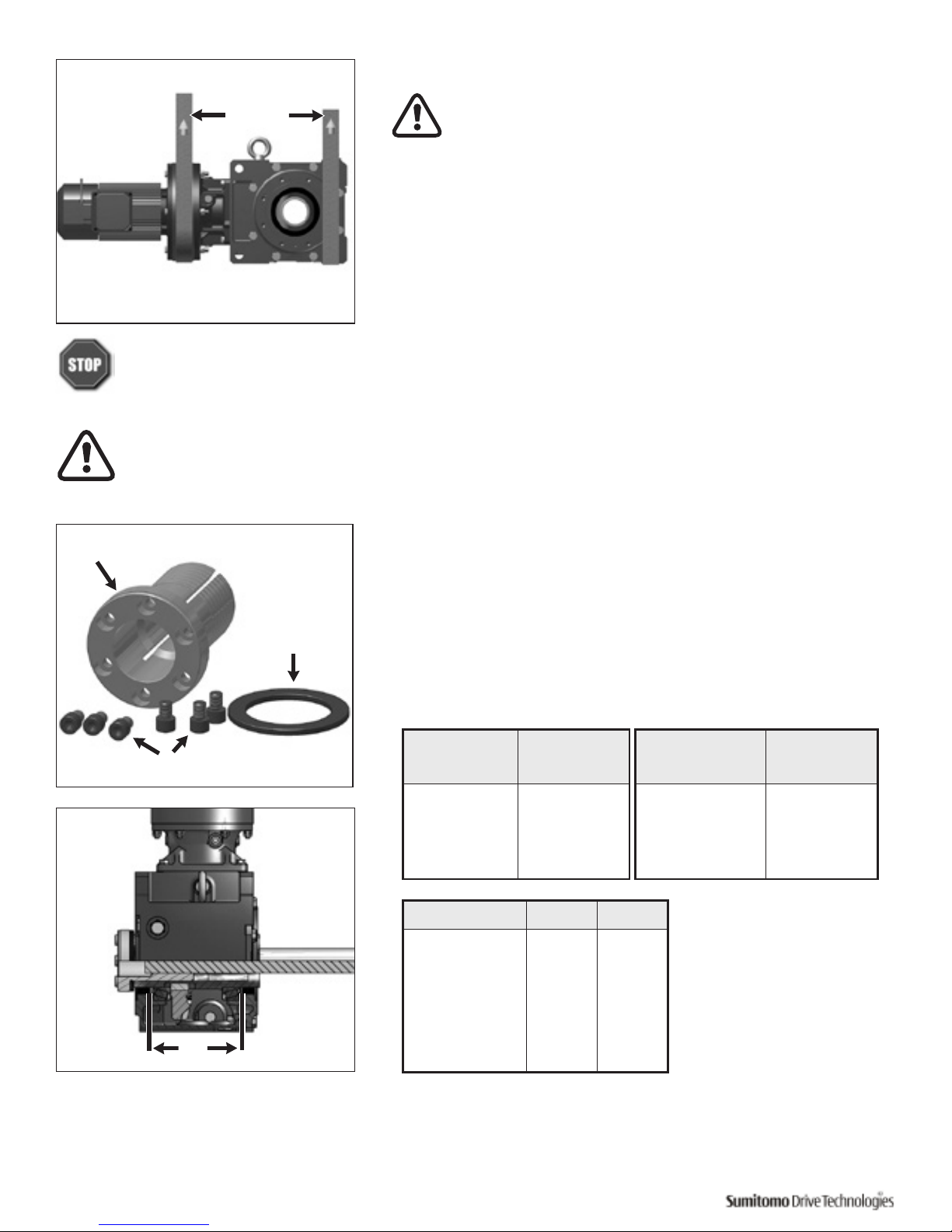
Prior to installation of the Cyclo® BBB4 onto the driven shaft,
ensure that the shaft length meets or exceeds the minimum shaft
engagement value “TT” detailed in Table 1.
Shaft Diameter
(in)
Tolerance
(in)
1-3/16 – 1-15/16 +0 / -0.0015
2 – 3-1/8 +0 / -0.0018
3-3/16 – 4-11/16 +0 / -0.0021
4-3/4 – 6-1/2 +0 / -0.0025
Cyclo® BBB4 Size TT (in) TT (mm)
4A 8.19 (208)
4B 9.53 (242)
4C 10.98 (279)
4D 12.83 (326)
4E 14.13 (359)
4F 16.22 (412)
Shaft Diameter
(mm)
Tolerance
(μm)
(30 - 50) (+0 / -39)
(50 - 80) (+0 / -46)
(80 - 120) (+0 / -54)
(120 - 180) (+0 / -63)
Table 1. Driven Shaft Tolerance and Minimum Shaft
Engagement (TT)
TT
Taper-Grip® Bushing
Socket Head Cap Screws
Thrust Collar
Installation onto the Driven Machine
• Before coupling the reducer/gearmotor to the machine,
verify the appropriate/desired rotation of the machine.
Differences in the rotational direction may cause
personnel injury and/or equipment damage.
• Before operating the unit, ensure that all safety guards
around the rotating components are in-place and secure.
Failure to do so may result in personal injury.
Do not operate shaft mounted units until the torque arm has been attached to the unit and fixed to a
rigid structure. The Torque Arm prevents counter-rotation during unit operation. Refer to Torque Arm
Installation section of this manual (page12).
CAUTION: The Cyclo® BBB4 must be externally supported prior to insertion of driven shaft into bushing.
External support MUST be maintained until unit is secured and mounting bolts have been tightened to the
appropriate torque.
External
Support
Page 7
Quick Start Guide Cyclo® BBB4 5
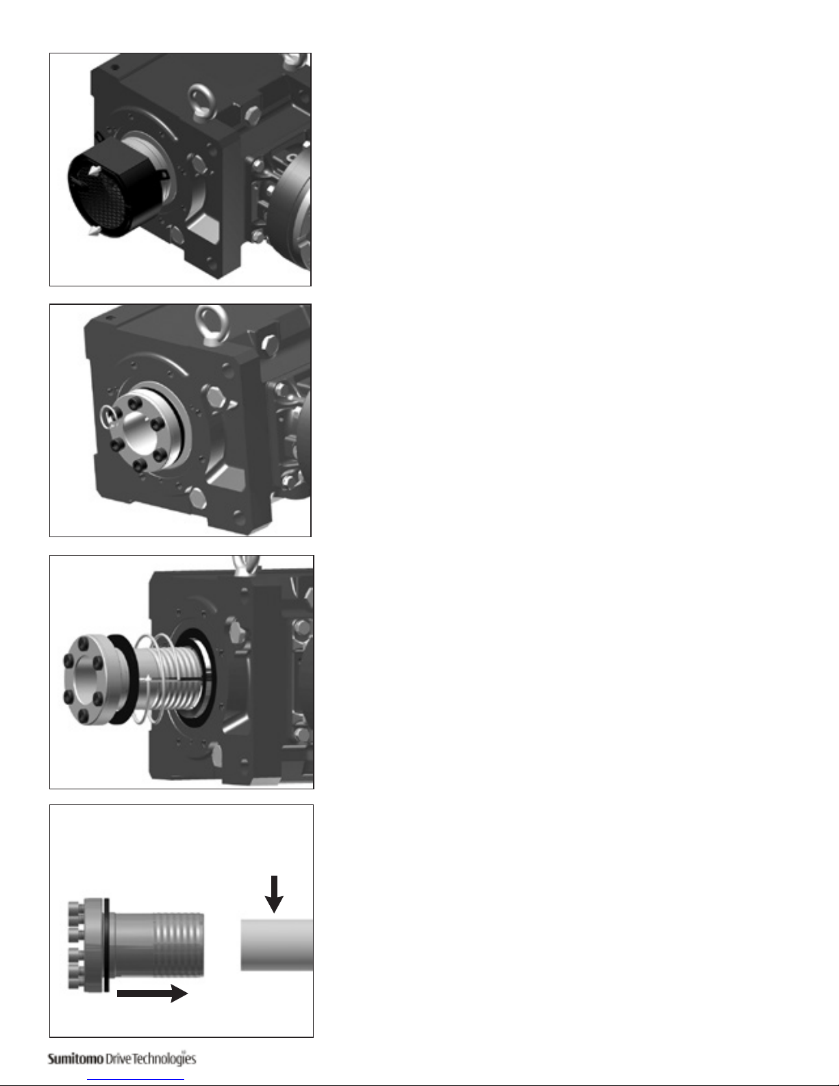
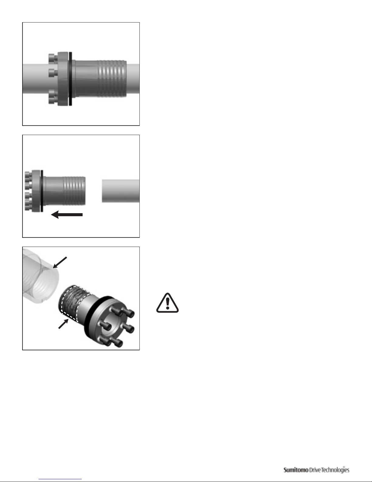
1
Remove bushing cover if unit was supplied with one.
2
Loosen socket head cap screws.
3
Remove (unscrew) Taper-Grip® bushing from the unit.
4
Clean all grease, oil and/or anti-seize grease from the driven shaft.
Failure to do so could result in damage to shaft.
Slide Taper-Grip® bushing onto driven shaft.
Clean Driven
Shaft
Page 8
6 Cyclo® BBB4 Quick Start Guide
5
Inspect and test Taper-Grip® bushing on shaft.
• Check shaft for burrs, corrosion, or warpage. Repair or
replace shaft as necessary.
• Slide bushing back and forth along shaft, checking for
surface irregularities and fit.
• Verify bushing is sized correctly for the shaft diameter.
6
Remove Taper-Grip® bushing from driven shaft.
7
Apply a thin layer of anti-seize grease to the male threads of the
Taper-Grip® bushing only.
Ensure that the anti-seize grease does not enter the Taper-
Grip® bushing bore.
Do not apply anti-seize grease to the female threads in the
hub.
Apply thin layer of
anti-seize grease to male
threads of bushing only.
Do not apply anti-seize grease
to the female threads in the
hub.
Page 9

Quick Start Guide Cyclo® BBB4 7
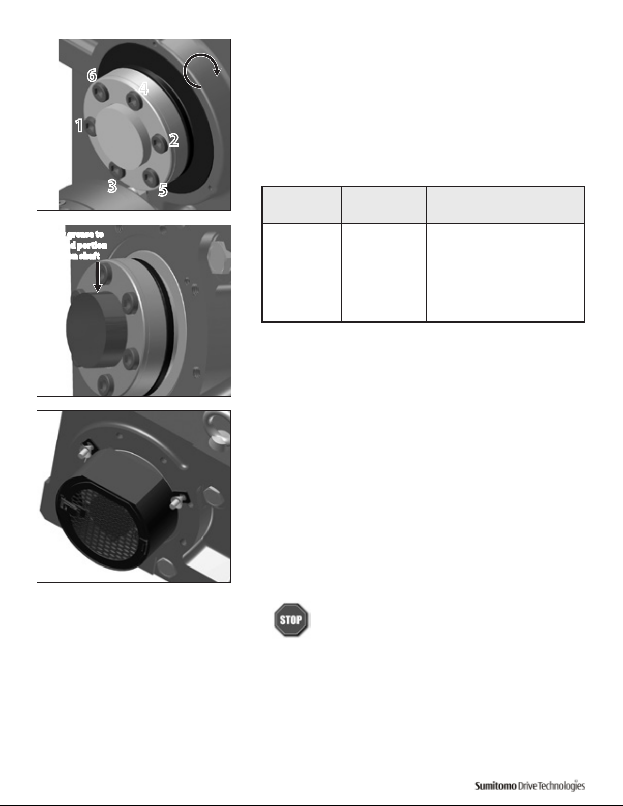
8
Screw Taper-Grip® bushing into Cyclo® BBB4 leaving approximately
1 mm gap between the bushing flange and thrust collar.
Do not apply grease, oil, or anti-seize grease to the
driven shaft or the bushing bore before placing the unit
onto driven shaft. Use of these friction-minimizing products
will adversely affect the ability of the unit to transmit
torque.
CAUTION: The Cyclo® BBB4 must be externally supported
prior to insertion of driven shaft into bushing. External
support MUST be maintained until all bushing socket
head cap screws have been tightened to the appropriate
operational torque.
9
Mount or slide the Cyclo® BBB4 onto the driven shaft
Do not rock or pry the unit.
10
Screw Bolts into Taper-Grip® bushing.
• Lightly oil threads of each bolt before inserting.
• Finger tighten each bolt to secure in place.
• Be sure to maintain the 1 mm (approximate) gap
between the thrust collar and the bushing flange.
Feeler Gauge
Bushing
Flange
Thrust Collar
Page 10
8 Cyclo® BBB4 Quick Start Guide
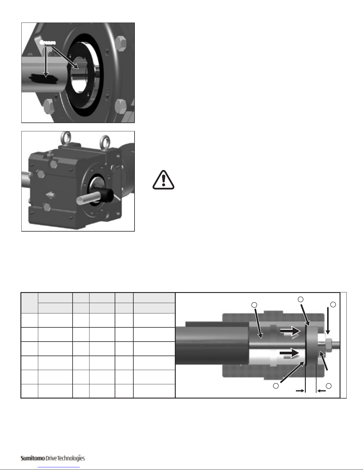
11
Tighten bushing bolts to the correct torque value.
• Following a star pattern, use a torque wrench to
gradually tighten each socket head cap screw in 20%
increments.
• Refer to Table 2, Taper-Grip® Bushing Bolt Tightening
Torques, for the correct operational screw torques.
12
In order to prevent corrosion, apply grease to the exposed portion of the
driven shaft.
• After installing and tightening the bushing bolts with
a torque wrench, apply grease or an anti-corrosion
product to the exposed portion of the shaft.
13
After the reducer has been running for 20 to 30 hours, re-torque the
screws to the values in Table 2. Screw torques should be subsequently
checked at normal service intervals (i.e. every 6 months).
14
For units that include a bushing safety cover, reinstall the guard over
the Taper-Grip® bushing.
Do not operate unit until the torque arm has been attached
to the unit and fixed to a rigid structure. The torque arm
prevents counter-rotation during unit operation. Refer
to torque arm Installation section in this manual for
instructions.
1
2
3
4
5
6
Table 2. Taper-Grip® Bushing Bolt Tightening Torques
Cyclo® BBB4
Size
Screw Qty x Size
Screw Torque
ft-lb (Nm)
4A 6 x M12 56 (75)
4B 6 x M12 104 (140)
4C 6 x M16 185 (250)
4D 6 x M16 223 (300)
4E 8 x M16 223 (300)
4F 10 x M16 223 (300)
Apply grease to
exposed portion
of driven shaft
Page 11
Quick Start Guide Cyclo® BBB4 9
Keyed Hollow Bore Installation onto
Driven Shaft
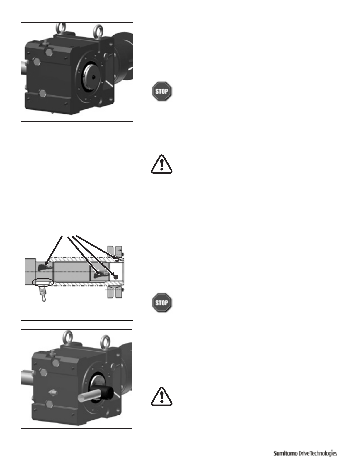
1
Apply molybdenum disulfide grease or similar anti-seize compound,
to the driven shaft surface and inside the reducer keyed hollow bore.
2
Align the driven shaft with the reducer/gearmotor bore and carefully
slide unit onto the driven shaft.
If the fit is tight, strike on the keyed hollow bore with a soft
mallet to assist in the assembly.
If using a soft mallet during installation, strike only against
the unit’s steel keyed hollow bore. Do not strike the reducer
housing or oil seal, damage to the bearings, the housing,
and/or the seals may occur.
Note: If the fit is tight, you may use a jig such as the one shown here
to ease assembly. Sumitomo does not supply a mounting jig. This
information is provided for reference only.
Grease
Size
a b c d e
CC (ISO/JIS) A2 Bearing Nut Threaded Rod
4A 3 25 51104 M16 M16 x 250
4B 65 25 51105 M20 M20 x 300
4C 75 25 51105 M20 M20 x 300
4D 85 35 51107 M24 M24 x 400
4E 100 35 51107 M24 M24 x 400
4F 120 46 51109 M30 M30 x 450
Table 3. Jig Dimensions
Spacer b
Retaining Ring a
Ball
Bearing
c
Threaded Rod e
Nut d
A2
Unit: mm
Page 12
10 Cyclo® BBB4 Quick Start Guide
3
Once driven shaft has been completely inserted into the unit’s keyed
hollow bore, secure the shaft in place using a keeper plate as shown
in this example, or some other means of securing the unit to the
driven shaft.
Do not operate unit until the torque arm has been
attached. Refer to the Torque Arm Installation (page12)
section in this manual for instructions.
Shrink Disc Type Hollow Bore Installation
onto Shaft
Before placing unit onto driven shaft, do not apply grease,
oil, or anti-seize grease to the entire driven shaft or to the
bore of the shrink disc. Use of these friction-minimizing
products will adversely affect the ability of the unit to
transmit torque.
Never tighten locking screws before shaft installation. Inner ring may
become permanently contracted even at low tightening torques.
1
Clean and degrease contact surfaces; reducer shaft and bore, and the
machine driven shaft.
Apply Molykote 321 or an equivalent dry film lubricant to the driven
shaft projection opposite from the shrink disc.
Do Not apply any friction minimizing compound to the
driven shaft at or near the shrink disc.
2
Align the driven shaft with the bore of reducer/gearmotor bore and
carefully slide unit onto the driven shaft.
If the fit is tight, strike on the reducer hollow bore with a mallet to assist in
the assembly.
If using a mallet during installation, strike only against the
unit’s steel hollow bore. Do not strike the reducer housing
or oil seal, damage to the bearings, the housing, and/or the
seals may occur.
Note: If the fit is tight, use a jig such as the one shown in Table 3 to
ease assembly. Sumitomo does not supply a mounting jig. This
information is provided for reference only.
Degrease
these areas
Apply Molykote 321
to this shaft area only
Page 13
Quick Start Guide Cyclo® BBB4 11
3
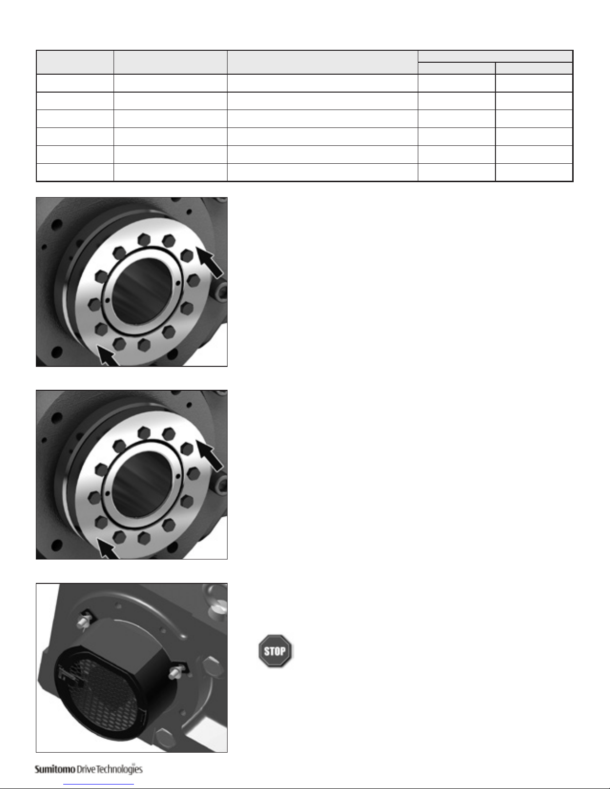
Set the (untightened) shrink disc on the reducer shaft.
4
Tighten bolts to the correct torque value.
• For 3-piece design shrink disc, make sure that both plates
are parallel when tightening bolts.
• After confirming that the shrink disc is set correctly,
tighten the bolts uniformly, in a clockwise pattern while
keeping both plates parallel (not diagonally or ‘star’
pattern).
• It is recommended to tighten respective bolts by 30
degrees each time – until the specified torque is reached.
5
For units with a safety cover, reinstall the guard over the shrink disc.
Do not operate unit until the torque arm has been
attached. Refer to the Torque Arm Installation section in
this manual for instructions.
Size Model (Typical) Bolt
Bolt Torque
ft-lb (Nm)
4A TAS-3071-55 x 68 10 x M6x25 ISO/JIS grade 10.9 9 (12)
4B TAS-3071-65 x 80 7 x M8x30 ISO/JIS grade 12.9 26 (34)
4C TAS-3071-75 x 100 12 x M8x35 ISO/JIS grade 12.9 26 (34)
4D TAS-3071-85 x 110 9 x M10x40 ISO/JIS grade 12.9 51 (68)
4E TAS-3071-100 x 140 10 x M12x45 ISO/JIS grade 12.9 87 (118)
4F TAS-3071-120 x 165 8 x M16x55 ISO/JIS grade 12.9 214 (290)
Table 4. Shrink Disc Size and Tightening Toque
Page 14
12 Cyclo® BBB4 Quick Start Guide
Turnbuckle Torque Arm Installation
Procedure
1
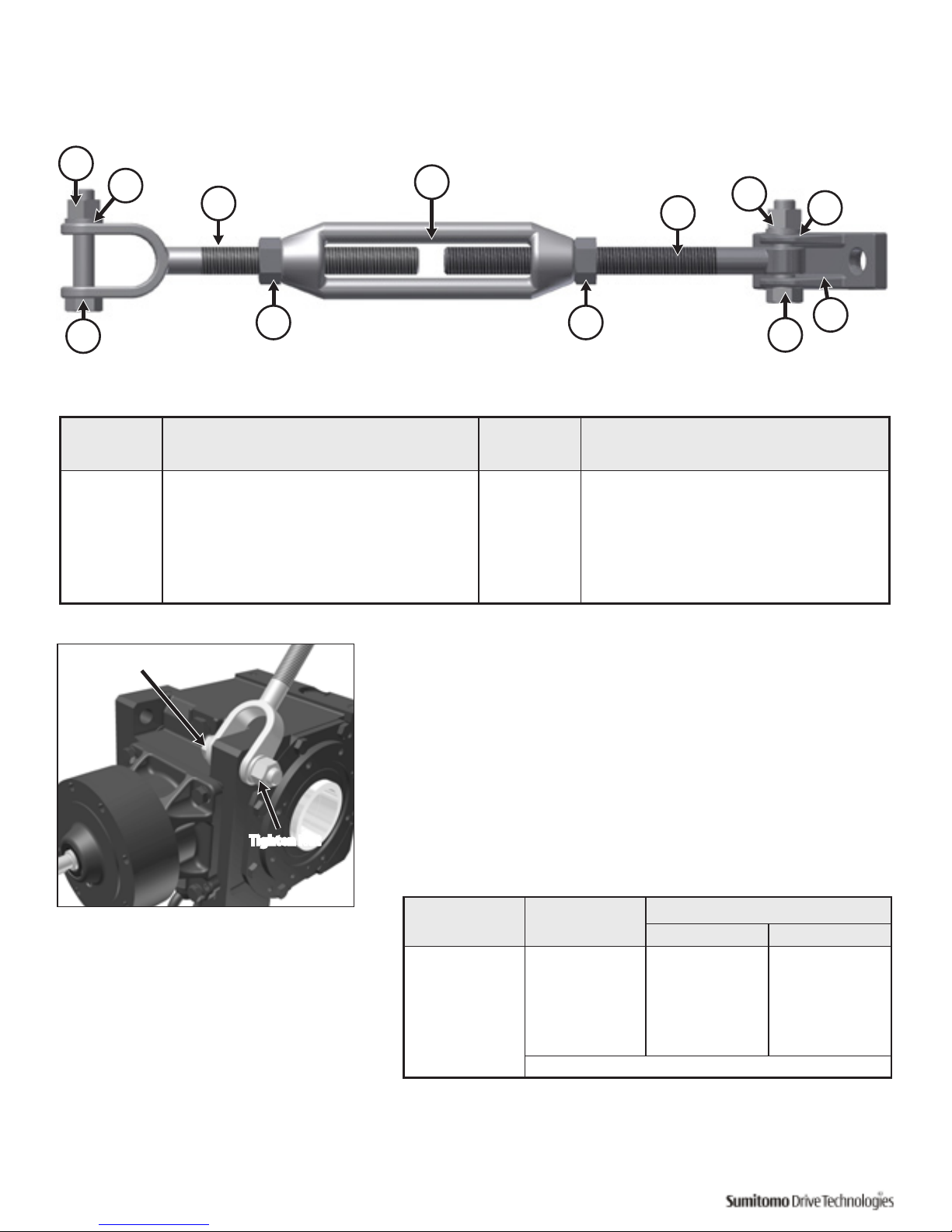
Attach the torque arm threaded extension rod to the bevel housing,
at the housing corner eyelet, using the appropriate nut, bolt and
lockwasher.
Insert the bolt through the brackets, torque arm sleeve (if supplied)
and reducer housing eyelet.
Place the lockwasher on the bolt and secure with nut.
Item Description Item Description
1 Hex Nut 7 Lock Washer
2 Lock Washer 8 Fulcrum Mounting Bracket
3 Threaded Extension Rod 9 Hex Bolt
4 Turnbuckle 10 Locking Nut (if supplied)
5 Threaded Arm 11 Locking Nut (if supplied)
6 Hex Nut 12 Hex Bolt
BBB4 Size Bolt Size
[1]
Torque
ft-lb (Nm)
4A M16 x 75 152 - 167 (206 – 227)
4B M20 x 100 290 – 319 (392 – 431)
4C M24 x 105 507 - 558 (686 – 755)
4D M24 x 125 507 - 558 (686 – 755)
4E
M24 x 125 507 - 558 (686 – 755)
4F
Consult Factory
Note: [1] Bolt ISO/JIS Class 8.8
1
3
4
2
5
6
7
8
9
1011
12
Table 6. Bolt Tightening Torque
Table 5. Turnbuckle Type Torque Arm Parts
Insert Bolt
Tighten Nut
Figure 1. Turnbuckle Type Torque Arm
Page 15
Quick Start Guide Cyclo® BBB4 13
2
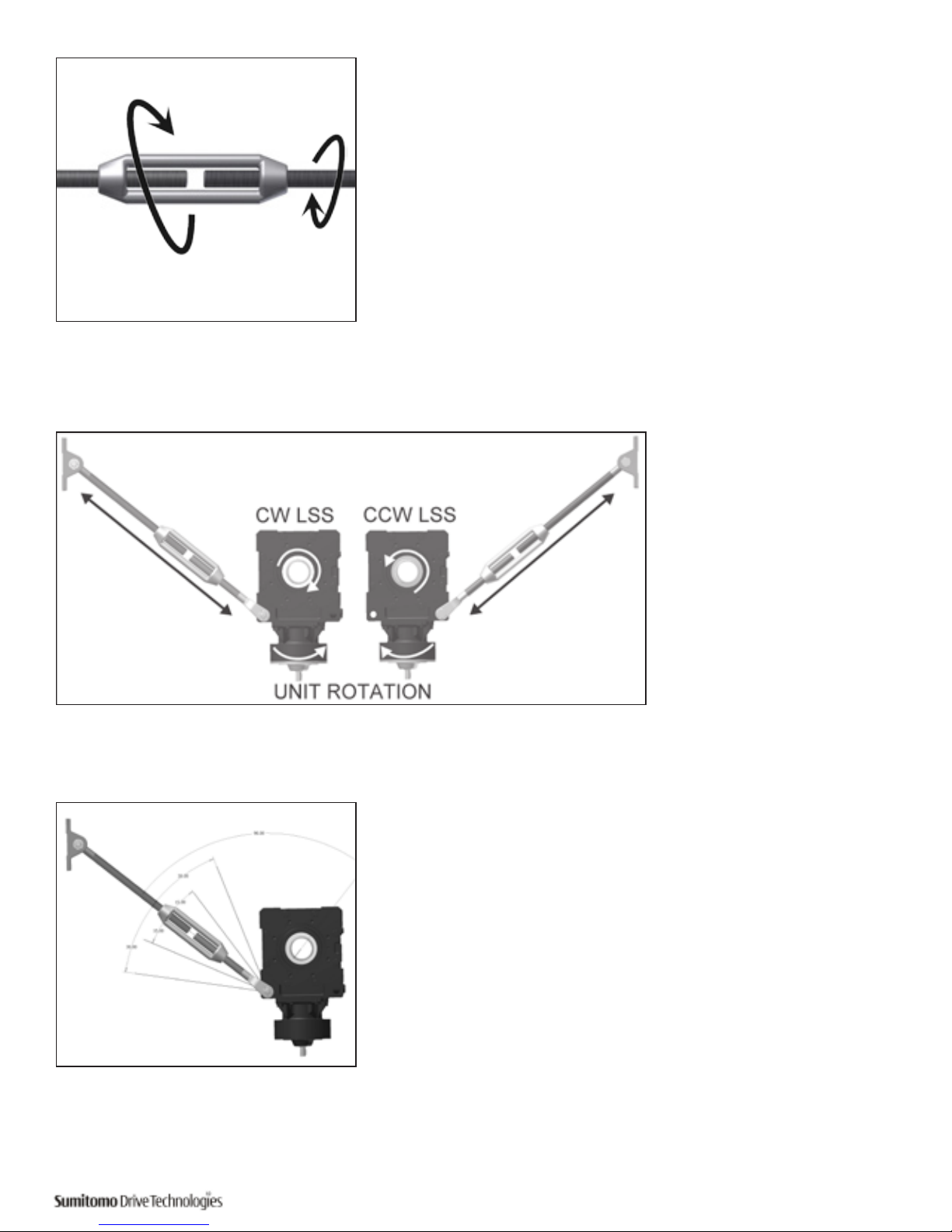
Install the turnbuckle onto the threaded extension rod (gearbox side)
and then threaded arm (foundation side) to the turnbuckle
If the assembly was supplied with hex nuts to secure the turnbuckle,
install the nuts loosely, ensuring the left hand nut is used on the
threaded arm, prior to installing the turnbuckle and threaded arm.
3
Position the torque arm so
it will be in tension during
unit operation and mount
the fulcrum mounting
bracket to suitable
structure or foundation.
Mounting hardware for
fulcrum mounting bracket
are NOT supplied by
Sumitomo.
4
Position the torque arm as close as possible to 90° relative to the unit
output bore / driven equipment shaft.
Sumitomo does not recommend the use of multiple torque arm
assemblies to achieve a greater overall length.
Page 16
14 Cyclo® BBB4 Quick Start Guide
5
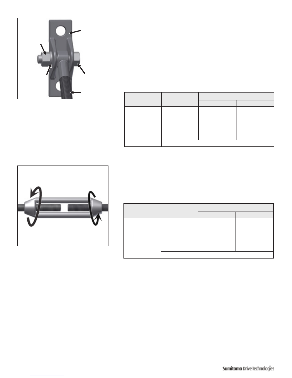
Assemble the threaded arm to the fulcrum mounting bracket,
as shown. Some adjustment of the turnbuckle may be required
to lengthen or shorten the overall length. Secure it with the
appropriate nut, bolt and lockwasher.
• Insert the bolt through the brackets and threaded arm
eyelet.
• Place the lockwasher on the bolt and secure with nut.
6
If turnbuckle hex nuts were supplied, secure the turnbuckle position
by adjusting the previously installed turnbuckle nuts.
BBB4 Size
Bracket
Bolt Size
[1]
Torque
ft-lb (Nm)
4A M16 x 65 152 - 167 (206 – 227)
4B M16 x 80 152 - 167 (206 – 227)
4C M16 x 80 152 - 167 (206 – 227)
4D M16 x 80 152 - 167 (206 – 227)
4E
M16 x 80 152 - 167 (206 – 227)
4F
Consult Factory
Table 7. Bolt Tightening Torque
BBB4 Size Nut Size
[1]
Torque
ft-lb (Nm)
4A M20 290 – 319 (392 – 431)
4B M24 507 - 558 (686 – 755)
4C M24 507 - 558 (686 – 755)
4D M24 507 - 558 (686 – 755)
4E
M24 507 - 558 (686 – 755)
4F
Consult Factory
Table 8. Nut Tightening Torque
Note: [1] Bolt ISO/JIS Class 8.8
Note: [1] Bolt ISO/JIS Class 8.8
Mounting
Bracket
Bolt
Threaded Arm
Lock Washer
Nut
Page 17
Quick Start Guide Cyclo® BBB4 15
Tie Rod Torque Arm Installation
Procedure
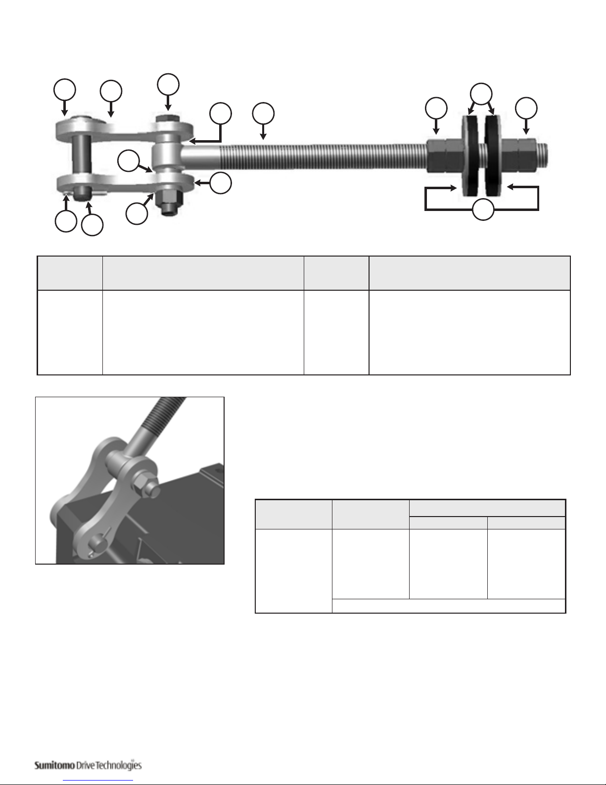
1
Assemble the torque arm mounting brackets or wishbone clevis to
the threaded arm, and attach the torque arm assembly to the bevel
housing, at the housing corner eyelet, using the pin and cotter pin.
Tighten mounting bolts according to the values listed in Table10.
• Insert the clevis pin through the brackets and housing
eyelet.
• Insert the cotter pin into clevis pin and secure assembly.
Item Description Item Description
1 Flat Washer 7 Rubber Bushing
2 (2) Mounting Brackets or (1) Clevis 8 Washers
3 Hex Bolt 9 Lock Washer
4 Spacer 10 Clevis Pin
5 Threaded Arm 11 Cotter Pin
6 Hex Hut
BBB4 Size
Bracket
Bolt Size
[1]
Torque
ft-lb (Nm)
4A 2 x M16 152 – 167 (206 – 227)
4B 2 x M20 290 – 319 (392 – 431)
4C 2 x M24 507 – 558 (686 – 755)
4D 2 x M24 507 – 558 (686 – 755)
4E
2 x M24 507 – 558 (686 – 755)
4F
Consult Factory
Table 10. Bracket Bolt Tightening Torque
Note: [1] Bolt ISO/JIS Class 8.8
1
2
3
5
6 6
7
8
4
2
4
9
10
11
Table 9. Tie Rod Type Torque Arm Parts
Figure 2. Tie Rod Type Torque Arm
Page 18
16 Cyclo® BBB4 Quick Start Guide
2
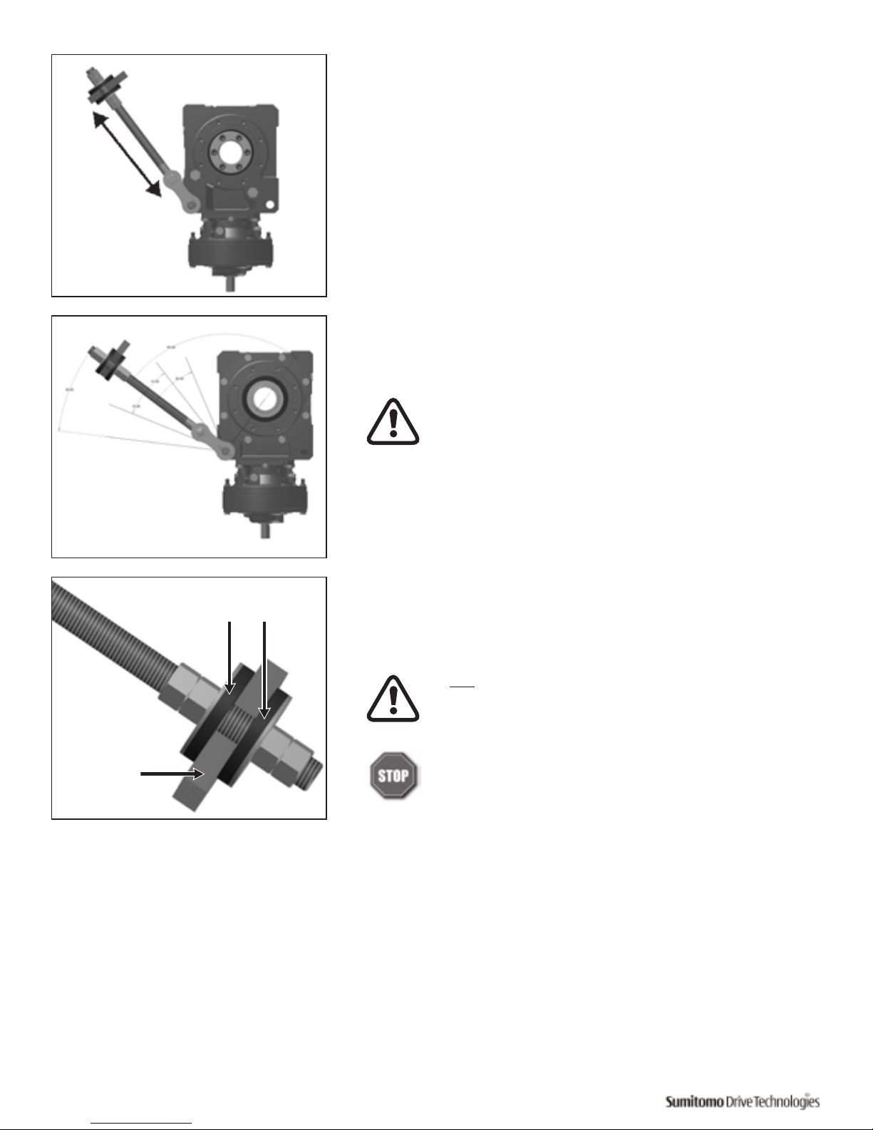
Position the torque arm so it will be in tension during unit operation.
3
Position the torque arm as close as possible to 90° relative to the unit
output bore / driven equipment shaft.
Sumitomo does not recommend the use of multiple torque
arm assemblies to achieve a greater overall length.
4
After inserting the torque rod into the mounting surface, carefully
tighten nuts on either side of torque rod.
Do not over tighten nuts. Tighten to point where rubber
bushings can still be hand rotated when the unit is turned
off.
Before starting unit, verify the following:
• The torque arm will be in tension when the unit is in
operation.
• The torque arm is aligned with the reducer housing.
• The torque arm is perpendicular to the axis of the
output / driven shaft.
• The threaded arm is not touching the reducer housing.
Customer
Mounting
Surface
Bushing are free to
rotate by hand
CW LSS
Unit Rotation
Page 19
Quick Start Guide Cyclo® BBB4 17
T-Type Torque Arm Installation
Procedure
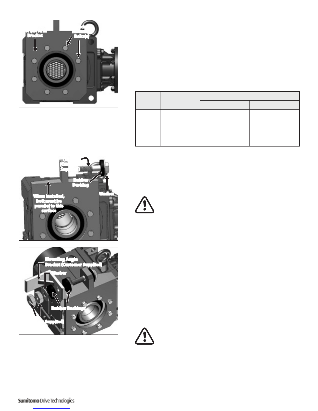
1
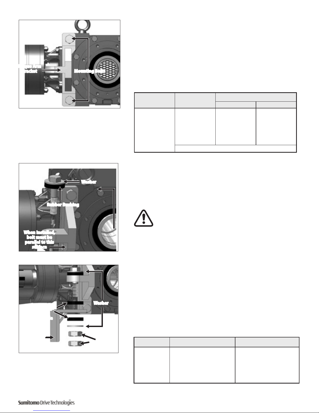
Attach the T-Type Torque Arm Bracket to the Cyclo® BBB4 using the supplied
mounting hardware.
Tighten mounting bolts according to the values listed in Table 7
2
Place washer and rubber bushing on bolt.
Insert torque arm bolt (supplied by customer) through mounting tab
on Banjo torque arm.
Make sure bolt is parallel to T-Type Torque Arm side
when fully installed.
3
Follow these steps to attach the mounting angle bracket:
• Place rubber bushing and mounting angle bracket on
the bolt.
• Verify that the mounting angle bracket hole is the correct
diameter for customer supplied bolt.
• Place remaining bushing, washer and two nuts on
the bolt.
Do not over-tighten nuts. Tighten to point where rubber
bushings can still be hand rotated.
Torque Arm
Bracket
Mounting Bolts
BBB4 Size
Bracket
Bolt Size
[1]
Torque
ft-lb (Nm)
4A 2 x M16 152 – 167 (206 – 227)
4B 2 x M20 290 – 319 (392 – 431)
4C 2 x M24 507 – 558 (686 – 755)
4D 2 x M30 1014 – 1115 (1373 – 1510)
4E
2 x M30 1014 – 1115 (1373 – 1510)
4F
T-Type Not Available
Note: [1] Bolt ISO/JIS Class 8.8
Table 11. T-Bracket Bolt Torques
Washer
Rubber Bushing
When installed,
bolt must be
parallel to this
surface
Washer
Rubber Bushings
Mounting Angle
Bracket
(Customer
Supplied)
Nuts
(Customer Supplied)
Unit Size Bracket Tab Bore
Typical Bolt Size
[1]
4A Ø18mm M16
4B Ø18mm M16
4C Ø22mm M20
4D Ø26mm M24
4E Ø33mm M30
Note
[1]
Bolt class should be greater or equal to ISO/JIS Class 8.8. Application with
multiple start/stops and/or shock loading should use ISO/JIS 10.9 at a minimum.
Table 12. T-Bracket Mount Dimensions
Page 20
18 Cyclo® BBB4 Quick Start Guide
Top View
4
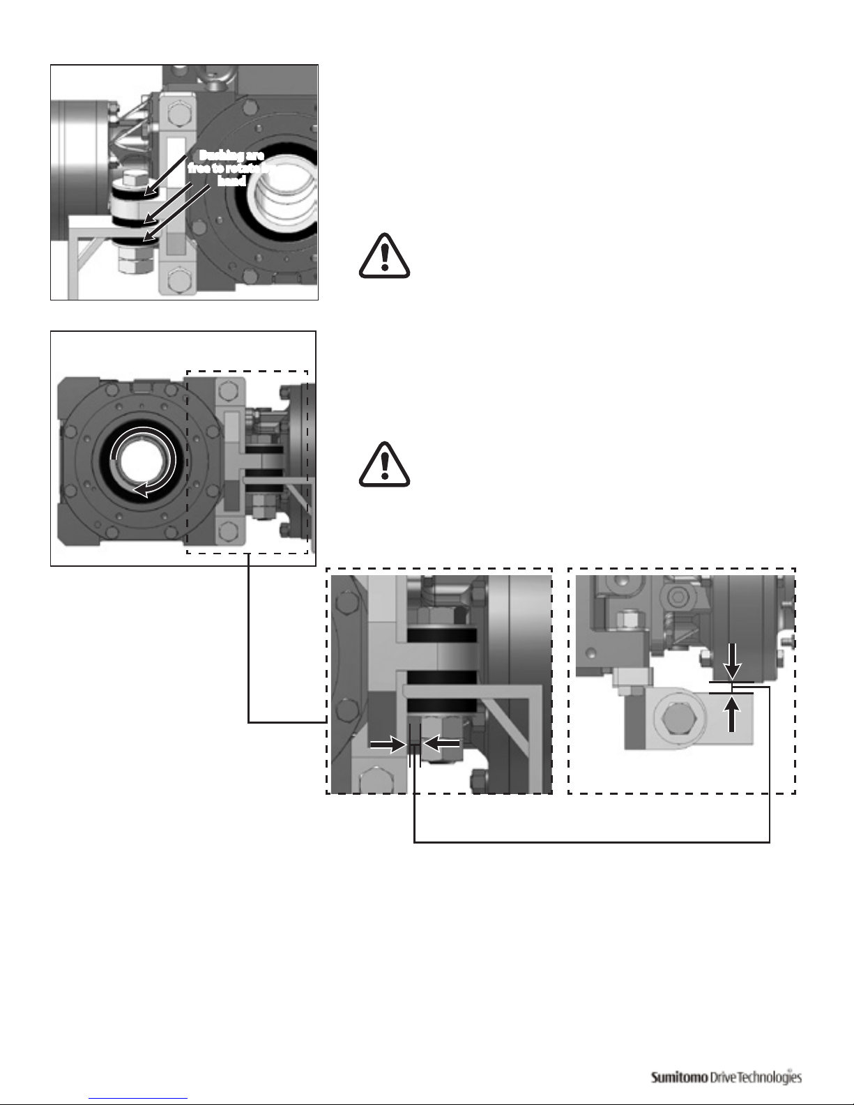
Confirm that the rubber bushings can still be rotated by hand. This
indicates the bushing has not been over-tightened.
Compressed bushings will not allow the bushings to properly absorb
the loads of the shaft mounted gearbox. This can lead to premature
failure.
Mounting angle bracket must be secured to the machine
structure.
5
Confirm the mounting angle bracket does not interfere with the
torque arm. There should be no metal-to-metal contact between
the two during a complete revolution of the driven equipment.
Metal-to-Metal contact between these two components
may lead to catastrophic failure of the reducer/ gearmotor.
Bushing are
free to rotate by
hand
Page 21
Quick Start Guide Cyclo® BBB4 19
Flange Mount (Banjo) Type Torque Arm
Installation Procedure
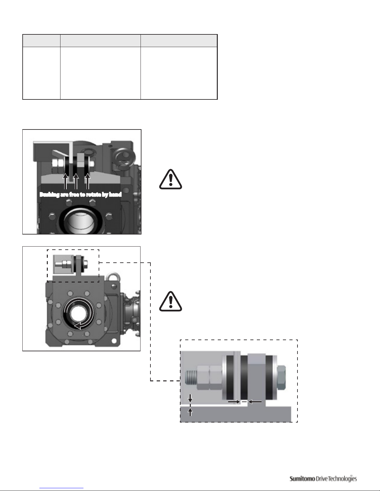
1
Attach the Flange Mount (Banjo) Torque Arm Bracket to the Cyclo®
BBB4 using mounting hardware.
2
Place washer and rubber bushing on bolt. Insert torque arm bolt
(supplied by customer) through mounting tab on Flange Mount
(Banjo) type torque arm.
Make sure bolt is parallel to Flange Mount (Banjo) Type
torque arm surface when fully installed.
3
Follow these steps to attach the torque arm to mounting structure or
mounting angle bracket (customer supplied):
• Verify that the mounting structure or mounting angle
bracket hole is the correct diameter.
• Place rubber bushing and mounting angle bracket on
bolt.
• Ensure the bolt passes through mounting structure or
mounting angle bracket hole.
• Place remaining bushing, washer and two nuts on the
bolt.
Do not over-tighten nuts. Tighten to point where
rubber bushings can still be hand rotated.
Unit
Size
Bracket
Bolt Size
[1]
Torque
ft-lb (Nm)
4A 8 x M10 34 – 38 (46 – 51)
4B 8 x M12 59 – 65 (80 – 88)
4C 8 x M16 152 – 167 (206 – 227)
4D, 4E 8 x M20 290 – 319 (392 – 431)
4F 8 x M24 507 – 558 (686 – 755)
Table 13. Flange Mount (Banjo) Torque Arm Bolt Tightening
Torques
Bracket
Mounting
Bolts(s)
Torque Arm
Bracket
When installed,
bolt must be
parallel to this
surface
Washer
Rubber
Bushing
T/A Bolt
(Customer
Supplied)
Mounting Angle
Bracket (Customer Supplied)
Washer
Rubber Bushings
Nuts
(Customer Supplied)
Note: [1] Bolt ISO/JIS Class 8.8
Page 22
20 Cyclo® BBB4 Quick Start Guide
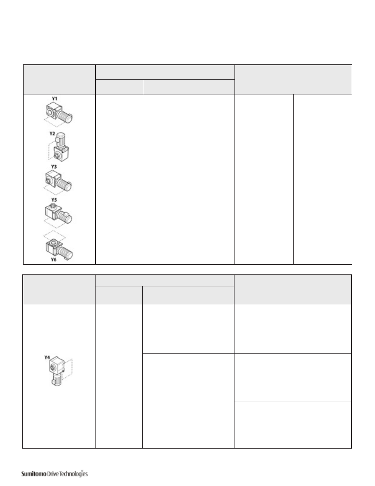
4
Confirm that the rubber bushings can still be rotated by hand. This
indicates the bushing has not been over-tightened.
Compressed bushings will not allow the bushings to
properly absorb the loads of the shaft mounted gearbox.
This can lead to premature failure.
If used, the mounting angle bracket must be secured to the
machine structure.
5
Confirm the mounting angle bracket does not interfere with the
torque arm. There should be no metal-to-metal contact between the
two during a complete revolution of the driven equipment.
Metal-to-Metal contact between these two components
may lead to catastrophic failure of the reducer/gearmotor.
Unit Size Bracket Tab Bore
Typical Bolt Size
[1]
4A Ø18mm M16
4B Ø18mm M16
4C Ø22mm M20
4D Ø26mm M24
4E Ø33mm M30
4F Ø39mm M36
Table 14. Flange Mount (Banjo)Torque Arm Bolt Dimensions
Completed Assembly
Bushing are free to rotate by hand
During full rotation of driven shaft, there must be no metal-to-metal contact between mounting angle bracket and
torque arm.
Note
[1]
Bolt class should be greater or equal to ISO/JIS Class 8.8. Application with
multiple start/stops and/or shock loading should use ISO/JIS 10.9 at a minimum.
Page 23
Quick Start Guide Cyclo® BBB4 21
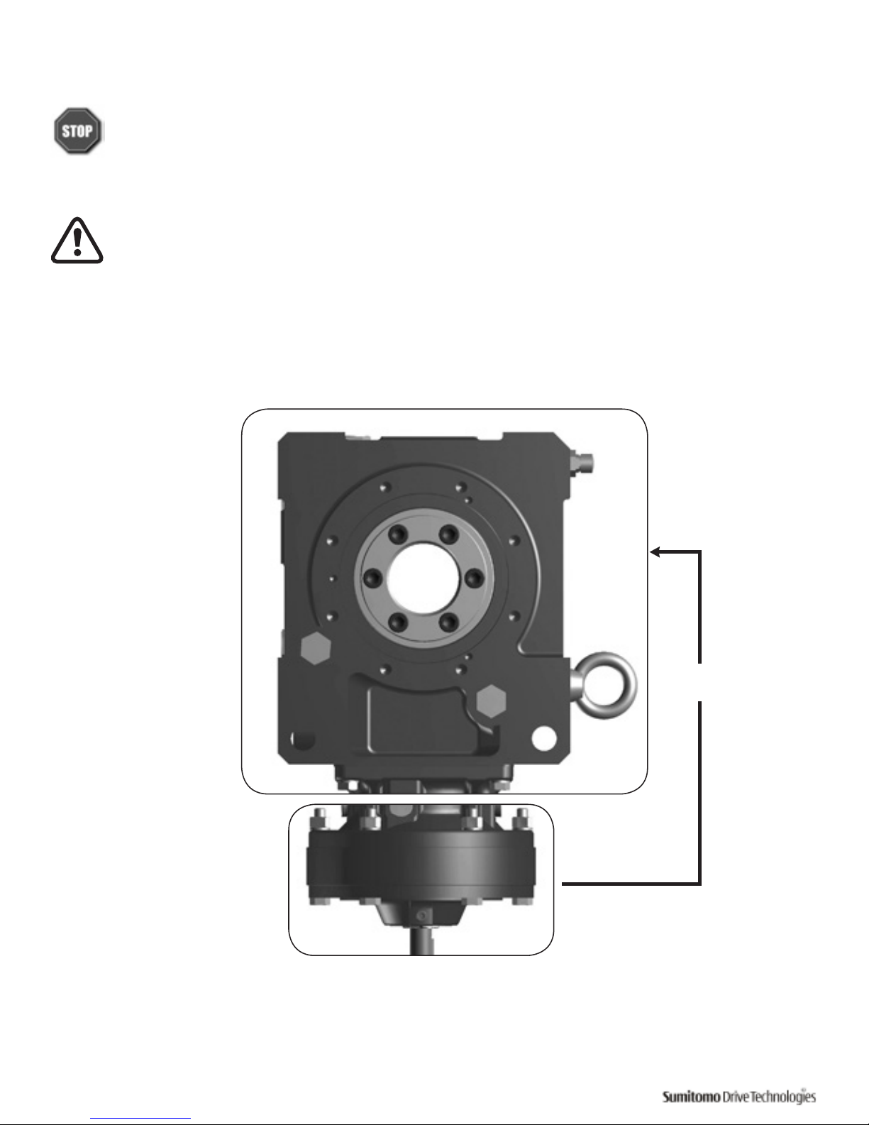
Standard Lubrication Method
Using the model number and mounting configuration, refer to Tables 15 and 16 to determine the unit’s
lubrication method.
Mounting Configuration
Unit Size
Lubrication Method
Bevel Gear Size Cyclo® Size
4A - 4F
100, 105,
110, 115,
120, 125,
140, 145
160, 165,
170. 175,
180, 185,
190, 195
10DA, 12DA,
12DB, 14DA,
14DB, 14DC,
16DA, 16DB,
17DA, 17DB,
17DC
Complete Unit
(Bevel Gear Portion
and Cyclo® Portion)
Common Oil Sump
Mounting Configuration
Unit Size
Lubrication Method
Bevel
Gear Size
Cyclo® Size
4A-4F
100, 105,
110, 105,
120, 125,
140, 145
10DA, 12DA, 12DB
Cyclo® Portion
Maintenance Free
Grease
[1]
Bevel Gear Portion Oil
140, 145,
160, 165,
170, 175
180, 185,
190, 195
12DA, 12DB ,
14DA, 14DB, 14DC,
16DA, 16DB,
17DA,17DB, 17DC,
18DA, 18DB,
19DA, 19DB
Cyclo® Portion Grease
[2]
Bevel Gear Portion Oil
Notes: [1] Maintenance Free Grease: the input Cyclo® portion is grease lubricated as standard from the factory and usually does not require replacement or replenishment.
[2] Grease: the input Cyclo® portion is grease lubricated as standard from the factory. Please refer to Tables 16 and 17 for the proper grease replenishment and change
interval.
Table 15. Lubrication Method for Configurations Y1, Y2, Y3, Y5, Y6
Table 16. Lubrication Method for Configurations Y4
Page 24
22 Cyclo® BBB4 Quick Start Guide
Lubrication
Sumitomo Cyclo® BBB4s are typically shipped from the factory without lubricating oil, unless the customer
specified otherwise when the unit was ordered.
The unit must contain the correct type and amount of lubrication before operating.
For all Y4 motor down mounting configurations, the Cyclo® portion is filled at the factory with grease. For
these units, the Cyclo® portion does not need to be filled with lubricant before start-up. The Bevel Gear
portion of models built for the Y4 mounting configuration still requires filling with gear oil before start-up.
Refer to the Lubrication Method section for details.
For the Cyclo®BBB4 built for the Y4 mounting configuration, the Cyclo® and the bevel gear portions must be
filled with lubricant separately and maintained separately. Lubricant does not flow from one section to the
other.
Separate
Lubrication
Bevel Gear Portion
Cyclo® Input Portion
Figure 3. Cyclo® BBB4 in Y4 Assembly
Page 25

Quick Start Guide Cyclo® BBB4 23
Bevel Gear Portion and Cyclo® Portion Lubricants
Recommended Oils
Table 17, Recommended Oils, lists the oils that may be used to lubricate the Bevel Gear portion of the unit. These
oils may also be used in the Cyclo® portion if it is oil lubricated.
Ambient
Temp. °F (ºC)
Manufacturer
Gulf Oil Exxon Oil Mobil Oil Shell Oil Caltex Oil BP Oil Idemitsu
14° – 41°F
(-10º – 5ºC)
EP Lubricant
HD 68
—
Mobilgear 600
XP 68
(ISO VG 68)
Omala S2 G 68 —
Energol
GR-XP 68
Daphne
Mechanic
Oil 68
32° – 95°F
(0º – 35ºC)
EP Lubricant
HD 100
HD150
Spartan
EP 100
EP 150
Mobilgear 600
XP 100, 150
(ISO VG 100,
150)
Omala S2 G
100 150
Meropa
100
150
Energol
GR-XP 100
GR-XP 150
Daphne
Mechanic Oil
100, 150
86° – 122°F
(30º – 50ºC)
EP Lubricant
HD 220
HD 320
HD 460
Spartan
EP 220
EP 320
EP 460
Mobilgear 600
XP 220, 320,
460
(ISO VG 220,
320, 460)
Omala S2 G
220 320 460
Meropa
220
320 460
Energol
GR-XP 220
GR-XP 320
GR-XP 460
Daphne
Mechanic
Oil 220, 320,
460
• Use lubricants with low viscosity for operation during winter or at relatively low temperatures.
• Use a lubricant with a viscosity within the range listed in Table 18, Recommended Oil Viscosity.
• Consult a local distributor, nearest authorized agent or Sumitomo directly when the unit will be operated
in ambient temperatures other than 14° – 104°F (-10° – 40°C). Special unit modifications may be necessary.
Minimum allowable viscosity 15 cSt (mm2/s) or more at operating temperature
Viscosity that ensures oil film strength
adequate for load transmission.
Maximum allowable viscosity 4300 cSt (mm2/s) max.
Viscosity that permits start-up of
Buddybox®
Table 17. Recommended Oils.
Table 18. Recommended Oil Viscosity
Cyclo® Portion Approved Greases
Table 19, Cyclo® Portion Approved Greases, lists the greases that may be used to lubricate the Cyclo® portion if
grease is the specified lubrication method (refer to the Lubrication Method section for details).
Table 19. Cyclo® Portion Approved Greases
Ambient Temp.
°F (ºC)
Overall
Reduction Ratio
All Unit Sizes
14° – 122°F
(-10º – 50ºC)
11:1 through 18:1 Shell Gadus S2 V220 NLGI 00
19:1 and higher ExxonMobil Unirex N2 grease
Cyclo® portions have unique operating characteristics that require specific lubricant properties. Please consult
Sumitomo if alternate lubricants are required.
Page 26
24 Cyclo® BBB4 Quick Start Guide
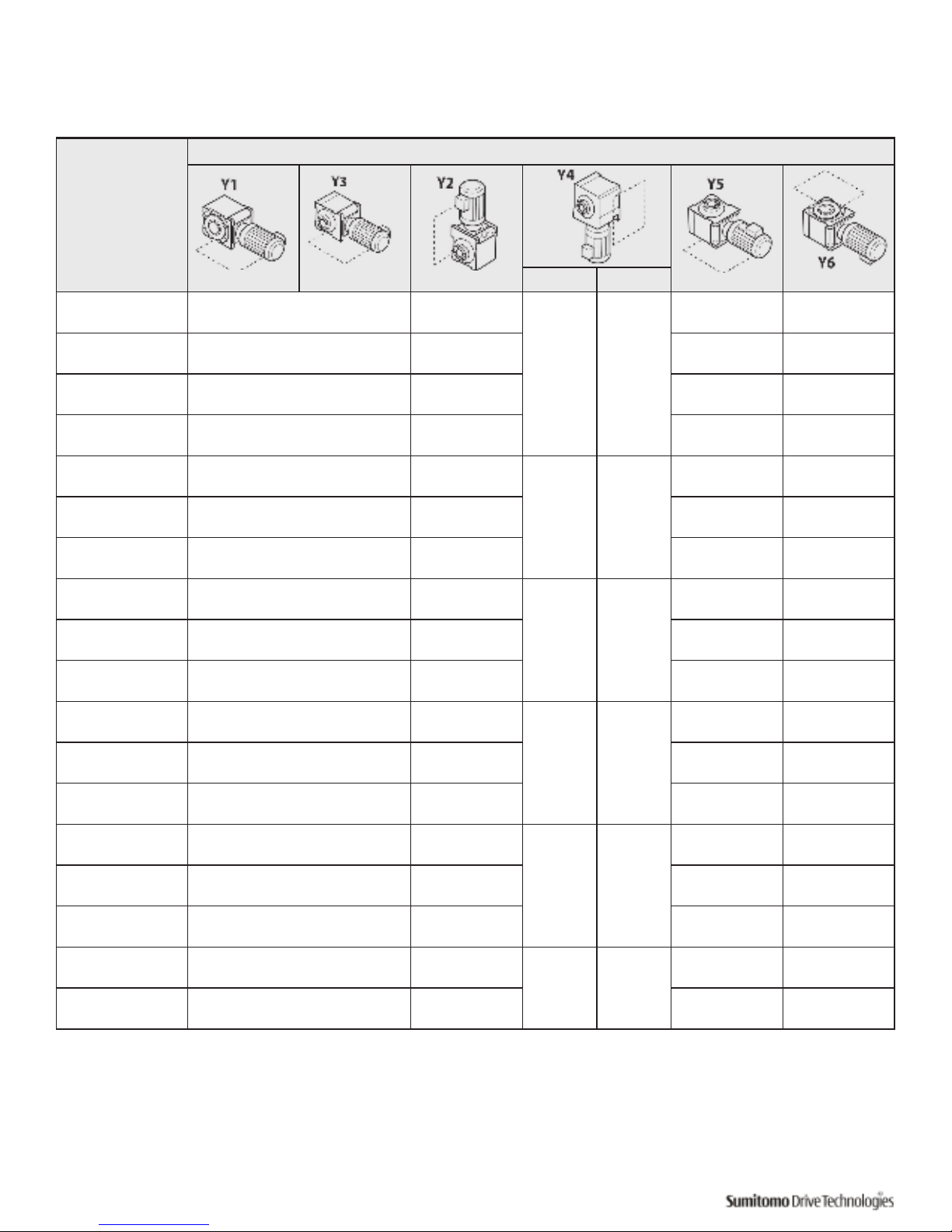
Oil Quantities
Table 20. Single Reduction Approximate Oil Quantity
Units: US liquid gallon (liter) Note: Output = Bevel Gear Portion Input = Cyclo® Portion
Bevel Gear
Unit Size
Mounting Configuration
Output Input
4A10
0.43
(1.62)
0.84
(3.17)
0.30
(1.13)
Grease
0.36
(1.36)
0.49
(1.84)
4A11
0.44
(1.66)
0.86
(3.26)
0.37
(1.40)
0.50
(1.88)
4A12
0.45
(1.71)
0.88
(3.35)
0.38
(1.45)
0.51
(1.93)
4A14
0.50
(1.91)
1.00
(3.77)
0.44
(1.65)
0.56
(2.13)
4B12
0.87
(3.29)
1.72
(6.50)
0.45
(1.72)
Grease
0.88
(3.34)
0.85
(3.23)
4B14
0.92
(3.49)
1.84
(6.97)
0.94
(3.54)
0.91
(3.43)
4B16
1.04
(3.92)
2.01
(7.61)
1.05
(3.97)
1.02
(3.86)
4C14
1.46
(5.52)
2.94
(11.1)
0.72
(2.72)
Grease
1.40
(5.30)
1.55
(5.88)
4C16
1.57
(5.96)
3.11
(11.8)
1.52
(5.74)
1.67
(6.32)
4C17
1.67
(6.34)
3.31
(12.5)
1.62
(6.12)
1.77
(6.70)
4D16
2.66
(10.1)
5.26
(19.9)
1.22
(4.61)
Grease
2.56
(9.69)
2.76
(10.4)
4D17
2.75
(10.4)
5.41
(20.5)
2.65
(10.0)
2.85
(10.8)
4D18
2.83
(10.7)
5.54
(21.0)
2.72
(10.3)
2.93
(11.1)
4E17
3.85
(14.6)
7.60
(28.8)
1.65
(6.26)
Grease
3.45
(13.1)
4.24
(16.1)
4E18
3.88
(14.7)
7.70
(29.1)
3.49
(13.2)
4.28
(16.2)
4E19
4.14
(15.7)
8.04
(30.4)
3.75
(14.2)
4.54
(17.2)
4F18
5.28
(20.0)
10.41
(39.4)
1.92
(7.28)
Grease
4.89
(18.5)
5.65
(21.4)
4F19
5.50
(20.8)
10.74
(40.6)
5.10
(19.3)
5.86
(22.2)
Page 27
Quick Start Guide Cyclo® BBB4 25
Bevel Gear
Unit Size
Mounting Configuration
Output Input
4A10DA
0.44
(1.65)
0.84
(3.20)
0.30
(1.13)
Grease
0.37
(1.39)
0.49
(1.87)
4A12DA
0.46
(1.74)
0.89
(3.38)
0.39
(1.48)
0.52
(1.96)
4A12DB
0.47
(1.78)
0.90
(3.43)
0.40
(1.52)
0.53
(2.00)
4B12DA
0.88
(3.32)
1.73
(6.53)
0.45
(1.72)
Grease
0.89
(3.37)
0.86
(3.26)
4B12DB
0.89
(3.36)
1.73
(6.57)
0.90
(3.41)
0.87
(3.30)
4B14DA
0.93
(3.52)
1.85
(7.00)
0.94
(3.57)
0.91
(3.46)
4B14DB
0.94
(3.56)
1.86
(7.04)
0.95
(3.61)
0.92
(3.50)
4C14DA
1.47
(5.55)
2.95
(11.2)
0.72
(2.72)
Grease
1.41
(5.33)
1.56
(5.91)
4C14DB
1.48
(5.59)
2.96
(11.2)
1.42
(5.37)
1.57
(5.95)
4C14DC
1.49
(5.64)
2.97
(11.3)
1.43
(5.42)
1.59
(6.00)
4C16DA
1.59
(6.03)
3.13
(11.8)
1.53
(5.81)
1.69
(5.39)
4C16DB
1.61
(6.08)
3.14
(11.9)
1.55
(5.86)
1.70
(6.44)
4C17DA
1.69
(6.41)
3.33
(12.6)
1.63
(6.19)
1.79
(6.77)
4D16DA
2.68
(10.1)
5.27
(20.0)
1.22
(4.61)
Grease
2.58
(9.76)
2.77
(10.5)
4D16DB
2.69
(10.2)
5.29
(20.0)
2.59
(9.81)
2.79
(10.6)
4D17DB
2.78
(10.5)
5.44
(20.6)
2.68
(10.2)
2.88
(10.9)
4D17DC
2.82
(10.7)
5.48
(20.7)
2.72
(10.3)
2.91
(11.0)
4E17DA
3.86
(14.6)
7.62
(28.8)
1.65
(6.26)
Grease
3.47
(13.1)
4.26
(16.1)
4E17DB
3.88
(14.7)
7.63
(28.9)
3.48
(13.2)
4.27
(16.2)
4E17DC
3.91
(14.8)
7.67
(29.0)
3.52
(13.3)
4.31
(16.3)
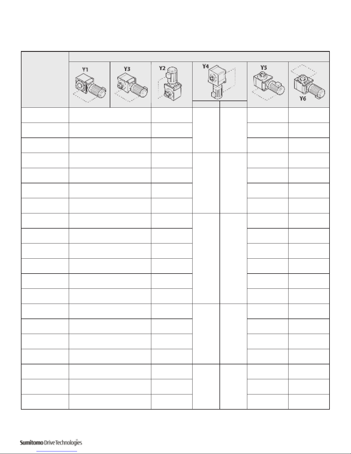
Oil Quantities
Table 21. Double Reduction Approximate Oil Quantity
Units: US liquid gallon (liter) Note: Output = Bevel Gear Portion Input = Cyclo® Portion
Page 28

26 Cyclo® BBB4 Quick Start Guide
Oil Supply Procedures
• Always stop the unit before adding oil
• Oil level may drop during operation, depending on the oil viscosity, temperature and direction of
rotation. Additional oil is not necessary. Check the oil level when the unit is stopped to ensure that it has
the correct amount of oil.
• It may take some time for the oil to settle when the oil viscosity is high. Be careful not to add too much oil.
• There may be two different oil fill locations for some combinations; refer to oil fill/ drain locations figure
for details.
• Consider implementing an oil analysis program to ensure lubricant continues to operate at peak
performance. Follow your lubrication provider’s oil analysis recommendations to ensure reducer
performance.
• Always consult factory and warehouses for overhaul of gearmotors and reducers. Familiarity with Cyclo®
products is necessary for proper overhaul.
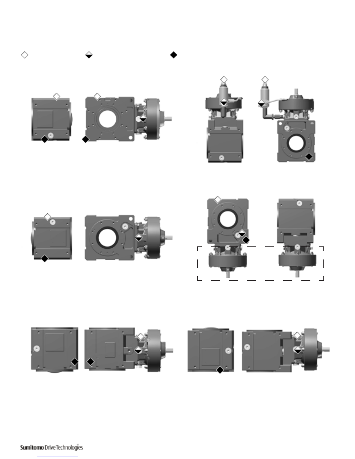
1. Remove the oil fill plug, as referenced in Figure 4.
2. Slowly add oil while checking the level through the oil gauge.
3. After the oil has settled, make sure the level is midway between the high and low marks on the oil gauge.
4. Insert the oil fill plug after wrapping it with sealing compound or tape.
Task Change interval Conditions of use
Supply of Oil At installation All
Oil Change
First Change
500 hrs operation or 6 months,
whichever comes first.
All
Second change and thereafter
2500 hrs operation or 6 months,
whichever comes first.
When case oil temperature is
158° F (70° C) or higher
5000 hrs operation or 1 year, whichever
comes first.
When case oil temperature is
lower than 158° F (70° C)
Table 22. Oil Change Intervals
Page 29
Quick Start Guide Cyclo® BBB4 27
Y1
Y2
Y3
Y5
Y6
Figure 4. Oil Fill/Drain Locations
Oil Fill/Drain Locations
Oil ller plug Oil level (Oil gauge) Oil drain plug
Y4
Grease
Page 30

28 Cyclo® BBB4 Quick Start Guide
Grease Quantities
• Grease quantities listed in this section are for the Cyclo® portion of the reducer/gearmotor.
• The Bevel portion is always oil lubricated unless otherwise specified at time of order entry.
• Refer to the Bevel Gear Portion and Cyclo® Portion Recommended Oils section for Bevel portion oil
quantities.
The Cyclo® (input) portion of all double reduction units is grease lubricated at the factory. Additional grease is not
required prior to initial startup. Refer to Cyclo® BBB4 Operating and Maintenance Manual for grease quantity.
Motor Wiring
This section details wiring for standard Sumitomo three-phase motors and brakemotors.
The motor diagram found inside Sumitomo supplied motor conduit box cover is correct. If using a
motor manufactured by a company other than Sumitomo, please refer to that manufacturer’s instruction
manual for wiring, operating and maintenance details. When wiring motors into the power supply,
Sumitomo recommends the use of terminal rings to facilitate the connection.
• Do not handle the unit when cables are live. Be sure to turn-off the power; otherwise electric shock may
result.
• Connect the power cables to the unit according to the connection diagram shown inside the terminal box
or in the maintenance manual; otherwise electric shock or fire may result.
• Correctly ground the grounding bolt; otherwise electric shock may result.
• Keep all wiring and electrical parts dry and moisture free.
• Follow local electrical codes and regulations when wiring; otherwise burning, electrical shock, injury and/
or fire may result.
• The motor is not equipped with an overload device. Sumitomo strongly recommends that another
protective device (i.e.: ground fault interrupters, etc.), in addition to an overload device, be installed in
order to prevent burning, electric shock, personal injury and/or fire.
• For Single Phase motors, exercise case so as to not damage the vinyl cover of the starting capacitor,
otherwise shock may result.
• For Brakemotors, do not electrify a brake coil continuously when the motor is stopped otherwise the
brake coil may burn and fire may result.
• For Brakemotors, install the rectifier where the temperature is less than 140°F (60°C).
• Long wires cause the voltage to drop. Select cables with appropriate diameter so that the voltage drop
will be less than 2%.
• After wiring the motor, check that the terminal box mounting bolts are tight.
Motor Protection
• Use a molded case circuit breaker for protection against short circuit.
• Use an overload protection device that protects the unit against voltage surges
Page 31

Quick Start Guide Cyclo® BBB4 29
Notes:
Page 32

U.S. Sales and Support
Chicago (Midwest)
Sumitomo Machinery Corporation of America
175 West Lake Dri ve
Glendale Heights, IL 60139
Tel: +1-630-752-0200 • 1-800-SMC YCLO
Fax: +1- 630-752- 0208
Los Angeles (West)
Sumitomo Machinery Corporation of America
2375 Railroad Street
Corona , CA 92880-5 411
Tel: +1-951-340 -4100 • 1-800-SMCYCLO
Fax: +1-9 51-340- 4108
Canada
Toronto (East)
SM-Cyclo of Canada, Ltd.
1453 Cornwall Rd,
Oakville, Ontario, Canada L6J 7T5
Tel: +1-905-469-1050 • Fax: 905-469-1055
Vancouver (West)
SM-Cyclo of Canada, Ltd.
740 Chester Road, Annacis Island, Delta
B.C., Canada V3M 6J1
Tel: +1-604-525-5403 • Fax: 604-525-0879
Montreal
SM-Cyclo of Canada, Ltd.
2862 Blvd. Daniel-Johnson
Laval, Quebec, Canada H7P 5Z7
Tel: +1-450-686-8808 • Fax: 450-686-8000
Mexico
Monterrey
SM- Cyc lo de Mexico, S .A. de C.V.
Av. Desarr ollo No. 541
Parque Industrial Finsa
Guada lupe, NL, Mex ico CP 67114
Tel: +52-81-8144-5130 • Fax: +52-81-8369-3699
Mexico City
SM- Cyc lo de Mexico, S .A. de C.V.
Priva da Ceylan No. 59- B Bis
Colonia Industrial Vallejo
Delegacion Azcapotzalco, DF Mexico 02300
Tel: +52-55-5368-7172 • Fax: +52-55-5368-6699
Guadalajara
SM- Cyc lo de Mexico S. A. de C.V.
Calle B roca No. 2605, Bo dega 4
Parque Alamo Industrial
Tlaquepaque , Jal, Mexico 44490
Tel: +52-33-3675-43-69 • Fax: +52-33-3675-4418
Brazil
São Paul o
Sumito mo Indústri as Pesadas do Br asil Ltda.
Rod. Ar chimedes L ammoglia (SP- 075) - Km 26
Jardim Oliveira - Itú, SP, 13312-500 Brazil
Tel: +55-11-4 403-9292 • Fax: +55-11-4403-9292
Chile
Santiago
SM Cyclo de Chi le Ltda.
San Pab lo 3507
Comuna d e Quinta Norm al - Santiago, Ch ile
Tel: +562-892-7000 • Fax: +562-892-7001
Antofagasta
SM Cyclo de Chi le Ltda.
Calle 8 , Manzana N2, Sit io 1
Sec tor La Negra - An tofagasta , Chile
Tel: +565-556-1611 • Fax: +565-556-1616
Concepción
SM Cyclo de Chi le Ltda.
Camin o a Coronel Km 10, #5580, M odulo 3-A
Comuna: S an Pedro de la Paz – C oncepción, C hile
Tel: +41-246-98-06/07 • Fax: +41-246-98- 08
Argentina
Buenos Aires
SM-Cyclo de Argentina SA
Ing. Delpini # 2236
Area de Promocion el Triangulo, Par tido Malvinas
Argentinas
Grand Bourg, Buenos Aires, Argentina B1615KGB
Tel: +54-11-4765-5332 • Fax: +54-11-4765-5517
Europe
Austria
Belgium
France
Germany
Italy
Spain
Sweden
United Kingdom
Asia
China
Hong Kong
Indonesia
Korea
Malaysia
Philippines
Singapore
Taiwan
Thailand
Vietnam
Other Locations
Australia
India
New Zealand
World Headquarters
Japan
Sumitomo Heavy Industries, Ltd.
Power Transmission & Controls Group
ThinkPark Tower, 1-1, Osaki 2-chome,
Shinagawa-ku, Tokyo 141-6025 Japan
Tel: +81-367-37-2511 • Fax: +81-368-66-5160
Manual 13.604.61.002
©2016 Sumitomo Machinery Corporation of America Printed in USA
WORLDWIDE LOCATIONS
Sumitomo Machinery Corporation of America
Headquarters & Manufacturing
4200 Holland Boulevard
Chesapeake, VA 23323
Tel: 757-485-3355 • 1-800-SMCYCLO
Fax: 757-485-7490
www.sumitomodrive.com • E-mail: [email protected]
 Loading...