

Sumitomo Cyclo BBB Operation And Maintenance Manual
N
n
T
L
A
C
0
–
M
J
d
S
S
2
FI
AL OPERA
ION AND M
ORDEN D
FM
INTENANC
E COMPRA
TECHNOL
E MANUAL
H336073-P
OGIES PRO
MINA MINI
031/A 45011
ECT B6042
TRO HALE
90525
PROJECT
FMCTech
ologiesChile
tda.Callao#2
970Oficina7
4EdificioStu
ioLasCondes
Fono:56‐2‐2
320825
Operation and
Maintenance Manual
Cyclo
Bevel Buddybox
Manual 13.601.60.005T •May 09
®
BBB
Operation and
Maintenance Manual
Table of Contents
Taper-Grip® Bushing. . . . . . . . . . . . . . . . . . . . . . . . . . . . . . 1
Parts List . . . . . . . . . . . . . . . . . . . . . . . . . . . . . . . . . . . . . . . . 2
Motor Characteristics. . . . . . . . . . . . . . . . . . . . . . . . . . . . . 6
Brakemotor Characteristics . . . . . . . . . . . . . . . . . . . . . . . 7
Standard Wiring. . . . . . . . . . . . . . . . . . . . . . . . . . . . . . . . . . 9
Lubrication . . . . . . . . . . . . . . . . . . . . . . . . . . . . . . . . . . . . . 10
Installation . . . . . . . . . . . . . . . . . . . . . . . . . . . . . . . . . . . . . 12
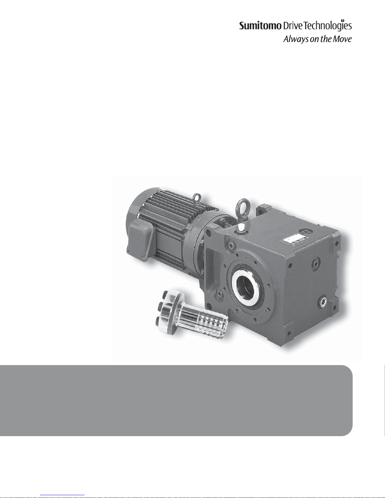
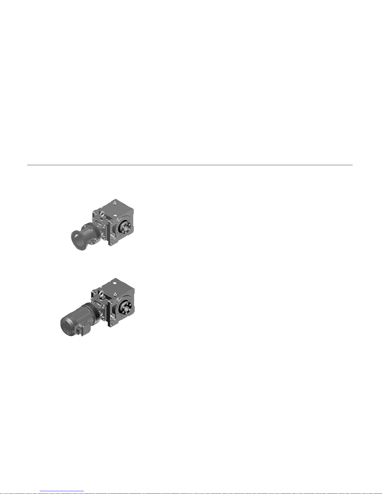
Cyclo BBB
Speed Reducers and Gearmotors
featuring Keyless Taper-Grip® Bushing
BEVEL BUDDYBOX

Cyclo®BBB
Notes
Inch Tolerance Metric mm Tolerance*
111/16 - 115/16 +.003 /.001 40-50 .064 /.025
2 - 27/16 +.003 /.001 50-65 .076 /.030
21/2 - 37/16 +.003 /.001 65-80 .076 /.030
31/2 - 315/16 +.003 /.001 80-100 .090 /.036
Shaft Dia. Tolerance
3
/4" - 11/8" +0 - .005"
13/16" - 2" +0 - .006"
21/16" - 31/8" +0 - .007"
33/16" - 43/4" +0 - .008"
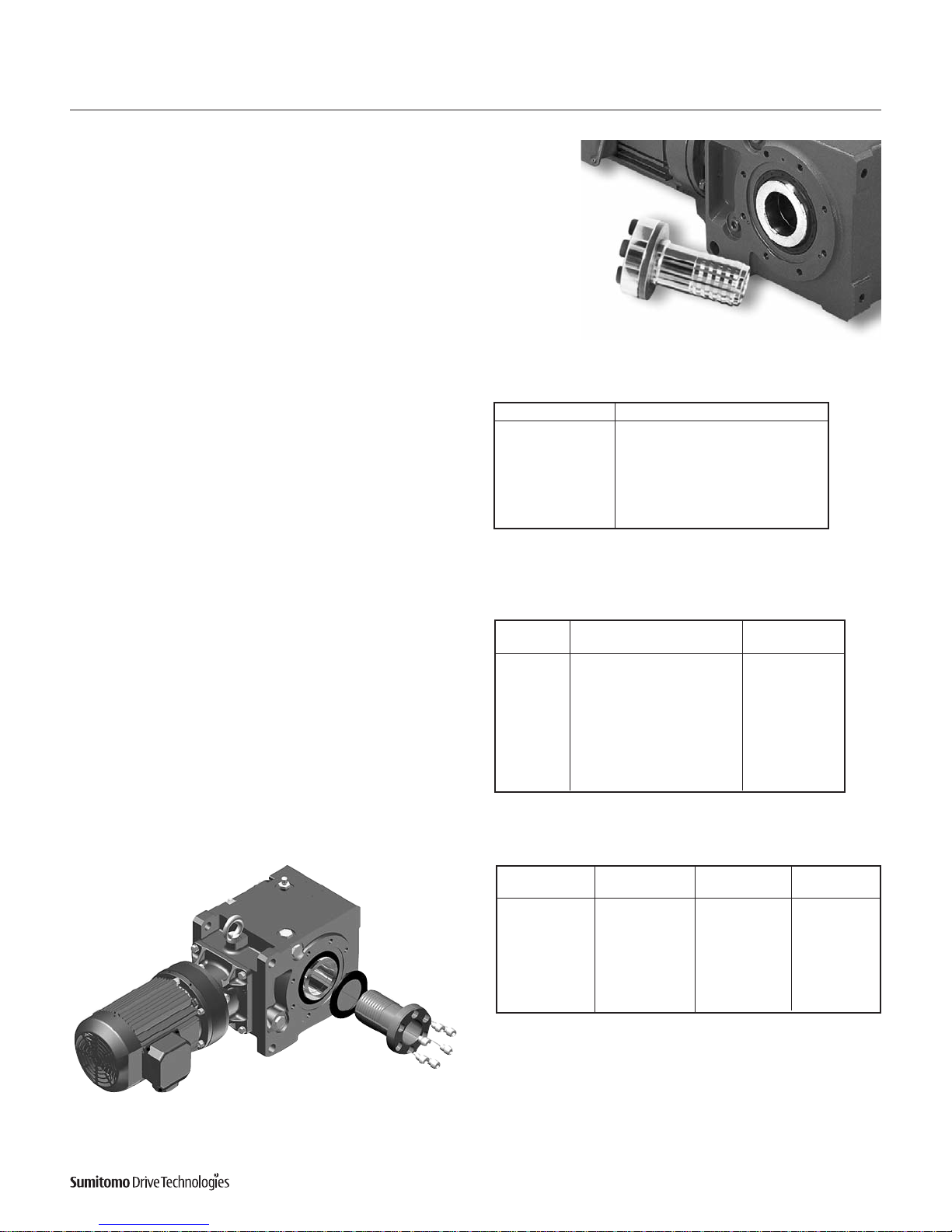
Taper Grip® Bushing
Size
Screw Size Screw Torque
Qty. & Code lb. ft.
A 6 X M12 112E7003 56
B 6 X M12 112E7003 104
C 6 X M16 112G7003 185
D 6 X M16 112G7003 185
E 8 X M16 112G7003 185
Figure 1. PERMISSIBLE SHAFT TOLERANCE
Figure 2. BUSHING SCREW TIGHTENING TORQUES
*Metric Tolerances are F8.
NOTE: Shaft runout TIR should be no greater than .001".
Figure 3. BUSHING BORE TOLERANCES
NOTE: Shaft runout TIR should be no greater than .001".
NOTE: Similar to all shrink disk type devices. It is essential to properly
assemble and tighten the mounting bolts. Carefully follow the Sumitomo
instructions for selection and installation in order to avoid any slippage.
Incorrect mounting or slippage of the bushing will impair function and
removal of the drive.
Fitting the Reducer on the Shaft
1. Check the size and condition of the shaft to which the reducer will
be fitted. Permissible shaft tolerances are given in Figure 1.
2. Ensure all mating surfaces of the hub, the inside and outside diameters of the Taper-Grip
®
bushing and the shaft are free from burrs
and corrosion. Clean each surface with a solvent to REMOVE ALL
TRACES OF GREASE AND OIL.
3. Lightly oil each screw and insert into the bushing flange; ensure
they do not protrude beyond the rear face.
4. Slide the thrust collar onto the Taper-Grip
®
bushing, ensuring that it
is located immediately behind the flange. Screw the Taper-Grip
®
bushing into the hub in a clockwise direction until the flange contacts the thrust collar.
5. Unscrew the Taper-Grip
®
bushing until a gap of 1mm minimum
exists between the flange and thrust collar. Tighten all screws until
they are finger tight.
6. Slide the reducer onto the shaft at least as far as the counter bore
in the Taper-Grip
®
bushing. Gradually tighten each screw in a star
pattern to the torque levels shown in Figure 2.
7. Install the torque arm assembly if one is used.
8. After mounting is complete, the Cyclo BBB can then be filled with
oil. Please follow proper guidelines for oil lubrication. Grease lubricated units are pre-filled at the factory.
9. After the reducer has been running for 20 or 30 hours, re-tighten
the screws to the torque values listed in Figure 2. Screw torque
should be subsequently checked at normal service intervals.
1
Cyclo®BBB
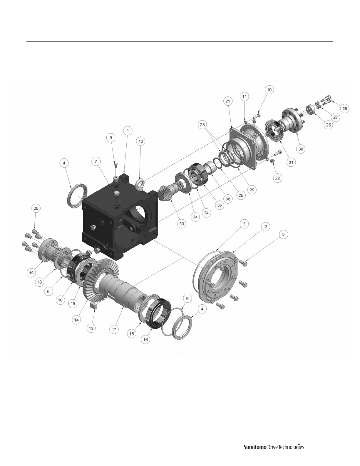
2
Cyclo®BBB
General Construction
Bevel Gear Case
Parts List
 Loading...