

Page 1
Te ch n ic a l In f or m at io n
KOUTURIGISHI-1078H
Optical Connector Termination Tool
CAK-0057-EX
Instruction Manual
2011-03-16
SUMITOMO ELECTRIC INDUSTRIES, LTD.
★The information contained herein is presented only as a guide for the applications
of our products. No responsibility is assumed by SUMITOMO ELECTRIC for any
infringements of patents or other rights of the third parties which may result from
its use. No license is granted by implication or otherwise under any patent or patent
rights of SUMITOMO ELECTRIC or others
★The information contained here may be changed without prior notice. It is therefore
advisable to contact SUMITOMO ELECTRIC before proceeding with the design of
equipment incorporating this product.
© Sumitomo Electric Industries, Ltd.
Page 2

CONTENTS
Page
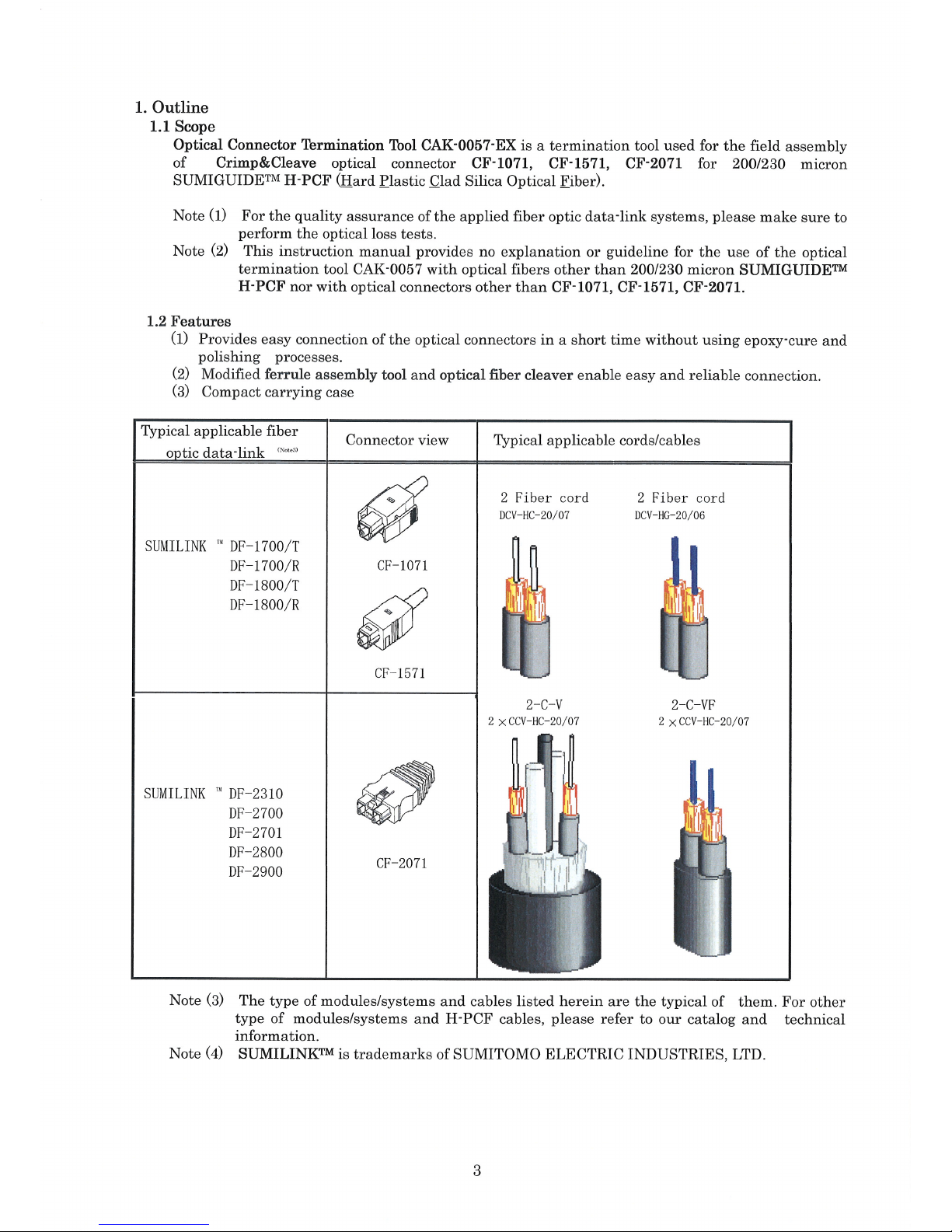
1. Outline 3
1.1 Scope 3
1.2 Features 3
2. Composition of CAK-0057-EX 4
2.1 Composition diagram of CAK-0057-EX 4
2.2 Component parts of CAK-0057-EX 4
3. Component parts of optical connector 5
3.1 Parts list of optical connector 5
3.2 Conceptual diagram for assembly of optical connector 6
4. How to use a microscope 7
4.1 Inspection of a cut face of optical fiber 7
4.2 Batteries exchange 7
5. Assembling procedure for H-PCF cables / cords 8
5.1 Preparatory work for optical fiber cable 8
5.2 Preparatory work for the optical fiber cord 9
5.3 Preparatory works for the ferrule attaching process 9
5.4 Attaching the ferrule 13
5.5 Cleaving the optical fiber 15
5.6 Inspection of the end surface of the cleaved optical fiber 16
5.7 Assembly of the optical connector CF-2071 18
5.8 Assembly of the optical connector CF-1071,CF-1571 21
6. Cable end installation 22
7. Ordering information 23
8. Trouble shooting 24
1
Page 3
2
Caution
,fingers or other parts of a body.
Be careful not to be stuck with tip of optical fiber in eyes,
It may cause lose sight or other serious injuries.
Handle the tools and connector component parts with care
Caution
not to get injured or damage them.
Don't put fingers or other parts of a body between the blades
of ferrule assembly tool JRFK-57 in use. It may cause injury.
Caution
Use tools according to this instruction manual.
Wrong usages may cause injury , damage of the tool or sub-
Attention
standard assembled connector.
To ol k it C AK - 00 57 i s de s ig ne d on ly fo r o ur a p pl ic ab le
connectors described on the page 3.
Don't use for any other products. It may damage the tool.
Attention
For the quality assurance of the applied fiber optic data-link
systems, please make sure to perform the optical loss tests
Attention
after assembling connectors.
Page 4
Page 5
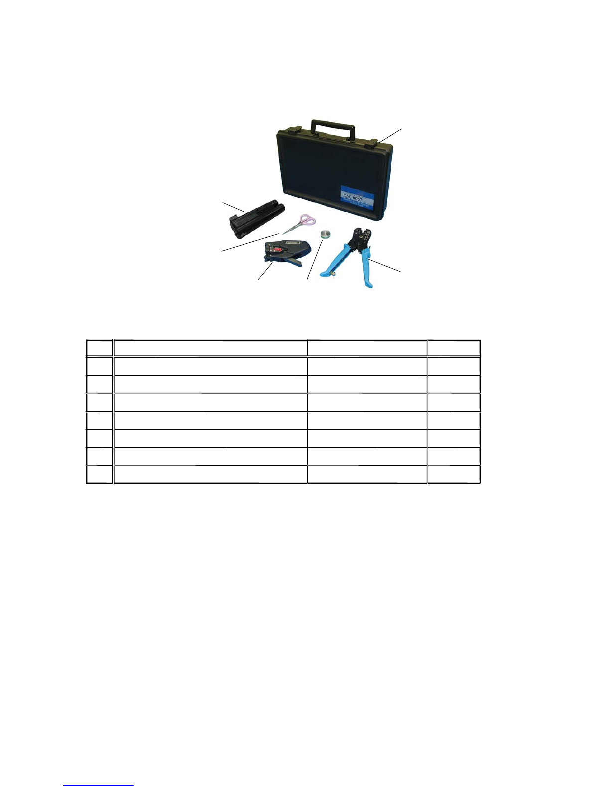
2. Composition of CAK-0057-EX
2.1 Composition diagram of CAK-0057-EX
6
5
4
3
2
1
2.2 Component parts of CAK-0057-EX
1
Optical fiber cleaver
2
Ferr
ule assembly tool
3
Microsc
ope CAT-0057B
1
CR-CF2071
5
Scissors
-
1
6
-
1
7
Instruction manuals (English) KOUTURIGISHI-1078
1
Carrying case
4
Cap remover
Prod
uct name of component
No.
1
1
JRF
K
-57
Quantity Sub code
FOCUS200-
EX
1
4
Page 6
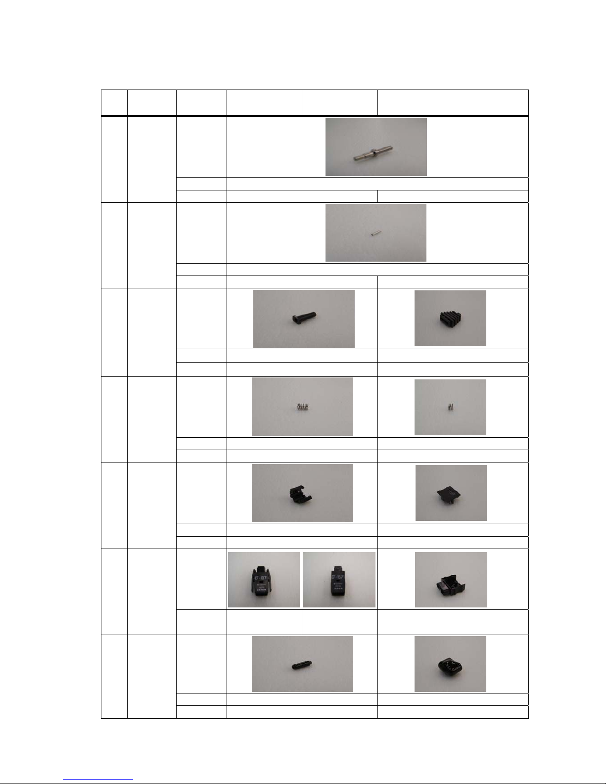
3. Component parts of optical connector CF-1071,CF-1571,CF-2071
3.1 Parts list of optical connector
No.
Product
name
Item CF-1071 CF-1571 CF-2071
Figure
Code FL-CF1071
1 Ferrule
Quantity 1 2
5
Figure
Code Collar 4511
2 Collar
Quantity 1 2
Figure
Code VJA7084 CB-CF2071
3
Cord
Bush
Quantity 1 1
Figure
Code VJM7069 SP-CF1071
4
Coil
Spring
Quantity 1 2
Figure
Code VJA7218 CP-CF2071
5
Plug
Cap
Quantity 1 1
Figure
Code VJA7219-S1 VJA7217-S1 CS-CF2071
6
Plug
Case
Quantity 1 1 1
Figure
Code VJA7115 DC-CF2071
7
Dust
Cap
Quantity 1 1
Note (1) The quantity is the requirement for a piece of the fiber optic connector.
Page 7
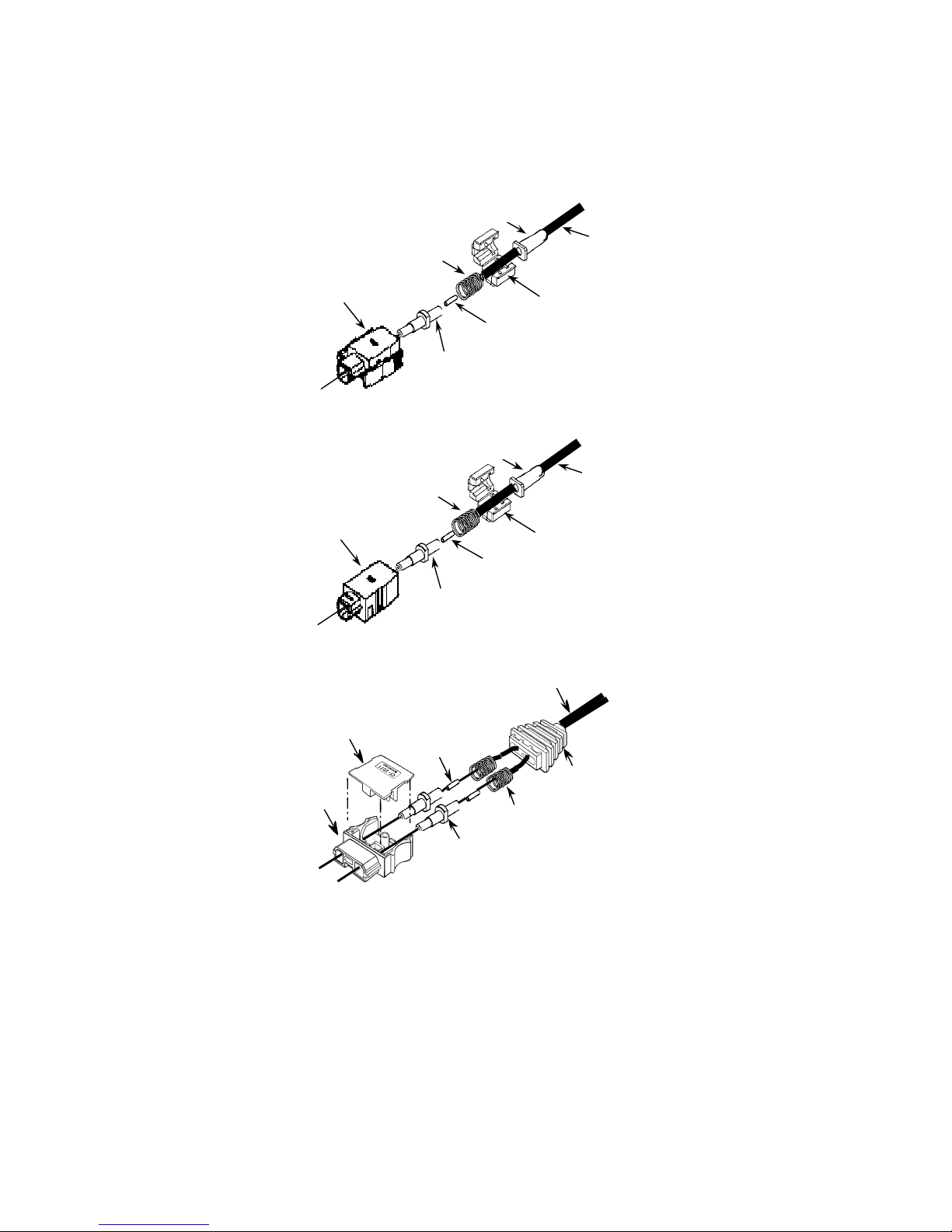
3.2 Conceptual diagram for assembly of optical connector
Plug Case
Ferrule
Collar
Coil S
p
rin
g
Plug Cap
コードブッシ
光ファ
イバコー
Cord Bush
Plug Case
Ferrule
Collar
Coil Spring
Plug Cap
光ファ
イバコー
Optical Fiber Cord
Optical Fiber Cord
Cord Bush
(1)CF-1071
(2)CF-1571
Optic
al Fiber Cord
6
Collar
Plu
g
Ca
p
Cord Bush
F
errule
Plug Case
(3)CF-2071
Coil Spring
Page 8
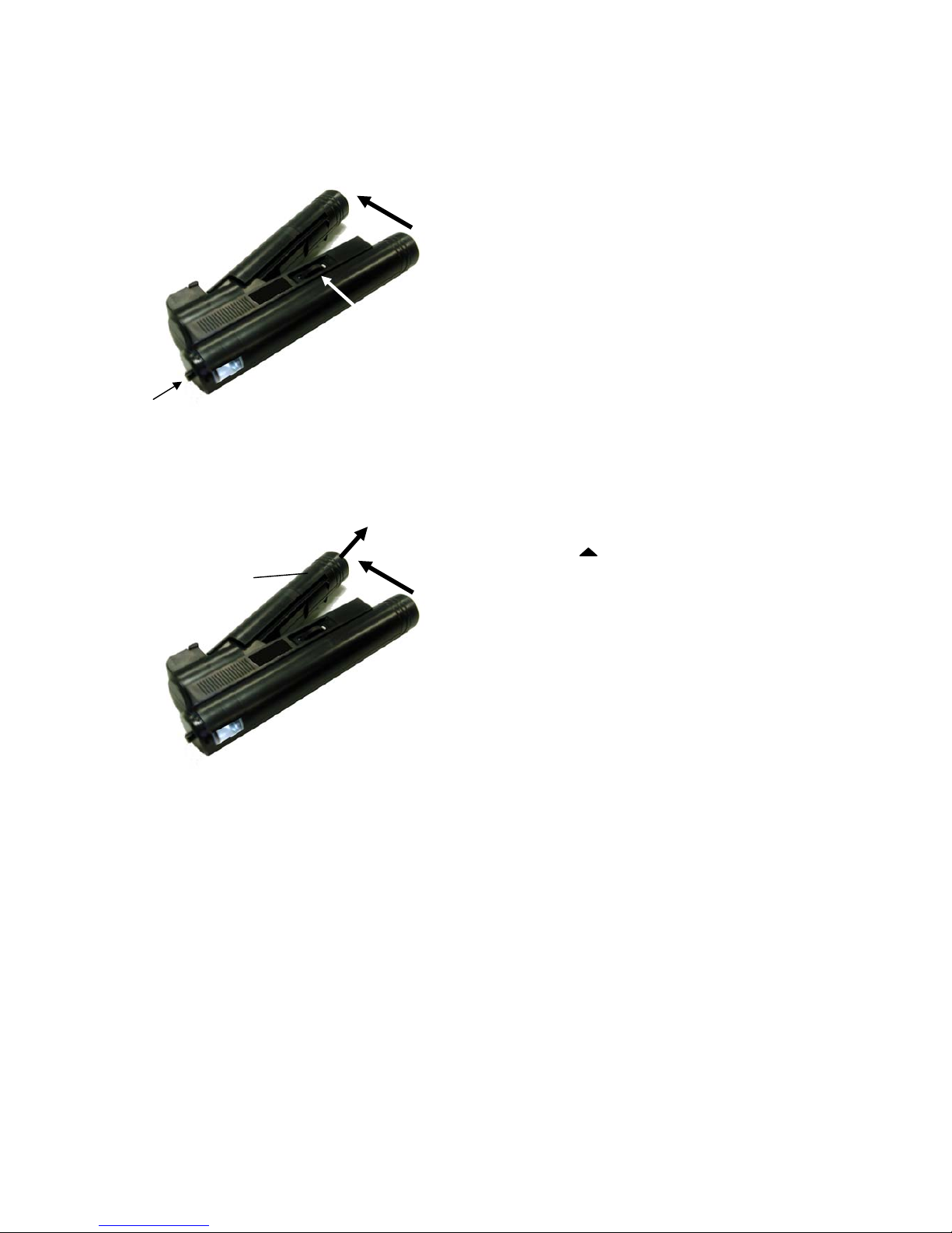
4. How to use a microscope
4.1 Inspection of a cut face of optical fiber
Open the arms, then a lamp inside turns on.
Insert the ferrule into the hole of the ferrule
adaptor ,and then the face of the cut fiber and the
ferrule can be seen by adjusting focusing dial.
Attention: When the microscope is not in use, close its
arms to prevent batteries from exhausted.
Focusing dial
Ferrule adaptor
1. open
4.2 Batteries replacement
Open the arms and slide the cover in the direction
shown by “ “, then there appears the battery
container.
Attention: When the microscope is not in use, close
its arms to prevent batteries from exhausted.
2. slide
Cover
1. open
OPEN
7
Page 9
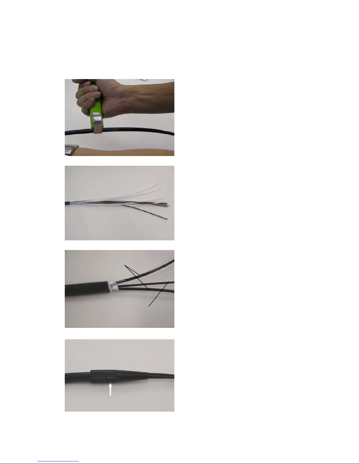
5. Assembling procedure for H-PCF cables/cords.
5.1 Preparatory work for optical fiber cables
(The work shown in this page is mentioned only for cables. In case of cords, please skip it and start
from the next page.)
8
Fig.3
(1) Remove the sheath by using your own
knife. (Fig.3)
Remove length ----- 200mm (Reference
value)
Fig.4
(2)
Cut off the hold tape, the filler and the
filler cords at the end of the sheath with
the scissors to expose the optical fiber
cords and the central strength member .
(Fig. 4 to 5)
Strength member
Optical fiber cord
Fig.5
Protective boot
Fig.6
(3) Insert the optical fiber cords and the
tension member into the protective boot
and cover the end of the sheath with the
protective boot. (Fig. 6)
Page 10
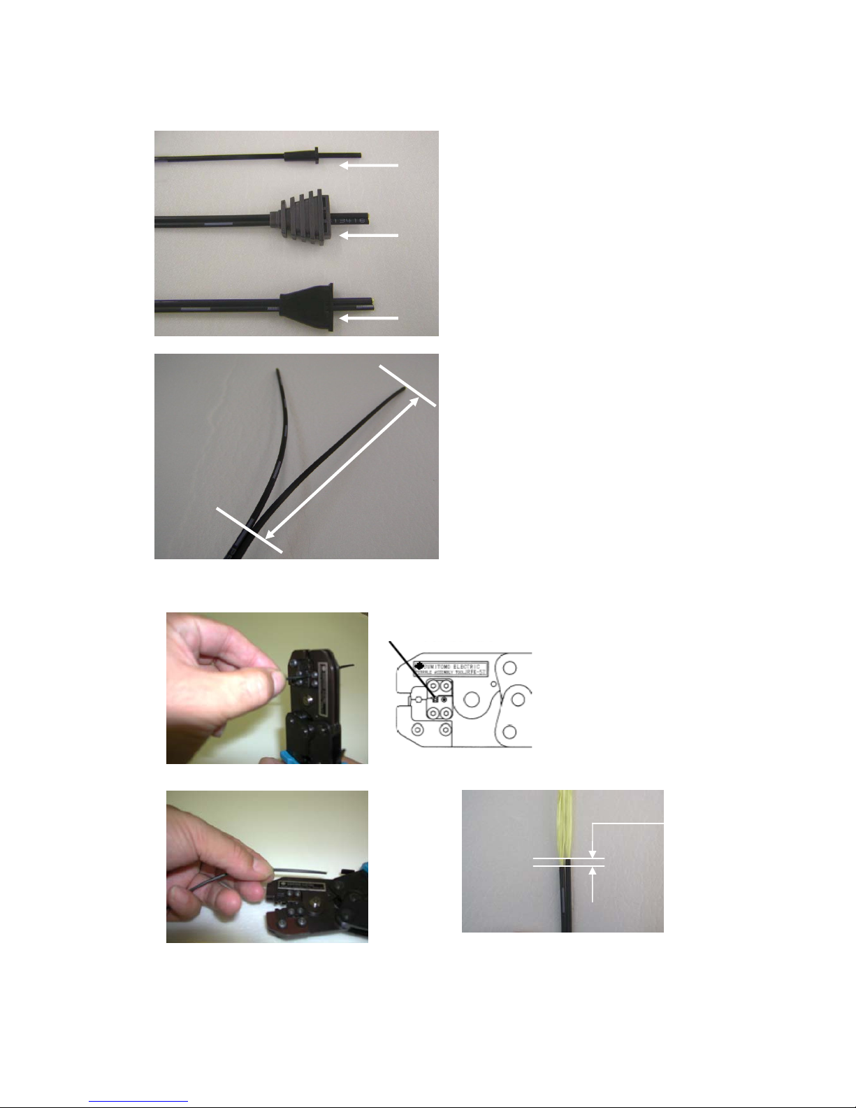
5.2 Preparatory work for the optical fiber cord.
Fig.7
Fig.8
130±20mm
CF-257
1
CF-2071
CF-1071・CF-1571
(1) Ins
ert the optical fiber cord from the
bottom(smaller) mouth of the cord bush.
(Fig.7)
(2) Insert the gap at the end of the connection
part of the optical fiber cord, and then by
tearing the optical fiber cord, separate it into
simple cord each. ( Only for the duplex cord.)
Separation length ----- 130
+
-
20 mm (Fig.8)
5.
3. Preparatory work for the ferrule attaching process
Fig.10
(1) I
nsert the cord into the outer
jacket remover of the ferrule
assembly tool from its front
face (label face) , and then
grasp the handle and pull
the cord back straight. In this
way, the outer jacket (black)
of the optical fiber is removed.
(Fig.9 ,10)
Remove length ----- 35 mm
Fig.9
Outer
j
acket remover
Max 1mm
Note:T
he difference in jacket lengths
should be no more than 1mm.
(Fig.11) Otherwise the optical
fiber may bend when the connector
is assembled.
(Fig
. 11)
Fig.12
Note:F
or remove length please refer to
the label that has 35mm width.
(Fig. 12)
9
Page 11
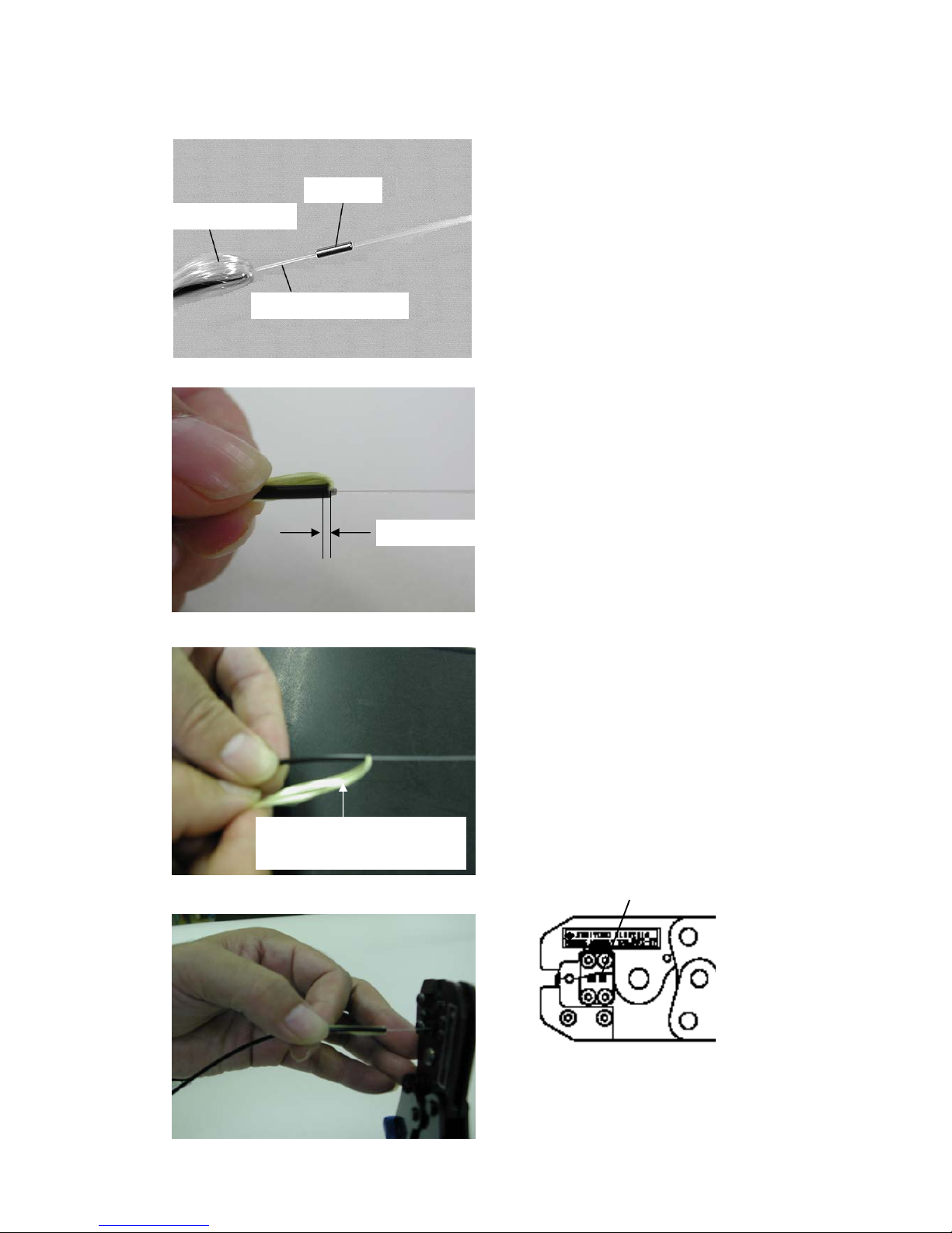
10
補強材
最
大1mm
心線
Protective coating
Strength member
Collar
Max.1mm
撚り合わせる
Fold and strand the
strength member tightly
(Fig. 15)
(Fig. 13)
(Fig. 14)
(2) Fold bac
k the strength member yarn
at about two strands and then insert
the optical fiber into the collar . (Fig.
13)
(3) Ins
ert the collar into the cord jacket.
Note: Please make the collar projected from
the cord jacket by no more than 1mm.
(Fig.14)
(4) Keep the strength member folded and
strand it tightly. (Fig.15)
(5) P
ut the optical fiber in protective coating
remover through guide hole from front
face (label face). (Fig.16 ,17)
(Fig. 17
)
Protective coating remover
(gu
ide hole)
Note:
Be careful not to nip the strengt h
member between the blade of the
remover, or the blades will be
damaged.
(Fig. 16
)
Page 12
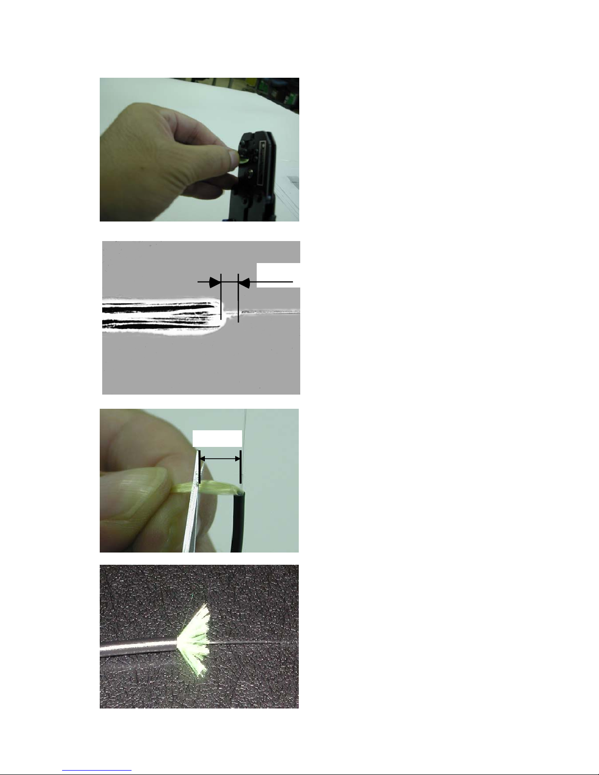
(6) Grasp the handle and pull the fiber back
straight. (Fig.18)
(Fig.18)
(Fig.1
9)
0-5
mm
Note: T
he remaining length of the protective
coating should be less than 5mm. (Fig.19)
(7) Adjust the length of the strength member
to 5 to 6mm with scissors. (Fig.20)
5 to 6mm
(Fig.2
0)
Note: Make sure to
leave the strength
member 5 to 6mm. This is necessary
to get the pullout strength between
the optical fiber cord and the ferrule.
(Fig.21)
(Fig.2
1)
11
Page 13
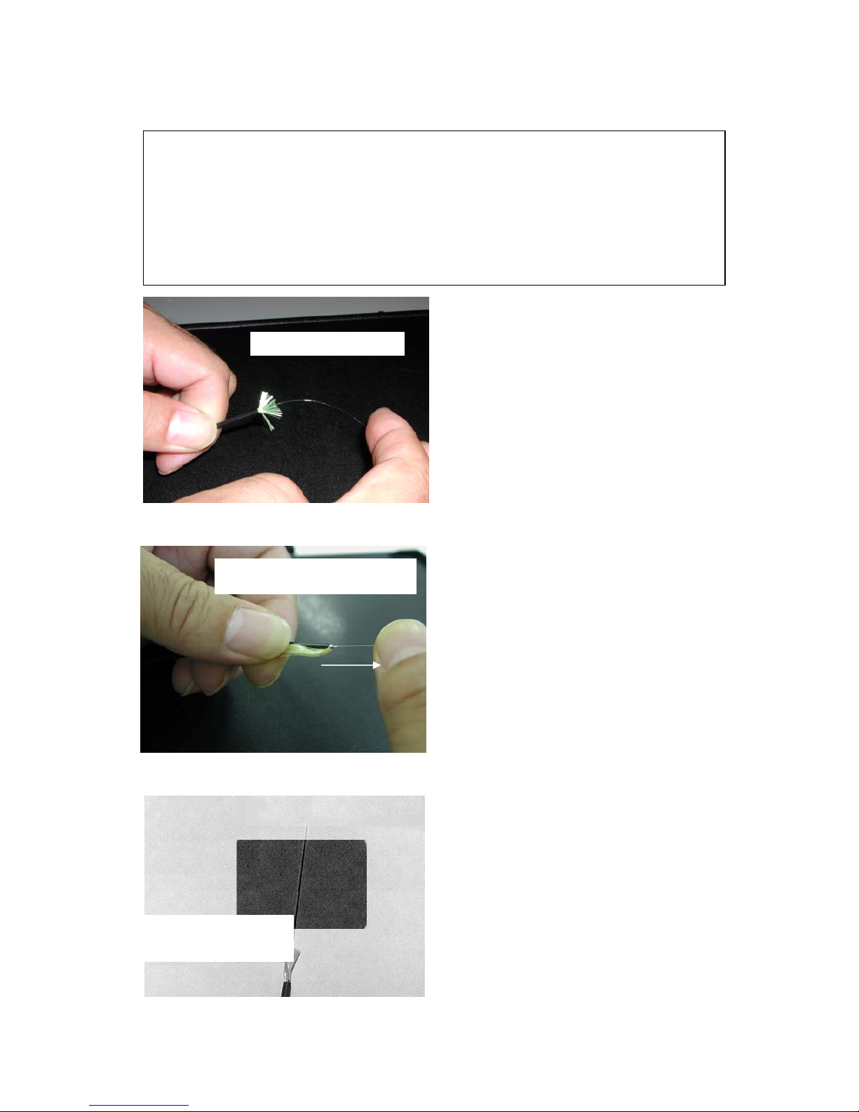
Caution
12
When the blades of the protect coating remover are broken or the procedure is out
of accord with this manual, during the stripping of the protective coating, it may happen
that the plastic cladding of the optical fiber is damaged (surface of the cladding is whitened
or becomes glittering). In this case, the optical fiber may be broken at the point of the
damage in the succeeding assembling process or in the connector under use, because the
cladding of H-PCF is a vital part to insure its high-strength and high-reliability by
protecting the silica core. So please do not forget to perform the following proof test before
proceeding the next step in order to make sure that there are no damage on cladding
whether the the surface of the cladding is whitened or not.
Bend the optical fiber
(Important)
(8) Hold the optical fiber cord (black,
2.2mm dia.) by a hand and tip the
bare optical fiber (core & cladding) 3
to 4 times gently with a finger of
another hand so that the fiber bend
+-120 degrees. And squeeze the
surface of the whole length of the
bare optical fiber about ten times
from the protective coating end to the
fiber end.
(Fig.22)
Squeeze through the fingers
If th
e cladding is damaged, the fiber
is broken down through these
screening processes. (Fig.22 to 23)
Finally observe the bare optical fiber
against a black background so that
the damage of the cladding can be
seen white like. (Fig.24)
Note: Be careful not to damage the
cladding by scratching the fiber
surface with nails.
(Fig.2
3)
Note: Eye glasses or Protecting goggle is
recommended to save your eyes
from particles of the broken fiber.
Note: Particles of the broken fiber should
be collected by adhesive tape or
other method to avoid that they
harm human bodies.
Observe against
black background
(Fig.2
4)
Page 14
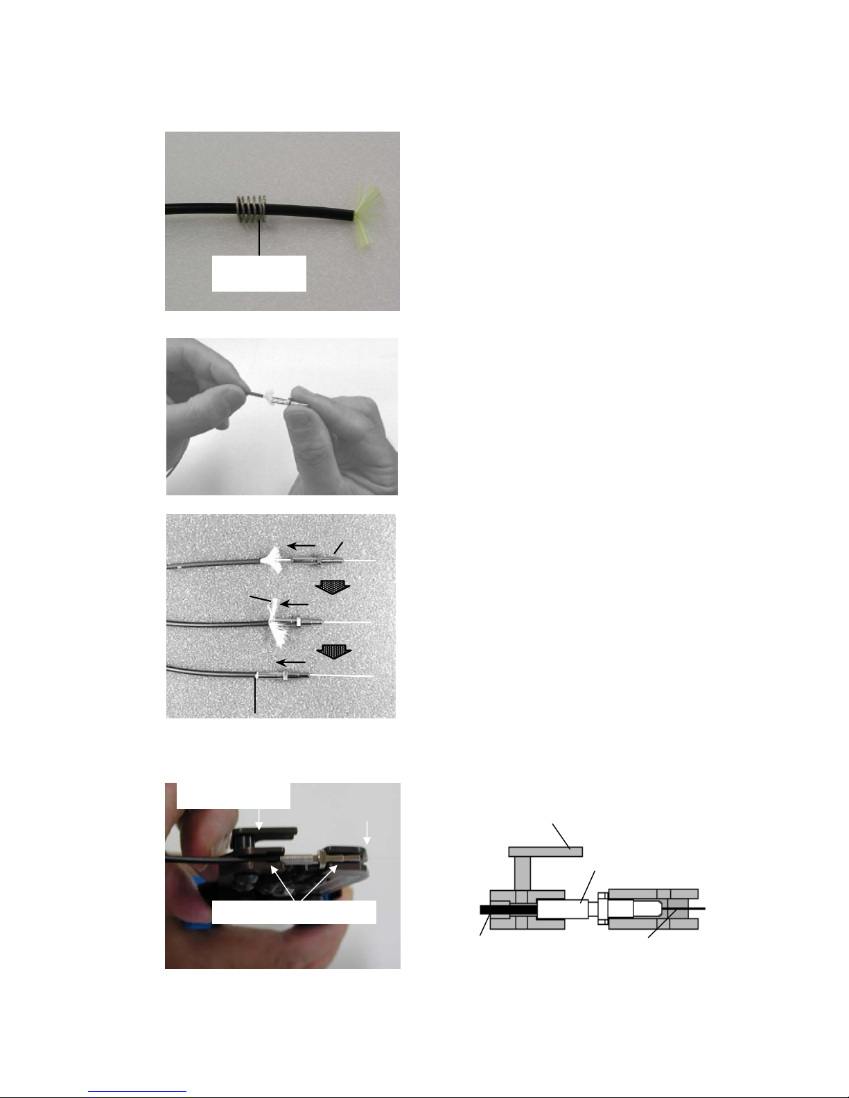
5.4 Attaching the ferrule
(1) F
ix the coil spring onto the optical fiber
cord. (Fig.25)
Coil spring
(Fig.2
5)
Note:
When assembling duplex type
connectors, perform the operations from
this step to "5.5 cleaving of the optical
fiber" separately for each core of the
optical fiber.
(2) Ins
ert the optical fiber into the ferrule.
(Fig.27)
(Fig.26)
Note: Make sure to insert the optical fiber
cord into the ferrule exactly until the
folded strength member projects no
more than 2mm from the bottom of
the ferrule.(Fig.27)
(Fig.2
7)
The tip of the strength
member should be seen
Strength member should
Be folded back
Ferrule
(3) S
et the flange of the ferrule inserted the
optical fiber on press-in blade.
Note the set direction. (Fiber cord
should be to ferrule guide.)
(Fig.28 ,29)
Flange
Ferrule guide
Ferrule press-in blade
Ferrulie guide
Optical fiber
Ferrule
(Fig.2
9)
(Fig.2
8)
13
Page 15
14
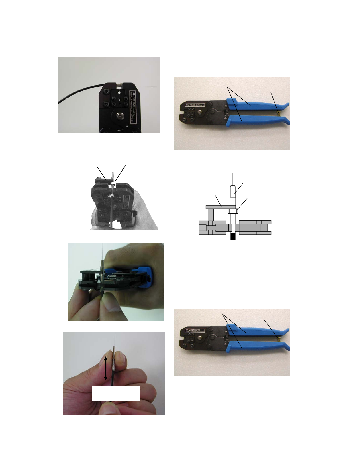
(4) Grasp the handle till it goes no more touching
on the limit screw. (Fig.30,31)
This makes the ferrule pressed axially and
shortened, and the optical fiber is held inside.
handle
limit screw
(Fig.30)
(Fig.31)
(5) S
et the ferrule onto ferrule guide putting the
flange of the ferrule on the ferrule guide from
inside. (Fig.32,33)
Flange
Ferrule guide
(Fig.3
3)
Ferrule g
uide
Flange
Ferrule
(Fig.3
2)
(Fig.3
4)
handle
(6) Gr
asp the handle till it goes no more touching
on the limit screw, with pushing the optical
fiber cord slightly toward the ferrule in order
not to get out the cord from the ferrule.
(Fig.34,35)
This makes the outer jacket of the cord and
the strength member grasped between the
collar and the ferrule.
limit screw
Lightly stretch
(Fig.3
6)
(Fig.3
5)
(7) Lightly stretch the ferrule from the optical
fiber cord by hands to confirm that the
optical fiber cord is tightly fixed onto the
ferrule. (Fig.36)
Page 16
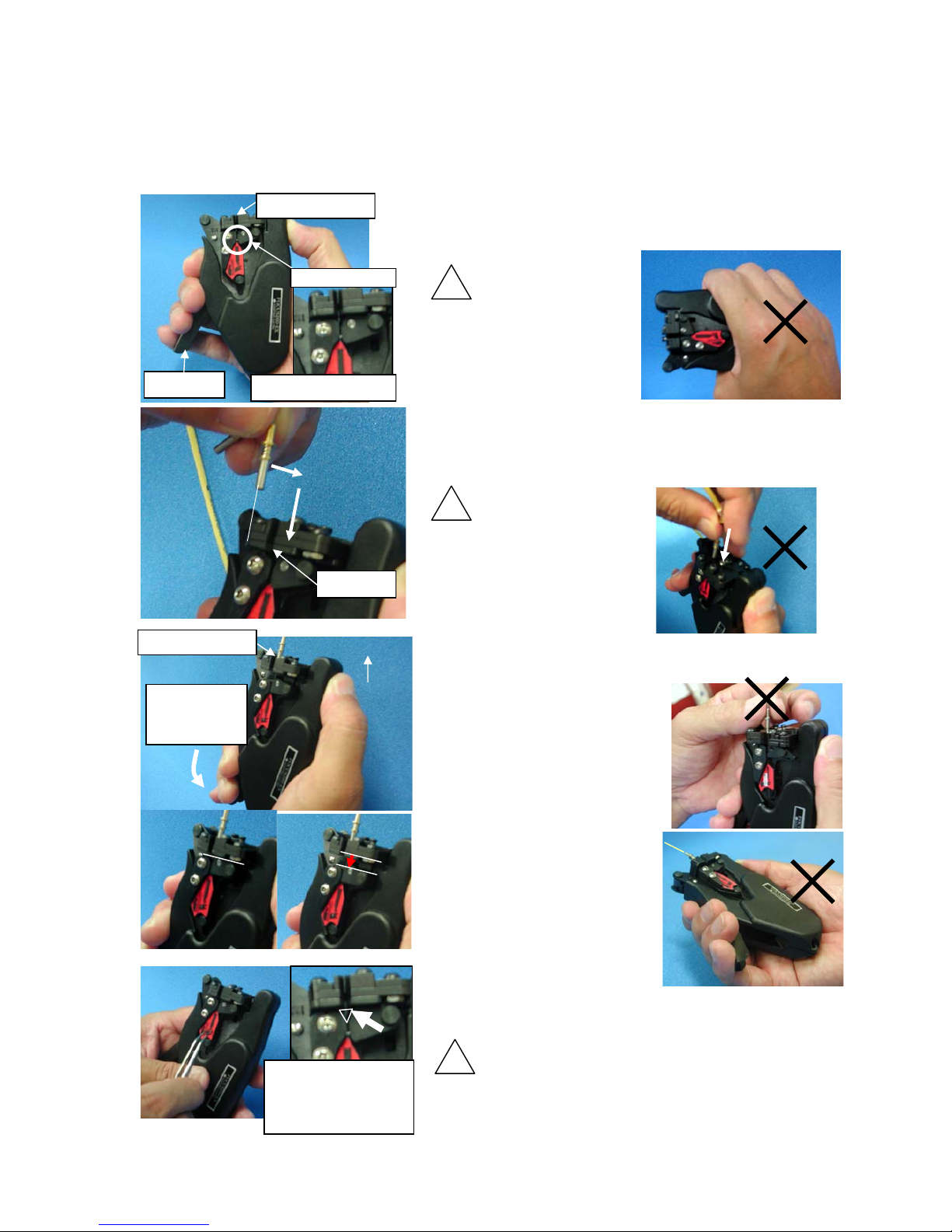
5.5 Cut the fibers (at the face of the ferrules)
Please see the instruction manual for respective connector and the tool kit except for the procedure
shown bellow.
15
(1) Hold the cleaver with your right hand as shown in the
left photo.
(2) Make sure that there are no fiber chips or other waste
remained on fiber chuck.
Don’t hold the cleaver covering
fiber chuck with the hand as
shown in the right photo.
Fiber chip at the fiber chuck may
hurt the hand.
(3) Let the optical fiber coming out of the ferrule through
the front slit, then insert the ferrule into the hole for
ferrule. Then make sure that the ferrule is put in
deep enough for the front face of it to be on the blade.
Note : Don’t let the optical fiber
through the hole for ferrule.
It may break the fiber.
(4) Direct the hole for ferrule upward, and slowly, press
up the lever to the end, then the optical fiber will be
cut properly.
*Don’t touch the ferrule when
pressing the lever. It can cause poor
cleave quality.
*Don’t press up the lever fast. It
can cause poor cleave quality.
*The lever should be pressed up to
the end. When the optical fiber is
cut, the fiber chuck is slide back.
*Hole for ferrule should face
upward when pressing the lever.
Otherwise, the optical fiber may be
cut at a little out of the face of
ferrule.
(5) Release the lever, and take out the chip of optical
fiber from fiber chuck with tweezers.
Chips or particles of optical fibers can hurt human body. Be careful
not to be stuck.
Hole for ferrule
Fiber chuck
lever
No remained fiber
Bad example
! Attention
Front slit
(2)
(1)
! Attention
Bad example
Hole for ferrule
Upward
Slowly, press
up the lever
to the end.
Bad
example
Close to
each other
Slide
back
No
t finished
Finished
Bad example
If the fiber chip is
short, insert tweezers
from this small slit to
pick it up
! Attention
Page 17
(Important)
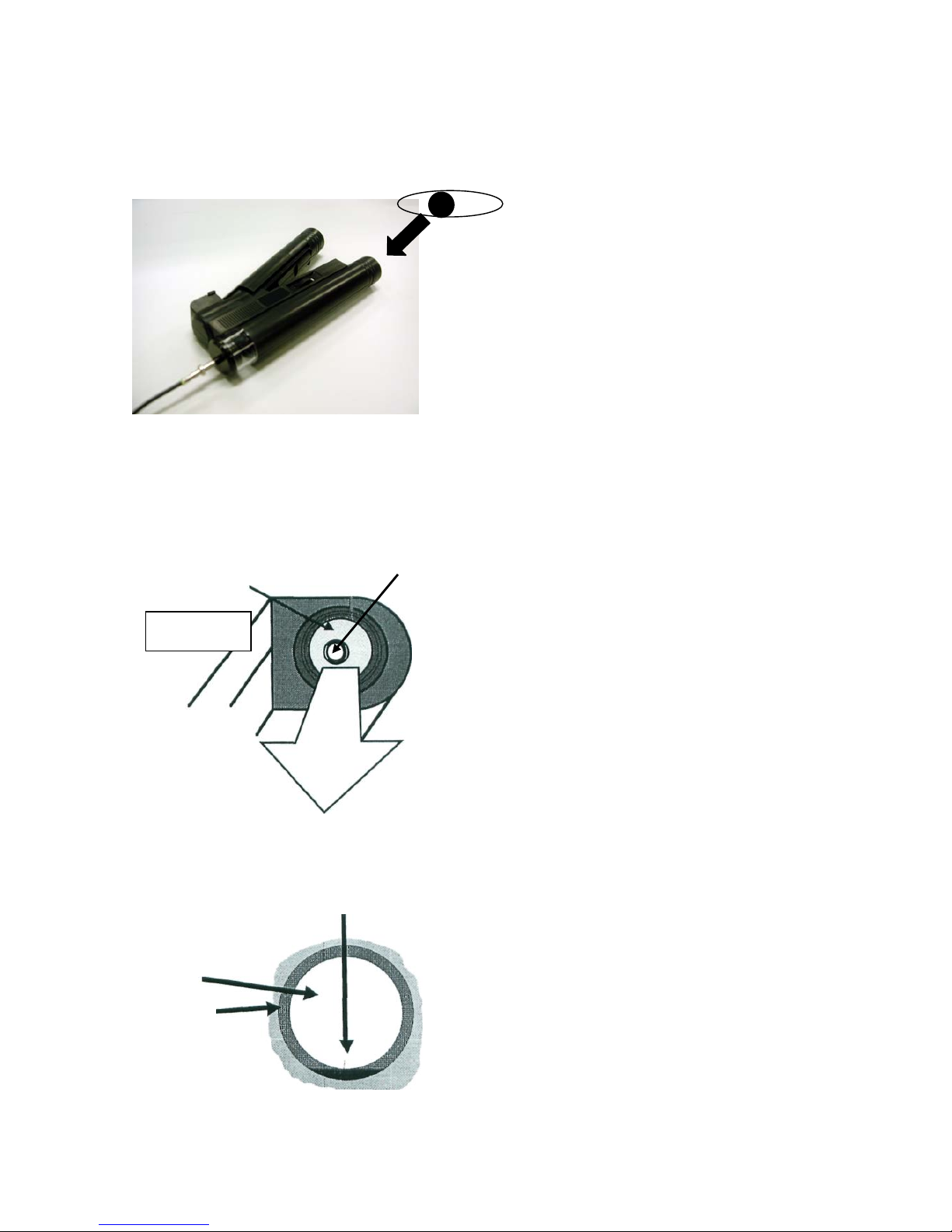
5.6 Inspection of the end surface of the cleaved optical fiber.
Inspect the finished end surface of the
optical fiber with using the microscope
CAT-0057B. (Fig.42)
(Pleas see page 7 for detail.)
* Make sure to perform also the optical
power test by using the optical power
tester.
* Inspect the face with revolving the
ferrule.
* Inspect the face with lighting the another
end of the optical fiber.
* The faces of the optical fibers, together
with those of the ferrules, will be seen
with a microscope. compare them with
examples shown next page. If they
correspond to any of sub-standard
samples, retry from the first stop.
(Fig.42)
Cladding
Face of the cleaved
optica
l fiber
ゴミ
(Fig.43)
Microscope
Face of th
e ferrule
(Satisfactory sample)
The face if the core is smooth and the
length of the crack is less than 1/10 of the
core diameter.
(Fig.44)
Crack
(Fig.44)
T
he faces of the optical fibers, together
with those of the ferrules, will be seen
with a microscope.
(Fig.43)
Core
16
Page 18
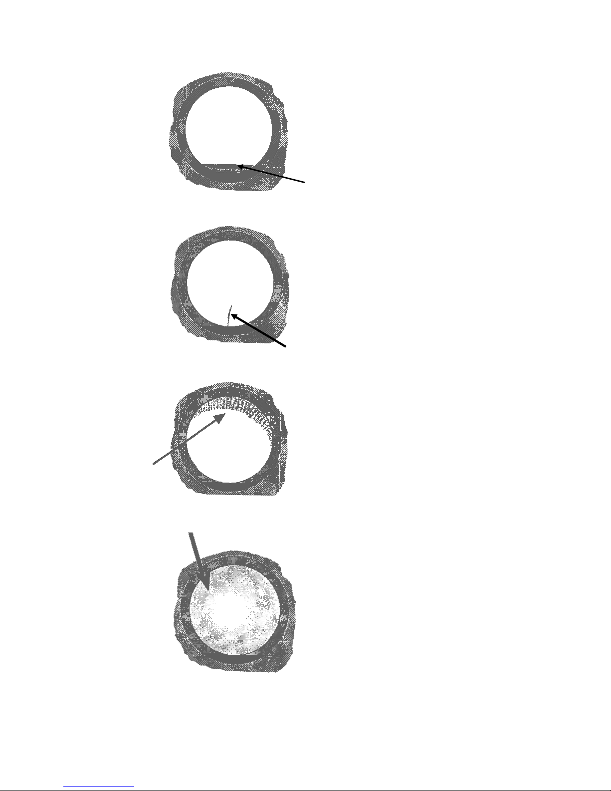
(Sub-standard sample)
The length of cutting flaw is more
than 1/8 of the core diameter.
(Fig.45)
(Fig.45)
Cutting flaw
(Fig.4
6)
(Sub-stan
dard sample)
Cutting face isn't right angled to the axis
of the fiber.
(Fig.48)
(Sub-standard sample)
The length of the crack is more than 1/10
of the core diameter.
(Fig.46)
(Sub-standard sample)
Hackle is observed on the face.
Crack
(Fig.47)
Hackle
17
Dark image
(Fig.4
7)
(Fig.48)
NOTE: When the quality of the faces of optical fiber get poor frequently, please move the blade
to shift the cutting potion reference in page 25.
Page 19
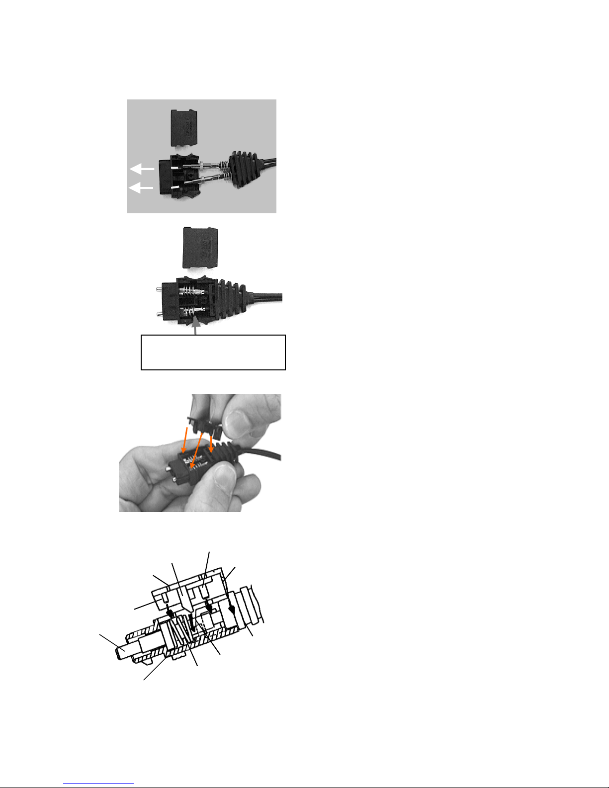
5.7 Assembly of the optical connector CF-2071
(See 5.8 for CF-1071 and CF-1571)
(1) Insert the both ferrules into holes on the
plug case from inside, and fix the cord bush
onto the groove on the plug case. (Fig.49)
18
Plug cap
Cord bush stopper
Center guide pin
Side guide pin
Coil spring stopper
Cord bush
Coil spring
Guide groove taper
(2) Put th
e coil springs within the hollow inside the
plug case. (Fig.50)
Make sure that the each coil spring doesn't get on
the rim of the hollow.
(3) Put the plug cap into the plug case taking care
that the ferrules,the coil springs and the cord
bush don't get out of their places.(See below
and Fig51,52)
・This procedure will be easier when the plug case
is held slightly inclined as shown in Fig.51,52.
・Plug cap should be pushed in being kept parallel
to the plug case.(Fig.52)
・The spring stopper on the plug cap should go
along the taper part of the guide groove inside
the plug case, so that the stopper will hold the
end of the coil spring correctly.(Fig.52)
・The cord bush stopper on the plug cap should go
into the hole on the cord bush.(Fig.52)
・A center guide pin and two side guide pins on
the plug cap should go into respective holes on
the plug case.(Fig.52)
(Fig.50)
(Fig.49)
Make sure that the each coil
spring doesn't get on the rim of
the hollow.
(Fig.5
1)
Ferrule
Plug case
(Fig.52)
Page 20
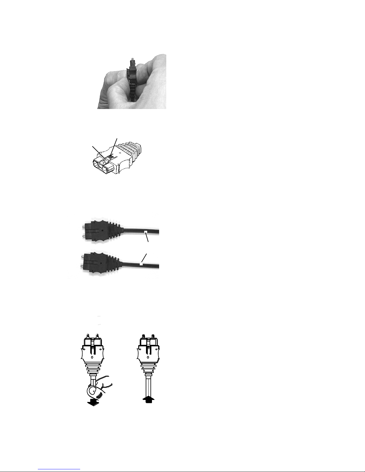
(4) Push in the plug cap completely. (Fig.53)
Attent
ion:
-Don't push on a latch arm especially a lock
release button. Stresses given on the latch arm
may break it and cause latch lock failure. (Fig.54)
(Fig.5
3)
Lock release button
Latch arm
Attent
ion:
-Incorrect placement of coil springs or ferrules
may cause interference against the plug cap.
When the plug cap isn't put in completely, remove
the plug cap and retry with new plug case and
plug cap.(They may be damaged with put-in and
remove procedure.)
(Fig.5
4)
Attent
ion:
White marking arranged
symmetrical position
-Set th
e ferrules so that the white mark on the
optical fiber cord connected to one connector may
be symmetrical to that on the optical fiber cord
connected to another. (Fig.55)
(Pay attention to the positions of the
light-emission and light reception sides of the
two optical connectors.)
(Fig.55)
19
When pull the cord,
the ferrules are also
moved back .
When release,
ferrules return to
the original position.
(5) T
o examine the connector assembled
correctly , pull the optical fiber cord lightly
(<20N) on and off holding the plug case ,
and see if the ferrules move to it. (Fig.56)
If not, there may be something wrong
inside.
P
lease disassemble and check up.
(Fig.56)
Page 21
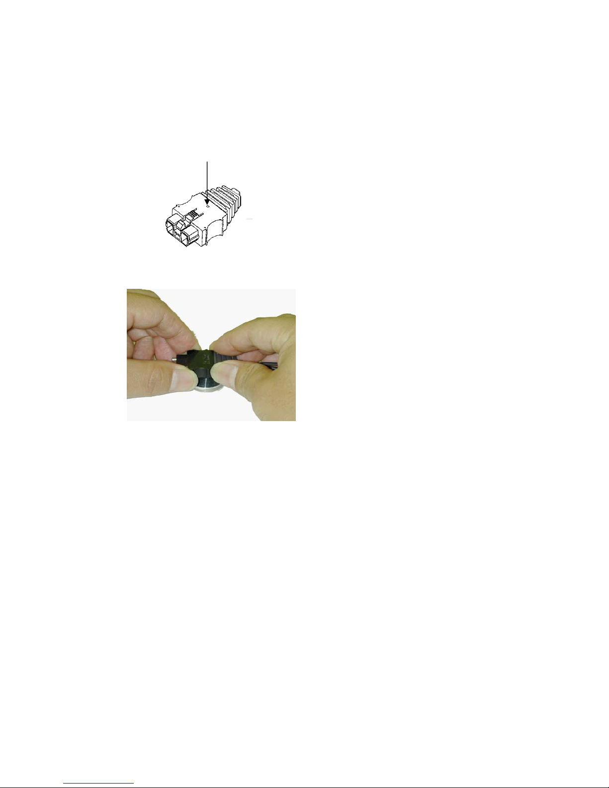
(6) The
plug cap put in the plug case may be
removed by pushing out the center guide pin on
the plug cap through the center hole of the plug
case (Fig.57) by the cap remover. Put the cap
remover on an appropriate table setting its
center pin to the center hole on the plug case,
and then hold the sides of plug case by both
hands and push it down strongly (Fig.58).
Attention:
・Once a plug cap is removed, the plug cap and the
plug case should be replaced with new ones.(They
may be damaged with put-in and remove
procedure.)
・Remove operations should be done with care to
prevent human body from getting hurt. Especially,
if it is done with holding the cap remover by your
hand, you may be injured by the unexpected
situations, such as the pin slipped out from the cap
remover. So this operations must be done with
putting the cap remover on an appropriate table.
・Remove operations should be done with care not to
damage the optical fibers and coil springs.
Center hole
(Fig.57)
(Fig.58)
20
Page 22
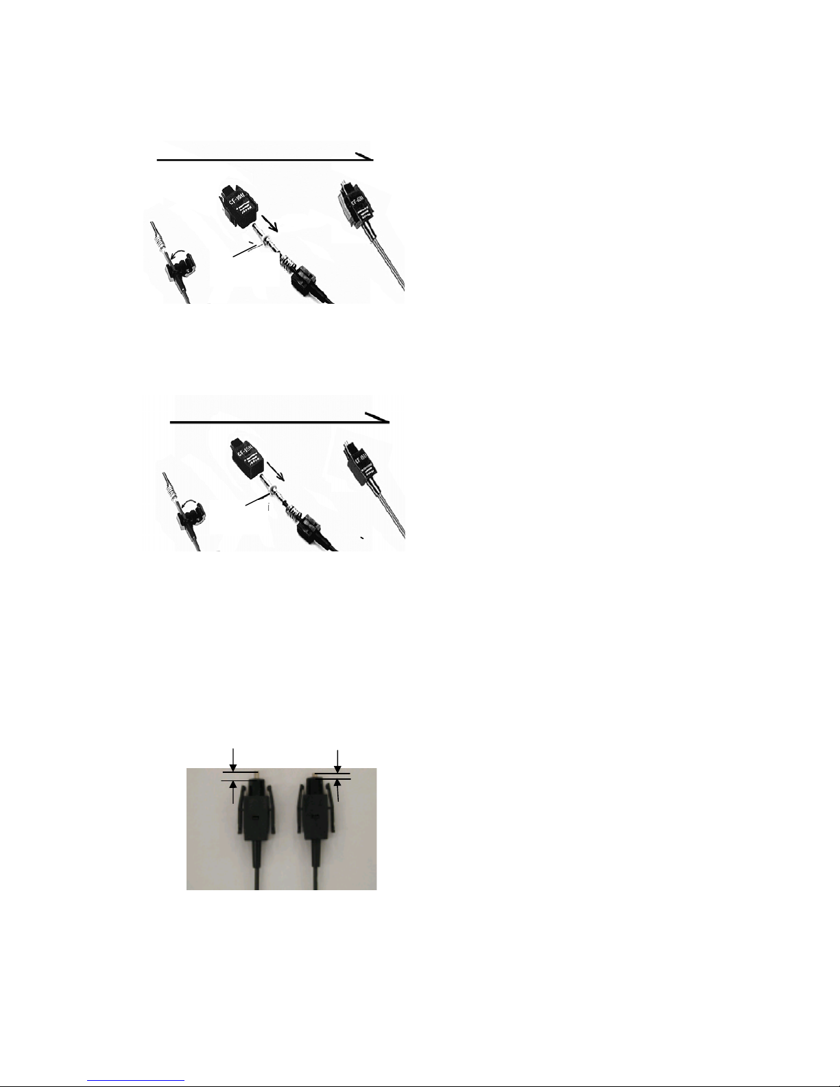
5.8 Assembly of the optical connector CF-1071,CF-1571
Flat
surface
③
② ①
(1) F
ix the plug cap onto the cord bush.
(shown as ① in Fig.59 and Fig.60)
(2) Assembly of the plug case.
(shown as ② in Fig.59 and Fig.60)
Note: The flange of the ferrule has two flat
surfaces to prevent the ferrule rotation.
When assembling the single fiber type optical
connectors (CF-1071&CF-1571), insert the
ferrule into the plug case so that the flat
surfaces of the ferrule contact both the right
and left sides of the ferrule
insertion hole of the plug case. If not, the
ferrule doesn`t go out of the plug case enough
and it cause coupling loss increase.
(Fig.61)
(3) To e xa mine t he co nn ec to r a ss em bl ed
correctly , pull the optical fiber cord lightly
( <20N) on and off holding the plug case ,
and see if the ferrules move to it. (Fig.56)
If not, there may be something wrong
inside. Please disassemble and check up.
Note: Disassembling should be done with care
to prevent human body from getting hurt
.
Note: Disassembling should be done with care
not to damage the optical fibers and coil
springs.
CF-1071(Fig.59)
Flat
surface
③
② ①
CF-1571(Fi
g
.60)
×
(Bad)
○
(Good)
3mm
1mm
(Fi
g
.61)
21
Note: Onc
e a plug cap is removed, the plug cap
and the plug case should be replaced with new
ones.(They may be damaged with put-in and
remove procedure.)
Page 23
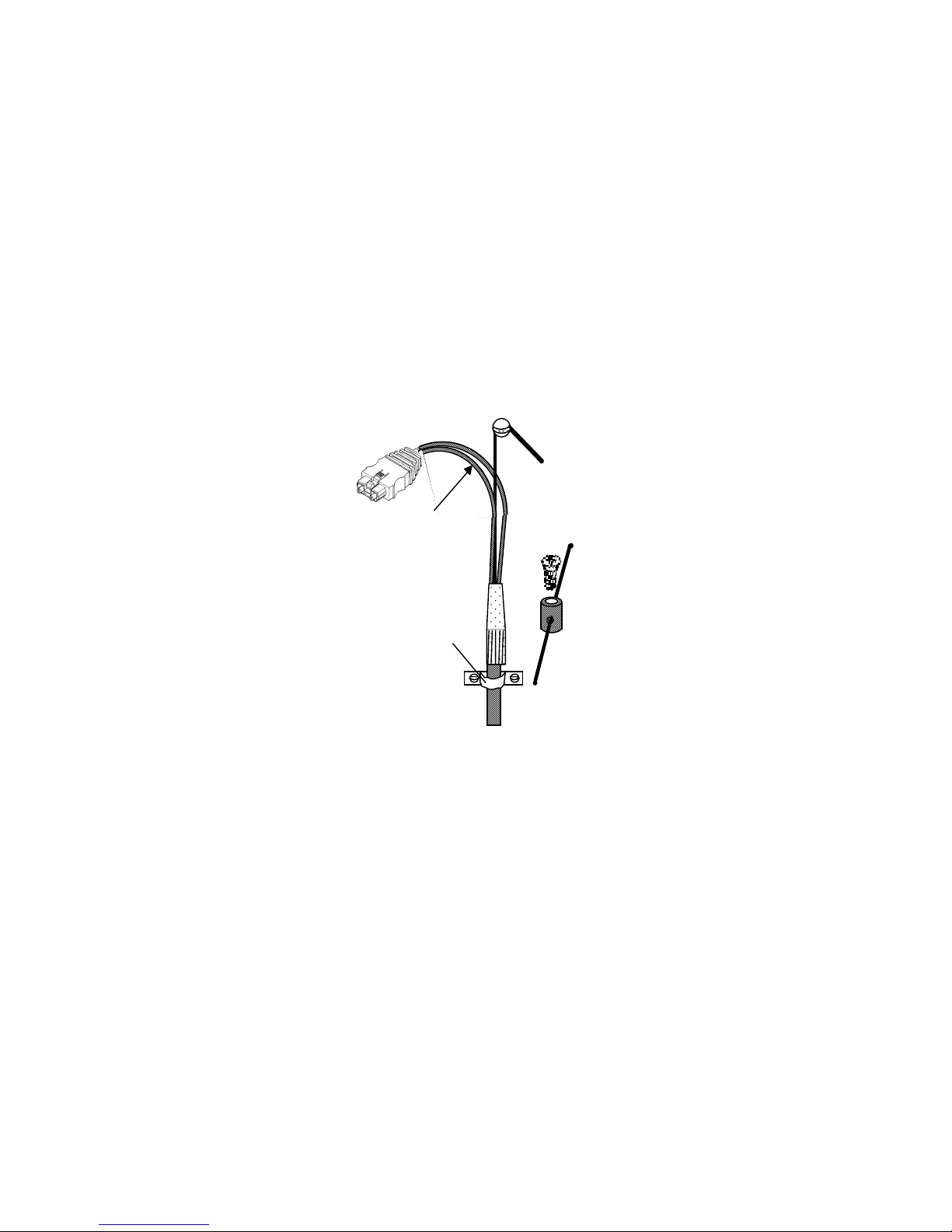
6. Cable end installation
(1) Fix the cable holding back the central tension member so that the optical
fiber cords are not stretched.
(2) Use cable holder or so for the cable not to sway.
(Be careful not to press the cable and fiber cords with the holder.)
(3) Keep minimum radius bend of both cables and optical fiber cords.
Hold back the central tension member.
22
A
nother example to hold back the
tension member
Use cable holder or so.
Keep minimum radius bend.
(Fig.62)
Page 24
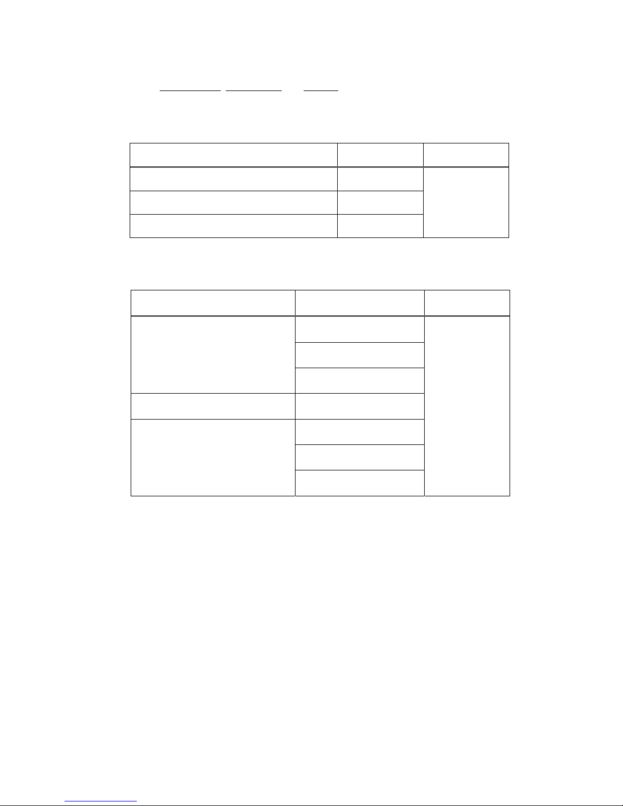
7. Ordering information
Please specify product name
, product code and number of products required.
7.1 Optical connector termination tool kit
23
7.2 Optic
al connector
Product name Product code Sales unit (s
et)
Optical Connector Termination Tool Kit CAK-0057-EX
Optical Fiber Cleaver FOCUS200-EX
Ferrule Assembly Tool JRFK-57
1
Product name Product code Sales unit (set)
CF-1071
CF-1571
Optical Connector
CF-2071
Ferrule
(Note)
FL-CF1071Plus
S-201
S-202
Protective Sleeve
S-204
50
Note: A set of "FL-CF1071Plus" contains a ferrule "FL-CF10
71" and a collar
"4511"
Page 25

24
8. Trouble shooting
Trouble Typical causes and treatments
Reference
(1)
It is difficult to insert the
collar into the outer jacket
properly.
* The strength member is put aside.
[Please fold back the strength member at about two
strands.]
5.3 (2)
(2)
When striping off the
protective coating
(semitransparent),the
optical fiber is pulled out
from the outer jacket.
* If the length of fiber optic cord is short, please
wind the fiber optic cord twice or three times
around your fingers when you strip off the
protective coating.
5.3 (6)
(3)
A
fter the stripping of the
protective coating, the fiber
is easily broken by the
bending or squeezing test.
Or, after stripping the
protective coating, white
powder-like resin is observed
on the surface of the
cladding.
* A part of the strength member yarn is crimped by
guides or blades of the protective coating remover
of the ferrule assembly tool.
* The blade of the protective coating remover of the
ferrule assembly tool is damaged by the
improper crimping of the strength member yarn
or silica core.
[Be careful not to grip the strength member yarn
with blades of the ferrule assembly tool.]
5.3 (6)
(4)
It is difficult to insert the
optical fiber cord into the
ferrule.
* The strength member is put aside.
* The protective coating (semitransparent) is not
properly removed from the end of the jacket
(black).
[Maximum remaining length:5mm]
* Separation of the duplex cord into 2 simplex
cords is not symmetric
5.4 (2)
5.3 (6)
5.3 (1)
(5)
At the stretching test
between ferrule and cord,
the cord is pulled out from
the ferrule.
* The length of the remained strength member
yarn is too short.
[Remaining length: 5 to 6 mm]
* A collar is not inserted into the jacket.
[Please do not forget to insert the collar.]
* The ferrule is not on the correct position
when it is cramped.
* The fiber cord is pulled out from the ferrule
when cramping the ferrule.
[Please push the cord slightly when cramping the
ferrule.]
5.3 (7)
5.3 (2)
5.3 (5)
5.4 (6)
(6)
Fiber isn't cleaved by pulling
the trigger or cleaved fiber
surface is not good.
* There remain fiber chips or other wastes on fiber
chuck of the cleaver.
* The ferrule isn't put deeply enough into the hole
of the cleaver.
* The fiber isn't held properly in the ferrule.
[Please check the ferrule press-in procedure. ]
* The blade of the cleaver is damaged.
5.5 (2)
5.4 (3),(4)
(7)
(Only for single fiber type
connectors) Fiber output
power is not satisfactory.
* The ferrule may not be set correctly.
5.8 (2)
Page 26
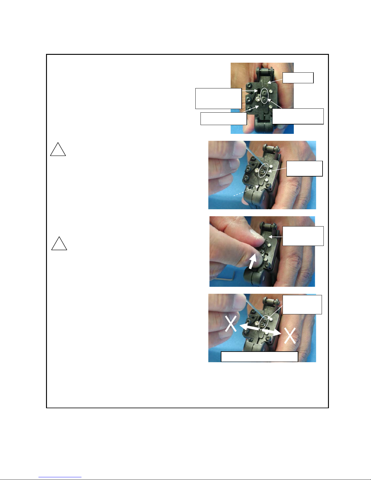
(8) Maintenance of fiber cleaver FOCU200-EX
In the case the quality of the faces of optical fiber
get poor frequently, please move the blade to shift
the cutting portion by following procedure.
* The estimated life for cutting at the one portion
of blade is about 300 cuttings.
(1) With a hex wrench (size 1.5mm), screw down
the two hexagon bolts on the blade positioning
plate to allow it move. (Fig.64)
*Don’t screw down the hexagon bolts more than 5 turns.
It can cause the cleaver trouble.
*Don’t screw down any other hexagon bolts other than
size1.5mm. It can cause the cleaver trouble.
(2) Hold the blade positioning plate and slide it to
the direction of an arrow just one division of
scale at a time. (Fig.65)
(3) Screw up the two hexagon bolts on the blade
positioning plate, avoiding pushing it
sideward. (Fig.66)
* Don’t push the blade positioning plate sideward. It can
cause the cleaver trouble.
(4) Try the operation of cutting fiber in practice. In
case that the fiber can’t be cut or the fiber is
broken before pressing up the lever, once screw
down the two hexagon bolts, and then retry the
process (3).
<Front panel>
Whole length of the blade will be used up at reaching fifth divisio
xchangeable at the manufacturer works. Please contact the sales agency.
n of the scale. The blade is
e
The blade
positioning plate
The scale
The hexagon bolts
(2 peace)
Slide the panel
one division of
scale
Screw down
Two hex bolts
The blade
positioning plate
The window
(the blade is seen
in the window)
Screw up the
two hexagon
bolts
Fig.64
! Attention
! Attention
Don’t push the plate sideward.
Fig.66
Fig.65
Fig.63
The
window
25
Page 27
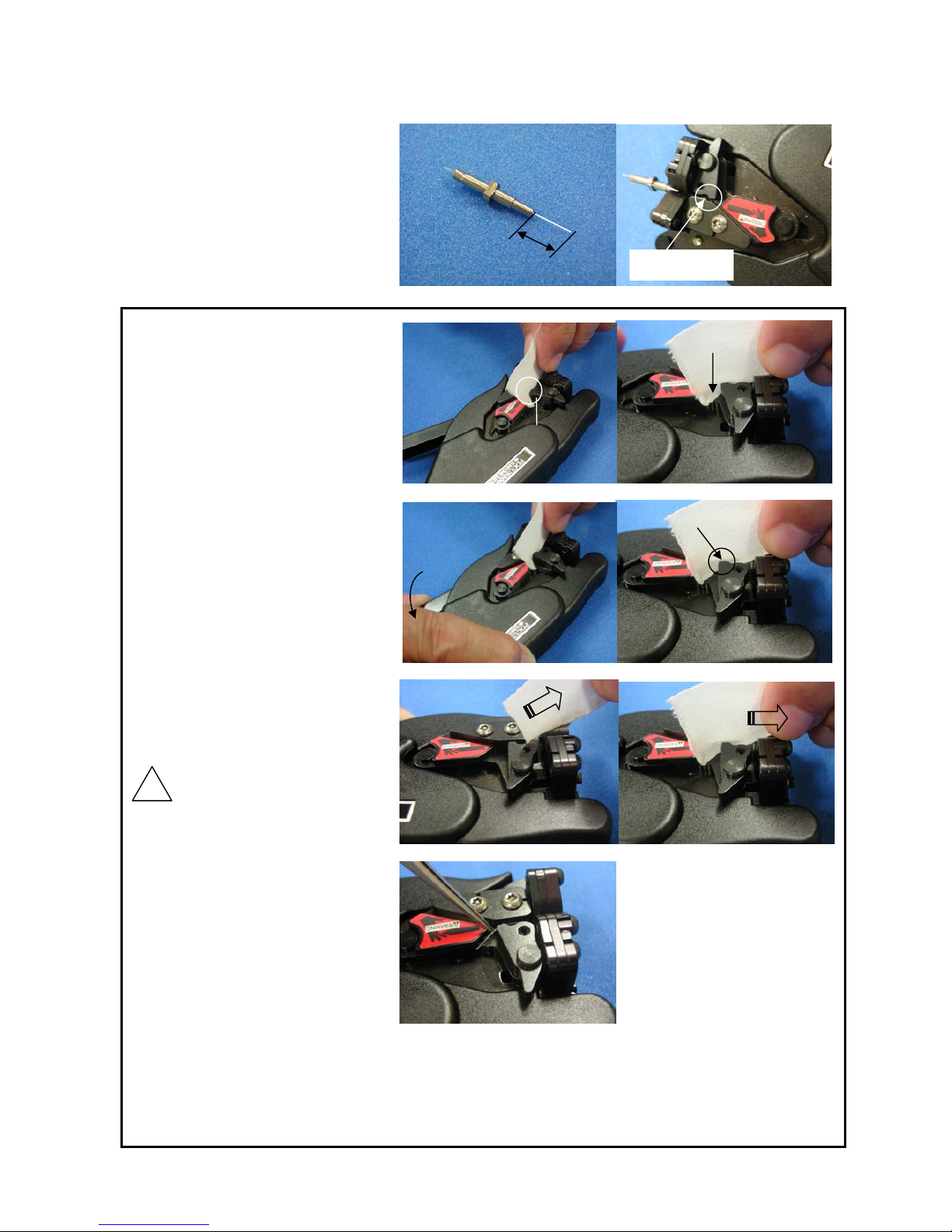
Cleaning the fiber chuck
In the case that fiber is broken
repeatedly at the chuck before
cutting, it is attributed to the fact
that chips or particles of optical
fibers are caught in the fiber chuck.
Please clean up the fiber chuck by
the following procedure.
(1) Insert a piece of clean cloth to
the gap between fiber chuck.
(Fig.69)
* Don’t use the dirty cloth or
breakable cloth. There is a
possibility of the trouble become
worse.
* Insert the cloth to the bottom. There
is a possibility that chips or particles
of optical fiber can’t be cleaned up.
(Fig.70)
(2) With inserting cloth, press up
the lever. It cause that cloth is
hold with chuck.(Fig.71)
* Please look that cloth is held with
chuck.(Fig.72)
(3) With holding cloth chucked,
pull cloth out of chuck obliquely
upward.(Fig.73)
* Don’t pull cloth in a horizontal
direction. There is a possibility that
the blade is damaged.(Fig.74)
* Cloth should be pulled out to the
end.
It is normal that cloth is caught by
cam.
* In the case that snips of cloth are
remained in chuck, insert tweezers
to pick it up.(Fig.75)
After you clean the fiber chuck, please check the problem is resolved by actually cutting the
fiber. In the case that the problem is not resolved despite several cleaning, please contact the sales
agency.
Fig.68
10mm
Fiber chuck
26
×
Bad Example
Hold
Fiber chuck
! Attention
Fig.67
Fig.71
Fig.75
Fig.73
Fig.69
Fig.70
Fig.74
Fig.72
 Loading...