

Model LED32SU20C

SAFETY
PRECAUTION
CONNECTIONS
INITIAL SETUP
WALL MOUNT
INSTALLATION
7
ACCESSORIES
IMPORTANT
SAFETY
INSTRUCTIONS
2
1
3
6
GETTING
STARTED
4
CONTROL
REFERENCE
GUIDE
5
8
TV SETUP
9
English
CONTENTS
12
1
2
3
3
Remote Contro l
Front View
Back View
4
5
6
Antenna Connecti on
AV Conne ctio n 7
YPbPr Connection 8
HDMl Co nnection 8
VGA Connec tion 9
Headphone Connection 9
Power Cord Connec tion 9
Op tic al audio output Connec tion 10
7
11
Putting The Unit On A Proper Plac e
Turning The Unit On For The First
Time
Source Selection
TV(CHANNEL) Menu
Picture Menu
Sound Menu
Time Menu
Setup Menu
LOCK(Parental) Menu
13
14
15
16
17
18
12
12

PC Formats
1O
DISPLAY
MODE
CONTENTS
Video Formats
19
20
11
12
SPECIFICATION
TROUBLESHOOTING
GUIDE
TV Sym ptom
21
22
SAFETY PRECAUTION
CAUTION MARKING WAS LOCATED AT THE REAR
OF THE APPARATUS.
WARNING: TO REDUCE THE RISK OF ELECTRIC
SHOCK, DO NOT REMOVE COVER (OR BACK)
NO USER SERVICEABLEPARTSINSIDE.
REFER SERVICING TO QUALIFIED SERVICE
PERSONNEL.
The lig htning flash with arr owhead sym bol ,
within an equil ateral triangle, i s inten ded to
alert the user to the presen ce of unins ulat ed
“dange rous vol tage “within the prod uct's en clos ure
that may be of sufficient magni tude to constitute a
risk of elect ric shock to person s.
The exclamation point wi thin an e quil ateral
Triangle is intended to alert the user to
The presence of important operating and
maintenance(servicing) instructions in the literature
accompanying the appliance.
CA UTION
DANGER OF EXPLOSION IF BATTERY IS
lNCORRECTLY REPLACED. REPLACE ONLY
WITH THE SAME OR EQUIVALENT TYPE.
USE OF CONTROLS OR ADJUSTMENTS OR
PERFORMANCE OF PROCEDURES OTHER
THAN THOSE SPECIFIED MAY RESULT IN
HAZARDOUS RADIATION EXPOSURE.
WA RNING :
TO REDUCE THE RISK OF FIRE OR ELECTRIC
SHOCK, DO NOT EXPOSE THIS APPLIANCE TO
RAIN OR MOISTURE.
TO REVENT FIRE OR SHOCK HAZARD, DO NOT
EXPOSE THIS UNITTO RAIN OR MOISTURE. DO
NOT PLACE OBJECTS FILLED WITH LIQUIDS ON
OR NEARTHIS UNIT.
SHOULD ANY TROUBLE OCCUR, DISCONNECT
THE AC POWER CORD AND REFER SERVICING
TO A QUALIFIED TECHNICIAN.
Do not use this unit in places that are extremely
hot, cold, dusty or humid.
Do not restrict the airflow of this unit by placing
it somewhere with poor airflow, by covering it
with a cloth, by placing it on bedding or
carpeting.
When connecting or disconnecting the AC power
cord, grip the plug and not the cord itself. Pulling
the cord may damage it and create a hazard.
When you are not going to use the unit for a long
period of time, disconnect the AC power cord.
NOTE: This unit has been tested and found to comply
with the limits for a Class B digital device, pursuant
to Part15 of the FCC Rules. These limits are designed
to provide reasonable protection against harmful
interference in a residential installation.
This unit generates, uses and can radiate radio
frequency energy and, if not installed and used in
accordance with the instructions, may cause harmful
interference to radio communication. However, there
is no guarantee that interference will not occur in a
particular installation. lf this unit does cause harmful
interference to radio or television reception, which
can be determined by turning the unit off and on, the
user is encouraged to try to correct the interference
by one or more of the following measures:
-Reorient or relocate the receiving antenna.
-lncrease the separation between the unit and
receiver.
-Connect the unit into an outlet on a circuit different
from that to which the receiver is connected.
1. Consult the dealer or an experienced
radio/TV technician for help.
Changes or modifications to this
unit not expressly approved by the party responsible
for compliance could void the user authority
to operate the unit.
“HDMl, the HDM1 logo and High-Definition Multimedia
Interface are trademarks or registered trademarks of
HDMl Licensing LLC.”
This equipment is a Class II or double insulated
electrical appliance. It has been designed in such a
way that it does not require a safety connection to
electrical earth.

1) Read these instructions.
2)
3)
4) Follow all instructions.
5) Do not use this apparatus near water
6)
7) Do not block any ventilation
8) Do not install near any heat sources
9) Do not defect the safety purpose of
10) Protect the power cord from being walked on
11) Only use attachments/ accessories specified
these instructions. Keep
all warnings. Heed
openings. install in accordance with
the manufacturer’s instructions.
such as radiators, heat registers, stoves,
or other apparatus (Including amplifiers)
that produce heat.
the polarized or grounding-type plug.
A polarized plug has
wider than the other.
A grounding type plug has two blades
and a third grounding prong.
The wide blade or the third prong is
provided for your safety.
lf the provided plug does not fit into your
wall outlet, consult an electrician for
replacement of the obsolete outlet.
or pinched particularly at plugs, convenience
receptacles. and the point where they exit
m the apparatus.
fro
by the manufacturer
IMPORTANT SAFETY INSTRUCTIONS
onl
y with a dry cloth. Clean
two blades with one
12) Use only with the cart, stand,
tripod, bracket, or table
specified by the manufacturer,
or sold with the apparatus.
When a cart is used, use caution when
moving the cart/apparatus combination to
avoid injury from tip-over.
13) Unplug this apparatus during lightning
Storms or when unused for long periods
of time.
14) Refer all servicing to quali
per
sonnel. Servicing is required when the
apparatus has been damaged in any way,
such as the power cord or plug is damaged,
liquid has been spilled or objects have fallen
into the apparatus, the apparatus has been
exposed to rain or moisture, does not operate
normally, or has been dropped.
fied service
15 )The mains plug is used as disconnect device,
the disconnect device shall remain readily operable.
Pl ease check and iden tify the supplied accessor ies .
Remote control
Battery(AAA)
ACCESSOR lES
Warranty Card
lnstruction Manual
Base stand and
4
base stand screws
USING THE REMOTE CONTROL
Point the remote control at the remote sensor located on the unit.
When there is a strong ambient light source, the performance of the infrared remote sensor ·may be
may be degraded, causing unreliable operation.
The recommended effective distance for remote operation is about16 feet (5 meters).
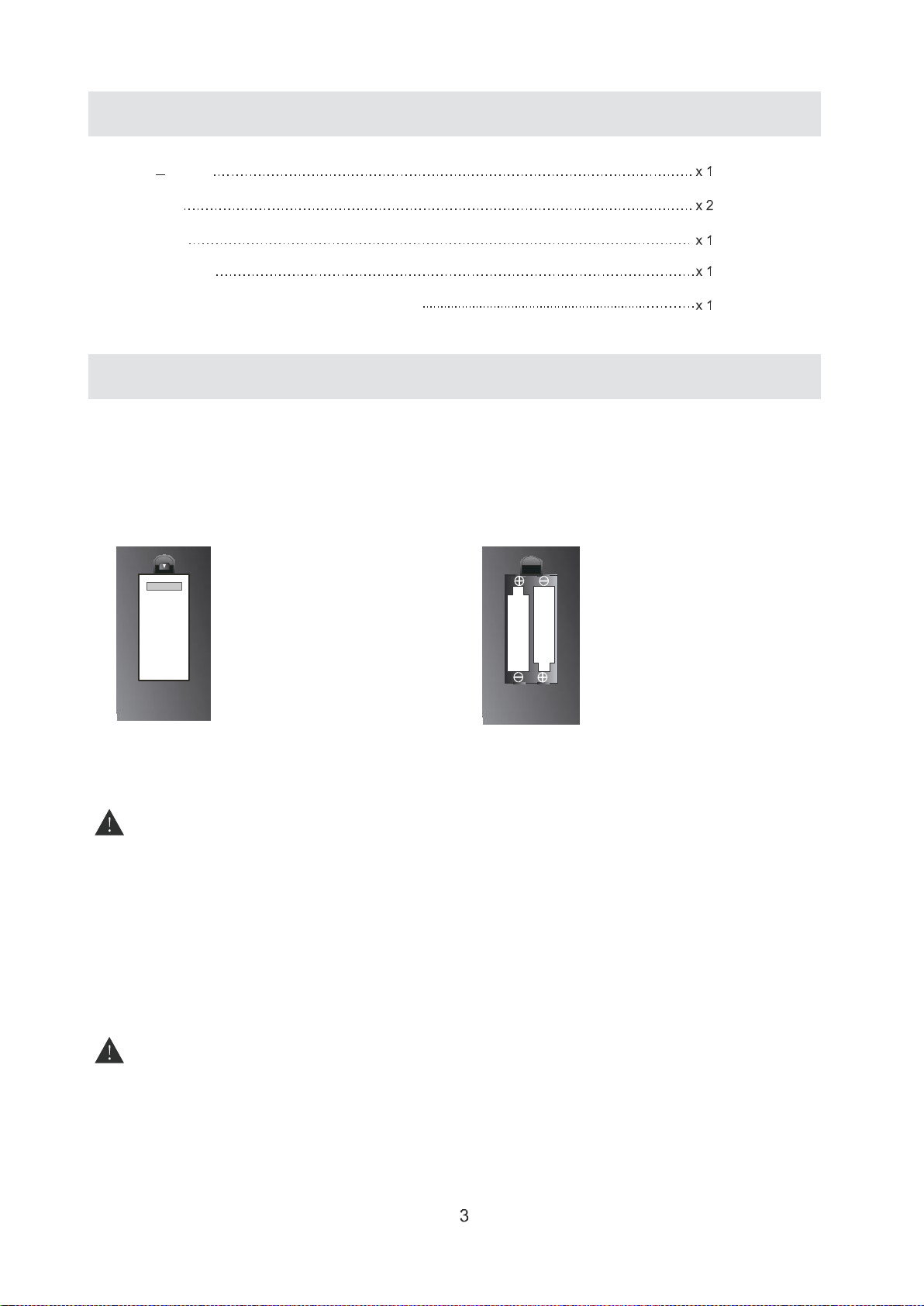
TO INSTALL THE BATTERIES
1.Open the battery door.
BATTERY REPLACEMENT
When the batteries become weak, the operating distance of the remote control is greatly
reduced and you will need to replace the batteries.
CAUTION:
Danger of explosion if battery is incorrectly replaced.
NOTES
·if the remote control is not going to be used for a long time, remove the batteries to avoid
damage caused by battery leakage corrosion.
·Do not mix old and new batteries. Do not mix ALKALINE, standard(CARBON-ZINC)
or
rechargeable(NICKEL-CADMIUM) batteries.
·Always remove batteries as soon as they become weak.
·Weak batteries can leak and severely damage the remote control.
WARNING:
Do not dispose batteries in a fire. Batteries may explode or leak.
Batteries shall not be exposed to excessive heat such as sunshine, fire or the like
GETTING STARTED
2.
insert 2"AAA"batteries
REMOTE CONTROL
9
6
POWER
MUTE
3
1 2
5
4
8
7
RET UR N
0
ENTER
DIS PL AY
EXIT
INP UT
MEN U
+
CH LIST
︽
VOL UME
FAV LIST
︽
CHA NNEL
SLEEP
SMODE
PMODE
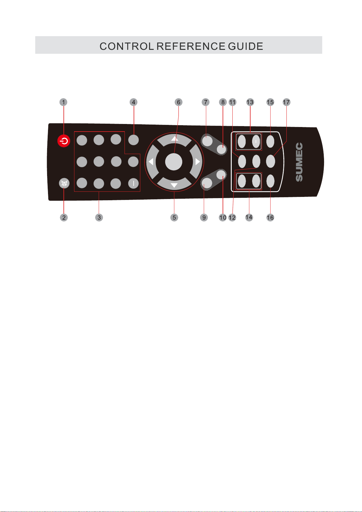
1 STANDBY
To switch on the TV or make the TV into standby mode.
2.MUTE
Press this button to mute or restore sound.
3. 0-9/-
Allows you to change the channel of the TV.
4 RETURN
Switches back and forth between the current and
previous channels.
5.UP/DOWN/LEFT/RIGHT
Moves the cursor upward/downward/to the left/to the
right when making a selection.
6.ENTER
Confirmation button, select the OSD menu option.
.DISPLAY
7
Press
to display the information window.
8. EXIT
Press this button to exit the on screen display.
9.MENU
Displays the OSD Menu of the TV.
1O.INPUT
Press to display and select the available video sources.
7) CH LIST
Press to display the Channel List.
8)
FAV LIST
Press this button to show the favourite list.
VOLUME(+/-)
13.
Increases/Decreases the Volume control.
Skips to the next/previous channel on TV mode.
SLEEP
15.
To select the amount of time before your TV turns
Off automatically.
PMODE
16.
Press to select the picture mode.
SMODE
17.
Press to change the audio mode.
4

Item
Description
1
MENU
2
INPUT
3
+ CH -
4
+ VOL -
5
Switch the TV on/standby.
Switch OSD menu ON/OFF.
Select input source.
Channel up/down when source is TV, or select a control while in
OSD menu.
Increase / Decrease sound volume or adjust a highlighted control while
OSD menu.
in
5

6 7 8 9
VGA IN
RF IN
(VIDEO/L/R)
L VIDEO/YR
2 3 4 5
Pb
Pr
Connect a 15-pin D-sub RGB cable to the RGB output of your
computer and the other end to the RGB input on the rear of the LED TV.
Connect this jack to your Cable or VHF/UHF antenna.
Only for software upgrade.
6

CONNECTIONS
CONNECTING A TV ANTENNA / CABLE / SATELLITE
To view television channels correctly, a signal must
be received from one of the following sources:
-An indoor or outdoor aerial antenna
-A cable system
-A satellite system
NOTE
For receiving over-the-air TV broadcasts, we
recommend that you use an external fixed antenna.
Should you require the use of a temporary antenna,
please ensure that you purchase an antenna with
sufficient ability to receive in weak signal areas.
Only when you are in close proximity to a trans
wil
l a temporary antenna reproduce a signal as
strongly as a fixed antenna.
mitter
CONNECTINGAN A/V DEVICE
To connect to other equipment such as a VCR, camcorder, satellite system or cable, etc.
CONNECTING DEVICES WITH A COMPOSITE
VIDEOOUTPUT
To connect A/V devices such as a VCR, video game system or camcorder.
Connecting to a VCR/Video Game System/ Camcorder
Connect the AUDlO /VIDEO cable (not included) as shown.
Make sure you connect the cable from the other equipment (AUDlO and VIDEO OUT) to this unit
(AV in)
NOTE
4) Please refer to the user manual
for the other equipment for
more information.
5) Composite video input
(shared with component)
7
CONNECTIONS
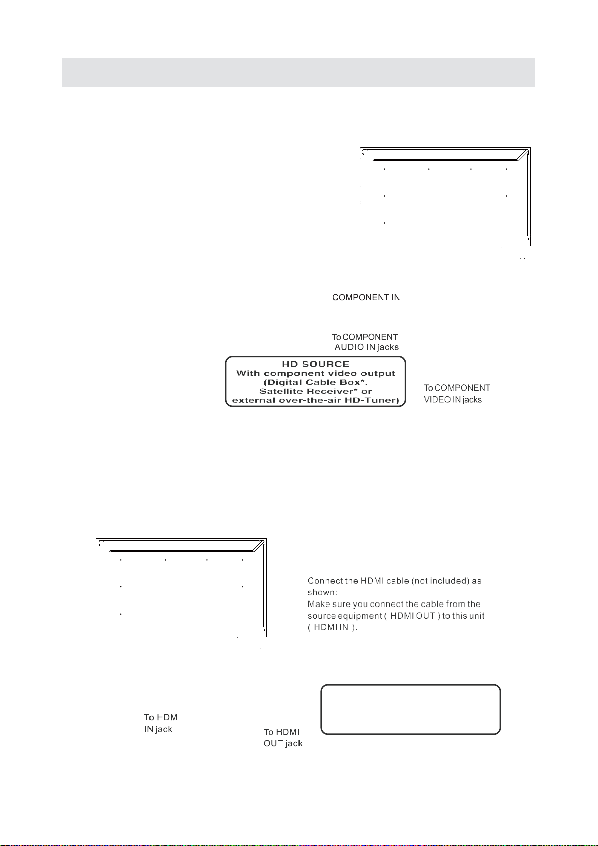
CONNECTING A HIGH-DEFINITION(HD)SOURCEUSING COMPONENT CONNECTION
High-Definition (HD) Devices with component video output must be connected to the YPbPr input.
Connect the component video cable and audio cable (not included) as shown.
Make sure you connect the component video cable and audio cable from the other equipment
(COMPONENTOUT and AUDlO OUT) to the unit COMPONENTIN.
NOTE
When connecting a DVD player to the television,
the picture resolution is solely dependen
the resolution supported by the DVD player attached
DVD player resolutions vary from 48Oi to 1080i.
and this television can support DVD players up to
a maximum resolution of 1080i.
t upon
May require a subscription
for receiving HD channels,
check with your cable/satellite
service provider for details.
To COMPONENT AUDlO
CONNECTING A HIGH-DEFINITION(HD) SOURCE USING HDMl CONNECTION
HDMl(High Definition Multimedia lnterface)supports both video and audio on a single digital connection
for use with DVD players, DTV, set-top boxes and other digital AV devices. HDMl was developed to provide
the technologies of High Bandwidth Digital Content Protection(HDCP) as well as Digital Visual lnterface
(DVl) in one specification. HDCP is used to protect digital content transmitted and received by
DVl
-compliant or HDMl compliant displays.
HDM l has the capability to support standard, enhanced or high-definition video plus standard to
multi-channel surround-sound audio. HDMl features include uncompressed digital video, a bandwidth of
up to 2.2gigabytes per second (with HDTV signals), one connector(instead of several cables and connectors) and
communication), between the AV source and AV devices such as DTVs.
To COMPONENT
VIDEO OUT jacks
OUT jacks
With component video output
external over-the-air HD-Tuner)
HD SOURCE
(Digital Cable Box*,
Satellite Receiver* or
8

CONNECTING A PC
Connectthe15-pin D-SUB PC/VGA connector
from your computer to the15-pin D-SUB PC/VGA
input on this unit using a monitor cable and an
audio cable (not included) as shown.
Make sure you connect the cable from the computer
(VGA and AUDlO- PC OUT) to this unit
(VGA and AUDlO- PC IN).
CONNECTING HEADPHONES
Tum down the volume before
connecting headphones to
the unit, then adjust the
volume to your desired level.
When headphones are
connected, no sound will come
from the
NOTE
Avoiding listening to sound at high
Levels for prolonged period of time.
This may be harmful to you and may
cause hearing loss.
CONNECTING THE POWER CORD
You can power on your TV unit before you make sure the power cord is inserted
well. At the same time, please check that the rated voltage of your unit matches your
local Voltage.
NOTE
·insert the power plug fully into the socket outlet.
he pow
(if t
cause fire.)
• Ensure that the power plug is easily accessible.
• Ensure the earth pin on the power plug is securely
connected to prevent electrical shock.
• Do not touch the power plug with a wet hand.
(This may cause electrical shock.)
• Do not use any power cord other than that
provided with this TV. (This may cause fire or
electrical shock.)
• Do not damage the power cord.
(A damaged
• Do not move the TV with the cord plugged in the
socket outlet.
• Do not place a heavy object on the cord or place
the cord near a high-temperature object.
• Do not twist the cord, bend it excessively, or stretch it,
• Do not pull on the cord. Hold onto the power plug body when disconnecting cord.
• Do not use a damaged power plug or socket outlet.
er plug is loose it could generate heat and
cord may cau
se fire or electrical shock.)
front
speakers.
9

COAX OUT
For BEST audio performance
Connecting to a Home Theater System
Dolby Digital can deliver optimal 2 channel
stereo or surround sound with five discrete
full range channels plus a sixth channel for
a subwoofer.
Enjoy optimal sound reproduction from your
system with a Dolby Digital amplifier that
incorporates a digital coaxial input. Connect
an optional digital cable directly to the
television's COAX audio output to listen
through all inputs except VGA.
(The VGA does not support digital audio)
How To Setup Digital Audio Output
Press the MENU button on the remote control
Press the right arrow button to select sound
Press the down▼ arrow button to highlight
Digital Audio Output Raw, PCM or Off.

4
4
Four mounting holes
(size M44 screw)
lNSTALLING / REMOVING THE BASE STAND
WARNING: The LED Display is very fragile, and must be protected at all times when removing the base
Be sure that no hard or sharp object or anything that could scratch or damage the LED display comes into
contact with it Do NOT exert pressure on the front of the unit at any time because the screen could crack
- Disconnect all cables or cords connected to the unit.
- Lay the unit down on a flat surface with the back side facing
cushioned material (such as a pillow or thick piece of foam) beneath the screen.
- To remove the base stand, loosen screws off the holes then pull downwards to release
the base stand
Stand.
up Please make sure to place a soft
MOUNTING ON THE WALL
This unit is VESA-compliant, and is designed to be wall-mounted with aVESA-compliant4” x4·
(1OOmm x1OOmm) mounting kit designed for flat-panel TVs (not supplied).
Length of screw should not exceed 1O mm (not supplied).
NOTE
Remove the base stand before mounting the unit on the wall
11
PUTTING THE UNIT ON A PROPER PLACE
When you tum on your television set for
the first time, be sure to place it on a solid
stable surface.
To avoid danger, do not expose the TV
to water, or a heat source
(e.g,lamp,candle,radiator).
Do not obstruct the ventilation grid
at the rear and be sure to leave sufficient
gaps around the unit.
TURNING THE UNIT ON FOR THE FIRST TIME
After you have initially connected your TV
antenna or cable,
turn the television ON.
A screen will display asking you to run a
Channel Auto Scan to search and
receive available local digital channels.
It is here where you will select antenna options
and run Channel Auto Scan.
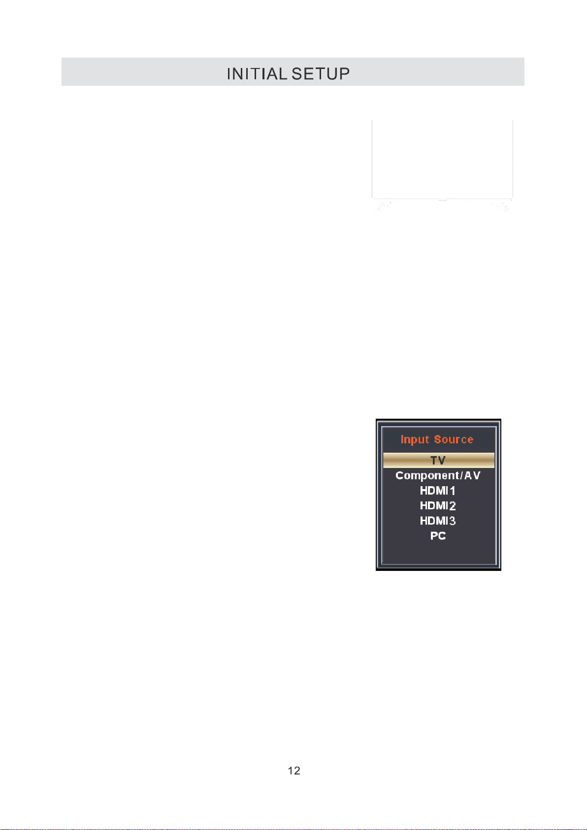
SOURCE SELECTION
1. Press the SOURCE button on the remote control.
2. Use the ▲or▼ button to select the options
(TV Component/ AV, HDMl, PC)
and select any of them using the OK button.
(The screen will change to your desired source).
Note:
Before watching please make sure all necessary
cables and devices are connected.

CHANNEL MENU
Press MENU button to display the main menu.
Press button to select CHANNEL in the main menu, it will high light the first option.
Air/Cable
This feature allows you to switch between air(such as using antenna) and cable
Auto Scan
This feature searches channels automatically for you.
Favorite
This feature gives the favorite list of channels added by you.
Show/Hide
This feature tells you if you have chosen for channel to be skipped.
Channel No.
This feature tells you what channel you are currently on.
Channel Label
This feature changes the name of the channel.
DTV Signal
Dynamic display the intensity of DTV
s
ignal, it always stand for the strong level for the DTV. User can not modify them.
Please Note:
The channel options are only available when you select TV as your SOURCE.
When you open the OSD menu on other sources (HDMl, Component, AV PC)
these options will be grayed out.
13

PICTURE MENU
Press MENU button to display the main menu.
Press
button to select PICTURE in the main menu,it will high light the first option.
Picture Mode
This feature changes various color or modes for the TV.
Contrast
This feature changes the difference between dark and bright objects
Brightness
This feature changes the picture's detail in dark colors
Color
This feature changes the amount of color in the picture
Tint
This feature changes the white balance of the color.
Sharpness
This feature changes the picture quality.
Color Temp
This feature adjusts the color temperature of the TV, gi
.
Cool
ving warm, normal
Blue Screen
After opening this option if there is no signal input, the screen turns blue .
14

AUDIO MENU
Press MENU button to display the main menu.
Press
button to select AUDIO in the main menu,it will high light the first option.
Sound Mode
Allow the selection of an audio-enhancement technique: Standard/Music/Movie/User/Sports.
Alternative: you may press the S.MODE button to select the sound mode directly
Bass
Control the relative intensity of lower-pitched sounds. (For User mode)
Treble
Control the relative intensity of higher-pitched sounds. (For User mode)
Balance
Adjust the relative volume of the speaker in a multiple speaker system
Surround Sound
Only for effect after connecting the surround test instrument.
Auto Volume
User can open when feel the sound not standard.it will control the maximum power output.
SPDIF Type
Only available under DTV channel and HDMI channel, it is unavailable under other channels.
the sound will output after connected the amplifier.
AUDIO LANGUAGE
This feature adjusts the digital second audio programming in digital channels.
TTS
Press left or right or enter key on the remote, will enter the TTS subpage item settings. The meaning of
the text read aloud, after opening can adjust the intensity and speed of sound.
TTS
Opening will turn on the TTS function, the machine will read the osd loudly according to your operation
wherever, else will not read the osd.
Volume
User can according to your hobby changed the volume level of read.
Speed
User can according to your hobby changed the speed level of read.
Pitch
User can according to your hobby changed the pitch level of read.
Please Note:
AUDIO LANGUAGE and MTS are dependent on the broadcasting station’s support and are only
available under the source TV.
15

TIME MENU
Press MENU button to display the main menu.
Press
button to select TIME in the main menu, it will high light the first option.
Sleep Timer
This timer automatically turns off the TV at the designated time.
Time Zone
This option adjusts the global time zone forth TV.
Daylight Saving Time
This option toggles the daylight saving time feature.
Please Note:
The TIME function will only keep accurate time if the TV is plugged into a power source. If
the TV is unplugged or the power strip is turned off, the TV·s time will not be accurate.

SETUP MENU
Press MENU button to display the main menu.
Press
button to select SETUP in the main menu,it will high light the first option.
Menu Language
This option changes the language of the TV’s OSD menu.
Transparency
This option changes the transparency of the menu allowing background TV images to show through.
Zoom Mode
Adjust the show width of picture area on the screen.
Noise Reduction
User fell the picture is not clear enough, then can adjust the value.
Advanced
It always stands for the preliminary menu include further sub page menu.
This option changes the source names to your personal preference.
Closed Caption
User can change the option when the program contains the subtitle.
DLC
Dynamic contrast adjustment. User can turn
Setup Wizard
This option enables the TV to show you the setup wizard of the TV again.
Restore Default
This option restores all the changes in the OSD menu back to the default factory settings.
Please Note:
Closed captioning is only available under AV and TV ports.
Closed captioning depends on your TV program’s support. Sometimes due to the TV channel or
n
the signal, closed captioni
g will not be available.
In United States, closed captioning under analog signals is CC1.
I n United States, closed captioning under digital signal is Service1.
on when feel the picture too brightness. It will power saving.
17

Set Password
this option allows you to set the Lock menu password
System Lock
This option enables parental locking and filtering for the TV.
US
This option filters US TV programming and movies,
Canada
This option filters CANADATV ratings,
RRT Setting
This feature is a download able rating filter based on TV broadcasts, With the transition of TV
broadcasts to digital, future changes, and enhancements in how TV shows are rated for content
are possible,
Reset RRT
This option resets the RRT settings.
Clear Lock
User can restore to the default v-chip settings by use it,
Please Note:
Please refer to RATINGS EXPLAINED for more information on ratings definitions.
Downloadable rating and clear downloadable data might be grayed out depending on the Tvs
stations support.
RRT5 options are based on TV broadcasts, if it is grayed out, then it is not available in your region.

NOTE:
This product does not support the display mode not listed above.
ln order to achieve the best display effect, please select the above-listed
5 displays modes input signal.
Because of the difference of display drivers output signal
(especially non-standard signal output), the display image may appear little
disturbance which can be adjusted on the PC menu.
To prolong this unit’s service life, please set your computer to power mana
gement mode.

NOTE:
The above listed formats are also related to the AV devices you are about to connect.
Before you connect this unit with others please read all instructions carefully and
make sure all necessary cables are connected.
This unit may be incompatible with some other formats which are not meet the
above conditions.
20

SPECIFICATION
32
31.5
1366 x 768
200
1200 :1(typ)
178(H)/178(V)
8 ms
AC-3,M/MTS
8W+8W
AC120V~,60Hz
55W
21

LED TV takes inside lighten phosphor. It may increase the
Make sure there are no unshielded electrical devices nearby
Check the PICTURE setting within the PICTURE menu.
in Color and not Black& White.
SYMPTOM
TV
Bad Picture(snow,
multiple images
distortion,blurry)
No sound.
Black and White
picture.
No picture or sound.
Colored patches of
picture.
TROUBLESHOOTING GUIDE
CAUSE (AND REMEDY)
Check the location of the antenna and adjust it if necessary.
Make sure the antenna cable is firmly connected.
Make sure all input cables are firmly connected.
increase the volume.
Check whether the mute function has been activated on the
Remote Control.
Check to make sure the program you are watching is broadcast
Make sure the unit is plugged in and turned on.
Make sure that the ATV mode is selected.
Try a new channel to check for possible station trouble.
Make sure the antenna is connected properly.
Increase
the volume.
Make sure the antenna or audio/video source device is
working properly.
Make sure all cables are firmly connected.
Check for local interference.
that are causing interference.
Under the influence of electrostatic phenomenon, the product
may malfunction and require user to power reset.
Turn the TV off for 30 minutes, then try it again.
Panel function key does
not respond correctly.
The display monitor’s
panel goes hot.
Unusual dots
Stripes on screen
The top of the monitor
gets hot.
Unable to select a
certain channel.
Disorder display
at power on.
Under the influence of electrostatic phenomenon, the product
may malfunction and require user to power reset.
Unplug and re-plug the AC power cord.
temperature of the screen in some occasions. It's not a defect.
Black dots and Bright points may appear on the LED screen.
This is a structural property of the LED panel and is not a defect
Adjust the impulse phase may decrease stripes. RGB in
lt may occur during long-time working. lt's not a defect.
The channel may be skipped. Choose this channel by
directly selecting the buttons from the remote control. ·
This may be caused because of a very short interval
between POWER OFF and ON.
Unplug the power and restart.
·
22
 Loading...