

Page 1
www.sulzer.com
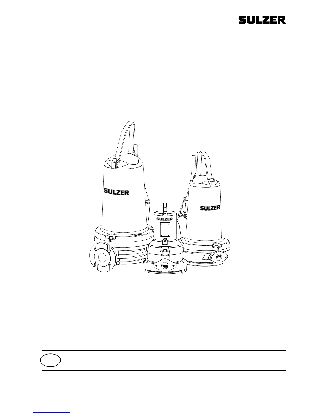
Submersible Grinder Pump Type ABS Piranha S10 - PE125
04/2016
EN
Installation, Operating and Maintenance Instructions
Page 2

2 Installation, Operating and Maintenance Instructions (Original Instructions)
Submersible Grinder Pump Type ABS Piranha S10 - PE125
Sulzer reserves the right to alter specications due to technical developments!
Submersible Grinder Pump Type ABS Piranha
S10/4W-50 S10/4W-50 E x PE30/2C- 50 Ex S10/4 -60 S10/4 -60 Ex PE25/2W-C-60 Ex PE80/2-E- 60 Ex
S12/ 2- 50 S12/ 2- 50 Ex PE 55/2E-50 Ex S10/4W-60 S10/4W-60 E x PE28/2-C-60 Ex PE100/2-E-60 Ex
S12/ 2W -50 S12/ 2W -50 Ex PE70/2E-50 Ex S20/2-60 S20/2- 60 Ex PE35/2-C- 60 Ex PE110/2-E-60 Ex
S13/4- 5 0 S13/4- 5 0 E x PE90/2E-50 Ex S20/2W-60 S20/2W-60 Ex PE35/2W-C-60 Ex PE125/2-E- 60 Ex
S17/2- 50 S17/2- 50 E x PE110/2E-50 Ex S26/2W-60 S26/2W-60 Ex PE45/2-C- 60 Ex
S17/2W-50 S17/2W - 50 E x S30/2-60 S30/2-60 Ex PE45/2W-C-60 Ex
S21/2-5 0 S21/2-50 Ex
S26/2-50 S26/2-50 Ex
Contents
1 Application areas �������������������������������������������������������������������������������������������������������������������������������������������������������3
1.1 Explosion-proof approval .............................................................................................................................................3
2 Safety ��������������������������������������������������������������������������������������������������������������������������������������������������������������������������� 3
2.1 Use of explosion-proof pumps in explosive zones. ...................................................................................................... 3
2.2 Special conditions for safe use of S-type, explosion-proof motors. ............................................................................3
3 Technical data ������������������������������������������������������������������������������������������������������������������������������������������������������������� 4
3.1 Nameplate ....................................................................................................................................................................4
4 General design features ������������������������������������������������������������������������������������������������������������������������������������������� 5
4.1 Design features Piranha-S ........................................................................................................................................... 5
4.2 Design features Piranha-PE ......................................................................................................................................... 6
5 Weights ������������������������������������������������������������������������������������������������������������������������������������������������������������������������7
5.1 Piranha-PE ...................................................................................................................................................................7
5.2 Chain (DIN 763) ............................................................................................................................................................ 7
6 Transport and storage ����������������������������������������������������������������������������������������������������������������������������������������������� 8
6.1 Tra n s por t ...................................................................................................................................................................... 8
6.2 Storage .........................................................................................................................................................................8
6.2.1 Moisture protection of motor connection cable ............................................................................................................ 8
7 Mounting and installation ����������������������������������������������������������������������������������������������������������������������������������������� 9
7.1 Installation example in concrete sump ......................................................................................................................... 9
7.2 Discharge line ............................................................................................................................................................... 9
8 Electrical connection ����������������������������������������������������������������������������������������������������������������������������������������������� 10
8.1 Temperature monitoring ............................................................................................................................................. 10
8.2 Seal monitoring ...........................................................................................................................................................10
8.3 Wiring diagrams .......................................................................................................................................................... 11
8.4 Checking direction of rotation ..................................................................................................................................... 12
8.5 Changing direction of rotation ................................................................................................................................... 12
9 Commissioning �������������������������������������������������������������������������������������������������������������������������������������������������������� 12
10 Maintenance and service ���������������������������������������������������������������������������������������������������������������������������������������� 13
10.1 General maintenance hints ........................................................................................................................................13
10.2 Shredding system ....................................................................................................................................................... 13
10.3 Oil filling and changing ............................................................................................................................................... 13
10.4 Oil-fill quantities .......................................................................................................................................................... 14
10.5 Bearings and Mechanical Seals ................................................................................................................................. 14
10.6 Maintenance of Lifting Stations in accordance with EN 12056. ................................................................................. 14
10.7 Cleaning ...................................................................................................................................................................... 14
10.8 Venting of the volute ................................................................................................................................................... 15
11 Troubleshooting Guide ��������������������������������������������������������������������������������������������������������������������������������������������15
Page 3

Installation, Operating and Maintenance Instructions (Original Instructions) 3
Submersible Grinder Pump Type ABS Piranha S10 - PE125
Symbols and notices used in this booklet:
Presence of dangerous voltage.
Non-compliance may result in personal injury.
Danger of an explosion occurring.
ATTENTION! Non-observance may result in damage to the unit or negatively affect its performance.
NOTE: Important information for particular attention.
1 Application areas
Piranha submersible grinder pumps have been designed for the pumping of sewage containing faecal matter
from buildings and sites where the location is below the sewer level.
In addition Piranha pumps are ideal for effective and economical pressurised dewatering using pipes of small
cross-sectional area, in private, municipal, and industrial applications.
The regulations of DIN EN 12056-4 as well as other local codes should be observed.
ATTENTION The maximum allowable temperature of the medium pumped is 40 °C.
1�1 Explosion-proof approval
The motors of the Piranha series have explosion-proof certication in accordance with Factory Mutual Class 1
Div. 1 Groups C and D (60 Hz, US), ATEX 2014/34/EC, II 2G Ex db IIB T4 Gb.
2 Safety
The general and specic health and safety requirements are described in detail in the “Safety Instructions for
Sulzer Products Type ABS” booklet. If anything is not clear or you have any questions as to safety make
certain to contact the manufacturer Sulzer.
This unit can be used by children aged 8 years and above, and persons with reduced
physical, sensory, or mental capabilities, or lack of experience and knowledge, when they
have been given supervision or instruction concerning the safe use of the device and
understand the hazards involved. Children must not play with the appliance. Cleaning and
user maintenance should not be performed by children without supervision.
2�1 Use of explosion-proof pumps in explosive zones�
1. Explosion-proof submersible pumps may only be operated with the thermal sensing system connected.
2. If ball type oat switches are used, these must be connected to an intrinsically safe electrical circuit
“Protection type EX (i)” in accordance with VDE 0165.
3. Dismantling and repair of submersible explosion-proof motors may only be carried out by approved
personnel in specially approved work shops.
2�2 Special conditions for safe use of S-type, explosion-proof motors�
1. The integral supply cable shall be suitably protected from mechanical damage and terminated within an
appropriate termination facility.
2. Pump motors rated for use with 50/60 Hz sinusoidal supplies shall have the thermal protection devices
connected in such a way that the machine is isolated from the supply in the event of the stator reaching
130 °C
.
3. Pump motors rated for use with variable frequency or non-sinusoidal supplies shall have the thermal
protection devices connected in such a way that the machine is isolated from the supply in the event of the
stator reaching 100 °C for T4 classied machines, or 160 °C for T3 classied machines.
4. These motor units are not intended for user service or repair, any operation that may affect the explosion
protection characteristics should be referred to the manufacturer. The maximum permitted amepath gaps
are tighter than those specied in EN 60079-1:2014.
Page 4
4 Installation, Operating and Maintenance Instructions (Original Instructions)
Submersible Grinder Pump Type ABS Piranha S10 - PE125
3 Technical data
Detailed technical information is available in the technical data sheet Sulzer Piranha submersible grinder pump
08 - 125 which can be downloaded from www.sulzer.com > Products & Services > Pumps and Systems.
Maximum noise level ≤ 70dB. This may be exceeded in certain circumstances.
3�1 Nameplate
We recommend that you record the data from the nameplate on the pump in the corresponding form below, and
maintain it as a source of reference for the ordering of spare parts, repeat orders and general queries.
Always state the pump type, item no. and serial no. in all communications.
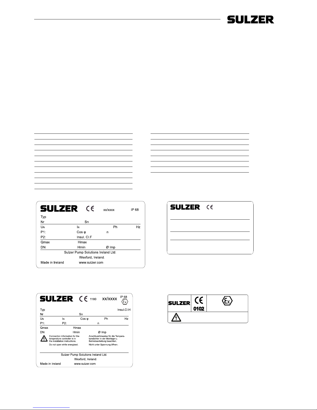
Piranha-PE pumps are rated for use in hazardous locations (Ex) as standard, and are tted with a standard
nameplate containing technical data and a secondary nameplate to certify that the pump is Ex rated (examples
below).
If a Piranha-PE pump is serviced or repaired in a workshop that is not Ex approved then it must no longer be
used in hazardous locations and the Ex nameplate must be removed.
Standard nameplate
1003-03
Typ
Nr Sn
UN IN Ph Hz
P1: Cos φ n
P2: Weight
Qmax Hmax
DN Hmin Ø Imp
Sulzer Pump Solutions Ireland Ltd.
Wexford, Ireland.
Made in Ireland www.sulzer.com
IP 68
xx/xxxx
1231-00
Piranha-PE
Piranha-S
Ex nameplate
Baseefa 03ATEX07..X II 2G Ex db IIB T4 Gb
1001-04
0102
Do not open while energized
Nich t unter Spannung ö ffnen
II 2G Ex db IIB T4 Gb
1232-01
Piranha-PE
Piranha-S
Legend
Typ Pump type
Nr Item number
Sn Serial number
xx/xxxx Production date (week/year)
U
n
Rated voltage V
I
n
Rated current A
Ph Number of phases
Hz Frequency Hz
P1 Rated input power kW
P2 Rated output power kW
n Speed r/min
Cos φ Power factor pf
NEMA NEMA code
Qmax Maximum ow m
3
/h
Hmax Maximum head m
Ø Imp. Impeller diameter mm
DN Discharge diameter mm
Page 5
Installation, Operating and Maintenance Instructions (Original Instructions) 5
Submersible Grinder Pump Type ABS Piranha S10 - PE125
4 General design features
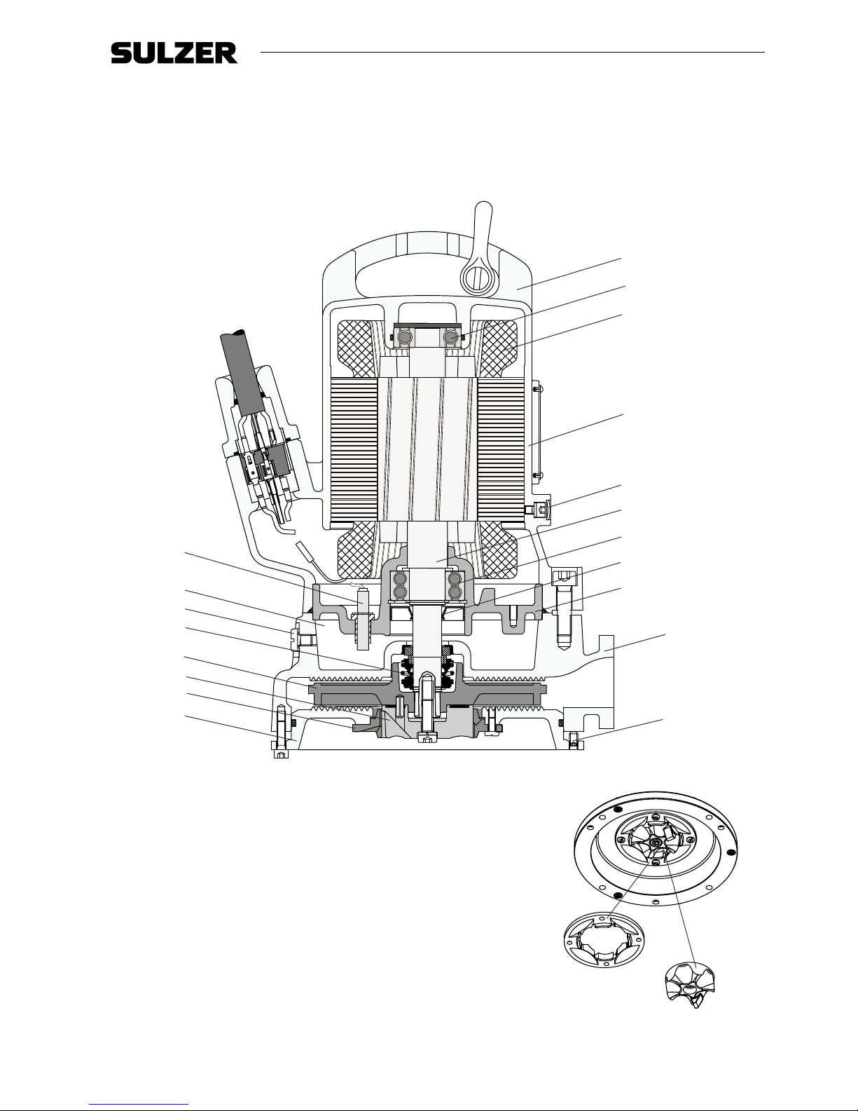
Submersible grinder pump tted with a shredding system hydraulic.
The shredding system is located before the impeller and consists of a shredding rotor in combination with a
stationary cutting ring xed to a spiral bottom plate.
4�1 Design features Piranha-S
1
5
6
7
9
3
8
10
11
12
13
14
15
16
17
19
18
4
2
1233-00
Shredding system
1 Cast iron lifting handle and
steel shackle
2 Upper bearing - single row
3 Motor with thermal sensors
4 Motor housing
5 Motor chamber pressure
test point
6 Stainless steel shaft
7 Lower bearing - double row
8 Oil-lubricated lip seal
9 Bearing housing
10 Volute
11 Bottom plate adjustment
screw
12 Moisture sensor (DI)
13 Oil chamber
14 Oil chamber drain plug/
pressure test point
15 Mechanical seal
16 Impeller
17 Shredding rotor
18 Cutting ring (xed to bottom
plate)
19 Bottom plate
17
18
1234-00
Page 6
6 Installation, Operating and Maintenance Instructions (Original Instructions)
Submersible Grinder Pump Type ABS Piranha S10 - PE125
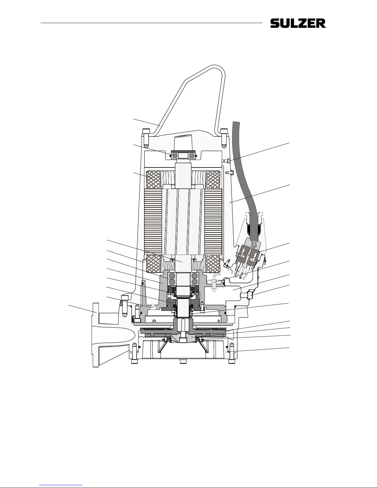
4�2 Design features Piranha-PE
Submersible grinder pump tted with a shredding system hydraulic and a Premium Efciency motor.
18
7
8
9
10
12
13
14
15
14
16
11
1
3
4
5
6
19
20
2
17
21
1235-00
1 Pressure release screw
2 Motor housing
3 10-pole terminal block
4 Moisture sensor (DI)
5 Oil chamber
6 Oil chamber drain plug/
pressure test point
7 Stainless steel lifting hoop
8 Upper bearing - single row
9 Motor with thermal sensors
10 Stainless steel shaft
11 Motor chamber
12 Lower bearing - double row
13 Bearing housing
14 Mechanical seals
15 Seal holding plate
16 Motor chamber drain plug/
pressure test point
17 Volute
18 Impeller
19 Shredding rotor
20 Cutting ring (xed to bottom
plate)
21 Bottom plate
Page 7
Installation, Operating and Maintenance Instructions (Original Instructions) 7
Submersible Grinder Pump Type ABS Piranha S10 - PE125
5 Weights
NOTE: Weight on nameplate is for pump and cable only.
5�1 Piranha-PE
Pedestal
bracket
and
fasteners
Skirtbase
(transportable)
Cable Pump
(without
cable)
kg (lbs) kg (lbs) kg (lbs) kg (lbs)
Piranha
400 V 1)208 V 2)230 V 2)460 V 2)600 V
2)
50 Hz
PE 30/2D 4 (9) 4 (9) 0.3 (0.7) - - - - 90 (198)
PE 55/2D, PE 70/2D 7 (15) 4 (9) 0.4 (0.9) - - - - 130 (287)
PE 90/2D, PE 110/2D 7 (15) 4 (9) 0.4 (0.9) - - - - 150 (331)
60 Hz
PE 25/2W 4 (9) 4 (9) - 0.18 (0.4) 0.18 (0.4) - - 80 (176)
PE 28/2D 4 (9) 4 (9) - 0.14 (0.3) 0.14 (0.3) 0.14 (0.3) 0.14 (0.3) 80 (176)
PE 35/2W 4 (9) 4 (9) - 0.23 (0.5) 0.23 (0.5) - - 80 (176)
PE 35/2D 4 (9) 4 (9) - 0.18 (0.4) 0.14 (0.3) 0.14 (0.3) 0.14 (0.3) 80 (176)
PE 45/2W 4 (9) 4 (9) - 0.23 (0.5) 0.23 (0.5) - - 80 (176)
PE 45/2D 4 (9) 4 (9) - 0.23 (0.5) 0.18 (0.4) 0.18 (0.4) 0.14 (0.3) 80 (176)
PE 80/2D 7 (15) 4 (9) - 0.23 (0.5) 0.23 (0.5) 0.18 (0.4) 0.14 (0.3) 130 (287)
PE 100/2D, 7 (15) 4 (9) - 0.23 (0.5) 0.23 (0.5) 0.23 (0.5) 0.18 (0.4) 160 (353)
PE 110/2D 7 (15) 4 (9) - 0.23 (0.5) 0.23 (0.5) 0.23 (0.5) 0.23 (0.5) 160 (353)
PE 125/2D 7 (15) 4 (9) - 0.23 (0.5) 0.23 (0.5) 0.23 (0.5) 0.23 (0.5) 160 (353)
1)
Weight per metre. 2) Weight per foot.
5�2 Chain (DIN 763)
Size (mm) 5 x 35 6 x 42 8 x 52 10 x 65 13 x 82
Weight per metre (kg) 0.43 0.63 1.10 1.75 2.95
Weights of accessories, other than or in addition to those listed, must also be included when
specifying the working load of any lifting equipment. Please consult with your local Sulzer
representative prior to installation.
Page 8
8 Installation, Operating and Maintenance Instructions (Original Instructions)
Submersible Grinder Pump Type ABS Piranha S10 - PE125
6 Transport and storage
6�1 Transport
During transport, care should be taken that the pump is not dropped or thrown.
The unit is tted with a lifting device to which a chain and shackle may be attached for transport purposes.
The unit should never be raised or lowered by the power cable.
Take note of the weight of the entire unit. The hoist and chain must be adequately dimensioned for
that weight and must comply with the current valid safety regulations.
All relevant safety regulations as well as general good technical practice must be complied with.
6�2 Storage
1. During long periods of storage the pump should be protected from moisture and extremes of cold or heat.
2. To prevent the mechanical seals from sticking it is recommended that occasionally the impeller is rotated by
hand.
3. If the pump is being taken out of service the oil should be changed before storage.
4. After storage the pump should be inspected for damage, the oil level should be checked, and the impeller
checked to ensure it rotates freely.
6�2�1 Moisture protection of motor connection cable
The motor connection cables are protected against the ingress of moisture along the cable by having the ends
sealed at the factory with protective covers.
ATTENTION! The ends of the cables should never be immersed in water as the protective covers
only provide protection against water spray or similar (IP44) and are not a water tight
seal. The covers should only be removed immediately prior to connecting the pumps
electrically.
During storage or installation, prior to the laying and connection of the power cable, particular attention should
be given to the prevention of water damage in locations which could ood.
ATTENTION! If there is a possibility of water ingress then the cable should be secured so that the
end is above the maximum possible ood level. Take care not to damage the cable or
its insulation when doing this.
Page 9
Installation, Operating and Maintenance Instructions (Original Instructions) 9
Submersible Grinder Pump Type ABS Piranha S10 - PE125
7 Mounting and installation
The regulations covering the use of pumps in sewage applications together with all regulations
involving the use of explosion-proof motors should be observed.The cable ducting to the control panel
should be sealed off in a gas-tight manner by the use of a foaming material after the cable and control
circuits have been pulled through. In particular the safety regulations covering work in enclosed areas
in sewage plants should be observed together with general good technical practice.
For the Piranha transportable version, arrange the cable run so that the cables will not be kinked or nipped.
Connect the discharge pipe and cable (see section ”Electrical Connection”). Place the pump on a rm surface
which will prevent it from overturning or burrowing down. The pump can also be bolted down to the base or
suspended slightly by the lifting handle. Hoses, pipes and valves must be sized to suit the pump performance.
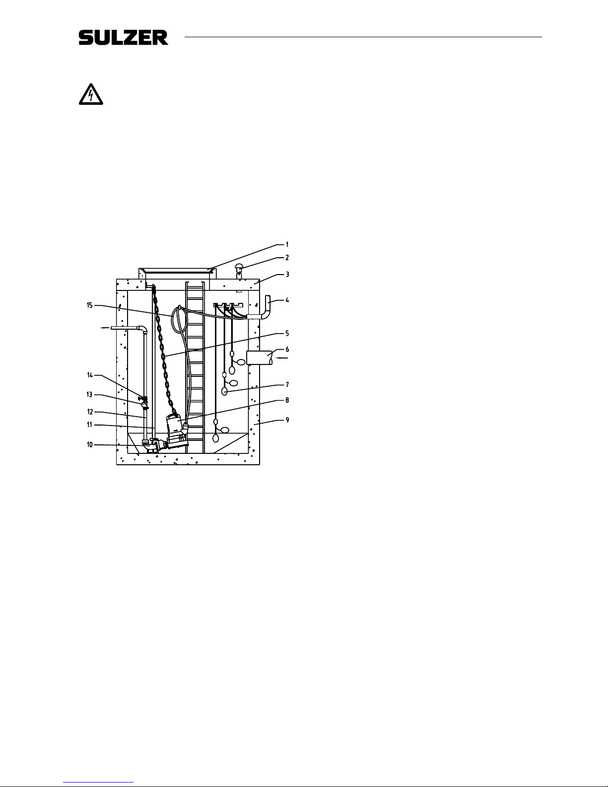
7�1 Installation example in concrete sump
1 Sump cover
1005-00
2 Venting line
3 Sump cover
4 Protective duct to the
control panel for cable
5 Chain
6 Inow line
7 Ball type oat switch
8 Submersible pump
9 Concrete sump
10 Pedestal
11 Guide tube*
12 Discharge line
13 Non-return valve
14 Gate valve
15 Power cable to motor
* The tting of a guide tube is compulsory when the pump is installed on a pedestal.
ATTENTION For those applications subject to Regulation DIN 1986, a backwash loop should be
provided in the discharge line.
7�2 Discharge line
The discharge line must be installed in compliance with the relevant regulations.
DIN 1986/100 and EN 12056 applies in particular to the following:
- The discharge line should be tted with a backwash loop (180° bend) located above the backwash level and
should then ow by gravity into the collection line or sewer.
- The discharge line should not be connected to a down pipe.
- No other inows or discharge lines should be connected to this discharge line.
ATTENTION! The discharge line should be installed so that it is not affected by frost.
The vent line is connected by means of a push-on sleeve to the vertical outlet at the top of the collection tank.
It should be of constant cross-section (min. DN 70) and should have a continuous rise to above roof level.
Page 10
10 Installation, Operating and Maintenance Instructions (Original Instructions)
Submersible Grinder Pump Type ABS Piranha S10 - PE125
8 Electrical connection
Before commissioning an expert should check that one of the necessary electrical protective devices
is available. Earthing, neutral, earth leakage circuit breakers, etc. must comply with the regulations
of the local electricity supply authority and a qualied person should check that these are in perfect
or der.
ATTENTION! The power supply system on site must comply with VDE or other local regulations
with regard to cross-sectional area and maximum voltage drop. The voltage stated on
the nameplate of the pump must correspond to that of the mains
The power supply cable must be protected by an adequately dimensioned slow-blow fuse corresponding to the
rated power of the pump.
The incoming power supply as well as the connection of the pump itself to the terminals on the control
panel must comply with the circuit diagram of the control panel as well as the motor connection
diagrams and must be carried out by a qualied person.
All relevant safety regulations as well as general good technical practice must be complied with.
ATTENTION! For use in the open air, the following VDE regulations apply:
Submersible pumps used outdoors must be tted with a power cable of at least 10 m length. Other regulations
may apply in different countries.
For pumps intended to be used in outdoor fountains, garden ponds and similar places, the pump is to be
supplied through a residual current device (RCD) having a rated residual operating current not exceeding
30 mA.
NOTE: Please consult your electrician.
8�1 Temperature monitoring
Thermal sensors in the stator windings protect the motor from overheating.
Piranha motors are tted with bimetallic thermal sensors in the stator as standard in Piranha-PE and
Ex Piranha-S, and as an option in non-Ex Piranha-S.
ATTENTION: Explosion-proof pumps may only be used in explosive zones with the thermal
sensors connected.
8�2 Seal monitoring
Piranha-PE and Piranha-S pumps are supplied with a moisture sensor (DI), to detect and alert to the ingress of
water into the motor and oil chambers.
DI is optional with Piranha-S, and in the Ex-version monitors only the motor chamber.
ATTENTION: If the DI seal monitoring is activated the unit must be immediately taken out of
service. Please contact your Sulzer Service Centre.
NOTE!
Running the Piranha-PE pump with the thermal and/or moisture sensors
disconnected will invalidate related warranty claims.
Page 11
Installation, Operating and Maintenance Instructions (Original Instructions) 11
Submersible Grinder Pump Type ABS Piranha S10 - PE125
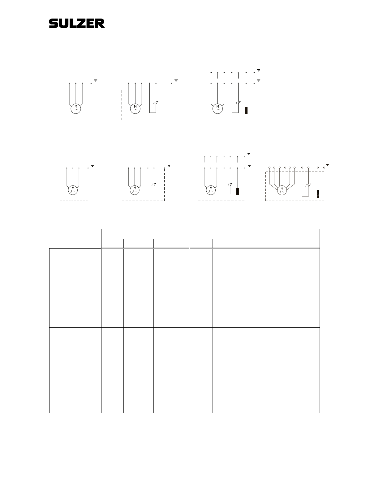
8�3 Wiring diagrams
Single phase:
112 3 4 5 6
60 Hz:PE R S C 1 2 3
DIF1 FO R
50 Hz:
S C PE
112 3 4 5
F1 FO R50 Hz: S C PE
R C S PE
1
blk gry br
50 Hz:
2. 3. 1.
NOTE:
R = Run
S = Start
C = Neutral (Common)
F1, F0 = Thermal sensor
DI = Seal monitor
PE = Earth
blk = Black
gry = Grey
br = Brown
1236-00
Three phase:
U1 V1 W1 V2 W2 U2 F1 FO DI PE
1 2 3 4 5
6 7 8 9
U V W F1 FO DI PE
1 2 3 4 5 6
60 Hz:PET1 T2 T3 1 2 3
50 Hz:
U V W F1 FO PE
1 2 3 4 5
50 Hz:
U V W PE
50 Hz:
blk gry br
6.
5.
7.
4.
1237-00
Single phase Three phase
1� 2� 3� 4� 5� 6� 7�
Piranha 50 Hz
S10/4,
S12/2,
S17/2
S10/4-Ex,
S12/2-Ex,
S17/2-Ex
S10/4
S10/4-Ex,
S12/2,
S12/2-Ex,
S17/2,
S17/2-Ex
S13/4,
S12/2,
S17/2,
S21/2,
S26/2
S13/4-Ex
S12/2-Ex,
S17/2-Ex,
S21/2-Ex,
S26/2-Ex
S13/4
S13/4-Ex,
S12/2,
S12/2-Ex,
S17/2,
S17/2-Ex,
S21/2,
S21/2-Ex,
S26/2,
S26/2 (DO5)*
S26/2-Ex,
PE30/2C-Ex
PE55/2E-Ex
PE70/2E-Ex,
PE90/2E-Ex,
PE110/2E-Ex
Piranha 60 Hz
- -
S10/4
S10/4-Ex,
S20/2,
S20/2-Ex,
S26/2,
S26/2-Ex,
PE25/2C-Ex,
PE35/2C-Ex,
PE45/2C-Ex
- -
S10/4
S10/4-Ex,
S20/2,
S20/2-Ex,
S30/2,
S30/2-Ex,
PE28/2C-Ex,
PE35/2C-Ex,
PE45/2C-EX,
PE80/2E-EX
PE100/2E-EX
PE110/2E-EX,
PE125/2E-EX
-
* 400/695V
ATTE NTI O N: It is important to use the correct capacitors with single phase pumps, use of incorrect capacitors will lead to motor burn-out.
Page 12
12 Installation, Operating and Maintenance Instructions (Original Instructions)
Submersible Grinder Pump Type ABS Piranha S10 - PE125
8�4 Checking direction of rotation
When three phase units are being commissioned for the rst time and also when used on a new site, the
direction of rotation must be carefully checked by a qualied person.
When checking the direction of rotation, the unit should be secured in such a manner that no danger
to personnel is caused by the rotating impeller, or by the resulting air ow. Do not place your hand into
the hydraulic system!
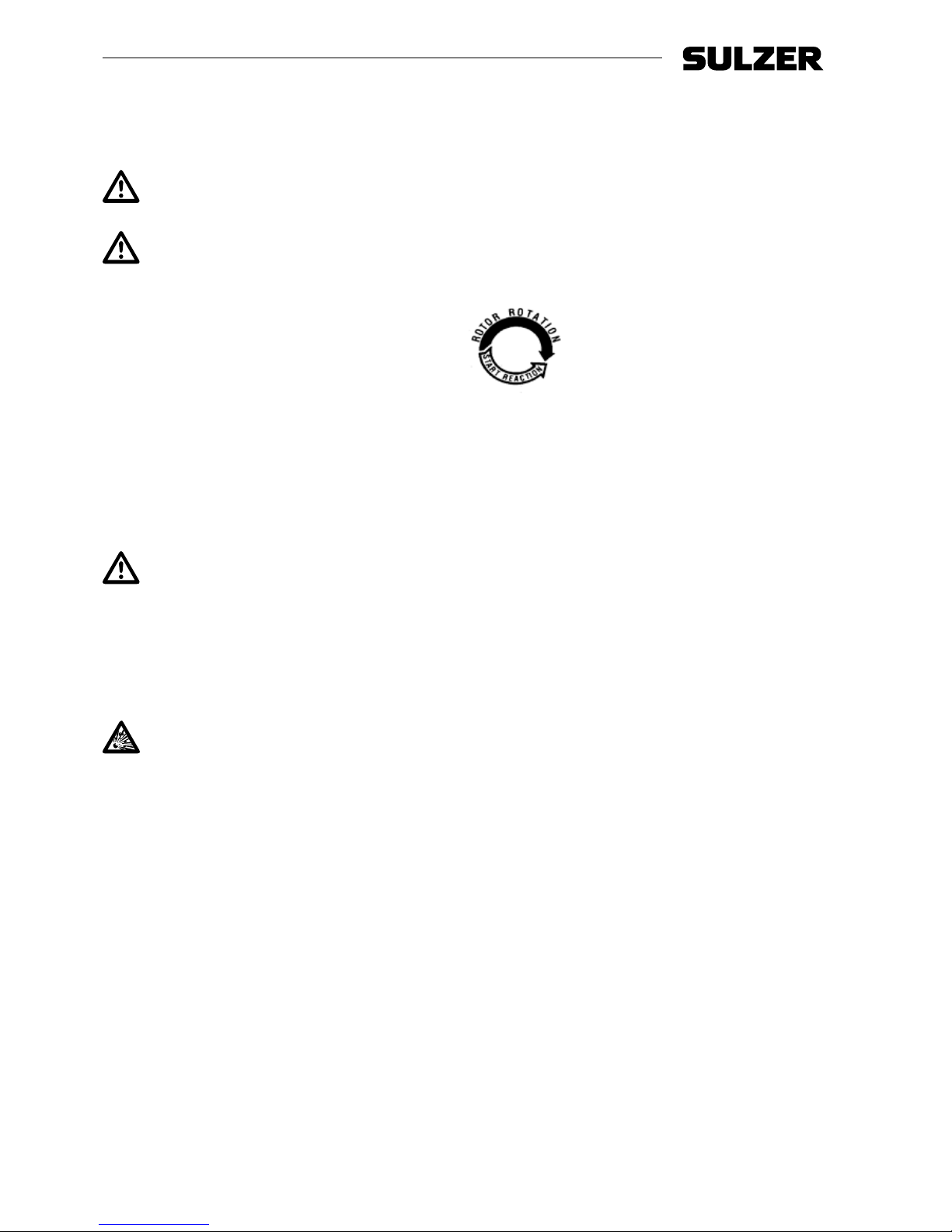
When checking the direction of rotation, or when starting the unit, pay attention to the STA R T
REACTION. This can be very powerful and cause the pump to jerk in the opposite direction to the
direction of rotation.
ATTENTION:
When viewed from above, the
direction of rotation is correct
if the impeller rotates in a
clockwise manner.
NOTE:
The start reaction is
anti-clockwise.
NOTE: If a number of units are connected to a single control panel then each unit must be
individually checked.
ATTENTION! The mains supply to the control panel should have a clockwise rotation. If the leads
are connected in accordance with the circuit diagram and lead designations, the
direction of rotation will be correct.
8�5 Changing direction of rotation
The direction of rotation should only be altered by a qualied person.
If the direction of rotation is incorrect then this is altered by changing over two phases of the power supply cable
in the control panel. The direction of rotation should then be rechecked
NOTE: The direction of rotation measuring device monitors the direction of rotation of the
mains supply or that of an emergency generator.
9 Commissioning
In explosive zones, care must be taken that during switching on and operation, the pump section is
lled with water or alternatively is submerged or under water. Ensure that the minimum submergence
given in the data sheet is observed. Other types of operation e.g. snore operation or dry running are not
allowed.
Before commissioning the unit should be checked and a functional test carried out. Particular attention should
be paid to the following:
- Have the electrical connections been carried out in accordance with regulations?
- Have the thermal sensors been connected?
- Is the seal monitoring device (where tted) correctly installed?
- Is the motor overload switch correctly set?
- Have the power and control circuit cables been correctly tted?
- Was the sump cleaned out?
- Have the inow and outows of the pump station been cleaned and checked?
- Is the direction of rotation correct - even if run via an emergency generator?
- Are the level controls functioning correctly?
- Are the required gates valves (where tted) open?
- Do the non-return valves (where tted) function easily?
Page 13
Installation, Operating and Maintenance Instructions (Original Instructions) 13
Submersible Grinder Pump Type ABS Piranha S10 - PE125
10 Maintenance and service
To avoid danger if the power cable is damaged, it must be replaced by the manufacturer or its service
agent or a similarly qualied person.
Before commencing any maintenance work the unit should be completely disconnected from the
mains by a qualied person and care should be taken that it cannot be inadvertently switched back
on.
Servicing must only be carried out by qualied personnel.
When carrying out any repair or maintenance work, the safety regulations covering work in enclosed
areas of sewage installations as well as good general technical pratices should be followed.
NOTE The maintenance instructions given here are not designed for “do-it-yourself” repairs
as special technical knowledge is required.
10�1 General maintenance hints
Sulzer submersible pumps are reliable quality products, each being subjected to careful nal inspection.
Lubricated-for-life ball bearings, together with monitoring devices, ensure optimum pump reliability provided that
the pump has been connected and operated in accordance with the operating instructions. However, should a
malfunction occur, do not improvise, but ask your Sulzer Customer Service Department for assistance.
This applies particularly if the pump is continually switched off by the current overload in the control panel, by
the thermal sensors of the thermo-control system, or by the seal monitoring system (DI).
Regular inspection and care is recommended to ensure a long service life. Service intervals vary for Piranha
pumps depending on installation and application. For recommended service interval details contact your local
Sulzer Service Centre. A maintenance contract with our Service Department will guarantee the best technical
service.
When carrying out repairs, only original spare parts supplied by the manufacturer should be used.
Sulzer warranty conditions are only valid provided that any repair work has been carried out in an Sulzer approved workshop and where original Sulzer spare parts have been used.
NOTE Piranha-PE pumps are rated for use in hazardous locations (Ex) as standard and feature
a secondary Ex nameplate containing EX data. If a Piranha-PE pump is serviced or repaired
in a workshop that is not Ex approved then it must no longer be used in hazardous locations
and the Ex nameplate must be removed.
10�2 Shredding system
The shredding system of the Piranha is a wearing part, and as such may need to be replaced. A reduction
in cutting performance can reduce the output. We recommend that the shredding system is inspected
regularly. This is particularly so if sewage containing sand is being pumped. Regular inspection and care is
recommended to ensure a long service life.
The Sulzer Service Organisation would be pleased to advise you on any applications you may have and to
assist you in solving your pumping problems.
10.3 Oilllingandchanging
The motor chamber (Piranha-PE), and the oil chamber between the motor and the hydraulic section (Piranha
-PE & Piranha-S), have been lled at manufacture.
An oil change is only necessary:
• at specied service intervals (for details contact your local Sulzer Service Centre).
• if the DI moisture sensor detects an ingress of water into the oil chamber or motor chamber.
• after repair work that requires draining of the oil.
• if the pump is being taken out of service the oil should be changed before storage.
Page 14

14 Installation, Operating and Maintenance Instructions (Original Instructions)
Submersible Grinder Pump Type ABS Piranha S10 - PE125
10.3.1 Instructionsonhowtodrainandlltheoilchamber
1. Loosen the plug screw enough to release any pressure that may have built-up, and re-tighten (for location
see pages 5 and 6).
Before doing so, place a cloth over the plug screw to contain any possible spray of oil as the pump
de-pressurises.
2. Place the pump in a horizontal position on a waste oil sump with the drain hole underneath.
3. Remove the plug screw and seal ring from the drain hole.
4. After the oil is fully drained rotate the pump so that the drain hole is positioned to the top.
5. Select the required volume from the oil-ll quantities table and slowly ll with oil into the drain hole.
6. Ret the plug screw and seal ring.
10.4 Oil-llquantities
Specication
Piranha-S: white mineral VG15 FP175C
Piranha-PE: white mineral VG8 FP153C
10�5 Bearings and Mechanical Seals
Piranha pumps are tted with lubricated-for-life ball bearings.
Shaft sealing is by means of double mechanical seals (Piranha-PE), and mechanical seal / lip seal (Piranha-S).
ATTENTION! Once removed, bearings and seals must not be re-used, and must be replaced in
an approved workshop with genuine Sulzer spare parts.
10�6 Maintenance of Lifting Stations in accordance with EN 12056�
It is recommended that the lifting station be inspected monthly and its function checked.
In accordance with EN regulations, the lifting station should be maintained by a qualied person at the following
intervals:
• in commercial premises - every three months.
• in apartment blocks - every six months.
• in a single family home - once a year.
In addition we recommend that a maintenance contract be taken out with a qualied company.
10�7 Cleaning
If the pump is used for transportable applications, then in order to avoid deposits of dirt and encrustation it
should be cleaned after each usage by pumping clear water. In the case of xed installation, we recommend
that the functioning of the automatic level control system be checked regularly. By switching the selection switch
(switch setting “HAND”) the sump will be emptied. If deposits of dirt are visible on the oats then these should
be cleaned. After cleaning, the pump should be rinsed out with clear water and a number of automatic pumping
cycles carried out.
Piranha
Motor
Oil Chamber
(litres)
S
S10/4 - S26/2 0.53
PE
PE30/2-C 0.43
PE55/2-E - PE125/2-E 0.68
Page 15
Installation, Operating and Maintenance Instructions (Original Instructions) 15
Submersible Grinder Pump Type ABS Piranha S10 - PE125
10�8 Venting of the volute
After lowering the pump into a sump full of water, an air lock may occur in the volute and cause pumping
problems. To clear the air lock, raise the pump in the medium and then lower it again. If necessary, repeat this
venting procedure.
We strongly recommend that dry-installed Piranha-PE pumps are vented back into the sump by means of the
drilled and tapped hole provided in the volute.
11 Troubleshooting Guide
Fault Cause Fix
Pump does not
run
Moisture sensor shutdown. Check for loose or damaged oil plug, or locate and
replace faulty mechanical seal / damaged o-rings.
Change oil.
1)
Level control override. Check for oat switch that is faulty or tangled and
held in OFF position in sump.
Impeller jammed. Inspect and remove jammed object. Check gap
between impeller and bottom plate and adjust if
necessary.
Gate valve closed, non-return valve
blocked.
Open gate valve, clean blockage from non-return
valve.
Pump switching on/off
intermittently
Temperature sensor shutdown. Motor will restart automatically when pump cools
down.
Check thermal relay settings in control panel.
Check for impeller blockage.
If none of above, a service inspection is required.
1)
Low head or ow Wrong direction of rotation. Change rotation by interchanging two phases of
the power supply cable.
Gap too wide between impeller and
bottom plate
Reduce gap.
Gate valve partially open. Open valve fully.
Excessive noise or
vibration
Defective bearing. Replace bearing.
1)
Clogged impeller. Remove and clean hydraulics.
Wrong direction of rotation. Change rotation by interchanging two phases of
the power supply cable.
High voltage Water inside motor. Replace stator.
1)
test failure
Stator insulation damaged. Replace stator.
1)
Power cable or lead damaged. Replace power cable.
1)
Ohms test
failure
Stator failure. Repair/replace stator.
1)
Before commencing any inspection or repair work the pump should be completely disconnected from
the mains by a qualied person and care should be taken that it cannot be inadvertently switched back
on.
1)
Pump must be taken to approved workshop.
Page 16

SERVICE LOG
Date Hours of
Operation
Comments Sign
Page 17

SERVICE LOG
Date Hours of
Operation
Comments Sign
Page 18

SERVICE LOG
Date Hours of
Operation
Comments Sign
Page 19

SERVICE LOG
Date Hours of
Operation
Comments Sign
Page 20

Sulzer Pump Solutions Ireland Ltd. Clonard Road, Wexford, Ireland
Tel. +353 53 91 63 200 Fax +353 53 91 42335. www.sulzer.com
 Loading...