


Pellet Boilers
Instruction Manual
English
Models
18 kW Compact Boiler
24 kW Compact Boiler
Be sure to read these instructions carefully before installing, using and servicing the unit.
The product is supplied with this instruction manual.
Mod. 410-B

Thank you for purchasing a SOLZAIMA unit.
Please read this manual carefully and keep it for future reference.
*All the products comply with the requirements of the Construction Products
Regulation (Reg. EU no.305/2011) and is certified with the CE conformity marking;
* Solzaima’s Pellet Boilers are manufactured in compliance with the EN 14785:2008
Standard
* SOLZAIMA shall not be liable for any damages to units not installed by qualified
personnel;
* SOLZAIMA shall not be liable for any damages to units not installed or used in noncompliance with the instructions included in this manual;
* All installation, operation and servicing procedures performed to the unit must
comply with any local regulations, including but not limited to applicable national and
European standards;
* If you need assistance, please contact your unit’s supplier or installer. You must
have the pellet boiler serial number, located on the identification plate affixed on the
unit's rear panel and on the sticker on the plastic cover of this manual ready.
*The technical service must be performed by the unit Installer or Supplier, except on
situations where the assessment performed by the installer or service engineer
determines that SOLZAIMA should be contacted, if required.

Contents
1. Package content ........................................................................................................... 3
1.1. Unpacking the boiler ............................................................................................... 3
2. Safety precautions ................................................................................................ 4
2.1. For your safety, please remember: .......................................................................... 4
3. Technical specifications ................................................................................................. 7
4. Installing the pellet boiler ............................................................................................... 9
4.1. Installation requirements ......................................................................................... 9
4.2. Installation of ducts and fume exhaust systems: .................................................... 10
4.3. Installation in the absence of a chimney ................................................................ 11
4.4. Installation with a chimney .................................................................................... 14
4.5. Hydraulic installation ............................................................................................. 15
5. Fuel ............................................................................................................................. 15
6. Using the pellet boiler .................................................................................................. 16
7. Remote control ............................................................................................................ 18
7.1. Display and control panel ...................................................................................... 18
7.2. Display information summary ................................................................................ 19
7.2.1. Menu ................................................................................................ ........ 19
7.2.2. Water temperature .................................................................................... 20
7.2.3. Date/Time ................................................................................................. 21
7.2.4. Timer ........................................................................................................ 23
7.2.5. Sleep ........................................................................................................ 26
7.2.6. Configuration menu .................................................................................. 27
7.2.7. User Info ................................................................................................... 31
8. Starting-up the unit ...................................................................................................... 34
8.1. Stopping the unit ................................................................................................... 34
8.2. Turning off the unit ................................................................................................ 34
8.3. Instructions for removing the side covers .............................................................. 35
8.3.1. Removing the side covers ......................................................................... 35
8.3.2. Pellet reservoir lid ..................................................................................... 35
8.4. Filling the pellet reservoir ...................................................................................... 36
8.5. Installing and operating with a remote control (programmable thermostat) – not
supplied with boiler units ....................................................................................... 36
8.5.1. Instructions to perform the remote control connections ....................... 37
9. Installing the safety option – UPS Kit ........................................................................... 40
10. Maintenance ....................................................................................................... 41

11. Alarm / fault / recommendation list ...................................................................... 47
12. Installation diagrams (for back boilers only - 18kW Compact Boiler and 24 kW Compact Boiler) ... 49
12.1. Central heating installation diagram ................................ ................................ 49
12.2. Wood and pellet central heating installation diagram ....................................... 50
12.3. Installation diagram of pellet boiler for central heating with wall-mounting ....... 51
12.4. Installation diagram for central heating and household water heating using a
cylinder thermostat.......................................................................................... 52
12.5. Symbols .......................................................................................................... 53
13. Electrical diagram of the pellet boiler ........................................................................... 54
14. Performance graphs for the UPSO 15-55 CIAO circulation pump ................................ 55
15. Life cycle of a pellet boiler ........................................................................................... 56
16. Sustainability ............................................................................................................... 56
17. Glossary ...................................................................................................................... 57
18. Warranty ..................................................................................................................... 59
19. Annexes ...................................................................................................................... 59

2
About Solzaima
Solzaima's vision has always been to provide the cleanest, renewable and more
cost-effective energy possible. This is why for more than 35 years we've been
dedicated to manufacturing biomass heating units and solutions.
As a result of the persistence and unconditional support from a network of partners,
Solzaima is currently the leader in biomass heating units manufacturing, supported
by its range of central heating units with back boilers, pellet boilers and free standing
fires.
We deliver biomass heating units to approximately 20,000 homes every year. This
effectively demonstrates consumers' interest in more ecological and economic
solutions.
Solzaima has been awarded Quality certification under ISO9001:2008 and
Environmental certification under ISO14001:2004.
3
1. Package content
Solzaima ships the unit with the following components:
- 18 kW Compact Boiler or 24 kW Compact Boiler
- Instruction manual
- Power cable
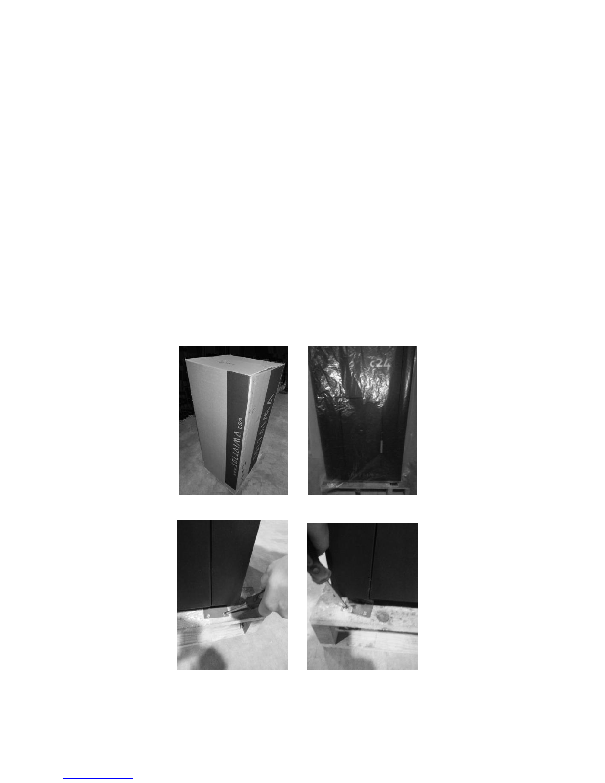
1.1. Unpacking the boiler
When unpacking the unit, please refer to the illustrations below. First remove the
retractable bag covering the cardboard box (Figure 1-a). Pull the cardboard box out
(Figure 1-b) by lifting it and then remove both the bag covering the boiler and the
styrofoam plates. Finally, unscrew the four pieces securing the unit to the wood pallet
(Figures 1-c and 1-d).
a) b)
c) d)
Figure 1 – Unpacking the boiler

4
2. Safety precautions
Solzaima shall not liable for any damages to the unit caused by failure to comply with
the specified precautions, warnings and operating procedures.
Wile units manufactured by Solzaima are easy to operate, special attention was
given to their components to prevent accidental damages to users and installers.
The units must only be installed by an authorised engineer, who should supply the
client with a relevant statement of conformity and who shall be liable for the final
installation and consequent product good operating conditions.
This unit must be used according to its intended use as specified by the
manufacturer. The manufacturer excludes all contractual or non-contractual
obligations regarding damages to people, animals or property arising from the unit’s
misuse, faulty installation or servicing procedure.
After removing the packaging, verify the contents to check their integrity and
completeness. If the contents of the package do not correspond to the items listed
under 1, contact the sales representative from whom you purchased the unit.
The complete set of parts provided with the unit guarantees its operation and energy
efficiency; these parts should only be replaced with original parts provided by an
authorised technical assistance centre.
The unit must be subject to maintenance at least once a year by the installation
engineer.
This manual is provided with the product. Please keep it close to the unit.
2.1. For your safety, please remember:
The pellet boiler is a biomass heating unit. Be sure to carefully read and
understand the information contained in this book, before handling or operating the
unit;
Make sure the hydraulic circuit is correctly assembled and connected to the water
supply system before turning on the pellet boiler;
The boiler is not intended for use by children or persons with a physical, sensory
or mental handicap, unexperienced or unaware of its proper use, unsupervised or not
instructed concerning the use of the unit;
Do not touch the boiler when barefoot or any part of your body is wet or humid;

5
Do not tamper with any safety or adjustment features of the unit without the
manufacturer's authorisation;
Do not cover or reduce the size of the aeration vents existing near the installation
area;
The pellet boiler needs air circulation for proper combustion, so possible air
tightness of the location or any existing air extraction sources in the room may
prevent the unit’s proper operation;
The existence of aeration vents is a requisite for proper combustion;
Do not leave the packing materials near children;
During the unit's normal operation do not attempt to open the boiler's door;
Avoid direct contact with parts of the unit that overheat during operation;
Check the fume duct for blockages before turning on the unit after a long period
of inactivity;
This pellet boiler is intended for residential use in a protected environment. The
unit might get turned off by any safety systems installed in the household. If this
occurs, contact the technical assistance. Under no circumstances should you disarm
the safety systems;
The pellet boiler is a biomass heating unit equipped with a fume exhaustion
system powered by an electric exhauster. The occurrence of any power failure during
its use may prevent the fume exhaustion thus causing the room to be filled with
smoke. For this reason, you should have a natural fume exhaustion system, like a
chimney, installed;
Solzaima offers you an optional safety system which allows the boiler unit to be
connected to a UPS to allow that during any power failure the fume exhaustion
system will still operate until complete exhaustion of all boiler fumes;
If you intend to use the boiler unit unsupervised or while you are away from
home, you should use the above safety system for total safety during any power
failure;
During operation, NEVER turn off the pellet boiler by unplugging the power cord
from the wall socket. The fume exhaustion system on the pellet boiler is power-
operated so disconnecting the power plug will prevent the exhaustion of combustion
fumes;

6
Before performing any maintenance or assistance to your unit, disconnect it from
the power mains. Before performing any of these operations, allow the unit to cool
down completely (if previously operating);
Never touch the interior of the boiler when connected to the power mains;
For this boiler, the maximum setting for the water temperature that can be
specified by the user (water set-point temperature) is 85°C. If a temperature of 90ºC
is reached, the boiler automatically turns off causing the corresponding alarm to go
off.

7
3. Technical specifications
Features
Boiler
C18 kW
Boiler
C24 kW
Units
Weight
230
232
Kg
Height
1305
1305
mm
Width
667
667
mm
Depth
744
744
mm
Fume discharge pipe diameter
100
100
mm
Reservoir capacity
60
60
kg
Maximum heating capacity
410
523
m³
Maximum overall thermal power (air/hydro)
18
23
kW
Minimum thermal power (air/hydro)
6,5
6,5
kW
Minimum fuel consumption
1,6
1,6
kg/h
Maximum fuel consumption
4,5
5,8
kg/h
Rated electrical current
134
134
W
Electric power at start-up (<10 min.)
434
434
W
Rated voltage
230
230
V
Rated frequency
50
50
Hz
Thermal yield at rated thermal power
89,6
89,3
%
Thermal yield at reduced thermal power
91,8
91,8
%
Combustion gas flow (max.)
19
21
g/s
Combustion gas flow (min.)
10
11
g/s
Max. gas temperature
148
172
ºC
CO emissions at rated thermal power
0,009
0,014
%
CO emissions at reduced thermal power
0,038
0,038
%
Draught in the chimney
12
12
Pa
Boiler's water volume
22
22
L
Fume extractor noise emission
49,1
49,1
dB(A)
Table 1 – Technical specifications
8
The tests were performed using wood pellets with a heating capacity of 4.9 kWh/kg.
The above information was obtained during product homologation tests performed by
independent laboratories accredited for pellet unit tests.
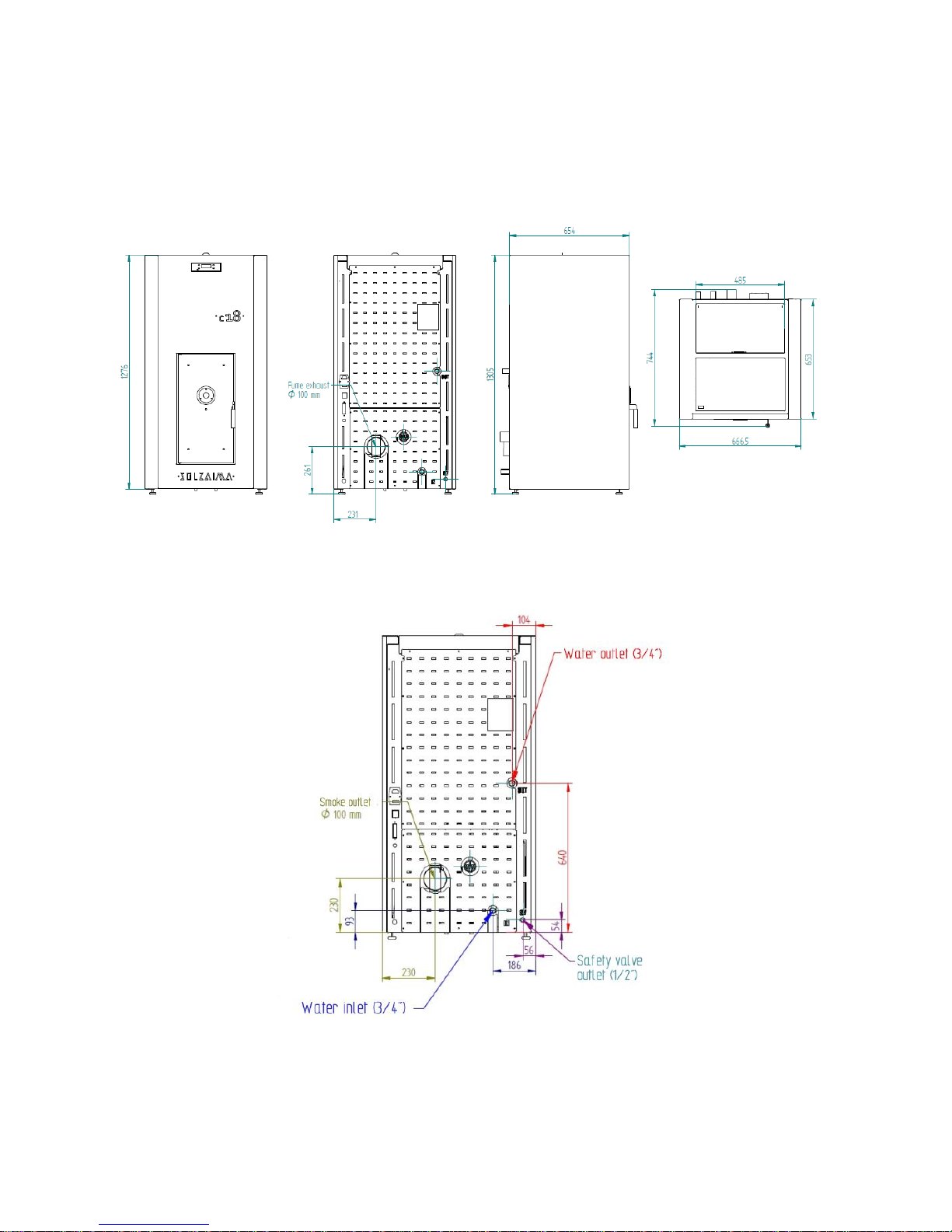
Front Rear Side Top
Figure 2 - Pellet Compact Boiler - Measures
Figure 3 - Pellet compact boiler - Hydraulic connections

9
4. Installing the pellet boiler
Before installing the unit, please perform the following steps:
When receiving the package, inspect the product to check for completeness
and any signs of damage. Any damages or defects should be acknowledged before
the unit is installed;
The boiler has four adjustable feet at the base which allow for an easy setting of
the height when the unit is installed on a non flat surface;
Figure 4 – Adjustable feet
Remove the instruction manual from the package and hand it over to the client;
Connect the combustion gas outlet to the fume exhaustion duct going out of the
building (through a chimney, for instance) using a 100mm-wide piping – check the
diagrams under section 4;
If using a tube for admission of external air for combustion, this tube must have
a maximum horizontal length of 60cm, straight and with no elbows;
Perform the hydraulic system installation (please refer to section 4.5);
Connect the 230 VAC power cable to a grounded wall power socket;
The remote control of the unit includes a programmable thermostat. As an
option, a conventional external programmer may be used (not provided with the
unit) to automatically setup the unit's operating periods.
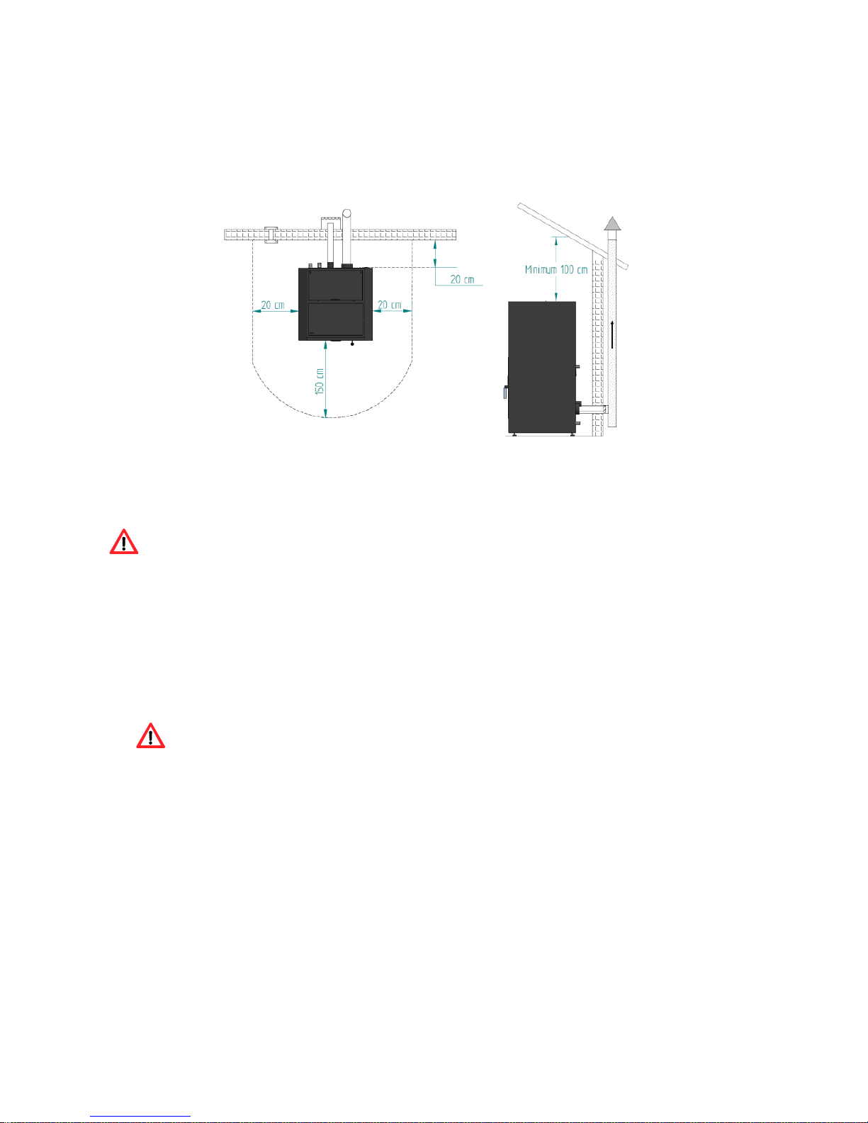
4.1. Installation requirements
Figure 5 specifies the minimum separation distance between the pellet boiler and
particularly flammable surfaces.
10
The top of the boiler must be separated at least 100cm from the ceiling, especially in
rooms with ceilings consisting of flammable materials.
The base supporting the boiler cannot be made of combustible material, so make
sure you always put in place an adequate protection.
a) b)
Figure 5 – Minimum separation distances from all surfaces: a) top view of an installed
unit; b) side view of an installed unit
WARNING!
Keep combustible and flammable materials away from the unit, at a safe distance.
4.2. Installation of ducts and fume exhaust systems:
The gas exhaust pipe must have been designed for this purpose, in compliance
with local requirements and in accordance with any existing applicable regulations.
Important! An inspection T-tube with airtight lid must be attached to the
outlet of the unit’s exhaust pipe to allow for the regular inspection of the system or
release of heavy dust and condensates.
As shown in Figure 5, the assembly of the exhaust pipe must include inspection
couplers to allow access for cleaning and maintenance operations.
Under normal operating conditions, the combustion gas exhaustion should create
a draught of 12 Pa one meter above the chimney neck.
The boiler should make exclusive use of the chimney.
All pipes on the exterior to the installation location must have an internal diameter
of 100mm and double stainless steel insulation.
11
The fume exhaust pipe may generate condensation, so we recommend that
the appropriate systems for collecting condensates should be installed.
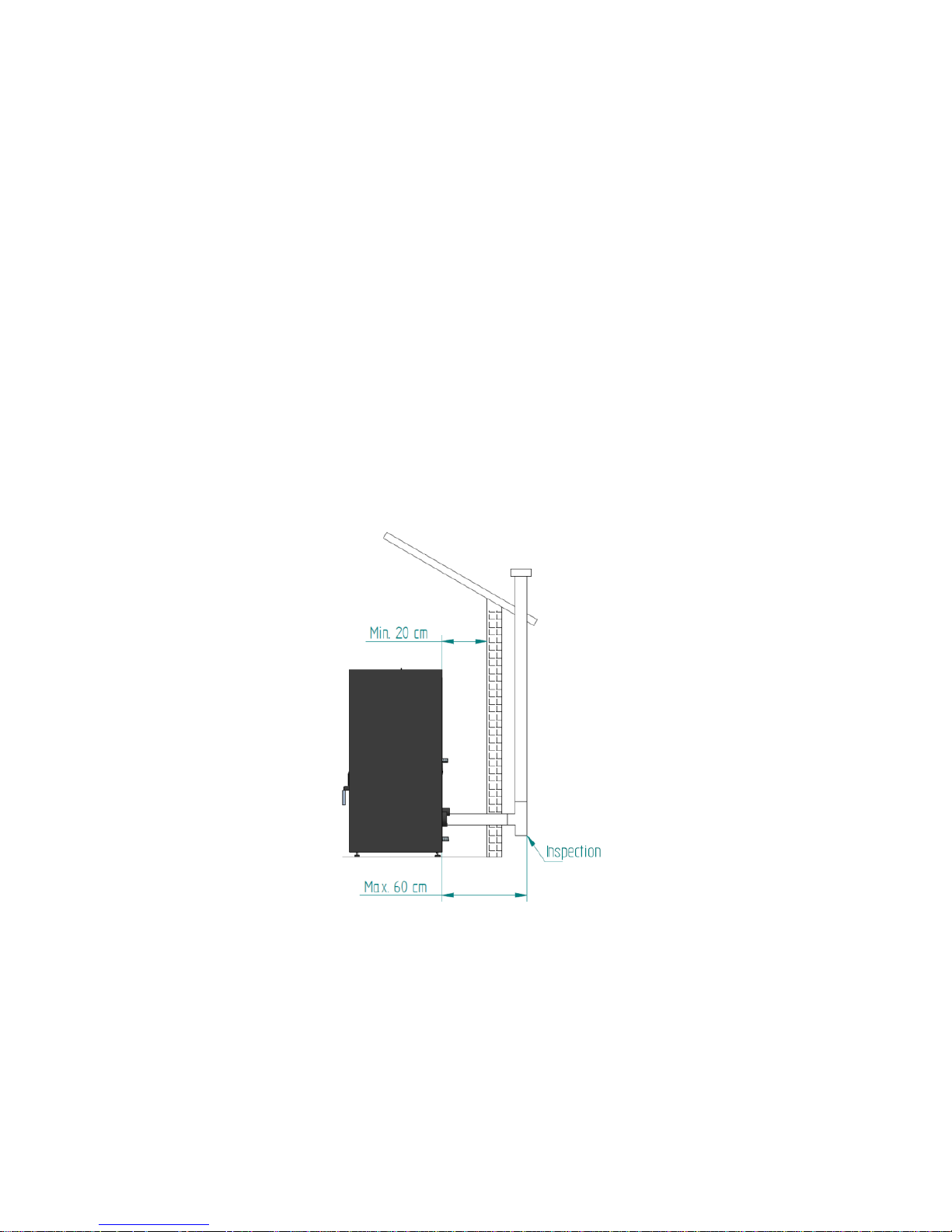
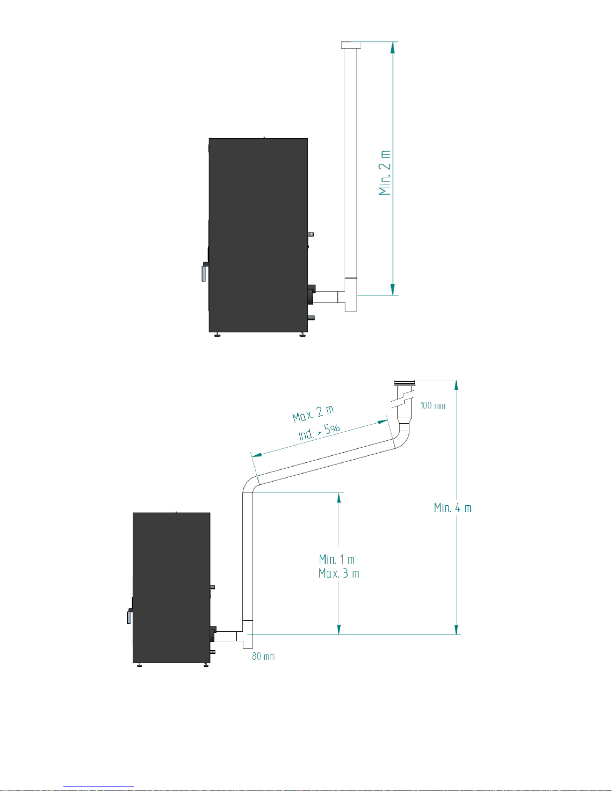
4.3. Installation in the absence of a chimney
The installation of the pellet boiler in the absence of a chimney should be performed
as shown in Figure 6, by directing the fume exhaust pipe (with a minimum inner
diameter of 80mm for the air model and 100mm for the water model) straight
outwards and onto the top of the roof.
Double-wall stainless steel insulated pipes must be used and these pipes must be
properly fastened to avoid condensation.
The installation of an inspection T-tube at the base of the piping must be considered
to allow for the performance of periodic inspections and annual maintenance, as
shown in Figure 6. Figure 7 shows the basic requirements for installing the boiler’s
flue pipe.
Figure 6 – Side view: installation with a chimney with inspection coupler.
12
a)
b)
13
c)
Figure 7 – Examples of standard installations.
Failure to comply with these requirements may prevent the correct operation of
the boiler. Follow all the instructions shown on the diagrams.
Because the boilers operate with the combustion chamber in draught it is an
absolute requirement to install a fume exhaust pipe to allow for the proper extraction
of the combustion gases.
Fume duct materials: The tubing must be made of 0.5mm thick rigid stainless steel,
use with pipe fittings to attach different sections and accessories.
Insulation: The fume ducts must be double-wall and properly insulated to make sure
that fumes do not cool down going outwards, which would cause inadequate
circulation and condensation that may damage the unit.
Out T-tube: Make sure you attach to the boiler output a fitting T-tube.

14
Anti-downdraught terminal: An anti-downdraught terminal must be installed to
avoid the backflow of fumes.
Draught in the chimney: The following figures show three standard diagrams
containing the correct length and diameter specifications. Any other type of
installation that you choose to perform must guarantee a draught of 12 Pa
(0.12mbar) measured at maximum heat and power.
Ventilation: For the boiler’s correct operation it is necessary to have an air inlet
with a minimum section of 100cm2 available at the installation location,
preferably near the rear panel of the unit. The boiler is equipped with a round pipe
( 50mm) that may be connected to the exterior of the house.
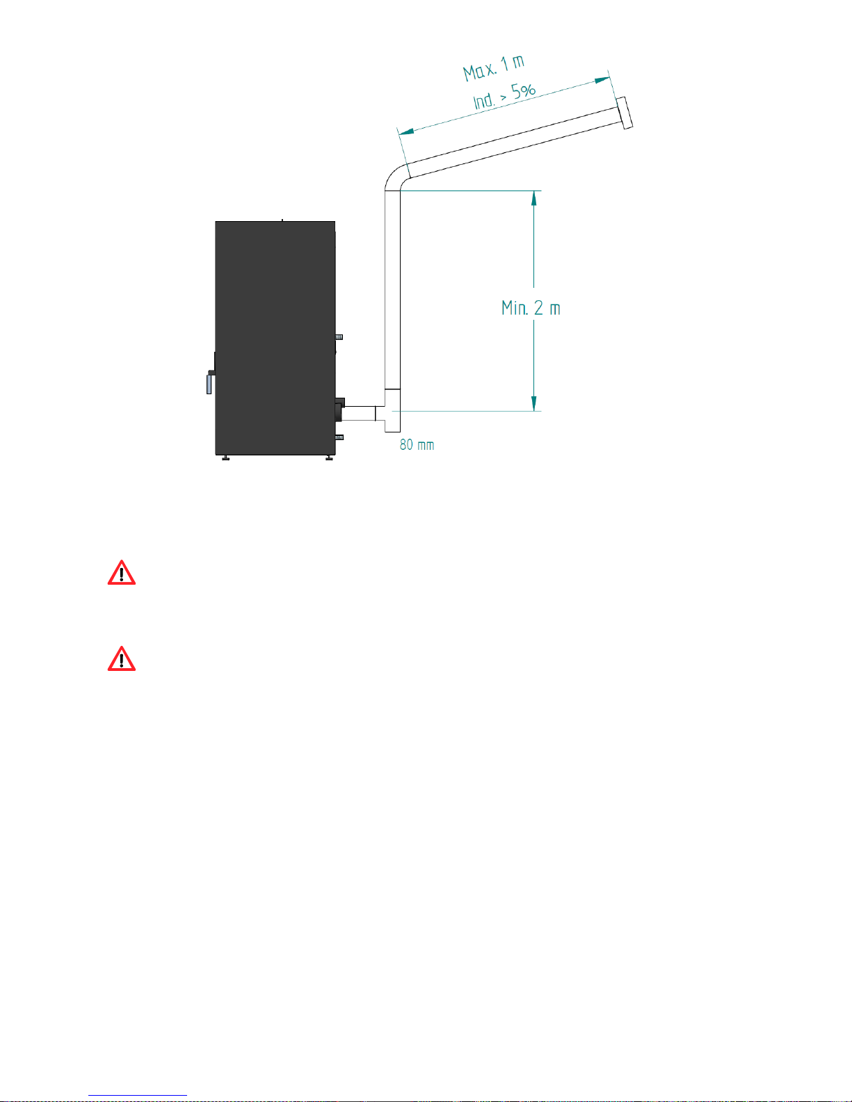
4.4. Installation with a chimney
As shown in Figure 8, the 100mm exhaust pipe of the pellet boiler is installed
directly on to the chimney. If the chimney is too large, we recommend that you attach
an 80mm pipe to the fume outlet.
You should also consider attaching a T-tube to the base of the pipe to allow for
periodic inspection and annual maintenance, as illustrated in Figure 8.
Figure 8 – Side view: installation with chimney with inspection coupler.
We do not recommend that you use the boiler in rough weather conditions that may
seriously impact the draught (particularly with very strong winds).

15
If you do not use the unit for a long time, check it to make sure that the flue pipes are
clear before lighting the fire.
4.5. Hydraulic installation
* Chapter 12 (installation diagrams) contains the optional connection diagrams for
central heating installations, with or without water heating for household use;
* The pellet boiler is equipped with a circulation pump, an expansion vessel (6 litre
volume in the 18kW compact boiler model) or 10 litre volume (in the 24kW compact
boiler model) and a 3 bar safety valve;
* Operating pressure ranges from 1-1.5 bars;
* To empty the unit, attach a T-tube with a tap at the outlet (connected to the
household sewage); the safety valve (3 bar) outlet should also be connected to
the household sewage;
*The heating fluid must consist of water with an anti-rust, non-toxic product added in
the quantity recommended by the manufacturer. If the location where the boiler or the
fluid pipes are installed is likely to freeze, the installation engineer must add to the
circulating fluid the amount of antifreeze product recommended by the manufacturer,
to avoid it to freeze at the estimated minimum temperature.
5. Fuel
The pellet boiler must be operated exclusively with pellets. No other fuel may be
used.
Use only pellets certified by standard EN 14961-2 grade A1, with a 6mm diameter
and a length between 10-30mm.

16
The pellets may have a maximum humidity of 8% their weight. To guarantee a good
combustion, the pellets must maintain these characteristics so they should be stored
in a dry place.
The use of pellets other than those recommended may reduce the efficiency of the
unit and cause deficient combustion.
You should always use certified pellets and must not forget to test a sample
before buying large bulks.
The physical/chemical properties of the pellets (i.e. the calibre, friction, density and
chemical composition) may vary within specific tolerances and according to each
manufacturer. Please note that this may cause alterations to the combustion feed
that would consequently cause the need to use different quantities of pellets.
The boiler allows the quantity of pellets to be adjusted during start-up and at
the different power ranges by ± 25% (refer to section 7.3.6 of the manual – power
and transition settings).
WARNING!
The unit CANNOT be used as an incinerator.
6. Using the pellet boiler
Recommendations
Before starting up the unit, please check the following:
Make sure that the unit is properly connected to the power mains using the
230VAC power cable.
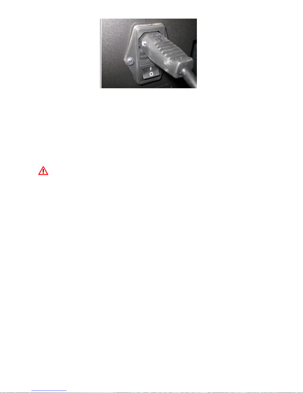
17
Figure 9 – Electric power plug.
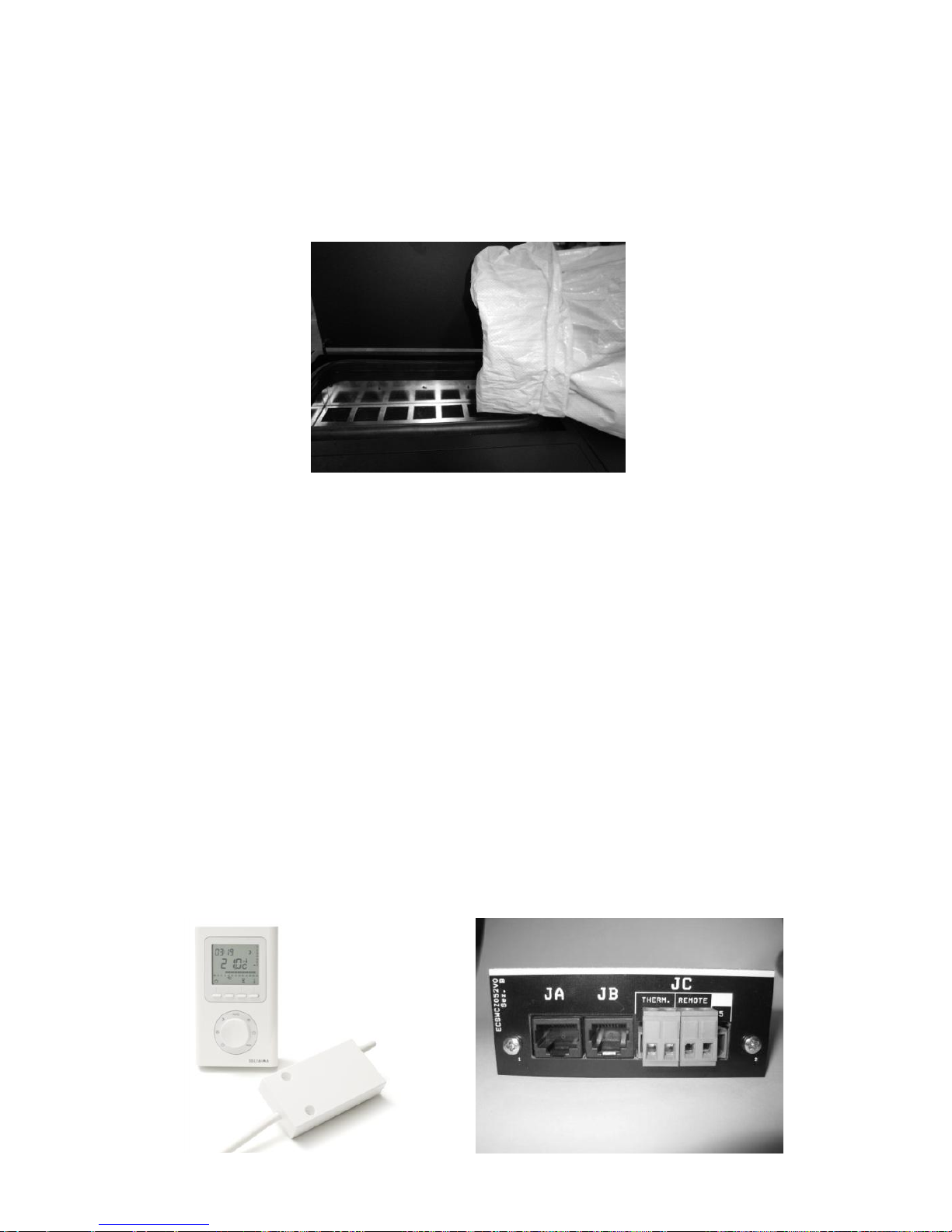
Check to see whether the pellet reservoir is supplied with pellets. Inside the pellet
reservoir is a safety grid to prevent users from reaching the worm screw.
Before each time you light up the boiler, make sure the burner is unobstructed.
The boiler's combustion chamber and door are made of iron painted with high
temperature-resistant paint; this will cause the releasing of fumes during the first
burning sessions due to paint curing.
Make sure the hydraulic circuit has been correctly assembled and that it is connected
to the water supply.
You should check that there is sufficient ventilation in the room where the unit is
installed; otherwise it will not work properly. You should therefore check to see
whether there are other heating air-consuming units in the room (e.g. gas units,
diesel boilers, etc.); these should not be used simultaneously with the unit.
The pellet boilers have a probe for measuring the room temperature. This probe is
attached to the grid on the rear panel (Figure 10). For a good reading of the room
temperature, avoid the contact between the end of the probe and the chassis of the
boiler. You may also attach the probe to the wall beside the unit.

18
Figure 10 - Room temperature prob
7. Control panel
7.1. Display and control panel
Figure 11 – Display and control panel
ON
OFF
OK
MENU
MODE
ESC
MAN
AUT
20.5ºC 16:03
OFF

19
.
Figure 12 – Control keys
7.2. Display information summary
7.2.1. Menu
Menu showing boiler in power "off", the room temperature in ºC and Time.
ON
OFF + OK
MENU
MODE
ESC
-
MAN
AUT
20.5ºC 16:03
OFF
a) Key to toggle between
manual and automatic
mode and exit menus (esc).
b) Key to access menus and
confirmation key (ok).
c) Key to start/stop the
unit and reset error
messages.
d) Key to scroll the menus to
the left, to increase and
reduce the fan flow and
increase or reduce the setpoint temperature.
e) Key to scroll menus to the
right to increase and reduce
the unit's power.

20
“Auto” mode: in this mode, the unit will be turned on at maximum power until
reaching a temperature of 1ºC above the selected temperature (set point
temperature). Upon reaching the set temperature, the unit toggles to the minimum
operating power.
The set-point temperature can be set between 5 and 35ºC by pressing the "-" key.
The "+" key allows the user to set the ventilation speed between 1-5 or to automatic
mode.
7.2.2. Water temperature
Press the Menu key twice to set the water temperature; the “Temp. Agua” (Water
temp.) appears on the display. Press Set to display the “T. Aquecimento” (Heating
Temperature) menu.
Heating temperature
To set the desired heating temperature press “set”. The display starts to flash.
Press the “+” or “-“ key to select the desired temperature and then “ok” to confirm.
Press the "+" key to go to the "Temperatura de sanitários" (Bathroom Temperature)
menu.
Bathroom temperature (this mode is disabled)
ON
OFF
+
OK
MENU
MODE
ESC
-
MAN
AUT
esc Set
< Temp. Água >
ON
OFF + OK
MENU
MODE
ESC
-
MAN
AUT
esc 85ºC Set
< T. Aquecimento >

21
7.2.3. Date/Time
To set the date and time: press the Menu key twice; "Dia e Hora" (Date and Time)
appears on the display. Press "set" to see the "Hora" (Time) menu.
Time
To set the time press “set”. The display starts to flash. Press the “+” or “-” key to
select the desired time and then “ok” to confirm. Press the "+" key to go to the
"Minutos" (Minutes) menu.
Minutes
To set the minutes press “set”. The display starts to flash. Press the “+” or “-” key to
select the desired minutes and then “ok” to confirm. Press the "+" key to go to the
"Dia" (Day) menu.
ON
OFF + OK
MENU
MODE
ESC
-
MAN
AUT
esc Set
< Data e Hora >
ON
OFF + OK
MENU
MODE
ESC
-
MAN
AUT
esc 16 Set
< Hora >
ON
OFF + OK
MENU
MODE
ESC
-
MAN
AUT
esc 18 Set
< Minutos >

22
Day
To set the day of the week press “set”. The display starts to flash. Press the “+” or “-”
key to select the desired day and then “ok” to confirm. Press the "+" key to go to the
"Dia Num." (Day Number) menu.
Day of the month
To set the day of the month press “set”. The display starts to flash. Press the “+” or
“-” key to select the desired day and then “ok” to confirm. Press the "+" key to go to
the "Mês" (Month) menu.
Month
To set the month press “set”. The display starts to flash. Press the “+” or “-” key to
select the desired month and then “ok” to confirm. Press the "+" key to go to the
"Ano" (Year) menu.
Year
To set the year press “set”. The display starts to flash. Press the “+” or “-” key to
select the desired year and then “ok” to confirm. Press "esc" to return to the "Dia e
ON
OFF + OK
MENU
MODE
ESC
-
MAN
AUT
esc 2a Set
< Dia >
ON
OFF + OK
MENU
MODE
ESC
-
MAN
AUT
esc 30 Set
< Dia Num. >
ON
OFF + OK
MENU
MODE
ESC
-
MAN
AUT
esc 4 Set
< Mês >

23
Hora" (Date and Time) menu then "+" scroll to the next menu. The Crono (Timer)
menu appears.
7.2.4. Timer
The boiler is equipped with a timer that allows the unit to be turned on or off at a
specific time.
Activation
To activate the timer press “set”. The "Habilitação" (Activation) menu appears. The
timer may only be activated after the configurations have been set, as shown below.
To activate the timer mode press “set”. The display starts to flash. Press the “+” or
“-” key to select "On" or "Off" and then “ok” to confirm. Press the "+" key to go to the
"Reiniciado" (Reset) menu.
This menu allows you to delete any programme settings. To do this, press "set". The
"Confirmar?" (Confirm?) prompt appears. Press "set" again to confirm that you want
to delete the settings or "esc" to exit.
ON
OFF + OK
MENU
MODE
ESC
-
MAN
AUT
esc 2012 Set
< Ano >
ON
OFF + OK
MENU
MODE
ESC
-
MAN
AUT
esc Set
< Crono >
ON
OFF + OK
MENU
MODE
ESC
-
MAN
AUT
esc Off Set
< Habilitação >

24
The unit's programmer lets you choose from 6 different programmes for each day of
the week.
To set up programmes “P1” to “P6”, select the desired programme using the “-”
and “+” keys, and press “set” to select. The “P1 Habilitação” (Activation) menu
appears.
Press "set" again and, when the display starts to flash, press "+" or "-" to select "On"
or "Off". Press "ok" to confirm the selection. Press the "+" key to go to the "P1 A.
Inicio" (P1 A. Start) menu.
To set the starting time for Programme 1, press “set”. The display starts to flash.
Press the “+” or “-” key to select the desired time and then “ok” to confirm. Press the
"+" key to go to the "P1 H. Stop" (P1 Time Stop) menu.
ON
OFF + OK
MENU
MODE
ESC
-
MAN
AUT
esc Set
< Reiniciado >
ON
OFF + OK
MENU
MODE
ESC
-
MAN
AUT
esc Set
< Prog. 1 >
ON
OFF + OK
MENU
MODE
ESC
-
MAN
AUT
esc On Set
<P1 Habilita >
ON
OFF + OK
MENU
MODE
ESC
-
MAN
AUT
esc 6:15 Set
<P1 H. Inicio >

25
To set the stopping time for Programme 1, press “set”. The display starts to flash.
Press the “+” or “-” key to select the desired time and then “ok” to confirm. Press the
"+" key to go to the "P1 Temp. Ar" (P1 Air Temp) menu.
To set the set point room temperature for Programme P1, press “set”. The display
starts to flash. Press the “+” or “-” key to select the desired temperature and then “ok”
to confirm. Press the "+" key to go to the "P1 Temp. Água" (P1 Water Temp) menu.
To set the water set point temperature (only for the back boiler model) for
Programme P1, press “set”. The display starts to flash. Press the “+” or “-“ key to
select the desired temperature and then “ok” to confirm.
Press the "+" key to go to the "P1 Fire" menu.
To set the operating power (1 to 5) for Programme P1, press “set”. The display
starts to flash. Press the “+” or “-“ key to select the desired power and then “ok” to
confirm. Press the "+" key to go to the "P1 Dia" (P1 Day) menu.
ON
OFF + OK
MENU
MODE
ESC
-
MAN
AUT
esc 20:15 Set
<P1 H. Stop >
ON
OFF + OK
MENU
MODE
ESC
-
MAN
AUT
esc 18ºC Set
<P1 Temp. Ar >
ON
OFF + OK
MENU
MODE
ESC
-
MAN
AUT
esc 35ºC Set
< P1 Temp. Água >

26
To select the days of the week that you want the P1 Programme to run, press "set"
and then select the day of the week using the “-” and “+” keys. Press "set". The
display starts to flash. Select "On" or "Off" using the "-" and "+" keys. Press "ok" to
confirm the selection. Press the "esc" key to go to the "P1 Dia" (P1 Day) menu. Press
"esc" twice and then "+" to go to the "Configurações" (Configuration) menu.
Repeat the above steps for programmes P2 to P6.
Note: After setting up the programmes, please remember to activate them on
the "Habilitações" (Activation) menu.
7.2.5. Sleep
The "Sleep" menu allows you to setup the time you want the boiler to turn off.
Press "set". The display starts to flash. Select the desired time using the "-" and "+"
keys. After choosing the time, press "ok" to confirm. Press "esc" to return to the menu
and then "+" to go to the configuration menu.
ON
OFF + OK
MENU
MODE
ESC
-
MAN
AUT
esc 1 Set
<P1 Fire >
ON
OFF + OK
MENU
MODE
ESC
-
MAN
AUT
esc Set
<P1 Dia >
ON
OFF + OK
MENU
MODE
ESC
-
MAN
AUT
esc OFF Set
SLEEP

27
7.2.6. Configuration menu
To change the boiler's configuration setup press “set”. The “Língua” (Language)
menu appears.
Language
To select the language, press “set”. Using the “+” or “-” keys, select the desired
language (Pt – Portuguese; Nl – Dutch; Gr – Greek; It – Italian; En – English; Fr –
French; Es – Spanish; De – German). Press "ok" to confirm.
Press the "+" key to go to the "eco" menu.
Eco mode
If the boiler is equipped with a thermostat that operates exclusively based on the
temperature, the "eco mode" can be enabled to reduce the fuel consumption. In this
mode, the boiler operates at a set point temperature. The boiler always operates at
maximum operating power until it reaches a temperature of 33.8ºF (1ºC) above the
ON
OFF + OK
MENU
MODE
ESC
-
MAN
AUT
esc 22:00 Set
SLEEP
ON
OFF + OK
MENU
MODE
ESC
-
MAN
AUT
esc Set
< Configurações >
ON
OFF + OK
MENU
MODE
ESC
-
MAN
AUT
esc Pt Set
< Lingua >

28
set point temperature. Upon reaching this temperature, the unit starts operating at
minimum operating power for a preset time period. After this time has elapsed, the
unit turns off. It remains off for another preset period of time. When the measured
room temperature drops to a preset value, the boiler turns on again at the maximum
operating power.
This operation is only available in automatic mode.
To activate the eco mode, press "set". The display starts to flash. Select "On" or "Off"
using the "-" and "+" keys. Press "set" to confirm the selection.
Press "esc" to return to the previous menu and "+" to go to the "Iluminação" (Light)
menu.
Light
To select ‘ecrã iluminado’ (lit screen), press “set”. The display starts to flash. Press
the "+" or "-" key to select the time period during at which you want the screen to be
light up, or choose "On" to keep the light permanently on. Press "ok" to confirm the
selection. Press the "+" key to go to the "Tons" (Tones) menu.
Tones
To activate the key tone, press "set". The display starts to flash. Press the "+" or "-"
key to select "On" or "Off". Press "ok" to confirm. Press the "+" key to go to the
"ºC/ºF" menu.
ON
OFF + OK
MENU
MODE
ESC
-
MAN
AUT
esc Off Set
< Eco >
ON
OFF + OK
MENU
MODE
ESC
-
MAN
AUT
esc On Set
< Iluminação >

29
Temperature scale (ºC/ºF)
To select ºC / ºF, press “set”. The display starts to flash. Press the “+” or “-” key to
select “ºC”, “ºF” or “Auto”, and then “ok” to confirm. Press the "+" key to go to the
"Receita Pellet" (Pellet Qty) menu.
Pellet quantity
Press "set" to show the "Actuações transitórias" (Temporary settings) menu.
- Temporary settings
This feature allows you to increase or decrease by 25% the amount of pellets at
start-up. Press "set". The display starts to flash. Press "+" or "-" to increase or
decrease (-5 to +5), as required. Each unit must be multiplied by 5 to obtain the
ON
OFF + OK
MENU
MODE
ESC
-
MAN
AUT
esc On Set
< Tons >
ON
OFF + OK
MENU
MODE
ESC
-
MAN
AUT
esc Auto Set
< ºC / ºF >
ON
OFF + OK
MENU
MODE
ESC
-
MAN
AUT
esc Set
< Receita Pellet >

30
correct percentage. Press "ok" to confirm the selection. Press the "+" key to go to the
"Actuações de Potência" (Power settings) menu.
Power settings
This feature allows you to increase or decrease by 25% the amount of pellets at each
power level. Press "set". The display starts to flash. Press "+" or "-" to increase or
decrease the setting (-5 to +5), as required. Each unit must be multiplied by 5 to
obtain the correct percentage. Press "ok" to confirm the selection. Press "esc" to
return to the "Receita de pellets" (Pellet Qty) menu and "+" to go to the "Termostato"
(Thermostat) menu.
Thermostat
This feature allows you to enable or disable the room temperature thermostat.
Press “set”. The display starts to flash. Press the “+” or “-” key to select "On" or "Off"
and then “ok” to confirm. Press the "+" key to go to the "Carga Pellet" (Pellet loading)
menu.
ON
OFF + OK
MENU
MODE
ESC
-
MAN
AUT
esc 0 Set
< tuações Transi >
ON
OFF + OK
MENU
MODE
ESC
-
MAN
AUT
esc 0 Set
< Potência >
ON
OFF + OK
MENU
MODE
ESC
-
MAN
AUT
esc Off Set
< Termostato >

31
Pellet loading
This feature allows you to enable the worm drive to fill the channel when it is empty
to ensure lighting of the unit. Press "set"; the "ok" option appears. Press "ok" to
activate the drive (the "habilitada" (Activated) message appears) and "esc" to stop it.
Press the "+" key to go to the "Limpeza" (Cleaning) menu.
Cleaning
This feature allows you to clean the burning basket manually. Press "set"; the "ok"
message appears. Press "ok" to start the cleaning; the "Habilitada" (Activated)
message appears. When you wish to stop, press "ok". Press the "+" key to go to the
"Técnico" (Technical) menu.
The technical menu is not available to the end user since it only includes factory
settings that must never be changed.
7.2.7. User Info
This menu contains some user information regarding the boiler. Press "set"; the
"Código de Ficha" (File Code) menu appears. Display software/firmware code Press
the "+" key to go to the "Horas Funcionamento" (Operating Hours) menu.
ON
OFF + OK
MENU
MODE
ESC
-
MAN
AUT
esc Set
< Carga Pellet >
ON
OFF + OK
MENU
MODE
ESC
-
MAN
AUT
esc Set
< Limpeza >

32
This menu shows the total operation hours of the boiler so far.
Fume exhaust operating speed (rotation per minute).
Airflow measured by the air probe.
Fume temperature.
ON
OFF + OK
MENU
MODE
ESC
-
MAN
AUT
esc Set
< Info Usuario >
ON
OFF + OK
MENU
MODE
ESC
-
MAN
AUT
esc 500308
< Código Display >
ON
OFF + OK
MENU
MODE
ESC
-
MAN
AUT
esc 144
< de Funcioname >
ON
OFF
+
OK
MENU
MODE
ESC
-
MAN
AUT
esc 49 rpm
< Expulsor Fumos >
ON
OFF
+
OK
MENU
MODE
ESC
-
MAN
AUT
esc 40 lpm
< xo de Ar Medid >

33
Worm drive rotation time ("On").
Ventilation power level.
Hydraulic circuit pressure.
ON
OFF
+
OK
MENU
MODE
ESC
-
MAN
AUT
esc 18ºC
< emperatura Fum >
ON
OFF + OK
MENU
MODE
ESC
-
MAN
AUT
esc 0.00s
< Tempo Cóclea >
ON
OFF
+
OK
MENU
MODE
ESC
-
MAN
AUT
esc 35
< Atuação Fan1 >
ON
OFF
+
OK
MENU
MODE
ESC
-
MAN
AUT
esc 1.5bar
< Pressão Água >

34
8. Starting-up the unit
To start operating the pellet boiler, press the start/stop button for 3sec. The display
should indicate "Acendimento" (Lighting) until completion of this phase.
The pellets are fed through the supply channel and into the burning basket
(combustion chamber), where they will be ignited using a heat resistor. This process
may take between 5-10 minutes, depending on whether the worm screw used to
push through the pellets has been previously filled with fuel or is empty. Upon
completion of the ignition phase, the word "On" should appear on the display. The
heating power can be adjusted at any time by pressing the power selection button for
approximately 1 sec. Users can choose between five preset power levels.
The selected power level is shown on the display. The initial power level at each
start-up will be the power level set before the last stop.
8.1. Stopping the unit
The stop sequence of the unit is started by pressing the start/stop key for 3sec.
The display shows the message “desactivação" (Stopping) until the completion of
this phase. The exhaust system remains active until the fume temperature reaches
104ºF (40ºC), to ensure the full burn of all the material.
8.2. Turning off the unit
The unit should only be disconnected after full stop of the operation. Make sure the
display shows the 'Off' sign. Make sure that the display indicates “Off”. If necessary,
disconnect the power cable from the mains.

35
8.3. Instructions for removing the side covers
8.3.1. Removing the side covers
Lift the cover and pull it up and forward, detaching it from the top and front slots. To
reassemble, perform the steps above in reverse order.
Figure 13 – Removing the side covers
8.3.2. Pellet reservoir lid
Open the pellet reservoir by sliding the latch (Figure 14 a) and lifting up the lid
(Figure 14 b).
a) b)
Figure 14 – Opening the lid
36
8.4. Filling the pellet reservoir
1 - Open the pellet reservoir lid at the top of the unit, as shown in Figure 14 b.
2 – Fill the reservoir with pellets, as shown in Figure 15.
Figure 15 – Filling the pellet reservoir
3 - Turn on the unit and close the lid, pressing it down until the latch snaps into place
as shown in Figure 14-a.
8.5. Installing and operating with a remote control
(programmable thermostat) – not supplied with boiler
units
The pellet boiler units are provided from factory with a display and control panel.
Alternatively, you can operate the boiler using a generic remote control unit
(programmable thermostat). Note: Usually, the remote control is supplied with a
user’s manual. To use the remote control, you must install an interface (Figure 16–b).

37
a) b)
Figure 16 – Remote control (programmable thermostat) and connection interface – not included.
If you want to use a wireless remote control, you need to connect the two wires as
shown in the following figure:
a) b)
Figure 17– Connecting a wireless remote control
If you want to use a wired remote control, you need to connect the black and the
grey wires to the receiver as shown in the following figure.
Figure 18 – Connecting a wired remote control
8.5.1. Instructions to perform the remote control
connections
1 - Turn off the unit’s power switch, remove the right side panel of the pellet boiler.
2 – Disconnect the terminator plugs from block phase (F) and neutral (N).
Colour codes:
CN – grey
N – black
C – brown
A – blue

38
a)
3 – Rivet the terminals of the 220V wire that powers the transmitter.
b) c)
4 – Connect the wires to the ON/OFF connector contact (Figure 19 d). Direct the
wires through the cable holder to the interior of the boiler (Figure 19 e).
d) e)
5 – Connect the external remote control plug (On/Off contact) in the "remote" position
(Figure 19 g).

39
f) g)
Figure 19 – Installing the programmable thermostat

40
9. Installing the safety option – UPS Kit
a) b)
Figure 20 – a) example of UPS (not included in the kit); b) UPS kit components
To connect the UPS connection kit, proceed as shown in the figures below.
First, remove the side cover to access the electronic plate (Figure 21 a). Then, attach
the UPS electronic module at the side of the boiler's electronic plate, connecting the
wires to the plate (Figure 21 b and c).
Then remove the plate fixed with micro joints from the back of the unit (Figure 21 d)
and attach the plug to connect the UPS (Figure 21 e). Finally, make the required
electrical connections (Figure 21 g).
Never connect the UPS electronic module with the power of the unit turned on.
a)

41
b) c)
d) e)
f) g)
Figure 21 – Installing the UPS kit
10. Maintenance
The Solzaima pellet boiler requires careful maintenance. The major concern is to
clean the ashes from the pellet burning area at regular intervals. This procedure can
42
be easily done using a common household vacuum cleaner. The cleaning operation
should performed after each burn of approximately 66lbs (60kg) of pellets.
Note: However, before cleaning, the boiler must be turned off and the unit should be
allowed to cool down to prevent personal damage.
Cleaning the Boiler
The boiler’s maintenance operation includes cleaning the airflow pipes. To do this,
open the lid on the top of the boiler (Figure 22 a) and then rotate (Figure 22 b) and lift
the tubes by the handle (Figure 22 c); repeat this procedure several times to shake
off the dirt accumulated inside the tubes.
a) b)
c)
Figure 22 – Cleaning the turbulators
Finally clean the interior of the boiler using a steel brush to remove the accumulated
dirt (Figure 23).

43
a) b)
Figure 23 – Cleaning the interior of the back boiler
Remove the burning basket (Figure 25 a) and ash tray (Figure 25 b) and vacuum
both pieces. You should also clean the boiler’s interior. To do so, open the lid, as
shown in Figure 26. When the cleaning is done, reassemble all parts performing the
above steps in reverse order and close the unit's door.
a) b)
Figure 24 a) Burning basket; b) Ash tray
Figure 25 – Cleaning the burning basket

44
a) b)
Figure 26 – Cleaning the interior of the boiler
Additional cleaning
For every 1300-1700lbs (600-800kg) of pellets consumed, additional cleaning should
be performed.
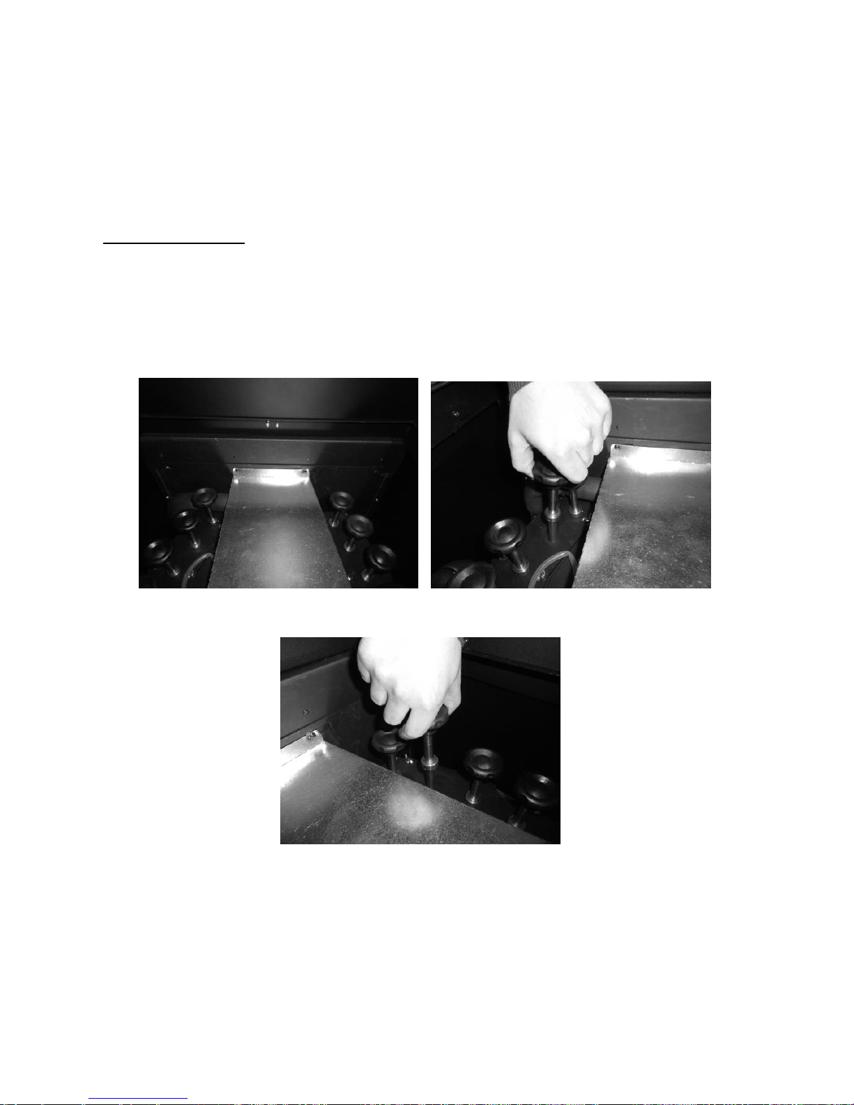
For the back boiler, the procedure includes cleaning the air flow pipes and
turbulators. To do this, open the lid on the top of the unit (Figure 27 a), remove the
galvanized plate and the six wing nuts securing each turbulator set (Figure 27 b and
c). Then pull the turbulators up (Figure 27 d/e). Use a vacuum cleaner to clean this
area (Figure 27 f). Clean the interior of the tubes (Figure 27 g) using a steel brush
(Figure 27 g). The removed turbulators should also be cleaned using a steel brush
(Figure 27 h).
To reassemble the turbulators, perform the steps above in reverse order of the
figures below.
a) b)

45
c) d)
e) f)
g) h)
Figure 27 – Cleaning the air flow pipes and turbulators
If you notice a problem with the fume exhaust, you should clean the exhauster as
shown in Figures 28 and 29 below. By default, we recommend that you execute this
procedure at least once a year.

46
a) b)
Figure 28 – a) Remove the screws; b) Remove the exhauster
Figure 29 – Vacuum the air flow pipes

47
11. Alarm / fault / recommendation list
Table 2 – Alarm list
Important notice: all alarms cause the unit to shut down. The alarm must be
reset and the unit restarted. To reset the unit press the “On/Off” button for 10 seconds
until a beep sounds.
Alarm
Code Cause and troubleshooting
Ignition failure
A01
Maximum time 2400
sec
- the worm drive channel is empty - restart the
unit
- resistance burnt – replace the resistance
- the burning basket has been incorrectly
installed
No flame or no pellets
A02
Temperature under:
104ºF (40°C) (air
model)
109.4ºF (43°C) (water
model)
- Pellet reservoir is empty
Excess heat in the pellet
drum
A03
194ºF (90°C)
- the fan is not working – call for assistance
- faulty thermostat - call for assistance
- machine with faulty ventilation
Excess fume temperature
A04
Over 446ºF (230°C)
(air model);
Over 446ºF (260°C)
(water model)
- the fan is not working or is working at a low
power level - increase the level to the
maximum (if the problem persists, call for
assistance)
- Insufficient extraction
- Excess pellets
Pressure switch alarm
A05
The door is open, lack
of draught or extractor
fault for 60 sec
- close the door and clear the error message
on the faulty pressure regulator
- Obstruction of the exhaust pipe or faulty
extractor
Air mass probe
A06
40 Ipm delta for 3600
sec
- pipes with insufficient extraction or obstructed
pipes
The door is open
A07
Door open for 60
seconds
- close the door - clear the error message
Fume extractor is faulty
A08
Connection failure
- check connection
Fume probe failure
A09
Connection failure
- check connection
Pellet resistance error
A10
Connection failure
- check connection
Worm drive error
A11
Connection failure
- check connection
Pellet level alarm
A15
- check connection
Water pressure outside
operating range
A16
- check connection
Excess water temperature
A18
- check connection

48
- Malfunctioning
Malfunctioning
Maintenance
Air probe failure
Low pellet level
The door is open
Air temperature probe failure
Water temperature probe failure
Water pressure sensor fault
Water pressure close to out of operating range
Table 3 – Malfunction list
Important notice: failures do not cause the machine to shut down.
WARNING!
In case of emergency, shut the unit down following the normal procedure to switch
the unit off.
WARNING!
THE UNIT CAN GET VERY HOT DURING OPERATION SO CARE MUST BE
TAKEN ESPECIALLY REGARDING THE DOOR GLASS AND HANDLE.

49
12. Installation diagrams (for back boilers only -
18kW Compact Boiler and 24 kW Compact
Boiler)
12.1. Central heating installation diagram
Figure 30 – Central heating installation diagram.

50
12.2. Wood and pellet central heating installation
diagram
Figure 31 – Wood and pellet central heating installation diagram

51
12.3. Installation diagram of pellet boiler for central
heating with wall-mounting
Figure 32 – Installation diagram of pellet boiler for central heating with wall-mounting

52
12.4. Installation diagram for central heating and
household water heating using a cylinder thermostat
Figure 33 - Installation diagram for central heating and household water heating using a cylinder
thermostat

53
12.5. Symbols
Figure 34 – Symbols

54
13. Electrical diagram of the pellet boiler
Figure 35 – Electrical diagram

55
14. Performance graphs for the UPSO 15-55
CIAO circulation pump
Figure 36 – Performance graphs for the circulation pump

56
15. Life cycle of a pellet boiler
About 90% of the materials used in the manufacture of these units are recyclable,
thus helping to reduce environmental impact and contributing to the sustainable
development of the Planet. End-of-life units should be returned to authorised waste
processing systems. We advise you to contact your local authorities for instructions.
16. Sustainability
Solzaima designs and manufactures biomass solutions and biomass-fuelled
equipment as a primary energy source. This is our contribution for the sustainability
of our planet – an economically viable and environmentally-friendly alternative,
following environmental best management practices to ensure an efficient carbon
cycle management.
Solzaima makes all efforts to learn and to know the national forest park while
efficiently responding to energy demands, taking permanent care to maintain its
biodiversity and natural wealth that are essential for the quality of life on our Planet.
SOLZAIMA is a member of the Portuguese Sociedade Ponto Verde, which
manages packaging waste from products that the company places on the market, so
you can take the packaging waste from your unit, such as plastic and cardboard, to
your nearest recycling point.
SOLZAIMA is a member of Amb3E, the entity responsible for collecting waste
electrical and electronic equipment (WEEE). Thus, end-of-life units with forced
ventilation systems should be transported to an appropriate WEEE-processing
location. When you disassemble your equipment, you can take its electrical
components to your nearest WEEE collection point.

57
17. Glossary
Ampere (A): SI unit of measurement of electric current
bar: unit of pressure equal to exactly 100,000 Pa. This pressure is very close to
standard atmospheric pressure.
cal (Calorie): equal to the amount of heat required to increase the temperature of one
gram of water by one degree centigrade.
Circuit breaker: Electromechanical device that protects a given electrical appliance.
cm (centimetres): unit of measurement.
CO (carbon monoxide): Lightly flammable, colourless, odourless and very dangerous
gas, due to its toxicity.
CO2 (carbon dioxide): Gas needed by plants for photosynthesis on the one hand, and
emitted into the atmosphere on the other, contributing to the greenhouse effect.
CO emissions: emission of carbon monoxide gas into the atmosphere.
CO Emissions (13% O2): carbon monoxide content corrected to 13% of O
2
.
Combustion: a process that releases energy. Combustion is basically a chemical
reaction that requires three items in order to take place: fuel, oxidant and ignition
temperature.
Creosote: chemical compound created by combustion. This compound is sometimes
deposited on the glass and flue of an insert fire.
Differential switch: protects people and property against grounding failures,
preventing electric shocks and fires.
Energy efficiency: capacity to generate large quantities of heat with the least
amount of energy possible, causing the least environmental impact and reducing the
energy budget.
Fuel: anything that can undergo combustion, in this case wood.
Glass ceramics: highly resistant ceramic material produced through controlled
crystallisation of vitreous materials. Used widely in industrial applications.
Heat-resistant: resistant to high temperatures and thermal shock.
kcal (Kilocalorie): multiple unit of measurement of calories. Equivalent to 1000
calories.
kW (Kilowatt): unit of measurement equal to 1,000 watts.

58
mA (milliampere): unit of measurement of electric current.
mm (millimetres): unit of measurement.
Net heating value: also known as specific combustion heat. It represents the
amount of heat released when a certain amount of fuel is completely burned.
Calorific value is expressed in calories (or kilocalories) per unit of weight of fuel.
Oxidiser: chemical substance that feeds combustion (essentially oxygen) and is
essential for it to take place.
Pa (Pascal): standard IS unit of pressure and tension. This unit is named after Blaise
Pascal, eminent French mathematician, physicist and philosopher.
Performance: expressed as a percentage of “useful energy” that can be extracted
from a given system, taking into account the “total energy” of the fuel used.
Ignition temperature: temperature above which the fuel can enter into combustion.
Plumb: vertically above the installation.
Power output: a manufacturer's recommendation from tests on the equipment with
firewood loads within a reasonable operating range. This power output range will
present different firewood consumptions per hour.
Rated net heating value: heating capacity, i.e. the heat energy the unit transfers
from energy present in the firewood – measured for a standard load of firewood over
a given period of time.
Rated power: Electric power consumed by an energy source. Measured in watts.
W (Watt): IS unit of power.

59
18. Warranty
All SOLZAIMA pellet boilers offer a 2-year (two year) warranty from the date the
invoice is issued. In order for your warranty to be valid, you must keep the invoice or
receipt of purchase during the warranty period.
All electrical resistances have a 6-month warranty.
The warranty applies only to defects in materials or manufacture.
Exclusions:
This warranty does not cover broken glass;
The type of fuel used and how the unit is handled are beyond SOLZAIMA’s control,
so parts in direct contact with the flame are not covered by this warranty;
This warranty does not cover the sealing ring;
The installer bears full responsibility for all problems and/or defects resulting from the
installation process;
Costs incurred from displacement, transport, labour, packaging, disassembly and
down periods of the unit resulting from procedures covered by this warranty are the
responsibility of the purchaser;
Any malfunctioning caused by mechanical or electrical parts not supplied by
SOLZAIMA and which are prohibited under the instructions governing heating
appliances are not covered by this warranty;
Installing the boiler unit near medium/high voltage lines with fluctuations above
230V±5% may damage the unit’s electrical components. Therefore it is advisable for
the unit to be connected to a current stabiliser.
Notice:
The use of a current stabiliser or UPS is generally recommended, to ensure all
electrical components operate properly.
SOLZAIMA disclaims any responsibility for damage caused from using fuel other
than pellets certified by standard EN 14961-2 grade A1.
19. Annexes

60
Operation flow charts
Flow chart 1 – Normal activation
Note (only for the water model): The circulation pump operates on pulse power from
the moment the water temperature reaches 50ºC and continuously from the set-point
temperature.

61
Flow chart 2 - Disconnecting the machine

62
Note (only for the water model): The circulation pump is turned off when the water
temperature reaches below 40ºC.
 Loading...