

Page 1
User Guide
Page 2

Table of Contents
Overview � � � � � � � � � � � � � � � � � � � � � � � � � � � � � � � � � � � � � � � � � � � � � � � � � � � �3
Front panel overview � � � � � � � � � � � � � � � � � � � � � � � � � � � � � � � � � � � � � � � � � � � 4
Rear panel overview � � � � � � � � � � � � � � � � � � � � � � � � � � � � � � � � � � � � � � � � � � �5
How to connect to a DAW (Digital Audio Workstation) � � � � � � � � � � � � � � � � � � � 6
How to silently practice with headphones � � � � � � � � � � � � � � � � � � � � � � � � � � �7
Live set-up with stage volume � � � � � � � � � � � � � � � � � � � � � � � � � � � � � � � � � � � � 8
How to slave an amp � � � � � � � � � � � � � � � � � � � � � � � � � � � � � � � � � � � � � � � � � �9
Impulse Response Section � � � � � � � � � � � � � � � � � � � � � � � � � � � � � � � � � � � � �10
Headphone Section � � � � � � � � � � � � � � � � � � � � � � � � � � � � � � � � � � � � � � � � � � � 11
D�I� Section � � � � � � � � � � � � � � � � � � � � � � � � � � � � � � � � � � � � � � � � � � � � � � � � �12
Managing impulse responses with a computer � � � � � � � � � � � � � � � � � � � � � �13
Impulse responses included with Reactive Load I�R� � � � � � � � � � � � � � � � � �14
Technical Block Diagram � � � � � � � � � � � � � � � � � � � � � � � � � � � � � � � � � � � � � � �15
Technical Specications � � � � � � � � � � � � � � � � � � � � � � � � � � � � � � � � � � � � � � �16
Warranty � � � � � � � � � � � � � � � � � � � � � � � � � � � � � � � � � � � � � � � � � � � � � � � � � � �16
2
Page 3
Thank you for purchasing the Suhr Reactive Load I.R.™
Please take the time to read this User Guide to get the most out of the
Reactive Load I.R. The more you familiarize yourself with the features of this
unit, the more you will enjoy its benets and maximize its potential.
Overview
The new Reactive Load I�R� builds upon the legacy of what is already widely
regarded as the industry standard for accurate speaker cabinet load
replacement: the original Suhr Reactive Load� Reactive Load I�R�
incorporates exciting new features into the groundbreaking design of the
original Reactive Load – making it the ultimate all-in-one solution for
speaker cabinet replacement�
As the name suggests, Reactive Load I�R� adds impulse response
technology to the original Reactive Load, allowing you to quickly and
easily access an array of expertly mic’d speaker cabinets. It comes
preloaded with 16 Suhr speaker cabinet impulse responses captured by
Celestion� Reactive Load I�R� is an open system, so you can load 3rd party
impulse responses via the USB port�
3
Page 4
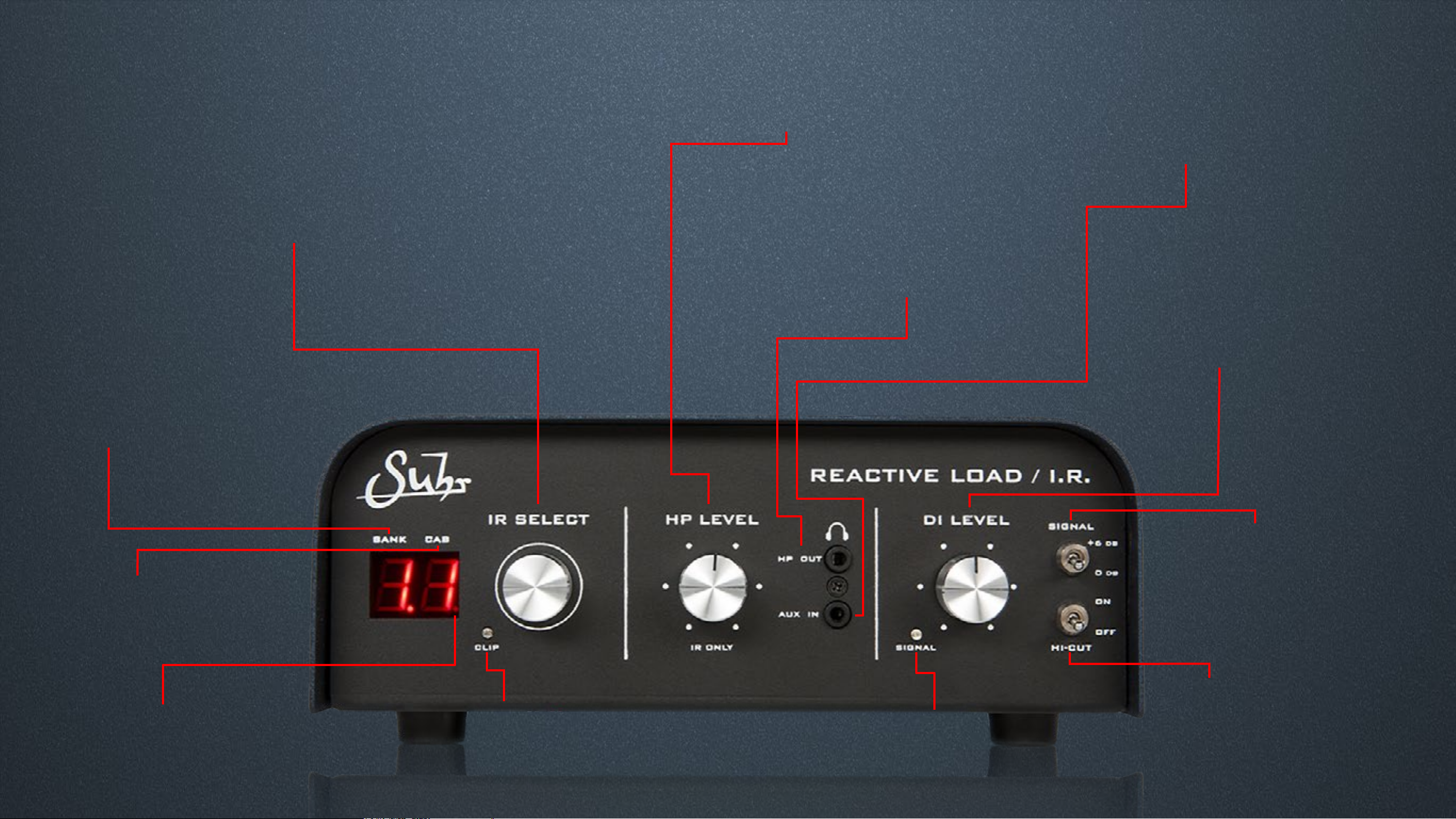
H.P. Level
I.R. Select
Turn to select between 4 banks of 4 Impulse Responses
for a total of 16 different CAB choices
Push and hold to 'lock' your selected I.R.,
this prevents accidentally changing to another I.R.
even when you turn the unit on and off
Turn to adjust volume of
IR output through headphones
H.P. Output
1/8’' Stereo Headphone output
for easy monitoring or practice
Aux Input
1/8’' Stereo Auxiliary Input for connecting
smart-phone or other audio device
D.I. Level
Turn to control volume of
Balanced/Unbalanced Outputs
Bank Number
Displays selected Bank (1-4)
Cab Number
Displays selected Cab
I.R. (1-4)
Signal Boost
Boosts signal 6db, most
useful with low wattage amps
Hi-Cut
I.R. Lock light
Only lights up when I.R. selection
is locked. (see page 10)
Clip light
Only lights up when I.R.
input signal begins clipping
Signal Light
Illuminates when signal
is present
Adjusts impedance curve,
most useful when slaving
an amp
Page 5
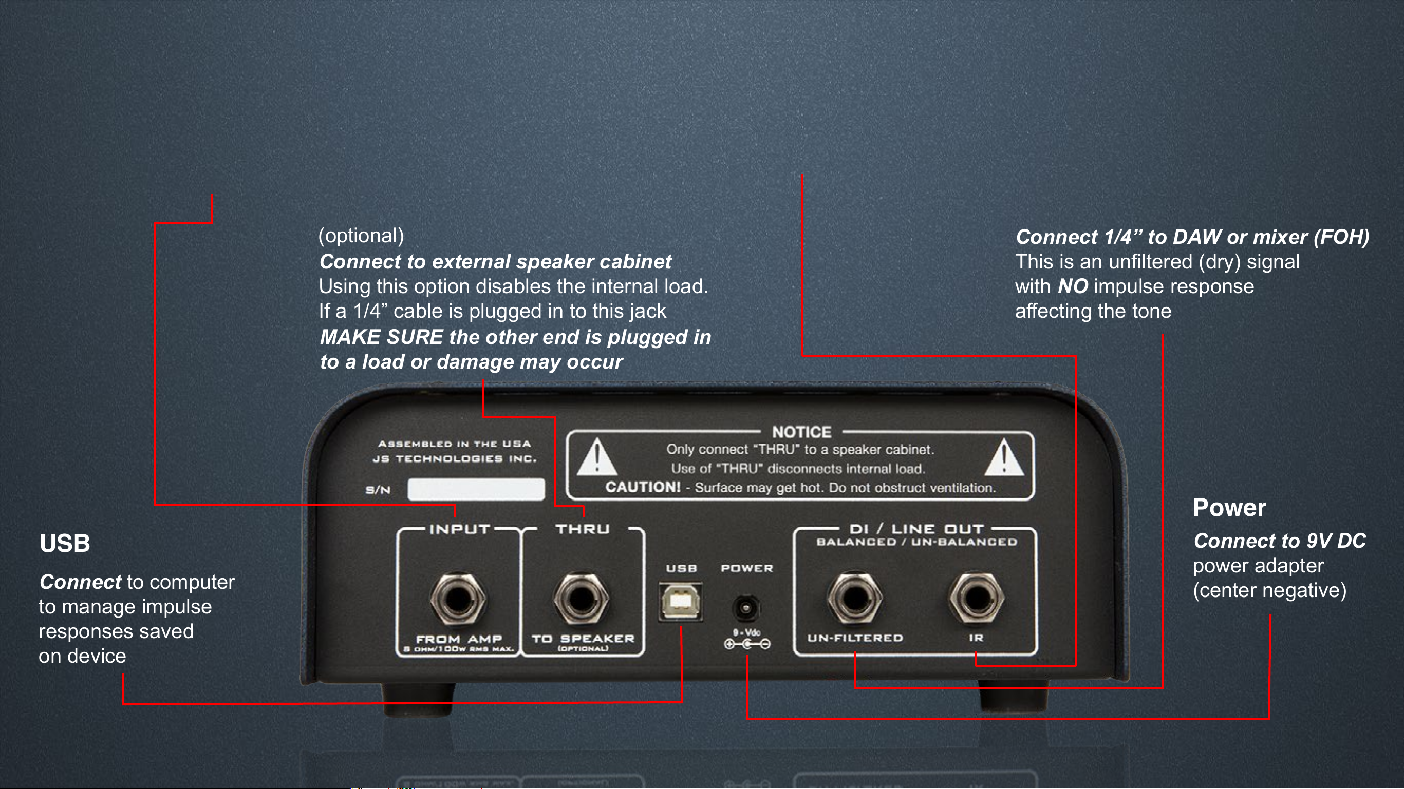
Input (From Amp)
DI/Line Out (I.R.)
Connect 1/4” to DAW or mixer (FOH)
Plug in 1/4” speaker cable from 8 ohms
Speaker Out of amp (Generally 4 ohms is ok,
but consult your amp manufacturer)
Thru (To Speaker)
(optional)
Connect to external speaker cabinet
Using this option disables the internal load.
If a 1/4” cable is plugged in to this jack
MAKE SURE the other end is plugged in
to a load or damage may occur
This signal is ltered through the impulse response,
meaning you will hear the tone with your selected I.R.
DI/Line Out (Un-ltered)
Connect 1/4” to DAW or mixer (FOH)
This is an unltered (dry) signal
with NO impulse response
affecting the tone
USB
Connect to computer
to manage impulse
responses saved
on device
Power
Connect to 9V DC
power adapter
(center negative)
Page 6
Interface
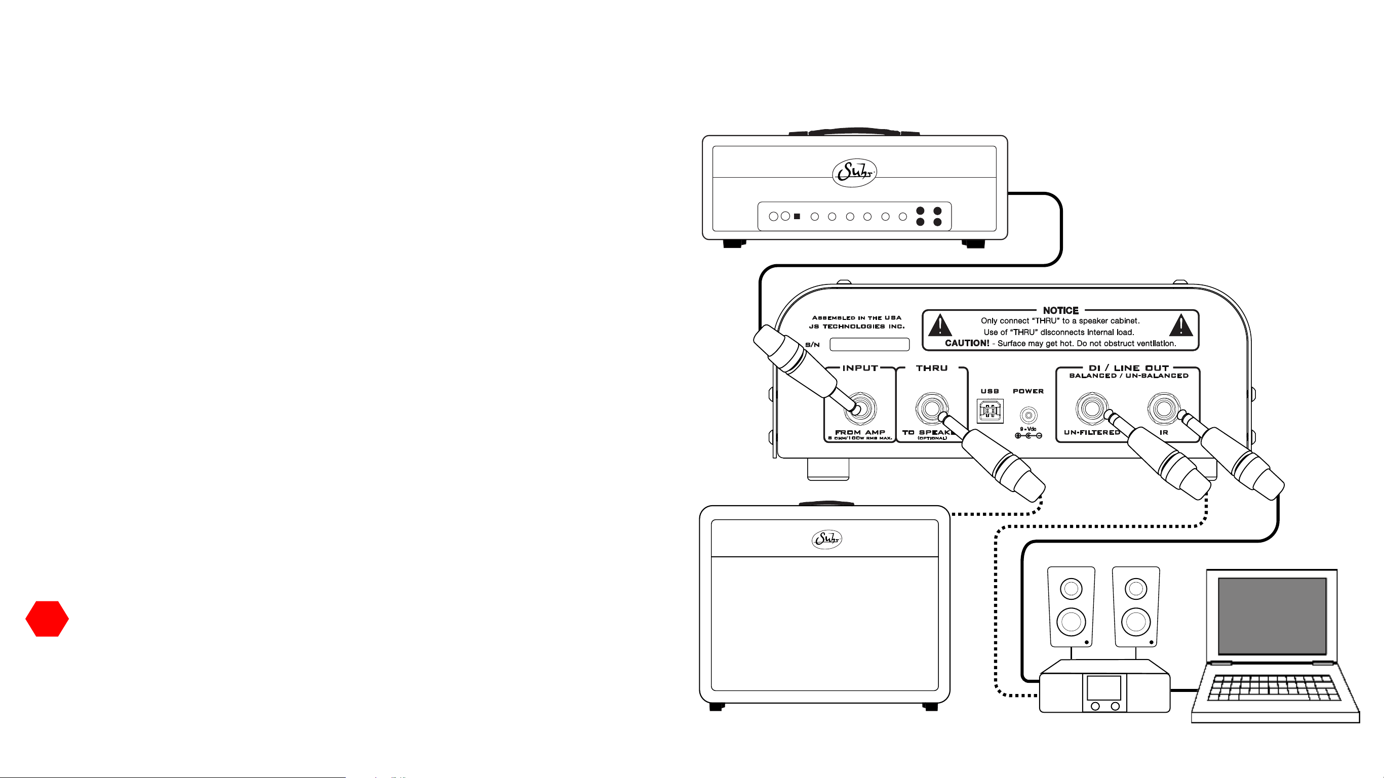
How to connect to a DAW (Digital Audio Workstation)
This guide will show the ways you can connect your Reactive Load I�R� to a
digital audio workstation�
Steps:
1� Plug in the provided 9Vdc power adapter�
2� Connect your amplier's 8Ω speaker out via 1/4" speaker cable to
Reactive Load I.R.'s INPUT – FROM AMP jack�
3� Connect the DI / LINE OUT – IR to record a signal that is affected by the
I.R. lter.
4� Adjust DI LEVEL (D�I� Section in detail, page 12)
5� Turn the IR SELECT knob to pick an I�R�
–Optional connections–
(dotted lines on diagram)
6� Connect the DI / LINE OUT – UN-FILTERED to record a signal that is
NOT affected by the I.R. lter, meaning it is just your amp’s tone (with no
speaker ltration), for later processing in your DAW. If you'd still like to run
a speaker cabinet, connect the THRU – TO SPEAKERS jack using a 1/4"
(Speaker Cable)
(Optional)
(Speaker Cable)
(Optional)
speaker cable to a speaker cabinet�
!!
IMPORTANT NOTE: Using the THRU – TO SPEAKERS output
disconnects the internal load of the Reactive Load I�R� To optimize
performance and avoid damage, match the impedance of your amplier
to the connected speaker cabinet�
NEVER CONNECT THIS OUTPUT TO INSTRUMENT,
MIC OR LINE LEVEL INPUTS.
6
Page 7

How to silently practice with headphones
This section will explain how to use the Reactive Load I�R� to practice
silently through headphones�
Steps:
1� Plug in the provided 9Vdc power adapter�
2� Connect your amplier's 8Ω speaker out via 1/4" speaker cable to
Reactive Load I.R.'s INPUT – FROM AMP jack�
3� Connect HP OUT via 1/8" stereo cable to any headphones�
4� Adjust DI LEVEL (D�I� Section in detail, page 12)
5� Turn the IR SELECT knob to pick an I�R�
Enjoy practicing with your favorite tube amp, quietly with headphones�
-Optional connection-
6� Connect a smart-phone or other audio source via 1/8" stereo cable
(dotted lines on diagram)
(Speaker Cable)
(Optional)
!!
☺☺
IMPORTANT NOTE: The signal from the AUX IN will only be sent
through the HP OUT (headphones), NOT the DI / LINE OUT�
HELPFUL TIP: Use your audio source's on board volume controls to
set the levels you hear through the HP OUT� i�e� if you need to hear
more of your smart-phone, turn up the volume on the device, NOT the
HP LEVEL on the Reactive Load I�R�
7
Page 8

Live set-up with stage volume
This section will explain how to use the Reactive Load I�R� in a live setting
with stage volume from a cab and a D�I� signal (with an I�R�) going to front of
house�
Steps:
1� Plug in the provided 9Vdc power adapter�
2� Connect your amplier's 8Ω speaker out via 1/4" speaker cable to Reactive
Load I.R.'s INPUT – FROM AMP jack�
3� Connect the DI / LINE OUT – I.R. jack to mixer�
4� Connect the THRU – TO SPEAKER jack via 1/4" speaker cable to a
speaker cabinet for stage volume�
5� Adjust DI LEVEL (D�I� Section in detail, page 12)
6� Turn the IR SELECT knob to pick an I�R�
7� (Optional)
Push and Hold for 2 seconds to "lock" your selected I�R� to
keep it from changing inadvertently� (see page 10)
(Speaker Cable)
(Speaker Cable)
!!
IMPORTANT NOTE: Using the THRU – TO SPEAKERS output
disconnects the internal load of the Reactive Load I�R� To optimize
performance and avoid damage, match the impedance of your
amplier to the connected speaker cabinet.
NEVER CONNECT THIS OUTPUT TO INSTRUMENT,
MIC OR LINE LEVEL INPUTS.
8
Page 9

Interface
16Ω 8Ω 8Ω 4Ω 4Ω
SEND RETURN
Effects Loop
How to slave an amp
What is slaving? Slaving is a way of controlling the volume of a high
wattage, non-master volume amp� In addition, slaving can be used to add
effects after the preamp section in amps that lack an effects loop� This
section will explain how to crank a 100-watt amp into the Reactive Load I�R�
and send it to a slave amp for volume control� This allows you to retain the
power distortion of the primary amp, while using a secondary slave amp to
yield lower volumes�
Steps:
1� Plug in the provided 9Vdc power
adapter�
2� Connect your primary amplier's 8Ω
speaker out via 1/4" speaker cable to
Reactive Load I.R.'s INPUT – FROM
AMP jack�
3� Plug in the DI / LINE OUT –
UN-FILTERED to the Effects Loop
Return of the slave amp�
(Speaker Cable)
4� Connect the slave amplier's 8Ω
speaker out via 1/4" speaker cable to
your speaker cabinet�
5� (Optional) Use HI-CUT. This works
by altering the impedance curve to
reduce extra high-end that may occur
when slaving to another amp�
(Optional)
9
Page 10

Impulse Response Section
This section will explain in more detail the I�R� capabilities of the
Reactive Load I�R�
Things to know:
1� Turn IR Select knob to select between 4 banks of 4 impulse
responses for a total of 16 different cab choices�
2� Push and Hold for 2 seconds to "lock" your selected I�R�, this will
freeze the number on the display, even when the unit is powered on
and off, protecting you from accidentally changing I�R�s� The LOCK
INDICATOR LED on the 7 segment display will illuminate when your
I�R� selection is "locked"�
3� Push and Hold again for 2 seconds to "unlock" and you can freely
change to another I�R�
4� The CLIP light provides a visual representation of when excess signal
is fed to the IR section, which will cause clipping of the IR output and HP
OUT� If this occurs, reduce the signal by turning down the DI LEVEL�
5� To see a full list of the preloaded impulse responses see page 14�
10
LOCK INDICATOR
Page 11

Headphone Section
This section will explain in more detail the headphones section of the
Reactive Load I�R�
Things to know:
1� Turn HP LEVEL to increase the volume of the impulse response ltered
signal sent to the headphone out, meaning you will only hear the signal
that is affected by the impulse response chosen on the 7 segment display�
2� Connect a smart-phone or other audio source via 1/8" stereo cable
3� The signal from the AUX IN will only be sent through the HP OUT (head-
phones), NOT the DI / LINE OUT�
4� Use your device's on-board volume controls to set the levels you hear
through the HP OUT, i�e� if you need to hear more of your smart-phone,
turn up the volume on the device, NOT the HP LEVEL on the Reactive
Load I�R�
!!
IMPORTANT NOTE: ***Hearing Damage Warning***
Beware of wearing headphones while powering on the Reactive Load
IR. It's possible the voltages upon start-up will create a momentary
popping sound through the headphone out� To avoid this, plug in
headphones after the device is powered on�
11
Page 12

D.I. Section
This section will explain in more detail the D�I� section of the Reactive
Load I�R� The DI LEVEL is used to optimize the amount of
signal the Reactive Load delivers to your device�
Things to know:
1� Adjusting DI LEVEL using CLIP light - While using your loudest
desired amp setting and performance style, turn DI LEVEL knob until
CLIP light illuminates intermittently, then, back off the DI LEVEL knob
until the CLIP light no longer illuminates�
2� SIGNAL BOOST - Increases signal by +6dB passively by altering the
internal padding� This helps with low wattage amps to get a suitable level�
3� HI-CUT - Works by altering the impedance curve to reduce high end�
This is also very useful when slaving to another amp�
!!
IMPORTANT NOTE: It is NORMAL for the Reactive Load I�R� and
amplier to make some physical noise when playing.
The Reactive Load I�R� contains an internal fan which is powered by
your amplier’s speaker output voltage and designed to
maintain the temperature of the Reactive Load I�R�s internal
components� The fan automatically turns on/off based on the amount
of power delivered to the unit’s Input.
12
Page 13

Managing impulse responses with a computer
Steps:
1� Plug in the provided 9Vdc power adapter
2� Connect Reactive Load I�R� to computer via USB cable
3� The Reactive Load I.R. will appear on your computer as "SUHR_RL"
4� Click "SUHR_RL" to nd 4 folders named "Bank_1" - "Bank_4"
5� Each "Bank_x" folder will contain 4 folders named "Cabinet_1"-"Cabinet_4"
these are where you will nd the impulse responses in the form of .WAV les.
!!
IMPORTANT NOTE: Save a backup of the original "SUHR_RL"
folder to a safe place on your computer in case you want to restore
Reactive Load I�R� to factory settings�
HELPFUL TIP: Close mic impulse responses work best� I�R�s greater
☺☺
than 20�5 milliseconds (ms) will be truncated to 20�5 ms�
6� After doing so, you can delete any existing I.R. (.WAV le) and simply drag and
drop any 3rd party impulse response (�WAV, Mono, 24bit, 48kHz) in to its place�
Use only one I.R. le (.WAV) per cabinet folder.
!!
IMPORTANT NOTE: After making ANY changes to the I�R�s loaded on the
device, use these steps to nish uploading your I.R.s to the device.
7� Your Reactive Load I.R. now is lled with your own I.R.s
- Eject (unmount) "SUHR_RL" from your computer�
If "SUHR_RL" reappears on computer after ejecting, it IS safe to
disconnect, as long as no les are transferring at the time.
- Disconnect USB from the Reactive Load I�R� to your computer�
Disconnecting the USB will nalize the process and update your Reactive
Load IR with the new I�R�s
13
Page 14

Impulse responses included with Reactive Load I.R.
Bank 1:
(1�1) Cab 1 : Suhr G12M Greenback 4x12 C SM57 Balanced Celestion
(1�2) Cab 2 : Suhr G12M Greenback 4x12 C Hi-Gn 121+57 Celestion
(1�3) Cab 3 : Suhr G12M Greenback 4x12 C SM57 Fat Celestion
(1�4) Cab 4 : Suhr G12M Greenback 4x12 C Lo-Gn 421+121 Celestion
Bank 2:
(2�1) Cab 1 : Suhr V30 4x12 C SM57 Balanced Celestion
(2�2) Cab 2 : Suhr V30 4x12 C Hi-Gn 121+57 Celestion
(2�3) Cab 3 : Suhr V30 4x12 C SM57 Fat Celestion
(2�4) Cab 4 : Suhr V30 4x12 C Lo-Gn 421+121 Celestion
Bank 3:
(3�1) Cab 1 : Suhr PT G12-75H Creamback 2x12 C SM57 Fat Celestion
(3�2) Cab 2 : Suhr PT G12-75H Creamback 2x12 C Hi-Gn 121+57 Celestion
(3�3) Cab 3 : Suhr Hedgehog G12-65 2x12 O SM57 Fat Celestion
(3�4) Cab 4 : Suhr Hedgehog G12-65 2x12 O Hi-Gn 121+57 Celestion
Bank 4:
(4�1) Cab 1 : Suhr Badger V30 1x12 C SM57 Balanced Celestion
(4�2) Cab 2 : Suhr Badger V30 1x12 C Hi-Gn 121+57 Celestion
(4�3) Cab 3 : Suhr Bella V-Type 1x12 O SM57 Dark Celestion
(4�4) Cab 4 : Suhr Bella V-Type 1x12 O Hi-Gn 121+57 Celestion
14
Page 15

AMP IN
Technical Block Diagram
AMP THRU
REACTIVE
LOAD
DI LEVEL
BALANCED/UNBALANCED
OUT
UNFILTERED
BALANCED/UNBALANCED
OUT
IR DSP
IR
HIGH CUT
AUX IN (STEREO)
SIGNAL LED
SIGNAL LEVEL
CLIP LED
IR OUTPUT
HEADPHONE LEVEL
HEADPHONE OUTPUT
MIXER
IR SELECT
R
L
(STEREO)
15
Page 16

Technical Specications
Warranty
Impedance: 8Ω
Balanced Line Output Impedance: 600Ω (Maximum)
Unbalanced Line Output Impedance: 600Ω (Maximum)
Maximum recommended input power: 150 Watts RMS
I.R. Format: .WAV, Mono, 24bit, 48kHz, 20.5 ms
(I.R.s greater than 20.5 ms will be truncated to 20.5 ms)
I.R. Output Latency: 1.2 milliseconds
Power Connector: 9Vdc, center negative, 2.1mm x 5.5mm
Operating Voltage: 9Vdc
JS Technologies, Inc� (JST) warrants for lifetime from date of purchase by the
initial retail purchaser that this product shall be free from defects in workman-
ship. Electronic components such as capacitors, resistors, lters, transformers,
jacks, and pots are covered for 5 years� Any parts determined defective by JST
within the ve (5) year term shall be repaired or replaced by JST without charge
for parts and labor provided the unit is returned, transportation costs prepaid, to
JS Technologies, Inc�, 601 Crane Street, Unit A, Lake Elsinore, CA 92530, or to
such facility authorized by JST� JST will pay shipping costs to return the unit to
its owner� Defects in workmanship will be determined by JST for limited lifetime
coverage�
This warranty does not cover damage caused by accident, misuse, abuse, neglect, unauthorized or improperly performed repairs, alterations, and/or wear
and tear occasioned by use of the product, and does not include any expense
for inconvenience or loss of use while the product is being repaired or replaced�
JST expressly disclaims any liability for consequential damages arising from the
sale, use, or inability to use the product� Any warranty implied by law, includ-
Maximum Voltage: 12Vdc
Reverse Battery Protection: Yes
Over Voltage Protection: Yes
Current Consumption: <200mA
Dimensions: 8.8" Width x 8.9" Depth x 3.6" Height
Weight: 6.7 lbs.
ROHS Compliant: Yes
*All specications subject to change without prior notice
ing any warranty of merchantability or tness, is expressly limited to the one (5)
year warranty term for the parts on our ampliers and electronic products. The
foregoing statements of warranty are exclusive and in lieu of all other remedies�
Workmanship lifetime warranty is limited strictly to the original retailer purchaser
of the instrument registered with JST within 10 days of purchase from an authorized JST dealer or distributor� JST will pay shipping costs to return the unit to its
owner within the mainland U�S�
The above warranty policy only applies to customers in USA� If you are an international customer, please check with your distributor and the dealer in your
country for warranty matters� Warranty issues must be handled through your
dealer or distributor� If you are an international customer who purchased (or
plan to purchase) from a US dealer, we can handle warranty matters direct but
you will be responsible for shipping both ways� We encourage international customers to purchase through your local distributor or dealer for this reason� Our
international distributors are set up to handle warranty issues in their respective
countries� If you do not have an authorized Suhr dealer in your country, please
contact us direct for further details�
16
Page 17

NOTE: This product has been tested and found to comply with the limits for a Class A digital device pursuant to Part 15 of the FCC Rules. These limits are
designed to provide reasonable protection against harmful interference when the equipment is operated in a commercial environment. This product generates,
uses, and can radiate radio frequency energy and, if not installed and used in accordance with the manufacturer’s instruction manual, may cause harmful
interference with radio communications. Operation of this product in a residential area is likely to cause harmful interference, in which case you will be required to
correct the interference at your own expense.
This device complies with Part 15 of the FCC Rules. Operation is subject to the following two conditions: 1) This device may not cause harmful interference. 2)
This device must accept any interference received, including interference that may cause undesired operation.
Notice: The FCC regulations provide that changes or modifications not expressly approved by J.S. Technologies Inc. could void your authority to operate this
equipment.
These limits are designed to provide reasonable protection against harmful interference in a non-residential installation. However, there is no guarantee that
interference will not occur in a particular installation. If this equipment does cause harmful interference with radio or television reception, which can be determined
by turning the equipment off and on, you are encouraged to try to correct the interference by one or more of the following measures:
• Reorient or relocate the antenna of the radio/television receiver.
• Increase the separation between this equipment and the radio/television receiver.
• Plug the equipment into a different outlet so that the equipment and the radio/television receiver are on different power mains branch circuits.
• Consult a representative of J.S. Technologies Inc. or an experienced radio/television technician for additional suggestions.
 Loading...