

Page 1
User Guide
Page 2

Table of Contents
Overview � � � � � � � � � � � � � � � � � � � � � � � � � � � � � � � � � � � � � � � � � � � � � � � � � � � �3
Powering Alexa � � � � � � � � � � � � � � � � � � � � � � � � � � � � � � � � � � � � � � � � � � � � � � �4
Getting Connected (Mono) � � � � � � � � � � � � � � � � � � � � � � � � � � � � � � � � � � � � � �4
Getting Connected (Stereo)� � � � � � � � � � � � � � � � � � � � � � � � � � � � � � � � � � � � � �5
Selecting Buffer Bypass / True Bypass � � � � � � � � � � � � � � � � � � � � � � � � � � � � �6
Channel Selection / Bypass� � � � � � � � � � � � � � � � � � � � � � � � � � � � � � � � � � � � � �7
Controls � � � � � � � � � � � � � � � � � � � � � � � � � � � � � � � � � � � � � � � � � � � � � � � � � � � � �8
Waveforms � � � � � � � � � � � � � � � � � � � � � � � � � � � � � � � � � � � � � � � � � � � � � � � � � �9
Selecting Expression Control / Tap Tempo � � � � � � � � � � � � � � � � � � � � � � � � � 10
Using an Expression Pedal with Alexa � � � � � � � � � � � � � � � � � � � � � � � � � � � � 11
Using Tap Tempo with Alexa � � � � � � � � � � � � � � � � � � � � � � � � � � � � � � � � � � � � 12
3-Position Slide Switch � � � � � � � � � � � � � � � � � � � � � � � � � � � � � � � � � � � � � � � �12
FX Link (External Control) � � � � � � � � � � � � � � � � � � � � � � � � � � � � � � � � � � � � � �13
Sample Settings � � � � � � � � � � � � � � � � � � � � � � � � � � � � � � � � � � � � � � � � � � � � �14
Technical Specications � � � � � � � � � � � � � � � � � � � � � � � � � � � � � � � � � � � � � � �15
Warranty � � � � � � � � � � � � � � � � � � � � � � � � � � � � � � � � � � � � � � � � � � � � � � � � � � �15
2
Page 3
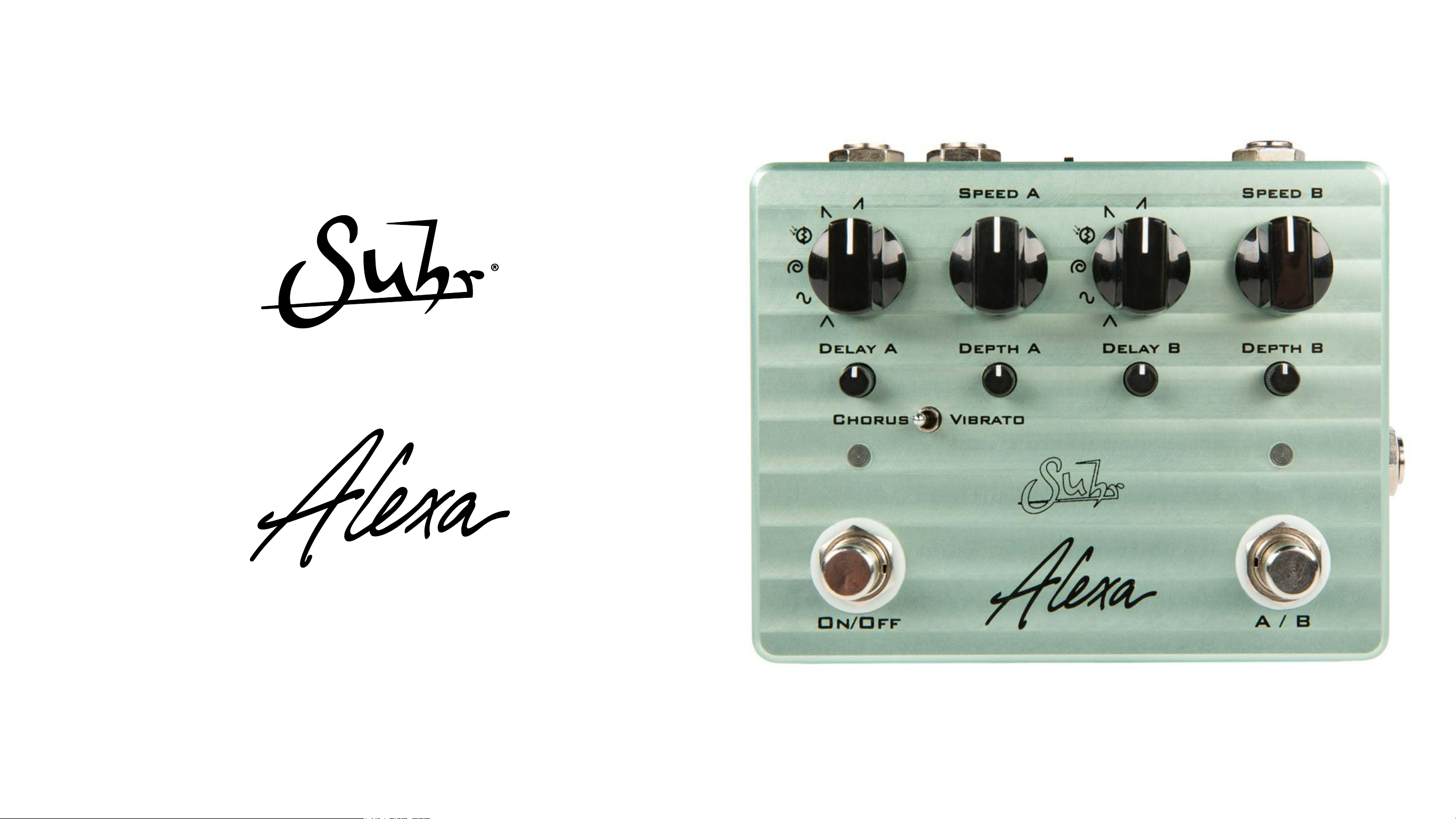
Thank you for purchasing the Suhr Alexa Analog Chorus Pedal.
Please take the time to read this manual to get the most out of the pedal.
The more you familiarize yourself with the features of this pedal, the more
you will enjoy its benets and maximize its potential.
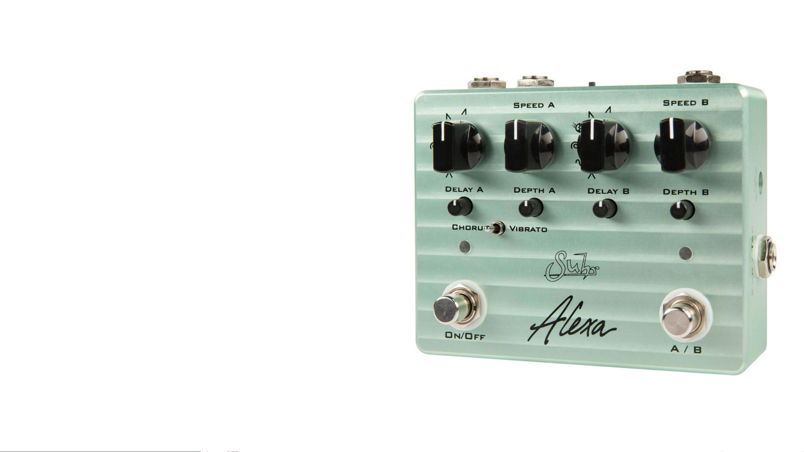
Overview
The Suhr Alexa is a two channel, analog stereo chorus with digital control.
Utiilizing bucket brigade technology, classic chorus tones are achieved with
the extra flexibility of new waveforms, tap tempo and expression speed control.
Each channel contains six unique waveforms that allow you to tailor your
modulation to suite your needs. The triangle and sine waveforms are classic waveforms used in a majority of choruses, however there are two new
custom waveforms, the rotary and photo cell waveforms that allow the Alexa to achieve swirling rotary sounds or pulsing vibe-like sounds. With the
final ramp up and ramp down waveforms, rhythmic chorus tones can be
achieved that give a delay-like effect on sustained notes.
Each channel contains an individual Speed, Depth, Delay and Waveform
option. Channel A contains a switch that allows for Vibrato as well. Wether
you want to have a chorus that can switch from slow lush chorus to a fast
rotary chorus with a hit of a botton, or use it like no chorus has been used
before with the ramp waveforms, Alexa can cover a large range of analog
chorus tones and more.
3
Page 4
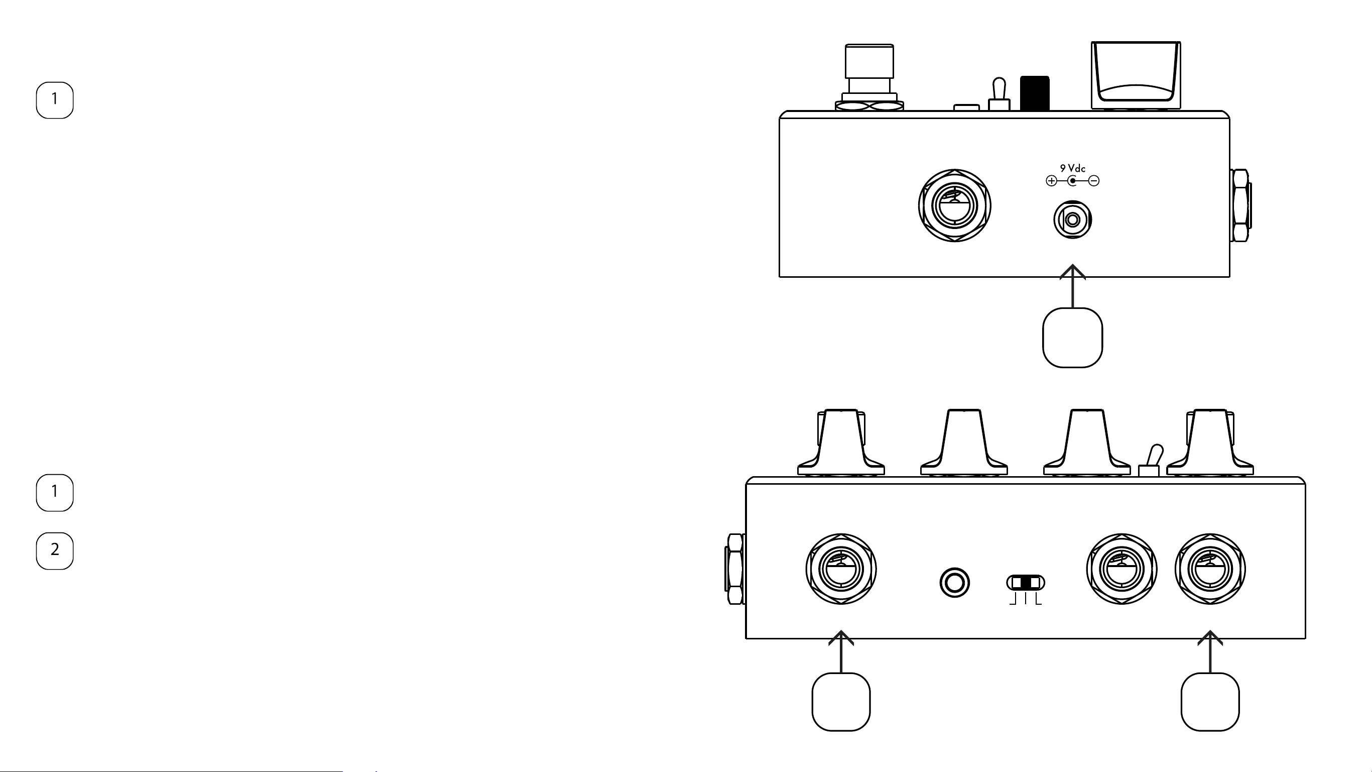
Powering Alexa
DC Input: Alexa powers with a 9Vdc regulated, center-negative power
supply that can supply 100mA or more, such as a BOSS PSA power
supply.
Getting Connected (Mono)
Exp / Tap
1
Input: Plug the cable from your guitar into here, or from the previous
effect’s output.
Output: Plug a cable from here to an amp or another effect’s input.
4
INPUT
1 2
FX LINK
OFF
FL
ON
OUTPUTS
R
L (MONO)
Page 5
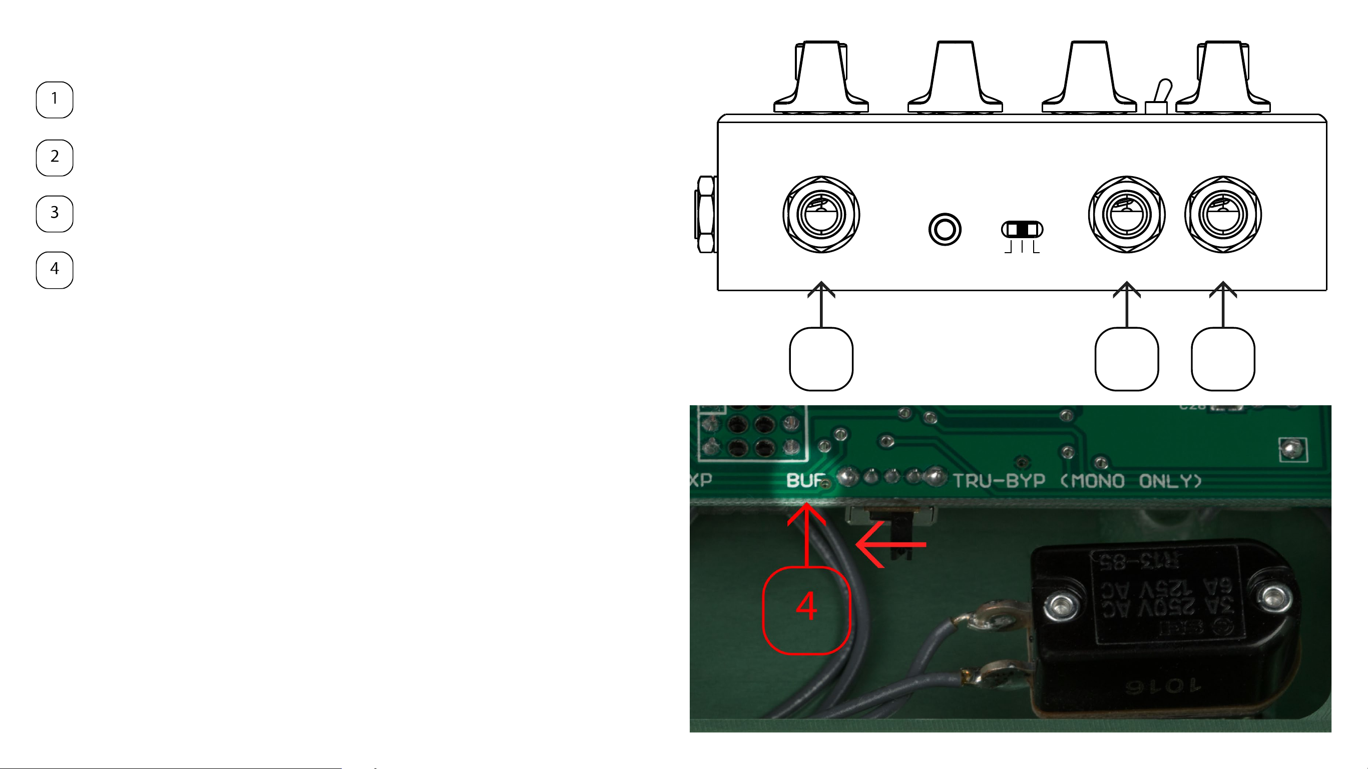
Getting Connected (Stereo)
Input: Plug the cable from your guitar into here, or from the previous
effect’s output.
Output Right: Plug a cable from here to the right amplifier (or another
effect’s input) for the right channel of the chorus.
Output Left: Plug a cable from here to the left amplifier (or another
effect’s input) for the left channel of the chorus.
BUF / TRU-BYP switch: Located on the inside of the pedal are two
slide switches. The right switch determines if the pedal is in buffered or
true bypass mode. Switch to buffer bypass (BUF) for stereo operation.
Restart the pedal by powering it off and back on to finish setting it in
buffer bypass mode.
WARNING: The true bypass feature is dedicated for the left output only. When
using Alexa in stereo, please set the pedal to buffer bypass, which is located
INPUT
1 32
FX LINK
OFF
FL
ON
OUTPUTS
R
L (MONO)
on a switch on the inside of the pedal. When turning the effect off in true bypass, the Right channel is disconnected from the input. Buffer Bypass mode
sends a buffered signal through both outputs, and is the mode that should be
used for stereo scenarios. Alexa is shipped in buffer bypass mode.
5
Page 6

Selecting Buffer Bypass / True Bypass
When turning off the pedal, the outputs can receive a buffered signal (buffer
bypass) of the input, or the left mono output can receive a non-buffered signal
(true bypass) of the input. An internal slide switch determines whether Alexa
uses buffer bypass (labeled BUF) or true bypass (labeled TRU-BYP).
Important: Switching from one mode to another requires the pedal to be
powered off and re-powered to take effect.
6
Page 7

Channel Selection / Bypass
Alexa has two channels (green and red) with independent settings that are
selected by the switch labeld A/B [2]. The channels can be set for the same
sound on each channel with slight modifications, or they can be radically different.
The left side is Channel 1 and is indicated by a green LED above the A/B
footswitch [2].
The right side is Channel 2 and is indicated a red LED above the A/B footswitch
[2].
Bypass
Stepping on the ON/OFF footswitch to bypasses the effect.
NOTE: If the internal bypass switch on the inside of the pedal is switched
to BUF, both left and right outputs get a buffered input signal. If the in-
Speed A
VibratoChorus
Speed B
Depth BDelay BDepth ADelay A
ternal bypass switch is switch to TRU-BYP (MONO ONLY), an unbuffered input signal will pass through the left output only.
Channel Selection
Stepping on the A/B footswitch will toggle between channels A and B.
When the LED is green, Channel 1’s settings are used.
When the LED is red, Channel 2’s settings are used.
A / BOn/Off
1 2
7
Page 8

Controls
Waveform Selector: Chooses one of the 6 waveform shapes that will modu-
late the Vibrato / Chorus. A more indepth description of each waveform is on
page 9.
Speed: Adjusts the speed at which the modulation occurs. Turning the knob
clockwise sets the speed to up to 10Hz. Turning the knob counter clockwise
sets the speed down to 1/2Hz.
Delay: Adjusts the delay point that chorus modulates around. This ranges
from 10ms to 40ms.
Tip: Increasing the Delay typically gives a “wider” sound. If the chorus’s pitch
Speed A
Speed B
wobbles too dramatically, counteract by decreasing the Depth control to keep
a smoother chorus sound.
Depth: The depth knob reduces (counter clockwise) or boosts (clockwise)
the amount of modulation.
Chorus / Vibrato: This switch is only active on channel A. This allows you to
turn Channel A into a vibrato effect (pitch bending).
Depth BDelay BDepth ADelay A
VibratoChorus
A / BOn/Off
8
Page 9

Waveforms
Speed A
Alexa contains six musical waveforms to choose from when dialing in a chorus/vibrato setting.
Triangle: A classic waveform used in a majority of analog choruses.
Results in a smooth modulation. Good for a smooth lush chorus with
less noticeable pitch bending.
Sinewave: Another common waveform used on choruses. Sinewave
modulation can give a throb sound, and is a great waveform for Vibrato, as the pitch bends evenly.
Rotary: This waveform is a custom shape used to emulate the swirling
sound of a rotary speaker. It is similar to the Triangle shape in smoothness.
Photocell: This waveform emulates the photocell throb effect found
on some modulation effects that use a light dependent component to
control the modulation. It has a pulsing assymetrical shape and sound.
Ramp Down: This waveform ramps the modulation downward and repeats, which results in a rhythmic effect that is delay-like on sustained
notes.
Ramp Up: This waveform modulates in an upward direction then repeats, which results in a rhythmic effect.
9
Page 10

Selecting Expression Control / Tap Tempo
Alexa’s chorus speed can be controlled via an Expression pedal in Expression mode, or a Momentary Switch in Tap Tempo mode through
the 1/4” TRS jack located on the right side of the pedal.
The function of the EXP / TAP jack is determined by an internal slide
switch. When set to (TAP), the jack takes a mono cable to a momentary switch. When set to (EXP), the jack takes a stereo cable to an expression pedal. When changing modes, the pedal must be powered off
before taking effect.
Exp / Tap
1
10
Page 11

Using an Expression Pedal with Alexa
Plug a stereo 1/4” phone cable into the EXP / TAP jack, and into a low
impedance expression pedal, such as a BOSS FV-500L.
Make sure to set the internal EXP / TAP slide switch (pg 10) to EXP. If
set to TAP, make sure to unplug and re-plug the power after changing
it to EXP.
Press the heel back on the expression pedal to get the slowest modulation speed (1/2 Hz). The Speed A & Speed B knobs sets the max-
Exp / Tap
imum speed for their channel while the pedal is toe down. The maximum speed achievable is 10 Hz.
1
Speed = 1/2 HzSpeed = Speed Knob setting
Max = 10Hz
LOW IMPEDANCE EXPRESSION PEDAL
11
Page 12

Using Tap Tempo with Alexa
Plug a mono 1/4” phone cable into the EXP / TAP jack, and into a momentary footswitch.
Make sure to set the internal EXP / TAP slide switch (pg 10) to TAP. If
set to EXP, make sure to unplug and re-plug the power after changing
it to TAP.
Push the momentary footswitch twice to set a new speed for Alexa
Exp / Tap
1
3-Position Slide Switch
At the top of the pedal between the Input and Output jack is a 3 position toggle switch.
• When set to ON, the pedal powers on with the effect active.
• When pushed towards OFF, the pedal powers on with the effect by-
passed.
• When set to FL (center), the pedal’s power state is controlled externally
via the FX LINK jack.
12
Page 13

FX Link (External Control)
Alexa contains an 1/8” stereo TRS input jack called FX LINK that allows the
pedal to be controlled by an effects switching system with TRS control output
jacks, such as the BOSS ES-8 or ES-5.
To FX LINK jack
T = TIP
R = RING
S = SLEEVE
To Switcher Control
INPUT
FX LINK
OFF
FL
ON
OUTPUTS
R
L (MONO)
T
T
R
R
T R S
S
S
S
S
1/8" Stereo Cable
Eect OFF
Eect ON
Channel 1
Channel 2
Setup
Connect a TRS 1/8” cable into the FX LINK jack from your effects
switching system. A 1/4” to 1/8” stereo cable would typically be used.
Set the 3-position slide switch to the center (FL) on startup for external
control
1 2
A connection between the Tip and Sleeve controls Alexa’s ON/OFF state.
• When Tip is connected to Sleeve, Alexa is ON
• When Tip is disconnected from Sleeve, Alexa is OFF
A connection between the Ring and Sleeve controls Alexa’s channels.
• When Ring is diconnected from Sleeve, Channel 1 is ON
• When Ring is connected to Sleeve, Channel 2 is ON
13
Page 14

Sample Settings
Speed B
Speed A
Speed B
Speed A
Any of these sample settings can be set up on either channel with the exception of the Vibrato setting, which only works on Channel A
Channel A: Lush Chorus Channel B: Fast Sine Rotary Channel A: Vibrato
Speed A
VibratoChorus
Speed B
Depth BDelay BDepth ADelay A
Speed A
VibratoChorus
Channel B: Fast Rotary
Speed B
Depth BDelay BDepth ADelay A
Channel A: Slow Sweep Channel B: Photo Cell Throb Channel A: Ramp Down Channel B: Ramp Up
VibratoChorus
Depth BDelay BDepth ADelay A
Depth BDelay BDepth ADelay A
VibratoChorus
14
Page 15

Technical Specications Warranty
Input Impedance: 470K Ω
Output Impedance: 470 Ω
Power Connector: 9Vdc, center negative, 2�1mm x 5�5mm
Operating voltage: 9Vdc
Maximum Voltage: 9�3Vdc
Over Voltage Protection: Yes
Current Consumption: 55mA
Dimensions: 4�875”(W) x 3�875”(D) x 1�375”(H)
Weight: 1�05 lbs
JS Technologies, Inc. (JST) warrants for lifetime from date of purchase by the
initial retail purchaser that this product shall be free from defects in workmanship. Electronic components such as capacitors, resistors, filters, transformers,
jacks, and pots are covered for 5 years. Any parts determined defective by JST
within the five (5) year term shall be repaired or replaced by JST without charge
for parts and labor provided the unit is returned, transportation costs prepaid, to
JS Technologies, Inc., 601 Crane Street, Unit A, Lake Elsinore, CA 92530, or to
such facility authorized by JST. JST will pay shipping costs to return the unit to
its owner. Defects in workmanship will be determined by JST for limited lifetime
coverage.
This warranty does not cover damage caused by accident, misuse, abuse, neglect, unauthorized or improperly performed repairs, alterations, and/or wear
and tear occasioned by use of the product, and does not include any expense
for inconvenience or loss of use while the product is being repaired or replaced.
JST expressly disclaims any liability for consequential damages arising from the
sale, use, or inability to use the product. Any warranty implied by law, includ-
FX Link Connector: ⅛” TRS jack
FX Link Max Voltage: 5Vdc
Shield -> Tip: Active Pedal
Shield -> Ring: Toggle A/B Channel
ROHS Compliant: Yes
ing any warranty of merchantability or fitness, is expressly limited to the one (5)
year warranty term for the parts on our amplifiers and electronic products. The
foregoing statements of warranty are exclusive and in lieu of all other remedies.
Workmanship lifetime warranty is limited strictly to the original retailer purchaser
of the instrument registered with JST within 10 days of purchase from an authorized JST dealer or distributor. JST will pay shipping costs to return the unit to its
owner within the mainland U.S.
The above warranty policy only applies to customers in USA. If you are an international customer, please check with your distributor and the dealer in your
country for warranty matters. Warranty issues must be handled through your
dealer or distributor. If you are an international customer who purchased (or
plan to purchase) from a US dealer, we can handle warranty matters direct but
you will be responsible for shipping both ways. We encourage international customers to purchase through your local distributor or dealer for this reason. Our
international distributors are set up to handle warranty issues in their respective
countries. If you do not have an authorized Suhr dealer in your country, please
contact us direct for further details.
15
Page 16

NOTE: This equipment has been tested and found to comply with the limits for a Class B digital device, pursuant to part 15 of the FCC Rules. These limits are de-
signed to provide reasonable protection against harmful interference in a residential installation. This equipment generates, uses and can radiate radio frequency
energy and, if not installed and used in accordance with the instructions, may cause harmful interference to radio communications. However, there is no guarantee that interference will not occur in a particular installation. If this equipment does cause harmful interference to radio or television reception, which can be determined by turning the equipment off and on, the user is encouraged to try to correct the interference by one or more of the following measures: - Reorient or relocate the receiving antenna. - Increase the separation between the equipment and receiver. - Connect the equipment into an outlet on a circuit different from that to
which the receiver is connected. - Consult the dealer or an experienced radio/ TV technician for help.
Changes or modifications not expressly approved by the party responsible for compliance could void the user’s authority to operate the equipment.
This device complies with part 15 of the FCC Rules. Operation is subject to the following two conditions: (1) This device may not cause harmful interference, and
(2) this device must accept any interference received, including interference that may cause undesired operation.
 Loading...