

Page 1

Build Manual
Suffolk C-type
Suffolk Sportscars Ltd
P.O Box 100, Woodbridge, IP12 9BA
www.suffolksportscars.com
Admin & Sales tel: 07967 339424 - email: [email protected]
Workshops tel/fax: 01728 745055 - email: [email protected]
Issue No: 011014
Page 2

2
Dear Customer,
Suffolk C-type Owners Build Manual
We hope that your chosen project of self building a Suffolk C-type will be as enjoyable as driving your car
following it’s completion.
Our emphasis is very much directed towards supplying the parts and assisting self build owners in the
satisfactory completion of their C-type. This manual is written logically and without jargon to take you
through the build process from start to completion. With this manual, to make the build even more straight
forward, is a picture CD ROM with index numbers corresponding to the manual.
You are most welcome to visit and revisit us to learn more, take photographs and talk to Philip, Mike, Fraser
or myself about building a car. You may not wish to, or be able to undertake some sections of the build
process yourself and we can carry out these on your behalf. We are here to help and ensure that your build
goes smoothly and according to your original plan.
Yours sincerely,
Page 3

3
Contents
Page
Foreword ................................................................................................................................. 2
Contents ............................................................................................................................... 3-4
Picture CD ............................................................................................................................... 5
Origins and Spec ..................................................................................................................... 6
1. Introduction ......................................................................................................................... 7
2. Garage and Tools ................................................................................................................ 7
2.1 Principal Tools Required ............................................................................................ 7
3. Fasteners ............................................................................................................................. 7
4. Building up the Chassis plus Suspension and Final Drive ................................................. 8
4.1 Chassis Kit .................................................................................................................. 8
4.2 Fitting Belly Pans ........................................................................................................ 8
4.3 Front Suspension ......................................................................................................... 9
4.4 Rear Suspension and Final Drive .............................................................................. 10
5. Brakes, Clutch and Pedal Box .......................................................................................... 11
5.1 Clutch ........................................................................................................................ 11
5.2 Brakes ........................................................................................................................ 12
Front Brake Lines ................................................................................................ 12
Rear Brake Lines ................................................................................................. 12
5.3 Handbrake ................................................................................................................. 13
5.4 Pedal Box .................................................................................................................. 13
RDH Brake Pipe Locations & Sizes ..................................................................................... 14
6. Engine and Gearbox .......................................................................................................... 15
6.1 Matting Engine to Gearbox ....................................................................................... 15
6.2 Preparing for Installation of Engine & Gearbox Assembly ...................................... 15
6.3 Installing Engine & Gearbox .................................................................................... 15
7. Steering ............................................................................................................................. 16
8. Fuel System ....................................................................................................................... 16
9. Ancillaries (pre-body fitting) ............................................................................................ 17
9.1 SU Carburettors ......................................................................................................... 17
9.2 Weber Carburettors ................................................................................................... 17
9.3 Alternator/Dynamo ................................................................................................... 18
9.4 Radiator ..................................................................................................................... 19
10. Body Build Guide ........................................................................................................... 19
11. Fitting Body Centre Section ............................................................................................ 22
12. Ancillaries (post-body centre fitting) .............................................................................. 22
12.1 Rear brake pipe and bleeding brakes ...................................................................... 22
12.2 Fuel pipe, fuel filter and regulator .......................................................................... 22
12.3 Ignition coil ............................................................................................................. 23
12.4 Exhaust .................................................................................................................... 23
12.5 Dashboard ............................................................................................................... 23
13. Electrical and wiring ................................................................................................ 24 - 31
14. Battery tray, battery and cut off switch ........................................................................... 32
15. Rear body and doors ....................................................................................................... 32
16. Rear valance and spare wheel cover ............................................................................... 33
17. Rear lamps ...................................................................................................................... 33
18. Bonnet ............................................................................................................................. 34
19. Front lamps ..................................................................................................................... 34
20. Interior fittings ................................................................................................................ 35
20.1 Interior floor and side panels .................................................................................. 35
20.2 Gearbox and prop shaft covers ................................................................................ 35
20.3 Seat belts ................................................................................................................. 35
20.4 Seats ........................................................................................................................ 36
Page 4

4
21. Exterior fittings ............................................................................................................... 36
21.1 Bonnet straps ........................................................................................................... 36
21.2 Headlamp covers ..................................................................................................... 36
21.3 Front grille ............................................................................................................... 37
21.4 Front screen ............................................................................................................. 37
21.5 Brooklands screens and rear view mirror ............................................................... 37
Transmission Cover Preparation Guide ................................................................................ 38
22. Finishing items and extras .............................................................................................. 39
22.1 Wheels and tyres ..................................................................................................... 39
22.2 Tonneau cover ......................................................................................................... 39
Parts List ....................................................................................................................... 40 – 43
C-type Hardware List ..................................................................................................... 44 - 51
Rubber & Polybush Types and Positions ............................................................................. 52
Photo Index ........................................................................................................................... 53
Photos ....................................................................................................................... 54 - 63
Page 5

5
Mount picture cd here
Page 6

6
Suffolk C-type
Origins
In 1951,Jaguar Cars Limited entered three cars for the Le Mans 24 Hour Race. This was their first attempt at the greatest endurance event in motorsport.
Aerodynamic expert Malcolm Sayer and chassis expert Bob Knight had designed the XK C-type in secret, powered by the all-new Jaguar 3.4 litre XK 120 engine
designed by Walter Hassan and Claude Bailey, the unit produced 200bhp.
In night practice for the historic race, driver Peter Walker shattered the existing lap record with an average speed of 104mph. In the race he and Peter Whitehead
triumphed with first place for Jaguar in a race that became the forerunner for two more Le Mans victories in 1953 and 1954.
In 1960, Roger Williams commenced a management-training course in Ipswich with Jaguar distributer Botwoods Limited. Days at the Jaguar factory in Browns
lane and collecting Jaguar E-types from the works were all parts of life and memorable highlights of five years with the Jaguar dealership.
In 1995, Roger Williams created Suffolk Sportscars Engineering to manufacture modern reproductions of the 1936 Jaguar SS100. To date over 180 cars have
been built for discerning Jaguar enthusiasts all over the world. The idea of recreating the C-type has been a dream ever since Peter Walker crossed the line in “774
RW”. Suffolk Sportscars has built several C-types already including a car for demonstrations and test drives and will be building a limited number of cars each
year.
On The Road
The Suffolk C-type is as visually close as one can practically achieve to the original cars that won Le Mans in 1951 and 1953. The original Jaguar C-type XKC
039 was used to form all our body moulds and is therefore dimensionally perfect.
At the Jaguar speed trial in 2006, our demonstrator 662 EBY, a 3.4 litre car achieved 138mph, and was still accelerating as it passed the timing beam. The
handling is taut and true to the C-type tradition. The suspension and brakes are all modern versions of the components used by Jaguar in 1953.
This car will give the owner a driving experience equal to that felt by Tony Rolt and Duncan Hamilton when they won Le Mans in 1953.
Personal Thoughts
History tells us everything, books like Philip Porter’s 1995 ‘Jaguar Sports Racing Cars’ inspire many readings to absorb the wonderful atmosphere. A few lucky
guys like myself have the team and the tools to recreate the amazing Jaguar C-type. Can any other reproduction of a Le Mans winning car inspire so much and yet
come at a price that is such a small fraction of the original’s value.
Our car is created to be exact in its dimensions and rewarding in its dynamic performance. The prototypes have been raced, toured and used on track days so are
well tested and give performance and handling every bit as good as the original. We have marginally improved the driver’s comfort but this is a no nonsense, no
heater, no hood and no prisoners’ car.
In The Cockpit
The view and the layout are exactly as the original 1953 C-types. Every effort has been made to ensure the Suffolk C-type looks and feels correct. Leather seats
and Hardura coverings to the transmission tunnel contrast with the bare alloy and black instruments and steering wheel. Storage space for light luggage items and
tools is included. All cars have improved legroom, driver comfort in the cockpit, servo brakes, safety steering column and fitted seatbelts.
Construction and Purchase
We are pleased to fully build the Suffolk C-type to customer’s requirements. New factory built cars can be supplied with an SVA certificate and a UK MoT
certificate. Age related number plates are available and cherished numbers can be transferred.
The Suffolk C-type can be purchased in component form or as a part built rolling chassis for customer completion. Suffolk Sportscars can supply every
component necessary for a self-build program and maintains a full after sales and works support program.
We welcome visits to our workshop to see our demonstrator and other cars currently being built. Additional information about Suffolk Sportscars’ builds can be
found on our website.
Bodywork and Interior
The body is made of reinforced GRP incorporating alloy panels wherever possible to keep them looking as original as possible. Louvres to the bonnet are in alloy,
Leather seats, Hardura over transmission covers, Lexan main screen and Mohair tonneau cover.
Typical Specification
Chassis Mig welded 16swg steel tubes with square and folded sections-all visually exact to the 1953 Jaguar design
Front suspension Jaguar E-type torsion bar and shock absorbers with Anti-roll bar
Rear suspension Jaguar MkII live axle with trailing links and A bracket reaction plate (or link with Panhard rod)
Steering Rack and pinion
Brakes Lockheed 11inch discs (servo optional)
Wheels 16inch 5J 72 spoke wires
Tyres Blockley 6.00 x 16 High Performance
Engine Jaguar XK
Displacement 3.4, 3.8 or 4.2
Bore and stroke To suit engine
Compression ratio Various (8.4:1 typical)
Power From 200bhp
Exhaust As per 1953 Jaguar works car
Transmission Jaguar or Tremec
Gear ratios Various 4 and 5 speed options
Final drive Live axle 3.54 or 3.31. LSD optional
Dimensions Exactly as 1953 Jaguar XK120 C-type
Length 13′ 1 ½″
Width body 5′ 0″
Width with spinners 5′ 3″
Height 3′ 6 ½″
Ground clearance 5″
Frontal area 13.81sq.ft
Wheelbase 8′ 0 ½″
Front track 4′3″
Rear track 4′3″
Page 7

7
1 Introduction
The scope of this manual is to provide all the information necessary to build the Suffolk C-type replica.
It assumes that all donor car parts are supplied by Suffolk Sportscars, fully refurbished and built into
subunits where necessary, ready for assembly along with all other parts required for completion of the car. If
a builder wishes to refurbish donor parts himself he should contact Suffolk Sportscars for advice first.
2 Garage and Tools
A single sixteen by eight foot garage is sufficient space to build the Suffolk C-type, but more room is useful.
You will need a small workbench and a vice.
2.1 Principal Tools Required
• Spanners - combination sets covering 3/8” - 1” AF and 10 – 26 mm
• Sockets sets – 1/2 inch drive covering 3/8” - 1” AF and 10 – 26mm
• Torque wrench – 1/2-inch drive of 100-ft/lb capacity
• Mains and/or battery drill with 1/2 inch/13mm chuck
• Drill bits – 1 – 13mm in 0.5mm steps
• Taper taps – various sizes, imperial and metric
• Allen keys - imperial and metric sets
• Selection of basic hand tools - screwdrivers, pliers, files and hacksaws etc
• Electrical test meter
• Side cutters and crimping pliers
• Sheet metal cutters for adjusting aluminium panels
• Nutsert set with selection of sizes
• Four axle stands - rated at one tonne each
• Trolley jack – a basic one will do but a two tonne model giving a fifteen-inch lift is well worth the
money
• Engine crane – capable of lifting up to one tonne. If you don’t wish to purchase one or have no place
to store one it is easy to hire an engine crane for a couple of days from a number of hire companies
3 Fasteners
Suffolk Sportscars can supply all nuts, bolts, washers and fasteners. This package comes as a complete and
comprehensive kit that gives descriptions, sizes and locations for chassis and body build.
Most Jaguar components use unified (imperial) threads, mostly UNF (fine thread) but UNC (coarse thread)
is also used for threads in aluminium. Exceptions are steering racks on some later cars where the track rod
ends are threaded. M14 fine (1.5mm pitch) and later brake master cylinders use metric threads. SU
carburettors use BSF and BA. Fuel tank senders are 2BA and Weber carburettors use metric.
It is recommended that stainless steel fastenings be used for fittings to the body and for those directly
exposed to road dirt and salt. Stainless fasteners in unified threads are difficult to obtain but metric ones are
readily available and are used for this reason wherever possible. It is also recommended that all non stainless
steel fasteners are high tensile bright zinc plated (BZP).
Page 8

8
4 Building up the Chassis plus Suspension and Final drive
4.1 Chassis kit
Parts required 001
A Main tubular chassis
B Front frame C/W lower fixings 2 of 5/16” UNF x 1”
Upper fixings C/W inner Wishbone mounts
C Rear frame C/W Lower fixings 2 of 7/16” UNF x 3”
Upper fixings 2 of 3/8” UNF x1”
This is fitted after the rear suspension and final drive
D+E Engine bay brace
C/W 8 of 5/16” UNF x 1”
This is fitted after installation of the engine and gearbox assembly
F Gearbox bracket C/W 4 of 3/8” UNF x 1”
This can be fitted anytime before installation of the engine and gearbox assembly
G Belly pans (9 pieces)
4.2 Fitting belly pans
1. To begin assembly start with the chassis upside down and temporarily mount the rear frame to the
chassis.
2. Lay on the rear frame belly pan and check for fit. Trim if necessary and clamp in place (always use
something to protect the panels and chassis from clamping damage). The belly pan should be the
same size as the rear frame but long enough to reach the rear chassis rail.
3. Mark out equal positions on the rear belly pan down the sides and across the rear before drilling belly
pan and rear frame to suit your chosen fixing method (this panel can be riveted and bonded on as it
does not need to be removable).
4. Remove panel to clear away any swarf before applying bonding medium if required and laying on
and fixing the belly pan to the rear frame.
5. In the centre of the rear belly pan is an access panel to the differential and handbrake; this needs to
be removable and we recommend fixing this using Rivnuts. These are basically nuts riveted into the
belly pan allowing setscrews to be easily fitted and removed without loss of thread.
6. Next, lay on the centre panel (wide end towards the front, all belly pan swages point down away
from the chassis) and line up the edges to run along the edges of the ‘C’ section chassis rails. The
holes in this can then be marked through into the chassis.
7. Remove the panel before drilling to accept your chosen fixing method (again we would recommend
Rivnuts as this panel needs to be removable).
8. Once the fixing holes are drilled and Rivnuts fitted, drill clearance holes in the panel to the correct
size for the fixings you’re using before returning the panel and securing on one side only.
9. Check the other side holes all line up before marking the position of the centre tube cross member on
the centre panel and the body mounting flange. Take the side panel for the side not fixed down and
slide it under the centre panel making sure the returned edge is against the chassis rail (the left hand
panel will need trimming around the handbrake cable bracket).
10. Align the panel with the body-mounting flange.
11. The holes in the flange can be marked on the panel ready to drill to 8mm and the holes down the
centre rails can be marked to match the positions in the centre panel. Also mark and pilot drill two
equally spaced positions through the panel into the tubular cross member before removing the panel
drilling the outer mount holes and drilling the tubular chassis and fitting with Rivnuts. Repeat with
second side.
12. Refit the outer panels and lie on the front triangular belly pan sections (these have a step to overlap
the main belly pan sections), and fix in the same way as the main sections. These five panels can
then be removed for safe storage during the build and the rear frame removed until later in the build.
Page 9

9
13. With the rear frame removed you can rivet on the final pieces of the belly pan set comprising the
boot floor (this will need flexing to pass through the frame) and the rear bulkhead which rivets on the
outside of the frame.
14. The main tubular chassis can then be turned the correct way up and stood on four axle stands as level
as possible ready for building the suspension assemblies.
4.3 Front Suspension
Parts required 003–021 +027
1. Take the front lower wishbone poly bushes (007), lightly lubricate and insert them into the four tubes
in the chassis. Once the poly bushes are in, lubricate and fit in the metal sleeves.
2. You can fit the lower wishbones (004). To establish the correct wishbone the inner end is splined for
the torsion bar and should be offset forward and the outer ball joint end turns upwards.
3. Apply copper grease to the pivot shaft (005) and slide this through the wishbone (hole nearest the
splined torsion bar hole) from front to back then add on the first of the three large holed serrated
washers then pass the pivot pin through the front chassis upright. On the pivot pin between the front
and rear uprights you can now slide on the second serrated washer followed by the spacer tube and
lower tie bar (006) with its outer end pointing forwards to meet the lower wishbone, then slide on the
third serrated washer before passing the pivot pin through the rear chassis upright. Finish off by
fitting the last serrated washer with the small hole and the castle nut but do not tighten yet.
4. Line up the wishbone and the tie bar and pass through the 1/2” UNF bolt with one plain washer
already on from the front (this bolt also locates the front damper (027) which can be mounted with
“c” clip facing rearwards). Use the second washer and nut to secure. You can tighten this but don’t
fit top mounting bolt yet.
5. Next take the torsion bar (016) and slide the teardrop mount (017) over the rear end slightly up the
bar. The front end of the torsion bar has a location groove and the teardrop mount splined and
extends rearward. You can then slide the torsion bars through the rear location on the chassis from
the engine bay. Drop the front end down and pass forwards through the chassis into the lower
wishbone and locate in the wishbone with the M5 bolt supplied through the location groove
6. Next make sure the wishbone is at its lowest point before sliding the torsion bar teardrop rearwards
and locating in the chassis mounting with the 3/8” UNF x 1” supplied in the inner mounting hole.
This hole is slotted and acts as a position-locking bolt. The outer mount hole of the torsion has an
adjustable mount to aid suspension height setting. Take the supplied 3/8 UNF x 2 1/2 setscrew fit on
a plain washer and pass it through the torsion bar adjuster mount bracket from the underside (the
bracket mounts on the chassis with the single hole in the horizontal and the twin hole section
pointing upwards) before adding another plain washer and a Nyloc nut. Screw this down until
almost tight.
7. Next screw on a plain nut and lock washer followed by the ‘C’ shaped adjusting bracket, this can
then be attached to the torsion bar outer mount hole with a 3/8UNF x 1 1/2 bolt with washers and
Nylocs.
8. Once this is hanging in position screw the adjusting bolt to get the head of the bolt just in line with
the level of the chassis before marking the mounting hole positions. These can then be drilled and
the brackets bolted in place.
9. Extend the damper and pull up into the top mount. You may need an assistant to do this as you are
putting pressure on the torsion bar. Use extra washers as shims to centralise the top of damper and to
stop the mount being squeezed in when tightened.
10. Now you can tighten the lower pivot pin castle nut and lock with a split pin.
11. Next take the upper wishbone inner mount (011) and secure with the lower mounting bolts whilst
using the top bolts to hold the holes in alignment. Before tightening the lower bolts add the slide in
shims, which control the camber angle. Four shims in each position will give a little negative
camber; five will leave it nearer neutral. The suspension settings will all need checking and adjusting
once the car is fully built.
Page 10

10
12. The top ½” UNF x 3” bolts locate into the cross brace bars (003). The rear bar may need a couple of
washers/shims to fit the gap and is best left out until the engine is fitted, whilst the front bar can be
fitted but in co-ordination with the front frame.
13. Locate the front frame with the brackets on the inside of the main chassis and pass the upper
wishbone mount bolts through the front frame mounts and then into the cross brace. Secure the
lower end of front frame with 5/16” UNF bolts and nuts supplied.
14. Lightly lubricate the upper wishbone poly bushes (010) and assemble in upper wishbones (009).
Hand pressure should be sufficient; then push in the metal sleeves.
15. Copper grease the pins of the upper wishbone inner mount and slide on the wishbones. Both
wishbones crank in towards each other. The more cranked wishbone is the rear item. Hold on with
large plain washers and half Nylocs but don’t tighten yet.
16. Between the outer ends of the top wishbones you can now mount the upper ball joint (012) using the
3/8” UNF x 3 ” supplied. Install three shims behind each ball joint, which can be changed later to
adjust castor angle. With the ball joint tight you can also tighten the inner mount Nylocs.
17. Next take the lower ball joints (008) and pass them through the lower end of the front uprights (013).
Secure with the 5/16” UNF and lock washers supplied. Before fitting the upright on the car remove
any paint from the inner surface of the front threaded lobes where the brake calliper locates. If your
upright has two different spaced arms (vertical distance between front and rear arms) the larger
spaced pair go towards the front of the car and are for the brake calliper, fit the upright to the upper
and lower ball joints and torque to 50 and 55 ft lbs respectively. With the upright fitted you can now
fit the stub axle (013) and steering control arm (024), the stub axle passes through the upright and the
inner end of the steering control arm and secures with the large nut supplied (torqued to 85 ft lb), the
steering arm needs to point to rear of car and mounts on the upper of the two bolt holes with the
steering arm finishing horizontal for the track rod end.
18. Take the front hubs (014) and mount on the front brake discs (019) with the 7/16” UNF x 1 ½”
supplied. Pass the bolts through the back of the brake disc then through the hub followed by plain
washers and metal lock nuts.
19. Keeping the front wheel bearings (015) as matched units press the outer race of each into the hub.
Thoroughly grease the inner race of each making sure you rotate them to work the grease in before
installing in the hub then press in the rear grease seal.
20. Now locate this on the stub axle of the front upright and fit the flat D washer and castle nut, tighten
the hub nut whilst turning the hub at the same time until its rotation is felt to be slightly restricted.
Now back off the castle nut between one and two flats and insert split pin to secure using the hole in
the side of hub to help.
21. Clean the protective grease off the brake disc before fitting on the brake calliper (018) to the front of
the assembled hub carrier using the supplied cross drilled 7/16” UNF bolts. Use an extra washer as a
spacing shim if necessary to centralise the calliper over the disc then lock wire the bolts together.
22. Lightly copper-grease the rear non-friction side of the brake pad to help avoid brake squeal before
inserting into the brake calliper and securing with pins (copper greased to aid sliding) and “R” clips.
23. Take the anti-roll bar (020) with its “D” brackets and poly bushes, lubricate the poly bushes and slide
them over the middle section of the roll bar (they are split bushes to help this). Mount centrally to
the underside of the chassis with the “D” brackets and 3/8” UNF bolts, washers and Nylocs.
24. The drop links (021) link the ends of this bar to the last spare hole in the lower front wishbones.
4.4 Rear suspension and final drive
Parts required 028-038
1. Next turn to the rear end and assemble the rear radius arms (034). The larger hole and bush is the
front chassis mount end and the three holes mid way along are along the top; they are not handed.
Take the front plate with the welded sleeve and keeping the weld to the outside of the car push it
through the radius arm. Then fit the other plate on the inside and secure together with 5/16”UNF
bolts with washers and Nylocs on the outside.
2. Next, install the rear bush carrier with its welded sleeve keeping the weld innermost and secure with
5/16” UNF and lock washers (the holes may need threads taping to 5/16 UNF). Now lightly lubricate
Page 11

11
the front-end poly bushes and slide them in followed by the metal sleeve and do the same with the
smaller rear bushes. You can now grease the rear radius arm mount pins on the rear end of the
chassis and slide on the radius arms, locate with washer, castle nut and split pin.
3. Then install the rear dampers (033) with 1/2”UNF bolts with flat washers and Nylocs from the top
chassis mount to the centre of the three radius arm holes. The top mount may need washers or small
shims to centralise before tightening both fixings.
4. Bring the final drive differential assembly to the rear of the chassis with the prop shaft mounting
flange pointing upwards and the long brackets facing forwards. Locate these brackets with the rear
radius arm rear bushes in the centre and secure with 7/16”UNF bolts washers and Nylocs.
5. Before rotating the final drive into position prepare the two tie bars (037) by loosely bolting them to
the shorter brackets from the rear differential tubes that currently face backwards with 7/16” UNF
bolts washers and Nylocs. Fit the two rose joints with lock nuts and star washers before screwing
half way into the tie bars leaving loose at this point for adjustment.
6. Prepare the Panhard rod (038) by fitting its rose joint with lock nut and star washer on one end,
lubricate and press in the poly bush in the other end followed by the metal sleeve. Copper grease the
pin on the right hand side differential tube that currently points upwards and slide on the Panhard rod
with the centre hole of the rod lying over the prop shaft flange. Loosely fit the large flat washer and
9/16” UNF Nyloc.
7. You are now ready to rotate the differential into position and secure with the 1/2” x 2 1/2” UNF bolts
with lock washers through the rose joints into the chassis. Depending on the type of rose joint a
spacer may be required to hold the rose joint and lock nut away from the chassis as you don’t want it
to rub when moving up and down. Check the tie bars are holding the differential prop shaft flange as
vertical as possible. If necessary release the rose joints adjust and refit before tightening both ends.
8. The Panhard rod is there to hold the differential central to the chassis. Make sure it is central before
adjusting the rose joint and securing with 1/2”x 2”UNF bolt (in whichever hole holds it most central
over the differential), washers and Nylocs and tighten both ends and Nylocs.
9. Assemble the rear hubs (030) to the rear brake discs (032) with the 7/16”UNF bolts supplied. Pass
the bolts through the rear of the discs then locate the hub followed by flat washers and metal lock
nuts. This can now be installed on the final drive. With the key installed on the drive shaft (these
may need adjusting with a file to be a snug but not over tight fit) grease the shaft before sliding on
the rear hub and attach with washer castle nut and split pin.
10. Clean the transit grease off the brake discs before fitting on the rear brake calipers (031) with the
cross drilled 7/16” UNF bolts supplied. Using an extra washer as a shim if necessary equal on both
bolts to centralise the calliper. Lightly copper grease the rear non-friction side of the rear brake pads
before sliding into the brake caliper and secure with lock plate or pins provided.
11. Attach the rear handbrake calipers above the foot brake calipers with the supplied pins and “U”
springs, tighten the adjusting screw which passes through the top of the caliper until the disc is tight
to turn. Then back of a little until it can turn freely, line up the slot and secure with split pin.
12. Once finished the four corners of the suspension and hubs should be thoroughly greased via the
grease nipples fitted: one on each front hub and one on each end of the differential tubes for the rear
wheel bearings.
5 Brakes, Clutch and Pedal box
IMPORTANT SAFETY NOTE
The components of the hydraulic circuit have a mix of metric and imperial connections. The brake master
cylinder use’s metric M10 and M12. Most other parts of the system use imperial 3/8”UNF.Take care to
ensure correct fittings are used as incorrect ones may seem to fit but will not seal properly and could strip
the thread. Unions are generally gold in colour for metric and silver for imperial. Make sure unions are
tight enough to seal but not over tightened. A torque wrench is not suitable here but a torque of about 15 ft
lb is appropriate.
Page 12

12
5.1 Clutch
Parts required: - 042
1. Start off by removing the blank from the clutch master cylinder (042) and screw in one end of the
clutch flexi hose. On the other end screw on the Banjo union supplied with the clutch slave cylinder
(this will be connected up once the engine and gearbox assembly has been fitted). Pass the push rod
end of the master cylinder through the mounting hole just in from the torsion bar mount and secure
with the 5/16” UNF supplied. The clutch will be finished off once the engine and gearbox are fitted.
5.2 Brakes
Parts required: - 039 – 041
1. Start with the master cylinder and servo (040). Mount the master cylinder using the mount plate with
captive studs. Pass these through the mount position next to the clutch master pointing forwards
before offering up and securing the master cylinder with the two washers and nuts supplied. Next
mount the servo on its mounting plate. These holes are unequal so it will only mount one way round
(the servo needs to be mounted in a particular orientation to work correctly) before mounting the
bracket on the chassis with the three 5/16 UNF x 1 bolts washers and Nylocs.
2. The two fluid reservoirs mount with clamp plates to the two lugs welded to the chassis tube above
the brake servo. These can be test fitted with the connection pipes but will need removing before the
body can be fitted.
Front brake lines
1. Start off by fitting the two front flexi hoses (041) by screwing them into the front brake callipers, the
other end can then be secured with the nut and star washer to the front of the chassis just ahead of the
upper damper mounting pointing towards each other making sure not to twist or kink the hoses.
2. Next mount the front 3way union to the front upper chassis cross member (there should be a hole for
this in line with the right hand steering rack mount) with the unions pointing left, right and down.
3. Run the front left brake pipe F3 from the left of this connector behind the top cross member then up
and over near the end weld gently bending to suit without kinking to meet the flexi hose, connect up
to the hose and secure the pipe behind the cross member with two plastic “P” clips. Repeat with the
shorter right hand pipe F4 and secure with a “P” clip if necessary.
4. Next fit the second 3way union on the inside of the angle chassis tube near to the master cylinder
where there should be a 1/4” UNF taped hole (the union needs to be in line with the chassis with the
third outlet pointing up and back).
5. The rear inlet of the union needs to be connected to the outlet on the end of the servo with pipe F2.
Pipe F1 then connects from the master cylinder to the side inlet on the servo.
6. The front outlet connects to the front 3way union with F2 this can be run either through or over the
chassis engine mount and secured with two more “P” clips. Finish the front end pipes by fitting the
brake lamp switch in the spare point in the 3way union nearest the master cylinder.
Rear brake lines
1. Start by mounting the rear 3way union on the Panhard rod mount on the rear differential pointing
left, right and rearwards.
2. Use the rear facing union for the right hand brake line R2. Screw it into the union then gently bend
it to follow the diff tube towards the left then over the differential securing by the three of the metal
“P” clips. Carry on following the left diff tube and secure again with a “P” clip in the rear of the tie
bar, mount the pipe can then turn rearwards and into the brake calliper. Do the same with the shorter
right hand pipe R3 using the right hand outlet.
3. Take the third flexi hose and connect into the last point on the rear 3way union. Pass the other end of
the hose down and under the Panhard rod and secure through the bulkhead (there should be a hole in
the right hand side at the base).
4. Secure here with the nut and star washer supplied.
5. The last pipe R1 connects this flexi hose with the rear connection on the master cylinder and runs
from the flexi along the top of the lower chassis rail then to the outside of the rail until it gets to the
front and curls up to the master cylinder. We suggest trial fitting this pipe and drilling for the plastic
Page 13

13
“P” clips to secure to the chassis but then removing this pipe for ease and safety of fitting the body.
This pipe runs along the outside of the chassis above the body-mounting flange.
5.3 Handbrake
Parts required 044
1. The handbrake mounts to the inner left hand chassis rail, beside the gearbox with the top face of the
mount flush with the top face of the “C” section chassis member and the rear end just ahead of the
tubular cross member. Secure with two 5/16”UNF bolts and Nylocs.
2. The rear handbrake cable pivot bolts to the rear differential with the longer unc bolts supplied, and
then the two handbrake link cables can be fitted between the pivot and the callipers using clevis and
split pins.
3. You can then fit the main handbrake cable. Take the end with the threaded adjuster bar and on it
screw one of the M10 nuts on the outer cable adjuster before passing it through the front cable
location bracket on the inner chassis rail. Add a shake proof washer and the second M10 nut to
secure. The threaded bar can then have the “C” bracket attached to it with one nut on each side
before attaching this to the handbrake lever with a clevis and split pin. The rear end of the cable then
passes under the chassis and through the Panhard rod and into the rear handbrake cable mount. This
is secured by two M10 nuts and a shake proof washer. You can then connect it up with another
clevis and split pin.
4. Using any or all of the three threaded handbrake adjusters, adjust the cable length so that the wheels
turn free with the handbrake off and 5-6 clicks on the handbrake locks them up.
5.4 Pedal Box
Parts required 043
1. To install the pedal box start by assembling the pedals on the shaft with the spacers supplied. The
pedals are identical and lean forwards. The angled end mount fits to the centre ‘C’ section chassis
rail and the horizontal end mount to the footboard tie plate. Offer the assembled pedal box to the
chassis and then clamp it to the chassis before taking the pedals, passing the shafts through the
footboard and securing to the pedal arms. Check pedal shafts for free movement through the
footboard releasing the clamps to reposition where necessary to allow the pedals good clear
movement. The upper part of the pedal arm should lay against and at the same angle as the heel
board with the pedal in the released position.
2. Once you are satisfied with the position mark the four mount holes before removing the pedal box
and drilling mount holes to 8mm, the pedals can then be refitted and connected to the master
cylinders with the clevis pins provided. The outer bolts will need removing at a later date to allow
fitment of the belly pans and the mount holes drilled through the belly pans before refitting the bolts
again.
3. The throttle pedal can be mounted by passing the shaft through the footboard from inside before
passing fixing bolt through the mounts and the pedal and securing with Nyloc nut.
Page 14
14
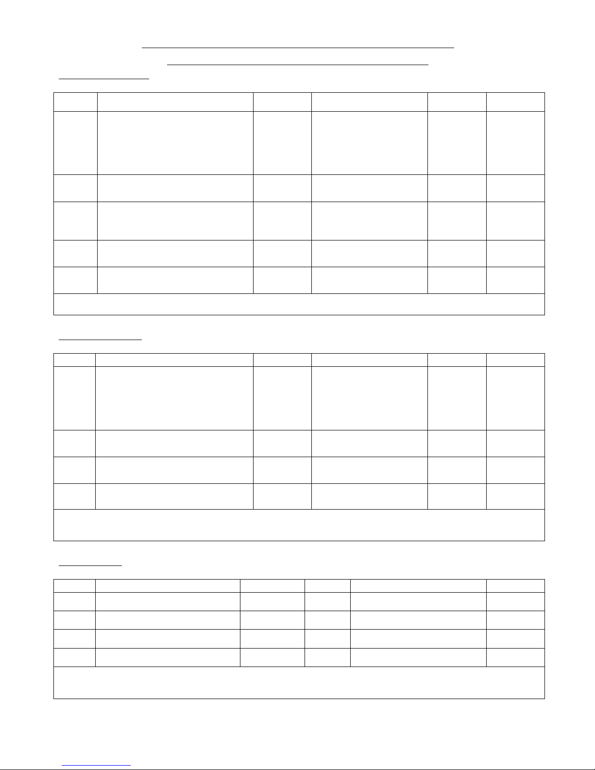
C-type - RHD Brake/Fuel Pipes Locations & Sizes
(XJ6 Master Cylinder and optional servo)
FRONT SECTION
CODE
DESCRIPTION
LENGTH
THREAD
UNION
FLARE
F1
MASTER CYLINDER TO
SERVO or DIRECT TO
3-WAY BRAKE SWITCH
CONNECTOR IF NOT USING
SERVO.
8”
10mm LATE TYPE
MASTER CYLINDER
7/16 EARLY TYPE
MASTER CYLINDER
3/8 UNF
MALE
MALE
MALE
SINGLE
SINGLE
SINGLE
F2
SERVO TO 3-WAY BRAKE
SWITCH CONNECTOR
9 ½”
3/8” UNF
3/8” UNF
MALE
MALE
SINGLE
SINGLE
F3
3-WAY BRAKE SWITCH
CONNECTOR TO FRONT 3WAY CONNECTOR
26”
3/8” UNF
3/8” UNF
MALE
MALE
SINGLE
SINGLE
F4
FRONT 3-WAY CONNECTOR
TO N/S FRONT
20”
3/8” UNF
3/8” UNF
MALE
FEMALE
SINGLE
DOUBLE
F5
FRONT 3-WAY CONNECTOR
TO O/S FRONT
9”
3/8” UNF
3/8” UNF
MALE
FEMALE
SINGLE
DOUBLE
EXTRAS:
5no. 3/16” P-clips with self tapping screws
REAR SECTION
CODE
DESCRIPTION
LENGTH
THREAD
UNION
FLARE
R1
MASTER CYLINDER TO
REAR DIFF FLEXI HOSE
65”
3/8 EARLY TYPE
MASTER CYLINDER
12mm LATE TYPE
MASTER CYLINDER
3/8” UNF
MALE
FEMALE
SINGLE
DOUBLE
R2
REAR 3-WAY CONNECTOR
TO L/H SIDE OF CAR
50”
3/8” UNF
3/8” UNF
MALE
MALE
SINGLE
SINGLE
R3
REAR 3-WAY CONNECTOR
TO R/H SIDE OF CAR
18”
3/8” UNF
3/8” UNF
MALE
MALE
SINGLE
SINGLE
R4
REAR CALIPER LOOP PIPE
X2
11 ½”
3/8” UNF
3/8” UNF
MALE
MALE
SINGLE
SINGLE
EXTRAS:
5no. 3/16” P-clips with self tapping screws
5no. 3/16” P-clips with 5/16” securing holes and 2no. 5/16”unf x 3/4 hex head, nuts, washers
FUEL PIPES
CODE
DESCRIPTION
LENGTH
CODE
DESCRIPTION
LENGTH
FP1
MAIN METAL PIPE
1700MM
FP5
FILTER TO WEBERS
600MM
FP2
TANK TO PUMP
400MM
FP6
WEBER LINKS X2
165MM
FP3
PUMP TO REAR OF FP1
840MM
FP7
FILTER TO SU ‘T PIECE’
450MM
FP4
FRONT OF FP1 TO FILTER
250MM
FP8
‘T PIECE’ TO SU’S X2
250MM
EXTRAS:
6no. 5/16” P clips with self tapping screws
4no. 5/8” P clips with bolts, nuts, washers
Page 15

15
6 Engine and Gearbox
Parts required 001 plus (gearbox brackets and engine bay brace) 052,079,081-086.
6.1 Mating engine to gearbox
1. If not already fitted, lightly copper grease the pivot ends of thrust release bearing (085).
2. Place the release bearing over the gearbox input shaft and locate pivots in the release lever. Locate
the straight ends of the spring retaining clips in the ends of the pivot and rotate the cranked ends
around behind the release lever until they click into the location points.
3. Align the engine and gearbox using a jack under the rear of the gearbox to aid support and to avoid
bending the input shaft. Lightly grease the input shaft before inserting thorough the clutch (you may
need to turn the gearbox to line up the splines). Once aligned push the two units together and line up
the dowels in the engine and bell housing. Secure together with 10 of 3/8” UNF x3” with star
washers and 4 of 3/8” UNF x11/2” with star washers and 6 Nylocs and flat washers. Once connected
bolt on the bell-housing flywheel lower cover (083) using the ¼”unc bolts supplied.
4. Fit the clutch slave cylinder (086) on the bell housing; the studs should already be fitted ready to
accept the slave cylinder. Secure with two 3/8”UNF nuts and lock washers, using the lower nut to
retain the return spring eye. Take the pushrod and screw on one 5/16”UNF nut followed by a lock
washer and the pushrod eye. Push the push rod as far into the slave cylinder as it will go (this is also
pushing in the piston in the slave cylinder), before lightly copper greasing the eye and locating in
clutch lever. Push the pin through clutch lever and push rod eye to secure. Make sure the clutch
slave cylinder piston is pushed in as far as it can then adjust out nearly all the free play in the clutch
movement. Once adjusted secure the pin using two 5/16” washers and a split pin, between the
washers where the return spring is located. The other end goes to the spring retaining eye on the
slave cylinder mount.
6.2 Preparing for installation of engine and gearbox assembly
Parts required 001,053,054,055,080
1. Attach the left and right hand engine mounts to the engine with the 7/16” UNF bolts and lock
washers. If using an alternator, turn the crankshaft pulley to line up the timing marks with the pointer
and remove the two lower most bolts on the left side of the timing cover. Fit on the alternator
bracket using the longer bolts supplied. Tighten the bolts ensuring that the timing mark pointer still
lines up.
2. Screw the threaded adapter and rubber mount into the rear underside of the overdrive unit.
3. Next prepare the chassis. Start by fitting the gearbox mount cross member (001) to the chassis with
four 3/8”UNF bolts. The plate must hang down from the bolts with gearbox mounting hole slightly
offset to the left of the chassis. Then loosely mount the rubber engine mounts on the chassis with the
5/16”UNF bolts supplied.
4. If the gear lever is fitted remove this before attempting to install the engine/gearbox as it will not
pass under the dash chassis cross member.
5. You are now ready to install the engine and gearbox assembly.
IMPORTANT SAFETY NOTE
The engine and gearbox weigh in excess of 350kg. Ensure all lifting equipment is rated high enough
including all strops, chains and shackles. It is helpful and safer to have assistance to install the unit into the
chassis.
6.3 Installing engine & gearbox
1. Rig the unit to the crane using the lifting eyes on the head leaving the rear chain longer then the front
to allow the gearbox to hang low and help slide it under the bulkhead cross member.
Page 16

16
2. As the unit enters the chassis lower it slightly to get the gearbox under the bulkhead cross member
but don’t let the sump get too low and hit the front cross member. When you have nearly got the
gearbox back far enough you need to lift the gearbox as it comes back and drop it through the
mounting plate hole. Loosely hang the washer and Nyloc on here and then turn to lining up the front
mounts. Once all bolts are started get the gearbox as central as possible in the bulkhead and tighten
all the mounting bolts.
3. Next bolt the engine stabiliser bar in place. First take the plate with the four holes and bolt on to the
bell housing with the bush hole nearest to the engine. Then take the stabiliser bar and use a bench
vice to push the top hat bush (use bush lube) into the end before winding one plain nut up the
threaded section followed by the penny washer and the first half of the bush with the sleeve fitted
(check the sleeve is slightly shorter than the two bush halves, shorten if necessary). Pass the stabiliser
bar through the bell housing bracket before fitting the second bush half, penny washer, lock washer
and nut but don’t tighten yet.
4. Use the ‘Z’ bracket and secure the outer end of the stabiliser bar to the chassis with the two bolts
supplied and tighten. The inner end can now have the two nuts tightened at the same time to equal
the bush pressure and keep the engine in its rested position.
5. Finish off the installation by fitting the engine bay brace which fits between the chassis rails just
ahead of the low section of sump with the cross brace hanging slightly lower than the chassis with
the 5/16” UNF bolts, washers and Nylocs supplied.
7 Steering
Parts required: - 022 – 026
1. Start by installing the steering rack (022) using the brackets and bolts (023). The rack fits behind the
lower chassis cross member in front of the lower pulley. Insert the bolts through the clamp, which is
around the steering rack, and secure through the chassis with plain washers and Nylocs but don’t
tighten them yet.
2. Set the steering to its central position and screw on the track rod extension with lock nut and the
track rod ends. Position them so that when fitted to the steering arms, the hubs are roughly straight
ahead and the effective length of each track rod is similar. Tighten the lock nuts and insert the track
rod ends into the steering control arms and tighten the Nylocs. The steering alignment should be
checked and adjusted by a garage with professional equipment once the car is finished and ready for
the road.
3. Loosely attach the upper collapsible column (025) using the 7/16” UNF bolts in the upper mount and
5/16” UNF with spacers to lift the column in the lower mount. Mount the lower column between the
upper column and steering rack using the two universal joints supplied (026) (one of the joints has a
smaller spline which fits the steering rack). Rotate the column to meet the lower joint and to get the
column and rack as straight as possible. The joints should all just protrude just through the inner end
of the universal joint (the lower column can be shortened if necessary to achieve this). Finish off by
tightening the universal joint pinch bolts, upper column mount bolts and steering rack bolts.
4. You can also fit the adjustable steering wheel boss by removing the pinch bolt sliding the boss onto
the column before lining up the grub screw and the pinch bolt. Tighten the pinch bolt before
screwing in the grub screw; back this off a little before tightening the lock nut.
8 Fuel system
Parts required: - 001(rear subframe) 087-091
1. Once the rear suspension and brakes are complete the rear subframe (001) needs to be fitted as this
includes the fuel tank mounting. This is secured with four 3/8”UNF bolts plain washers and Nylocs.
2. The fuel pump (091) can now be mounted on the bulkhead of the rear frame behind the differential
on the right hand side horizontal strap inside the boot space.
3. Lay the fuel tank on the rear chassis frame to check the routing of the pipes. You will need to drill
and grommet a hole for the fuel pipe to leave the boot from the pump forwards. After the fuel pump
the fuel hose follows the lower frame rail under the differential tube as is secured with “P” clips. You
Page 17

17
will have several lengths of braided fuel hoses, the two you need here are 400mm from fuel tank to
fuel pump and 800mm from fuel pump to rear of metal fuel pipe. The metal pipe supplied runs from
front to rear of the chassis alongside the brake pipe, as is best left off like the brake pipe until the
body is fitted although trial fitting is a good idea. You also need to drill and grommet a hole beside
the rear brake flexi hose union in the rear bulkhead for the metal pipe to protrude through enough to
attach the braided hose from the fuel pump.
4. The fuel contents sender (090) can also now be installed in the fuel tank (the tank sender is supplied
with the float separate from the activating arm). Attach the float to the arm by bending the arm
around the groove in the float making sure the float is at the correct attitude, i.e. its longitudinal axis
is parallel to the liquid level.
5. The sender mount is marked top to identify its correct position. Adjust the sender arm so that the
gauge reads empty with the float above the level of the fuel outtake so as to ensure there is still a
small amount of fuel left in the tank when the gauge reads empty. SS may already have profiled the
actuating arm for your ease.
6. Coat the cork gasket on both sides with sealing compound and secure the sender in the tank using the
six M5 or 2BA provided. Coat each screw with sealing compound as fuel can seep down the thread.
7. To secure the tank, lay some rubber pads under the tank and under the tank straps to stop vibrations
and movement. Lay the straps over the tank (one strap has a notch cut in it to fit around the filler
neck). Secure with the front mounting bolts to the chassis keeping the bolts as close to the chassis as
possible or the rear body bulkhead may catch when lowered into place. Insert the strap rear studs into
the brackets on the rear frame and fit on the plain washers and Nylocs but don’t fully tighten these
yet as you may need to move the fuel tank around a little to get the filler through the rear body
section. It can be tightened once the rear body and door/s are fitted and correctly aligned.
9 Ancillaries (pre body centre fitting)
Some ancillaries cannot be installed until the centre body section is fitted as they would overhang the chassis
and prevent the body being lowered into place.
9.1 SU Carburettors
Parts required 068,069,070
1. If you are using SU carburettors they may have been fitted to the engine before delivery and will be
supplied with a starting point calibration that will enable the engine to start and run. We recommend
that the car be rolling road tuned to ensure that the carburettors can be precisely calibrated and
maximum power and drivability can be achieved.
2. The SU carburettors can be left in place as they do not overhang the chassis although the air box and
intake trumpets will need to be left off until after the body centre section is fitted as these do over
hang the chassis. You will also need to install the throttle pedal linkage, which needs attaching to the
inlet manifold and connecting to the throttle pedal. Adjust this to allow the carburettors to be fully
closed with the pedal fully up.
9.2 Weber Carburettors
Parts required 068,069,070
1. If you are using Weber carburettors these will come separately and will need building up. These can
be fitted before the body centre section although care must be taken as they protrude further than SU
carburettors. The air box and trumpets will need fitting after the body centre section is fitted as these
do overhang the chassis.
2. The Weber carburettors are supplied with a starting point calibration that will enable the engine to
start and run. We recommend that the car be rolling road tuned to ensure that the carburettors can be
precisely calibrated and maximum power and drivability can be achieved.
3. Building the Weber carburettors is best done on a clean bench before fitting to the car.
Page 18

18
4. Start off by thread locking the 12 x M8 studs into the inlet manifold. Hang on the three double “O”
ring seals. You can also fit the thermostat and housing using sealing compound on both sides of the
gasket before fitting.
5. Next prepare the Weber for fitting. Remove the silver single holed lever (you will need to gently
flatten the lock washer enough to remove the nut and to be able to reuse these washers). In its place
fit on the multi position lever with idle screw stop plate. Set this lever pointing upwards and
45degrees away from engine. Refit nut and lock with tab washer. These levers need to be on the rear
of all three carburettors. If not the front and rear fixings are interchangeable.
6. You will also need to fit the fuel inlet pipes. The front carburettor needs an elbow pointing
backwards. The other two carburettors need “T” piece pipes (all parts should be with carburettors).
7. Once this is done you can mount the three carburettors on the inlet manifold using one rubber “O”
ring between two cup washers followed by a Nyloc nut. Tighten until the cup washers hide the
rubber “O” ring and the carburettors look straight and even. Do not over-tighten as there is supposed
to be a gap between the carburettors and the inlet manifold with the double “O” ring plate floating in
between.
8. Next take the rose jointed eyes and screw them in the top of the inlet manifold (near the rear screw
of each carburettor). Trial fit the lever bar to check and adjust the levels before tightening the lock
nuts. Check that lever bar turns smoothly and freely. Remove the lever bar and slide on the first gold
colour lever followed by the first locking bush. Slide the bar through from the rear carburettor
before adding the next lever at the same angle as the first. Slide through the next eye before adding
the final lever also at the same angle. Finally slide through the last eye before sliding on the second
locking bush. You can now use the locking bushes to secure the lever bar in place with the majority
of the extra overhanging the rear carburettor.
9. Next take the three adjustable ball joint bars and set them to the same length (about halfway through
their adjustment). To ease future adjustment when fitted one end is left hand thread allowing
adjustment without removal and it is sensible to fit these all the same way up to save confusion later.
Once set equal, connect these between the carburettor levers and the levers on the bar above using
the outermost holes. The rear carburettor also needs the quadrant fitted at the same time using the
ball joint to secure one hole using a bolt to secure the lower position; this quadrant adds a hole
directly below the ball joint which will connect up to the throttle lever later. Once all the carburettors
are linked lock the top levers in line with the carburettors to stop them from sliding making sure they
do not foul anywhere. The final ball jointed bar has a swan neck on top and this connects from the
quadrant to the throttle pedal pivot.
10. To finish off the carburettors they need the return mechanism fitted. This consists of a short silver
lever, which slides on the rear end of the lever bar pointing 90degrees back from the carburettor
levers and in line with the rear inlet manifold mounting. Position and then fit the return spring eye to
the upper rear manifold stud. The two can then be connected together with the supplied spring. Any
extra length of lever bar from the rear carburettor can now be shortened accordingly.
11. The carburettors are now ready to be fitted to the engine. Hang the inlet manifold gasket over the
studs on the head before offering up the inlet manifold and carburettors (there is no need for sealant
here) and secure with 18 of 5/16”UNF Nylocs or plain nuts with lock washers. The throttle linkage
adjustable bar can then be installed between the pedal and the carburettors and adjusted to ensure
carburettors are in the closed position with the pedal fully up.
9.3 Alternator/Dynamo
Parts required 056/057
1. Attach the alternator to its lower mounting with the 5/16” x 5 1/2”UNF bolt with washers and Nyloc
but don’t tighten fully yet. If using a dynamo or a alternator dressed to look like a dynamo this
mounts on the lugs on the engine mount with two 5/16” x 1’UNF bolts and Nyloc nuts but again
don’t tighten these fully yet. The top mount is the adjustable threaded mount; the eye of this mounts
in the top outside bolt in the group of four bolts in the water pump. The adjuster is supplied with a
slightly longer bolt to account for the eye. Remove the short bolt and attach the eye with the longer
bolt not tightening fully yet.
Page 19

19
2. The threaded end of the adjuster needs a 3/8”UNF nut screwed on followed by a plain washer then
the alternator/dynamo mounting block (the block should hang down from the adjusting bar with the
cut out at the front for the alternator to sit in). Follow this with a plain washer, lock washer and
3/8”UNF nut. With this in place connect the block to the alternator or dynamo with a 5/16”UNF bolt
washers and Nyloc nut. With the fan belt in place you can then adjust the tension by moving the nuts
in or out until you can just turn the longest run of the belt through 90degrees. You can now tighten
all the other bolts.
9.4 Radiator
Parts required 061-065
1. Start by preparing the bottom hose (061); this comes in three parts, the top section is the large elbow.
The lower section is the smaller diameter tube, with the reducer in between. Start by cutting the top
elbow to length, the end which mounts to the water pump needs to be shortened to allow it to turn
down before it gets to the steering column. The lower end of this hose also needs to be cut to a
similar length to allow the reducer to sit above the steering rack as the smaller diameter pipe will run
from here to the radiator lower pipe easier than the large pipe. This lower section will also need
trimming to length and will run down to the bottom of the “V” above the front cross member where
the radiator outlet pipe will be. Offer up the radiator to check what length is required. Once the pipe
is cut to length secure to the water pump and the reducer with jubilee clips.
2. Before fitting the radiator mount the electric fan on the front in the centre of the core using the zip
ties supplied with the fan. Use also the rubber protection pads on each side of the core. Mount it
with the cable exiting the bottom of the fan if possible.
3. To start fitting the radiator make sure you have the lower mountings to hand then slide on the lower
jubilee clip. Slide the pipe onto the radiator and secure with the jubilee clip. Locate the lower
mounts (these are top hat type rubbers which locate either side of the radiator lower mounts before
passing through the anti squash tube). These can be bolted to the lower mounts on the chassis with
the 3/8”UNF bolts supplied using a large plain washer on top to help secure the bush.
4. Next with the radiator sitting upright cut the top hose to length to fit between the radiator and the
thermostat housing and secure with jubilee clips. The third hose fits between the thermostat housing
and the water pump and can be fitted and secured with jubilee clips (this may already be fitted if
using SU carburettors).
5. You can also install the fan thermo switch in the threaded hole on the rear of the radiator to the left
of the filler neck using a fibre or copper washer to seal.
6. The last parts are the stabiliser bars. These mount on the lugs approx halfway down the top chassis
rails with M6 bolts and Nyloc nuts and reach to the webbing on the radiator. This will need drilling
but it is advisable to do this after the bonnet is fitted as the angle of the radiator will effect bonnet to
radiator clearance (the more the radiator leans back the more space there is between them).
10 Body build guide.
Parts required 128-132,135,140,141/2,146/7,150/1,154/5
1. If you have chosen to prepare your own body and fit the aluminium panels you will need to start by
preparing the centre body tub 141, Start off by removing the GRP return from along the bottom of
the body tub apart from the upright section at the front which will bolt to the flat plate on the chassis
behind the suspension mounts.
2. The centre section can now be lowered onto the chassis, this now needs setting into position by
checking for clearance of the front wheels (the front of the centre section will need to be
approximately 13” from the front damper mounting), if necessary cut a small amount of GRP away
at the back to clear the rear radius arms, Don’t fit any alloy panels to the centre at this point. Use
some G clamps to hold the body in place.
3. Next lay the bonnet 128 upside down and start fitting the alloy panels by offering in the main front to
rear sections, the alloy panels should be labelled for their location and may need some trimming to
size.
Page 20

20
4. Once happy with the fit remove the panels and mark at equal intervals where they will be riveted to
the GRP and drill to size for your rivets, lay the panels back in the bonnet drill the GRP and
temporary bolt the panels in through a few holes while you carry on with the other panels in the same
way.
5. Once happy all the panels are fitting correctly remove the alloy panels and clean off any marks
before bonding and riveting in place, bonding them as well as riveting will help keep panels from
vibrating.
6. Next take the bonnet hinge bracket 131 and secure to the chassis front frame before offering up the
bonnet to the chassis and centre body section, use a trolley jack or similar to hold up the front end of
the bonnet and adjust the height to line up the side of the bonnet to the centre body (the bonnet will
need to be trimmed later to achieve even panel gaps). The positions for the four louvered panels and
the front grille can have most of the area cut out if needed as this can help to view and position the
bonnet.
7. With the bonnet in place the centre section will probably need to be lifted in the middle with a jack
and suitable short lengths of wood to get it to the same level as the bonnet. Once happy with the
position of the centre section remove the bonnet ready to fit the centre section alloy panels.
8. Start by marking the centre of the bulkhead panel and the centre of the chassis where the bulkhead
will bolt, this will ensure the bulkhead and the body will be fitted centrally to the chassis. Offer the
bulkhead to the body and mark any areas that will need trimming, the alloy panel will tuck into a
grove around the top of the centre body section and will need flexing to get it into the sides. Make
sure the alloy panel does not push hard into the GRP as this may show through the body at a later
date.
9. When the panel fits in, as with the bonnet section mark at equal spaces where you will be riveting
and drill for your chosen rivet size before returning the panel to the body, drilling the GRP and
temporary securing with a few bolts through the GRP and through the chassis rail. Make sure the
panels are not pushing hard into the GRP as this may show up later after painting. After this continue
by doing the same with the lower bulkhead panels on both sides of the body, these will overlap the
bulkhead and will be riveted to the bulkhead when fitting the strengthening top hat sections later.
10. Once these panels are also temporary bolted in you should be able to remove any props holding up
the centre section before returning the bonnet to the car to assure the bonnet and the centre section
still line up correctly. If you need to now is the time to adjust the bulkhead panels, when you are
happy the bulkhead and lower panels can be bonded and riveted in place and bolted to the chassis,
also the front end of the body can be bolted the chassis lower rails which will give the body a nice
solid feel now.
11. The bonnet can now be returned once more and lined up with the centre section before drilling the
hinge bracket holes into the bonnet alloy panels and bolting through into the strengthening plates. It
may help to use washers as shims between the chassis and the bonnet hinge to improve the fit and
position of the bonnet. Don’t finish the panel gaps until the rear body and door/s are fitted up and
centre section alloys all fitted.
12. Next turn to the rear body section 150. lay the rear body upside down and fit in the main front to rear
alloy panels, the front alloy panel between them can also be fitted (return facing forwards) but only
mount this to the GRP don’t connect this to the side panels yet as its position will need to be set on
the car.
13. With the rear body ready clamp a piece of wood, which is wider than the chassis across under the
rear end of the chassis to support the rear of the rear body section. The rear body section can now be
laid into place.
14. Check for fit to the centre body section, file if necessary to make the mating surfaces flat before
clamping together and when happy with the alignment drill and bolt the rear section to the middle
using two bolts each side on the horizontal surfaces and on single door cars use a series of bolts
around inside the curved body section. Once happy with the fit move onto the door/s.
15. To fit the doors start by fitting the door hinges onto the doors, the bottom hinge should be
approximately 90mm from the bottom door edge and the top 190mm. The front hinge bolts will be in
the door shut and the rear inside the door casing, using a set square mark the hinge positions on the
door to ensure the hinges line up level (the top hinge will overhang the door).
Page 21

21
16. With the hinges mounted to the door/s offer them up to the centre body section and ensure the front
end has a fairly even panel gap and is level with the top of the body before marking around the front
of the door hinges, remove the doors and with careful measurements mark and drill positions for the
hinge bolt holes. The doors can then be bolted to the centre body section.
17. Next the centre body will need to be adjusted to align with the doors and the rear body may need
raising or lowering to adjust the door gaps, the rear panel can also be drill in the centre chassis
position which will hold the rear body in the best position for door alignment. Some filing to the
body and door/s will be needed later to get the gaps even and level, filler may be needed to help level
the panels in places.
18. When happy with the door fit the final four upright alloy panels can be fitted to the centre body
section. These will also need trimming to fit and the body may need to be released at times to help
get the panels into place. Each time a panel is fitted recheck the door alignment and adjust the panels
if necessary. These also need to be bolted to the chassis to secure the alloy panels in place.
19. Next the rear body needs its final alloy panels fitted. The small panels should be behind the centre
sections rear panels and the return should be inside the main front to rear alloy panels, these will
need bonding in place but rivets can be used to help secure in place and drilled out later. The rear
section alloy panels will need bolting to the centre section alloy panels with 4 bolts across the
horizontal and 6 bolts down the front edge (3 above the join and 3 below the join). The rear cross
section of alloy can also now be riveted to the side sections.
20. The main rear alloy panels can now be secured to the chassis along the lower rear frame rails using
bolts (which could be replace by rivets after painting) equally space along the edge, the rear prop can
now be removed.
21. The body can now be bolted to the chassis along the side rails and the clamps removed before finally
finishing off the door/s and bonnet panel gaps, now is also the time to test fit the door and bonnet
catches. The striker for the door/s needs to go in the wider door recess area with the handles mounted
on the door/s at the same height and the bonnet catches fit approximately 300mm from the front
wheel arch edge.
22. When happy and finished with the bonnet fit, the lower radiator alloy panel 132 should be fitted as
this helps secure the front frame in position. The bonnet can now have the hole cut for the front
grille, do not cut out all the recessed area as you will need to leave tabs in the areas for the bolts (do
not over tighten the bolts as they are very delicate due to their size).
23. The bonnet louvered panels can also now be fitted these normally have a step made on the outer edge
to raise the panel above the height of the pot rivet head, these panels can be bonded in as well as or
instead of rivets or you could use clinch screws with nuts to secure the panels. Also if you are having
one the air intake scoop will need fitting on the bonnet at this point.
24. Next turn to the rear valance 151 and spare wheel cover 154, offer up the rear valance and ensure it
is central position before clamping in place. This can now be bolted through the small ledge on the
rear panel. The underside of this will be riveted or screwed to the rear frame cross tube. The outer
ends will need blanking off with alloy panels or GRP.
25. Offer up the spare wheel cover and mark the location you want the pins that secure the lower edge on
the spare wheel cover and the valance. Remove the cover and bond on two 8mm pins to the inside of
the cover and drill two 8mm holes in the rear valance to accept the pins.
26. Refit the rear cover with a rubber or similar seal to hold the spare wheel cover off the valance and
adjust/file the cover to get an equal panel gap all around the edge before measuring the position of
the spare wheel cover wing fastener pins. These will need drilling through the wheel cover and
through the rear body. The tightness of these can be adjusted by spacing the spring clips away from
the rear body.
27. Once happy with all your panel fit, drill or cut any holes which will help on reassembling after paint,
for example;- exhaust hole though centre body, exhaust bracket holes, fuel filler neck and base (the
latter is normally fitted before painting) and screen mount holes.
28. The body should now be ready to remove for painting, we would recommend making a frame to
attach to the alloy panels to lift the GRP off the ground for during and after painting.
Page 22

22
11 Fitting body centre section
Parts required 141,039(R1),089
1. Before any parts can be fitted that overhang the chassis the body centre section needs to be fitted.
Prepare for this by drilling holes or snipping the lower inner corners of the driver’s side front and
middle alloy panels to allow the brake and fuel lines to pass through. With the pipes shaped to fit the
car these could now be laid into the body and temporarily taped out of the way until the body is
secured.
2. It is sensible to have two people to fit the body. With one person on either side behind the chassis
lift the body and centre it over the chassis. It may need slightly stretching to enable it to pass over
the chassis. Locate the bodywork section on top of the chassis mounting flange and locate with the
5/16”UNF bolts along these rails, (the front and rear holes will be drilled in the body the others may
need drilling). There are also two bolts each side to connect the body tub to the chassis on the upright
just behind the front wheels. Next you need to secure the front and middle bulkheads with the M5
bolts and nuts provided. These are across the bulkhead behind the engine and inside the body on the
two uprights. The right hand middle bulkhead centre screw can be left out as this position can be
enlarged and used as the main body earth from the battery.
12 Ancillaries (post body centre fitting)
To be fitted after installation of the centre body section.
12.1 Rear brake pipe and bleeding brakes
1. It is helpful to have an assistant to sit in the car to pump the brake pedal when the brakes are being
bled and adjusted.
2. With the body centre in place the front to rear brake pipe and fuel pipe can now be connected and
secured, it is easier to have had these shaped and laid in the body before the body is laid on the
chassis.
3. The front to rear brake pipe R1 connects on the rear flexi hose, which locates in the rear bulkhead
and the front male end connects into the master cylinder. Once the pipe is connected and secured to
the chassis with “P” clips you are ready to bleed to air out of the system.
4. Gather together a clean glass jar and a length of clear tubing that fits snugly on the bleed nipples
(you may need a different size on front to rear). Fill the master cylinder with new brake fluid, (never
use old brake fluid or fluid out of a container which has been open a long time as these could have
absorbed moisture which will affect the braking efficiency).
5. Always start with the brake furthest from the master cylinder and work your way closer.
6. Slide the clear tube over the rear left bleed nipple and lay the other end in the jar with its end
submerged in clean brake fluid.
7. Open the bleed nipple before quickly pressing down on the foot pedal. After slowly releasing the
pedal pause for a moment to allow the brake fluid to recoup in the master cylinder before pressing
down again. This will force the air out of the braking system. Continue until no more air bubbles
exit the pipe (not forgetting to keep checking the fluid level in the master cylinder). Tighten the
bleed nipple with the pedal depressed. If you have an assistant you should close the bleed nipple on
every release of the pedal to help keep air out of the system.
8. Move on to the next furthest brake caliper and repeat until all brake calipers are done. If the pedal
feels spongy after this try going round all four brakes once again to find the trapped air.
12.2 Fuel pipe, fuel filter and regulator
Parts required 089,091
1. With the centre body section fitted you can now connect up the front to rear metal fuel pipe. The
rear end of the pipe should protrude through the bulkhead above the brake line with enough length to
connect on the braided hose to the fuel pump. This can now be connected with jubilee clips and the
Page 23

23
pipe can be secured down to the chassis with “P” clips. At the front the pipe needs to turn up and join
the braided hose to connect with the fuel filter (250mm braided hose). The fuel filter is fitted on the
chassis rail below the carburettors on the rear of two mounting plates and can be secured using two
5/16”UNF bolts and Nyloc nuts. Connect the fuel filter inlet to the metal pipe using the braided hose
and securing with jubilee clips. The fuel filter outlet can now be connected to the carburettors using
the last length of braided hose and last two jubilee clips.
2. You will need to install a fuel pressure regulator between the fuel filter and the carburettors. This
will need a bracket made to secure it away from any moving parts or the pipes can be ‘P’ clipped to
the chassis to secure the regulator.
12.3 Ignition coil
Parts required 066
1. The ignition coil is fitted on the chassis rail below the carburettors on the front of two mounting
plates and can be secured using two 5/16”UNF bolts and Nyloc nuts. The king ignition lead supplied
with the engine can now be connected between the coil and the centre input on the distributor.
12.4 Exhaust
Parts required 072,073
1. Start with fitting the two exhaust manifolds to the head using the two exhaust manifold gaskets (no
sealing compound is used here). The manifolds point towards each other and down towards the
chassis and are held in place with 16 of 5/16” UNF brass nuts and lock washers.
2. At the outer end of the two exhaust manifolds fit the two exhaust gaskets (no sealing compound is
used here) before hanging on the exhaust down pipes. The longest pipe is the front item and exits
below the rear pipe and is secured with 8 of 3/8” UNF brass nuts and lock washers.
3. Next fit the two brackets that hold the lower edge of the exhaust silencer. The brackets bolt on the
chassis on the front of the lugs on the left hand lower chassis rail and exit through the body. You
may need to cut slots in the body for these, using the bracket as a guide. Drill one hole of approx
10mmin front of each chassis bracket at the top of the bracket then from outside the car drill another
hole underneath the first one low enough so after joining the holes with a pad saw the slot is long
enough for the bracket to fit.
4. The edges of these holes can be painted if required but will not be seen once exhaust is fitted. You
can then slide through the brackets and bolt them to the chassis using the four bolts and Nyloc nuts
provided. Enlarge the slots in the alloy floor panels if necessary.
5. Next trial mount the exhaust silencer. Slide the down pipes into the silencer and insert bolts through
the lower edge mounts. When you are happy with the location mark on the body the position of the
rear stabiliser mount.
6. Now remove the exhaust silencer and drill the marked hole to 8mm. Before refitting the silencer
slide the down pipe clamps on and smear the mating ends with exhaust assembly paste. The silencer
can now be refitted and all bolts and clamps tightened.
12.5 Dashboard
Parts required 149,163
1. Trial fit the dashboard pod and drill all necessary holes before trimming it with Black Rexine. When
positioned centrally mark to the side panels the mounting holes in the bottom dash rail on the
dashboard along with two in each side a several along the top. Before drilling these holes consider
the two mounting methods; -
• Method one - after trimming, bolt in dash (bolts visible).
• Method two - install clinch screws to dash before trimming. These bolts have counter-sunk
heads which grip the panel (don’t fit clinch screws in positions shared by the instrument pod).
Page 24

24
2. The central hole in the main dash is for the lamp switches, the alloy switch panel can be offered up
and the mounting holes drilled. Centrally above this is the map reading lamp position; these holes
can be drilled too.
3. To trim the main dash panel lay the cloth face down with the dash face down on top and cut the
material to approx 30mm larger all the way round. Turn the dash over and spray both mating
surfaces with impact spray glue. When tacky bring the two surfaces together starting from one end
and smooth the surface out as you go and avoid bubbles and wrinkles. Turn the dash and trim face
down again and spray glue the overhanging material and the mating surface on the rear of the
dashboard. When tacky fold the material around behind the dash snipping where necessary to help it
lay flat. The dash panel pod is now ready to fix in place.
4. The clock binnacle can now be trimmed and fitted. Start by checking the amount, position and size
of holes in the binnacle. The gauge holes need to be large enough for the trim to fold around behind
the dashboard and for the gauges to still fit; you may need to file the holes slightly to achieve this.
5. Holes needed are for:
a. two large gauges: the speedometer and tachometer.
b. three small gauges: fuel, ammeter and water temp/oil pressure.
c. two small holes above left gauge: ignition key (top) and starter button.
d. Warning lamps: main beam, indicators, low charge (some might be contained in the
speedometer).
6. The clock binnacle can now be trimmed in the same way as the main dash panel, trimming the front
and both sides in one piece. This then bolts through the main dash panel central to the steering
column.
13 Electrical and Wiring
Parts required 059,093,094,095/6,103-6,108,113/4,126
1. The first part of the wiring installation is to locate the positions of the mounting holes for the Starter
solenoid, 2 fuse boxes and regulator box (the latter being a dummy on alternator cars), and to drill
the holes for the wiring loom to pass through. Follow the diagram on page 26 for the positions and
hole sizes for the fuse boxes, regulator and the wiring grommet (this is actual size and can be traced
to use as a template). The fuse boxes and regulator fit above the horizontal top hat on the driver’s
side under the engine compartment and the solenoid below it.
2. Drill a hole for the main engine/front lamp wiring to exit the body in the driver’s side alloy panel just
below/beside the top chassis rail. The wiring will then follow this chassis rail forward to the coil etc.
3. The solenoid needs to be mounted in this lower panel and will need a wiring hole nearby for the
main battery lead to come through to it.
4. Once all the holes are drilled insert Nutserts where necessary to make the fitting/changing of the
electrical items easier. These items (059,094,095/6) can then all be secured in place ready to connect.
If your starter solenoid has extra terminals on one of the studs these can be carefully removed, as
they are not required in this wiring application. You are now ready to start installing the wiring loom.
K First locate loom K. This is for the fuse boxes and regulator and needs to be passed through the bulkhead
from inside the body. This hole, as with all other wiring loom holes, must be protected from cutting into the wiring by
fitting a rubber grommet. The wires for the regulator run above the top fuse box and down to the terminals on the
regulator. Connections are as follows:-
Regulator
Thick Brown (single)
Live from ammeter out
Terminal A
Thick Brown (multi)
From charge source
Terminal D
Brown/Green
Dynamo field terminal or
Alternator low charge
Terminal F
Brown/Yellow
Charge warning lamp
Terminal A4 (beside term
D)
Black
Earth
Connect to chassis earth
Top fuse box
Left terminal
Supplying
Right terminal
Page 25

25
(from top)
2x Red/White
Right marker lamps
Red (use short length of
cable to link to fuse below)
2x Red/Black
Left marker lamps
3x Blue/White
Main beam lamps
2x Blue/Black
2x Blue/Red
Dipped beam lamps
Blue/Orange
Bottom fuse box
(from top)
4x Green
Brake lamps
White ( use short wires to
link all top fuse inputs)
Fan relay
Dashboard feeds
Indicators
White/Purple
Fuel pump
see above
Yellow
Overdrive
see above
Purple
Horn, map/under bonnet
lamp
Brown
Next, identify the front end of the loom and pass this through the hole in the alloy panel near the top chassis member
using a grommet to protect the wiring. The loom follows below the chassis tube and behind the fuel filter and coil and
over the engine mount to the front of the chassis. “P” clips would be used where necessary to secure the wiring loom
safely away from all moving parts.
Wiring spurs in this section are:
J Green + Green Purple Brake lamp switch
I White Coil + Ignition feed
White/Black Coil - Distributor/points feed
Black/yellow Coil - Tachometer feed
H Black + Black/Orange Radiator thermo switch
G White/Black Distributor/points
White/Brown Oil pressure switch (not used if using mechanical gauges)
F At the front cross member secure the loom on the webbing behind the radiator and drill a hole for the earth
point to be bolted to. Clean off the paint surrounding the hole to enable a good contact and then cover with grease to
protect.
E This section follows down the front frame towards the bonnet hinge. Secure with “P” clips where necessary.
At the end, screw on to the frame one of the headlamp wiring junction boxes (126) and insert the headlamp loom
wires into the terminals.
Blue/White Main beam
Blue/Red Dip beam
Red/White Side/marker lamp
Green/White Indicator
Black Earth
D The next part of the front loom travels behind the radiator across the front cross member.
Orange Radiator cooling fan
Blue/Pink Spot lamp
Black Earth for above items
Connect the fan up to a 12v power feed and check its rotation. If fan is blowing forward instead of sucking through
the radiator, reverse the power connections.
C On the left side, as with the right, the loom follows down the front frame towards the bonnet hinge terminating
at the headlamp junction box (126).
Blue/White Main beam
Page 26

26
Blue/Red Dip beam
Red/Black Side/marker lamp
Green/Red Indicator
B As with the right side, bolt this earth to the chassis webbing cleaning off the paint to provide a good earth and
protecting with grease once connected.
A The final part of the front wiring loom is the Alternator/Dynamo connections. If you’re using a Dynamo or
Alternator dressed as a Dynamo then the two eyelets will connect to the rear of the unit, (small eyelet small stud, and
large eyelet large stud). If you are using an Alternator you will need to fit the new three-pin plug supplied. Fit the
Brown/Yellow in the small connecter and the thick brown in the large connector using the outer positions of the plug.
L Moving back to the wires in the main body centre section this part of the loom (White/Red) needs to pass
through the bulkhead through the hole near the starter solenoid ready to connect to the solenoid.
If you’re using an older style inertia starter motor use this solenoid in the conventional way and connect this wire to
the terminal between the studs. If you are using the more modern pre-engaged starter motor then use this as a junction
box (it will not operate as a solenoid but the crank button will still work). Connect the Red/White to either one of the
large studs and on the same stud connect a second wire and run this to the solenoid spade connection on the starter
motor
Further down the loom splits into two main looms, with several extra loose wires at the same place. These stay behind
the driver’s side alloy panel and are for control switches. The thin loom needs to head towards the rear lamps etc and
the thicker loom needs to head across the dashboard running above the chassis rails for the instrument set (103),
switches (105+108) and warning lamps (106). We will deal with this part of the loom first.
M Green Run through voltage regulator into fuel gauge (either terminal)
Voltage regulator box will need screwing to an earth
Green/Black Fuel gauge from sender
Red/White x 2 Join together and use on fuel, oil/water and tachometer for illumination+
Black Use to earth gauges/bulbs
Blue/White Main beam warning lamp
Black Earth for above
Brown/Yellow Low charge warning lamp
Green Ignition feed for above
Multi Blacks Connect to chassis earth
N Black/Yellow Tachometer coil feed
Green Ignition for above
Black Earth for above
Slate Grey/Red Indicator warning lamp
Black Earth for above
White/Brown Low oil pressure warning
Green Ignition for above
O Red/White x 2 Join together and use on ammeter and speedometer for illumination+
Black Earth for above
Purple Horn switch live in
Purple/Black x Horn switch live out to horns
Brown/Red tape Ammeter live in
Multi Browns Ammeter live out
Brown (thin) Ignition key live in
Multi White Ignition key live out
White Starter button live in
White/Red Starter button live out
Page 27

27
To finish this area of the dashboard you will need to connect up the mechanical parts of the gauges. Start by drilling a
hole in the bulkhead behind the speedometer. This hole could take the speedometer cable (104), water temperature
capillary tube and oil pressure pipe (both come with instruments) into the engine bay or you could use separate holes
if required.
The speedometer cable needs to exit the dashboard behind the gauge then curve down and back beside the starter
motor and under the clutch slave cylinder and into the gearbox via a 90degrees adapter. The water temperature
capillary tube needs to exit the dash and follow along the top of the inlet manifold and connect to the radiator header
tank. This pipe can be “P” clipped along the manifold studs where necessary. The oil pressure pipe needs to exit the
dash and head down to the engine oil filter housing or one of the blanks in the engine oil ways. Take care not to kink
or to tightly curve any of the above and gently coil any excess pipes behind the dashboard.
Next move to the centre of the main dashboard and connect the headlamp switches (122), on mounting panel (113)
and map light (117).
P Brown Live into side/marker lamps
Red Live out of side/marker lamps, this wire needs linking to the input of the panel and
headlamp switches
Red/White Output of panel lamp switch
Blue Output of headlamp switch
Purple/White Map lamp live in, connect other side to earth
Next, find a suitable position to mount the horns (115) under the bonnet. They usually mount hanging down from the
angled top hat section on the bulkhead approx 11 inches from the centre. Drill suitable holes and insert Nutserts.
Behind both horn positions drill a hole in the bulkhead for the cable to exit from the dashboard.
Q This pair of wires exits the dashboard behind the left horn.
Purple/Black Live into horn, connect a separate wire on the earth terminal and send this back into
the dashboard and connect to earth
Yellow Live out to overdrive via inhibit switch, run this wire down the bulkhead and connect
to inhibit switch and overdrive solenoid (secure with “P” clips where necessary)
R Blue Live input to headlamp dim/dip switch
Blue/Orange Dip beam out
Blue/Black Main beam out
The headlamp dipswitch (114) can be mounted in various locations i.e. on a bracket on the gearbox tunnel or with the
other switches to the right of the driver.
S This pair of wires exits the dashboard behind the right horn.
Purple/Black Live into horn, connect a separate wire on the earth terminal and send this back into
the dashboard and connect to earth.
Purple/White Live into under bonnet lamp 116. This needs mounting on its angled plinth so its
points towards the carburettors, drill two mounting holes for this above the right hand
top hat in line with the carburettors, connect a separate wire on the earth terminal and
send this back into the dashboard and connect to earth. This can then be secured using
Nutserts or similar.
T These wires connect to the switches (123/4/5) and are to be fitted in the driver’s side alloy panel. Drill the
required number of holes in the side panel in a horizontal line equally spaced apart approx two inches from the bottom
of the main dashboard. Keep the most used switches closest to the driver for ease of use. Our suggested order would
be: Indicator; Overdrive; Map/Bonnet; Spot lamp; leaving fuel pump furthest away to the right so as to be less likely
to switch off by mistake when driving.
Green x2 Indicator switch ignition live in
Green/Red x2 Indicator switch left flashers out, terminal G (if having toggle switch hanging down)
Green/White x2 Indicator switch right flashers out, terminal D
Page 28

28
Slate grey/Red Indicator warning lamp
Yellow Overdrive ignition live in
Yellow Overdrive live out
Purple Map/Bonnet lamp live in, terminal 4 (connecting this switch like this means you
can’t leave bonnet lamp on without map lamp being on)
Purple/White Map lamp live out, terminal 7
Purple/White Bonnet lamp live out, terminal 8
Blue/Black Spot lamp main beam controlled live in
Blue/Black Spot lamp live out
White/Purple Fuel pump ignition live in
White/Purple Fuel pump live out
U Thick Brown Live feed into loom from battery cut off (will be fitted with battery later)
The final part of the loom is for the rear electrical systems. This needs to go through the driver’s side alloy panel just
underneath the pocket lid and follow the top chassis rail rearwards to the rear bulkhead where it can go either over or
through the bulkhead. At this point the rear harness is connected with a plug and socket to enable the rear harness to
be disconnected (this is to make it easier to remove the rear body work and frame should any work be necessary).
Plug in the rear loom and run this down the rear frame work making sure the loom is correctly positioned to reach all
components.
V White/Purple Fuel pump live in
The fuel pump is supplied with a short earth cable that is used to
connect to earth around the rubber mounts.
W Green/Black Fuel sender, connect to either terminal.
Connect the earth fly lead on the other and connect to chassis earth. Also in the loom
at this point is an earth supply for the rear components this needs connecting to the
chassis frame.
The loom then heads down to the rear lamp area and will be connected once rear body section is fitted.
X Right hand rear lamps.
Red/White Side/marker lamp
Green/purple Brake lamp
Black Earth for above lamp
Green/White Indicator
Black Earth for above
Once the rear body section is fitted the loom will need bonding/taping to the underside of the body to allow
connections to:
Y Red/Black Number plate lamp
Black Earth for above
Z Left hand rear lamps
Red/Black Side/marker lamp
Green/Purple Brake lamp
Black Earth for above lamps
Green/Red Indicator
Black Earth for above
Page 29

1. BATTERY
2. MASTER KEY
3. STARTER SOLONOID
4. STARTER MOTOR
5. MAIN FUSE
6. AMMETER
7. REGULATOR
8. ALTERNATOR
9. STARTER BUTTON
10. IGNITION KEY
11. COIL
12. DISTRIBUTOR
13. SPOT LAMP
14. SPOT LAMP RELAY
15. COOLING FAN SWITCH
16. COOLING FAN
17. COOLING FAN RELAY
18. LOW CHARGE LAMP
19. OIL PRESSURE LAMP (OPTIONAL)
20. OIL PRESSURE SWITCH
21. TACHOMETER
22. VOLTAGE STABILISER
23. FUEL GAUGE
24. FUEL SENDER
25. FUEL PUMP SWITCH
26. FUEL PUMP
27. O/D GEARBOX SWITCH
28. O/D SOLONOID
29. FUSE BOX
30. FUSE BOX
31. SIDE LAMP SWITCH
32. HEADLAMP SWITCH
33. DIP/MAIN BEAM SWITCH
34. INDICATOR SWITCH
35. BRAKE LAMP SWITCH
36. OVERDRIVE SWITCH
37. HORN SWITCH
38. MAP/BONNET LAMP SWITCH
39. HORN
40. HORN
41. MAP LAMP
42. BONNET LAMP
43. L/F INDICATOR LAMP
44. L/F SIDE LAMP
45. L/F MAIN BEAM LAMP
46. L/F DIP BEAM LAMP
47. MAIN BEAM WARNING
48. R/F DIP BEAM LAMP
49. R/F MAIN BEAM LAMP
50. R/F SIDE LAMP
51. R/F INDICATOR LAMP
52. L/R INDICATOR LAMP
53. L/R SIDE LAMP
54. L/R BRAKE LAMP
55. R/R BRAKE LAMP
56. R/R SIDE LAMP
57. R/R INDICATOR LAMP
58. PANEL LAMPS
59. INDICATOR WARNING LAMP
60. L
/
R
S
I
SUFFOLK C-TYPE C TYPE WIRING DIAGRAM
COLOUR CODES
R = RED B = BLACK BL = BLUE BR = BROWN G = GREEN
W = WHITE Y = YELLOW PU = PURPLE P = PINK
Page 30
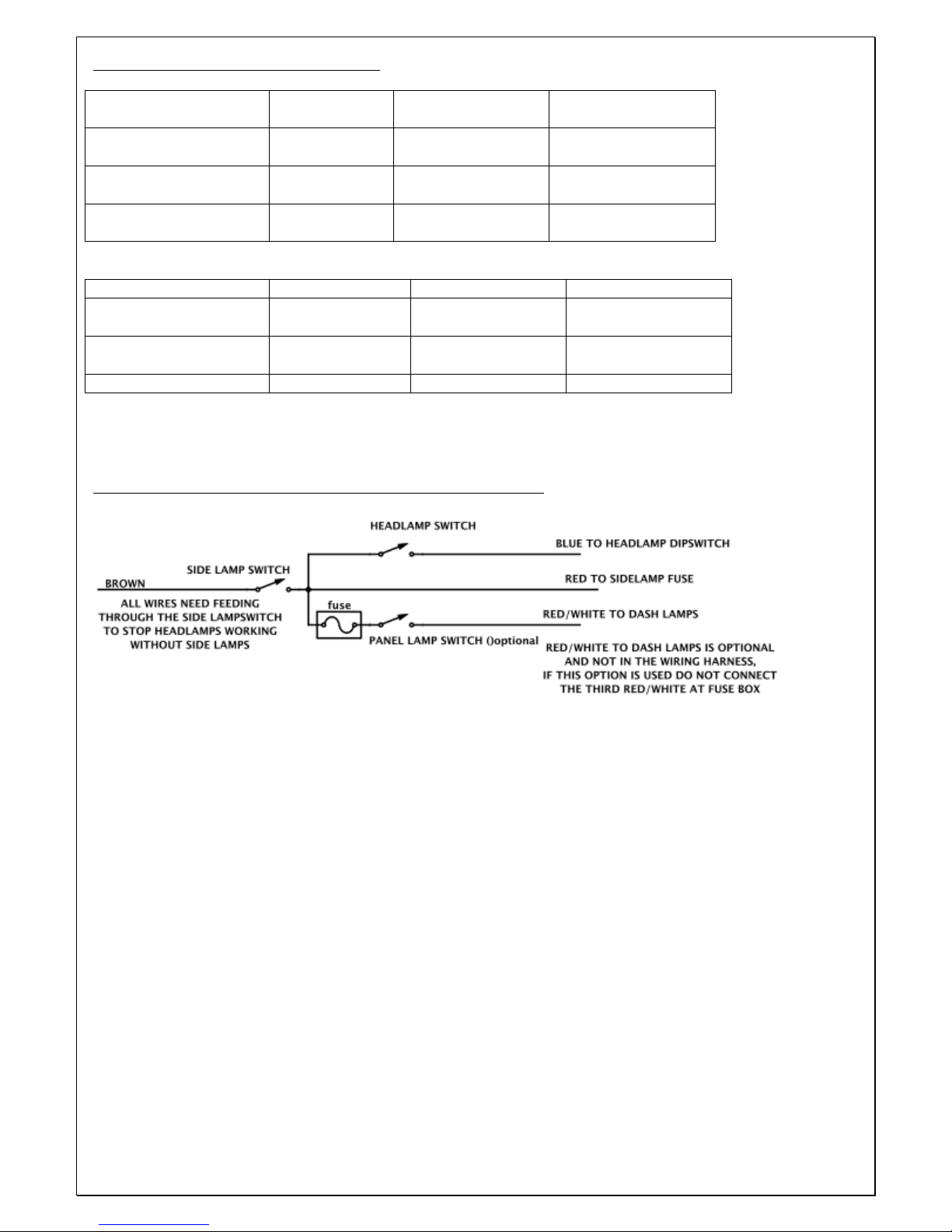
FUSE SIZES AND EXAMPLE LAYOUT
RIGHT MARKER
LAMPS
2x
RED/WHITE
5 AMP
RED
LEFT MARKER
LAMPS
2x
RED/BLACK
5 AMP
LINK TO ABOVE
FUSE
MAIN BEAM LAMPS
3x
BLUE/WHITE
15 AMP
BLUE/BLACK
DIPPED BEAM
LAMPS
2x BLUE/RED
10 AMP
BLUE/ORANGE
IGNITION FEEDS
4x GREEN
10 AMP
WHITE
FUEL PUMP
WHITE/PURPLE
10 AMP
LINK TO ABOVE
FUSE
OVERDRIVE
YELLOW
7.5 AMP
LINK TO ABOVE
FUSE
HORN/MAP LAMP
PURPLE
10 AMP
BROWN
Supplementary head/side/panel lamp switch wiring diagram
Page 31

31
Drill this hole to 25mm for
wiring harness to fuse
boxes and regulator
Drill these four holes and insert
nutserts to secure fuse boxes
Drill these two holes and insert nutserts to
secure regulator
Cut out template or trace and cut out your
own, use to position fuse boxes, regulator
and wiring harness holes. Template fits on
right hand of bulkhead, dotted lines
represent lower parts of top hat
strengthening.
Page 32

32
14 Battery tray, battery and cut off switch
Parts required 109,110,111
1. The battery tray (110) fits on the right hand side in front of the drivers switch panel. First you will
need to remove the body-mounting bolt that goes through the chassis rail just ahead of the driver’s
side/switch panel as this is also used to secure the battery tray. Insert the battery tray through the
side panel and lay in place. You may need to trim the edges to suit the shape of the body and to
allow the battery tray to fit in around the fuel and brake lines. Once settled in place, mark the hole
where the body mount goes through the chassis on the battery tray before removing the tray and
drilling to the appropriate size. Replace the tray and refit the body mount bolt securing the battery
tray at the same time.
2. The battery tray needs to be secured on the front edge with either pot rivets or Rivnuts and screws.
3. Next choose a suitable position for the battery cut off switch (109) either in the top of the driver’s
switch panel or hidden behind the dash panel. Mount the switch securely and make sure there is
nothing that can touch on the terminals of the switch.
4. With the switch mounted you can position and connect the main power cables (111).
5. There are two black cables. One has two eyelets and this connects between the gearbox/overdrive
and the chassis, which can be bolted to the gearbox mounting plate. The other has the negative
battery terminal on one end and an eyelet on the other, the latter needs connecting to the chassis
using the bolt hole in the centre of the driver’s switch panel mounting flange which should have been
left out and drilled out to accept a 5/16 UNF bolt washer and Nyloc. Fit the eyelet on the side away
from the battery and have the cable trailing back and into the battery location. The battery terminals
will need to reach into the driver’s side compartment to allow you to be able to connect them later.
6. There are three main red cables. Take the cable with the positive battery terminal; leave this
terminal in the battery location and connect the other end on the battery cut off switch. Next take the
cable, which has two different size eyelets and connect the larger one on the spare terminal of the
battery cut off switch. Along with this cable connect up the main wiring feed cable (this is the thick
brown (wiring section U)). The other end of this cable needs to pass through the bulkhead and
connect onto the starter solenoid on the engine side of the bulkhead.
7. Connect this wire one end; the last main red wire to the spare terminal on the bulkhead solenoid.
The other end of the third cable connects on the top terminal of the starter motor solenoid.
Connecting the cables like this will make the bulkhead solenoid work as a junction and will also
work as a starter button under the bonnet, as in the original cars.
15 Rear body and door/s
Parts required 150 (inc 152), 146-8
1. With the wiring harness in place the rear body section (150) can now be fitted. Start by making sure
the rear of the fuel tank straps are loose enough to allow the tank to move around so that the neck can
be centralised in the rear body aperture. Also place a length of wood (or similar), which is a little
wider than the rear frame, underneath the rear frame towards the back and support on axle stands or
G clamp to the chassis. This gives the rear body something to sit on until you are ready to fix it in
position. As with the centre section, it is easier for two people to lift and position the rear body,
making sure the alloy panels behind the driver and passenger are correctly aligned. Secure with the
two M6 screws in the centre, two M5 screws behind the driver’s door aperture and eight M5 screws
on the passenger side between the centre and rear body sections (unless a two door model is being
built). Before finishing fitting the rear body the door/s (146) must be fitted to ensure an even panel
gap. The rear of the body can be raised or lowered a small amount to adjust the door/s gap size.
2. The door hinges are not handed but do have an upper and lower. The lower hinge has the stud hole
closer to the hinge pin due to the shape of the door. Cut suitable gaskets to fit between the hinges
and the body/doors. It is easier to fit the nut which is located inside the door panel first as the door
can be laid on a soft cloth on a bench and the hinge can be turned instead of the nut which makes it
easier to start. Fit the stud and nut, which goes in the door gap. Leave these all slightly loose until
the door is fitted and gaps adjusted.
Page 33

33
3. Next offer the door/s to the body and pass the hinge studs through the body. On the inside of the
hinge studs fit on star washers (these help the hinges grip to the body) followed by the plain washers
and Nyloc nuts. Adjust the front and lower door to body gap before tightening the four nuts on each
hinge. With the doors secured to the body centre section and the gaps correctly adjusted, lower and
raise the rear of the rear body section to set the door gaps at the rear of the door/s making sure that
the doors open and close without rubbing on the rear body. The bolts in the centre can also be
released if necessary to allow a small amount of sideways movement to help align the door/s to the
body.
4. Once you are happy with the position of the rear body and the door/s, the rear body can be secured to
the centre body alloy panels at the rear of the door’s apertures with either pot rivets or slot headed
screws and nuts in good equal spacing as these will be visible when finished. The rear body alloy
inner panels also need securing to the rear frame along the lower angle section, the diagonal angle
section and the vertical angle section under the fuel tank with equally spaced pot rivets. These lower
and vertical angles also seal the boot so need a rubber or foam strip or a bead of silicone laid on
before securing. The rear support can now be removed. Next the fuel tank neck can be centralised in
the rear body aperture and the fuel tank straps tightened down fully. Once you are happy with the fit
of the rear body and door/s the door latch and catch (147) may be fitted. Adjust and shim where
necessary to allow the door to sit level with the body before fitted the door rubber and/or foam seal
(148).
16 Rear valance and spare wheel cover
Parts required 151,154
1. Before fitting the valance (151) bond a rubber strip along the top horizontal face of the rear valance.
This will seal the valance to the rear body and give the boot lid a rubber seal to sit on. The rear
valance can now be secured to the rear body with the four M4 bolts supplied and can be riveted
through the belly pan into the rear frame. Finish the rear valance by trimming and locating the rear
valance end caps (may already be fitted to valance) and rivet in place. Seal any small gaps with
sealing tape or silicone sealer.
2. Next take the spare wheel cover (154) and find the turn fasteners, these 2 winged fasteners come
with 2 plastic washers each. Fit one washer on each before passing through the boot lid and fitting
on the second washer. The first washer protects the boot lid from the fastener rubbing and the inner
washer stops the fasteners from falling out when the boot lid is removed. Trial fit the boot lid to
ensure the two lower pins and the top fasteners line up with the positions in the body and adjust the
position of the rear valance or file holes a little if necessary. When you are happy with the fixing
positions fit the two spring catches on the inside of the rear body lip, these will need small washers
fitted as spacers to adjust the position of the spring for fitment of the boot lid. If the boot lid is too
loose fit extra washers to pull in the boot lid until it lines up with the rear body. Now remove the
boot lid and stick on the foam seal on the inside edge of the boot lid, but not along the lower edge as
this is sealed by the rubber strip along the valance.
17 Rear lamps
Parts required 099-102
1. To aid positioning of the rear wiring harness start of by fitting the number plate lamp (102) (this will
centralise and locate the wiring harness). The base of the lamp should be approx 25mm above the top
of the boot lid. Use the rubber base as a template to position the holes to be drilled for mounting and
wiring. The number plate lamp can now be mounted and wired. Use one of the mounting bolts to
secure the wiring inside the boot with a P clip. If you are having roundels and want to fit a rear lamp
for these then you will need an extra lamp the same as the number plate lamp. This can be wired in
with the number plate lamp but will need a hidden switch in the boot, as the lamp cannot be used for
driving on the road.
2. The wiring harness can now be taped to the underside of the rear body towards the rear lamps. Drill
and grommet holes in the rear side panels to get the wires from the boot to the stop/tail lamps (099).
Page 34

34
These lamps can now be wired up according to section 13. The rear indicators (100) are fitted on
angled alloy brackets that mount on the rear inner side panels just below the rear body so are discreet
and don’t need holes drilled in the body. Rear reflectors (101) could also be fitted in the same way to
save spoiling the rear body’s smooth lines.
18 Bonnet
Parts required 128 (inc129,130),131,132,134/5/6,063
1. Now the bonnet (128) can be fitted. Start by bolting on the four hinge plates (131) at the front of the
bonnet. Fit one either side of each bonnet alloy inner panel and secure with four M6 bolts in each.
With the help of at least one other person lift the bonnet and whilst holding in the upright position
offer it up to the chassis and slide through the main 7/16 UNF hinge bolts from the inside to ensure
the hinge plates are not sitting on the threaded part of the bolts. With the bonnet secured by the main
hinge bolts gently lay the bonnet to the centre body section whilst carefully watching to make sure it
doesn’t catch anywhere. If you find it doesn’t fit correctly loosen the eight M6 bolts and re-lay the
bonnet again, then tighten once the bonnet is sitting correctly. If necessary file the holes for the M6
bolts to allow more movement. Once happy with the bonnet position, the side catches (135) can be
loosely fitted to the bonnet with the screws provided. Next pass through the bonnet release handle
(with escutcheons already fitted); secure with the nut and washer provided before tightening the
main catch screws. Mount the latch on the centre body; use a rubber sheet or alloy plate spacers
between the latch and the body to adjust the height of the catch and to line the bonnet up with the
body.
2. Once happy with the fit mount the bonnet stops (136) to the rear inner arches on the inside of the
alloy panels so that once the bonnet is shut they rest on the centre body section which takes some of
the weight of the bonnet. You can now fit the two leather straps (134) that hold the bonnet from
tipping too far forward when open. Bolt one end to the radiator with the radiator stay. The other end
bolts to the bonnet alloy panels that close beside the radiator. To decide on the position to mount
these on the bonnet, tip the bonnet forwards until it’s in a position where it will pull against the
straps making sure the front will not catch on the floor - then drill and bolt this end of the straps.
Finally fit the rubber strip along the return of the centre body, which protects the bonnet from
rubbing.
3. Now that the bonnet is in place it is a good time to set the radiator in an upright position making sure
there is clearance between it and the bonnet when closed. Keeping it in this position mark and drill
mount holes for the radiator stays (063) and these can then be bolted in position.
4. The radiator also has a 3-part set of alloy ducting (132), which can be fitted at this stage. Lay the
lower panel in place before setting the upright panels in place. Drill and rivet the lower part of the
sides through the lower panel and into the front chassis sub frame. Fix the upper parts of the side
panels into the angle section of the front sub frame.
19 Front lamps
Parts required 097/8,137
1. To fit the front lamps (097) start by dismantling the headlamp units and taking the plastic headlamp
retaining ring. Offer it to the bonnet from the front to attain if any edge trimming is required. Trim
or sand if necessary to enable the retaining ring to sit flush in the headlamp position in the bonnet. If
this plastic retainer is the ‘bucket’ type, the rear of this can be cut off to allow access to the bulbs
when fitted as the bonnet has its own cover panel. The retaining ring can now be bolted into place
followed by reassembling the headlamp unit in place in the bonnet. Once the headlamp is in decide
on the position of the indicator lamp (098) (this is sometimes also the side lamp). This should be
fitted in front of the headlamp central in the scalloped headlamp area and central front to back
between the headlamp and the headlamp perspex cover (137), which can be fitted shortly (see
section 20.2). Lay on some masking tape before marking and drilling your mounting hole. The lamp
can now be mounted and the cable from this and the headlamp can be run inside the bonnet cavity
Page 35

35
down to and through the smaller hole, which should be fitted with a grommet. The wires can be run
up the front frame to the junction box and joined according to the wiring instructions on page 19.
20 Interior fittings
20.1 Interior floor and side panels
Parts required 164,165
1. The first interior job is to install the optional inner floor pans (165). Before you lay these in the car
we would recommend fitting sound deadening sheets on the underside to stop the panels resonating
(floor pans are handed, the longer one being for the driver’s side). Make sure they are pushed out as
close to the chassis side rails as possible and if necessary trim to suit. Before fixing in place hold in
the upright side panels (164) inside the side chassis rails and ensure the alloy panels meet nicely with
no big gaps. A rubber seal or ‘u’ section rubber can be used if necessary these may also need a small
amount of trimming. When happy with the fit, from the underside of the car mark the four positions
each side for the seat mounting bolts (if these are not drilled see section 19.4 for hole positions).
Remove all the panels and drill clearance holes in the floor pans before laying the floors and side
panels back in for a final position check. You can remove the side panels and rivet or screw the floor
pans to the outside chassis rail, ideally behind the position of the side panels so they don’t show (this
is to stop them moving in towards the centre of the car). The side panels can now be fitted back in
again. We would suggest screwing them into the top rails and down the front edge with slot headed
screws, as these might have to come off on occasions to access exhaust mounts or pipes and
electrics. The driver’s side panel is made in two sections to gain extra foot space for the driver. The
front part can be fitted first using the body mounting flange at the front end either sharing or adding
fixings; this panel does not need to be removable.
20.2 Gearbox and prop shaft covers
Parts required 157,162
1. If using alloy floor panels as fitted in 19a these should have a return on the inner edge standing
upwards, this is for mounting the tunnel and gearbox cover (157). Start by preparing the gearbox
cover (see diagram on page 34). The lower flange on the tunnel and gearbox cover will need
removing to a level with the vertical section and we advise you drill several access holes for
checking oil etc. You will also need to cut holes for the gearstick and handbrake to pass through the
gearbox cover using the diagram on page 34 as a guide. Once prepared lay the tunnel in the car over
the gearbox. It is easier with the handbrake on and in fourth gear. You will need to stretch the tunnel
apart and over the two floor flanges, as they are made as narrow as we can to keep as much
passenger space as possible. We recommend that you screw or use Rivnuts to secure the tunnels
bearing in mind that you may need to remove them for access to the oil filler etc. Once the gearbox
cover is in place do the same with the prop shaft tunnel. The tunnel should butt up against the
gearbox cover and can be sealed with tape.
2. Once happy with the fit of the two covers they can be trimmed with the supplied ‘Hardura’ trim kit
(162). Start by fitting the gearstick gaiter. Slide this over the gearstick and open the lower end up
before sticking in place with spray impact adhesive. You can then glue on the two part cover that
goes over the gearstick tower on the gearbox cover. There is a half circle that locates on the rear of
the gearstick tower and an oblong piece that fits across the top and down both sides. With these in
place the main tunnel covers can be fitted starting with the parts nearest the front and work your way
back to the large cover, which may need the handbrake slot cut. With the gearbox covers fitted next
glue on the prop shaft cover trim before using the last piece of trim to cover the join between the
front and rear sections this piece can be held down with screws in the front and rear lower corners.
20.3 Seat belts
Parts required 160
Page 36

36
1. We advise using a three-point harness; there are mounting points built in the chassis for this. The
outer lower mounts are bolted directly to the chassis, the inner mounts are bolted on to an angle
bracket first to bring them out to match the position of the outer mounts. This angled bracket is then
bolted to the rear bulkhead. The upper mounts are also in the rear bulkhead central to each seat. All
positions in the chassis have 1/2 UNF nuts welded in place ready to accept the fixing bolts supplied.
As the seat belts are bolted in place you must check now that they are not twisted as this will
compromise their safety and make them uncomfortable to wear.
20.4 Seats
Parts required 158/9
1. If the seat mount holes are not drilled you will need to drill four holes for each seat, starting with the
rear mount holes, which need to be in the front edge of the rear bulkhead horizontal panel just behind
the small return. The outer hole centres need to be three inches from the square box chassis section
and the inner hole centres need to be thirteen inches in from the outer hole centres. The front holes
need to be in perfect parallel with the rears and thirteen inches forward, this will put the inner hole in
the inner chassis rail and the outer in the seat brace bar from the outer chassis rail to the chassis cross
brace. If you need the seat to sit as low as possible and do not need the seat to move forwards and
backwards then the seats can be bolted directed down to the floor, otherwise first bolt down the seat
runners (159) with the 5/16” UNF bolts supplied before bolting in the seat (158). The seat base will
require drilling to mount. The easiest way to mark the seat is to take some old bolts that fit the
runners and cut the heads off before grinding to a point. These can then be screwed into the seat
runners before laying the seat in place. Leaning on the seat will then put a mark on the underside of
the seat where fixing holes are required.
21 Exterior fittings
21.1 Bonnet Straps
Parts required 139
1. To finish the bonnet it needs two leather buckle straps (139) on the top face with the centre of the
strap approximately 6 inches from the side of the body. Protect the bonnet and scuttle with masking
tape then lay the buckle end on the scuttle with the leather finishing at the scuttle edge as if it
overhangs (it will make closing the bonnet awkward). With the position confirmed mark the two
holes in the strap on the body then remove the strap and carefully drill. You can then remove this
side of the masking tape and secure the strap with fixings (supplied).
2. Next take the other end of the leather strap and insert the end into the buckle. Select whichever hole
makes the strap length most similar to the length on the buckle/body side. With the strap in the
buckle but not pulled so tight it can’t be released once it is bolted down, and when you are happy
with the position, mark the two holes in the end of each strap onto the masking tape then remove the
strap and carefully drill the holes before removing the masking tape and securing the straps with
bolts provided.
21.2 Headlamp covers
Parts required 137
1. To fit Perspex headlamp covers (137) you will need to take time to file them to get the outline
correct, shaped to fit your bonnet. The headlamp covers are handed and only fit one way up. Protect
the body surrounding the headlamp cover indent and put one pen line at the top as a constant
reference point. Take the headlamp cover and a pen suitable for temporary marking on plastic and
lay the cover over the headlamp cover position, turn forwards and backwards until you find the best
fit with the profile of the body to cover. Mark the top of the cover in line with the line on the body;
this is a reference so every time you bring back the cover it will go back in the same place. Carefully
Page 37

37
draw on the cover where it will need small amounts of filing to suit the body indent and bit-by-bit
file or sand the cover to fit whilst checking regularly. Once the shape is correct lay masking tape on
the body where the mounting holes need to be drilled. Now offer up the cover and mark the
positions before removing the cover and carefully drilling the screw holes. Then remove all tape,
clean up and fit the covers with the screws provided.
21.3 Front Grille
Parts required 140
1. The front grille (140) is held in by six M5 nuts on the rear of the grille. The bonnet will have holes
or indents in the required locations. Supplied with the fixings are six Nyloc nuts and six plain
washers, the washers will need flats ground on them to ensure they don’t over hang on the inside of
the grille, which is so visible from the front (this may already be done for you).
21.4 Front Screen
Parts required 143/4
1. If your body is not being painted by Suffolk Sportscars you will need to prepare the screen plinth
(143) before painting by drilling in the required mounting holes. In the body mounting side you will
need eight fixing positions, start by marking each end central to the lower flange approx one inch
from the end then measure the distance between the two marks and divide into equal sections for the
remaining six fixings. Next mark the top flange that holds the Lexan Perspex screen (144) for seven
fixings, one between each pair of lower flange fixings. Once marked drill all holes as 5mm to suit
2BA fixing screws; clean off any burrs and sharp edges and your plinth is ready for the paint shop.
2. To fit the screen, start by protecting (if painted) the relative body area before laying the plinth on the
car. The inner edge needs to be five inches from rear edge of the scuttle panel to give room for the 2
Brooklands screens and the rear view mirror. This should leave the plinth approx two and a half
inches forward of the door/rear body join. With the plinth laid in the correct alignment and central to
the body offer up the Brooklands screens to confirm enough space has been left then mark the eight
body mounting positions before removing the plinth and carefully drilling the 5mm mounting holes
into the body. The tape can now be removed and the plinth secured to body with the 2BA screws
and Nylocs provided.
3. Next take the Lexan Perspex screen and protect the lower mounting edge with tape before inserting it
into the plinth mounted on the body. Mark the seven fixing positions before removing to drill the
holes. Take great care when drilling the Perspex as it can crack very easily. Use an off-cut of wood
behind the Perspex to ensure you do not shoot through too fast as this can crack the screen. Once
drilled and cleaned it can then be slid back into position and secured with the 2BA screws and
Nylocs.
21.5 Brooklands Screens and Rear View Mirror
Parts required 145,120
1. As with the main screen protect the fixing area of the Brooklands screens (145) before marking a line
in the area that the screens fit 15mm from the rear edge of the scuttle panel. This is the fitting line
for the Brooklands screens. You can then offer up the screens and centralise them both to the lower
cut part of the main Perspex screen before marking and drilling the mounting holes. Next mark a
line in the centre of the dashboard for the rear view mirror (120) 40mm back from the rear edge of
the scuttle. Measure to find the centre of the body, which should also be the centre between the
Brooklands screens. Offer up the mirror to make sure the location is correct as different mirrors are
set at different angles, then mark the mount positions before removing the mirror, carefully drilling
the mounting holes and removing the tape from the area behind the main screen. You can then clean
the area up before mounting the Brooklands screens and the mirror.
Page 38
38
TRANSMISSION COVER PREPARATION GUIDE
A = STARTER MOTOR UPPER ACCESS HOLE - Ø40mm
B = STARTER MOTOR LOWER ACCESS HOLE - Ø40mm
C = O/D SWITCH ACCESS HOLE – Ø50mm
D = OIL FILLER / LEVEL ACCESS HOLE – Ø50mm
E = HANDBRAKE SLOT
Note: All dimensions in millimeters.
1. REMOVE BASE FLANGE
2. TRIM REAR SECTION TO SAME ANGLE
AS CHASSIS FOOT PLATE.
Page 39

39
22 Finishing Items and Extras
22.1 Wheels and Tyres
Parts required 045-8
1. If your wheels (046) have been painted it is very important to remove any paint from the internal
splines and the internal taper which meets with the hub and the external taper, which meets with the
spinner. Failure to do this can cause a wheel to seize preventing removal or can cause a spinner to
loosen whilst driving.
2. Grease the splines and tapers on each hub before fitting the wheels and then grease the internals of
the spinners (045) before fitting. Note that the right hand hubs are left hand thread and the left hand
hubs are right hand thread. Tighten each spinner by hand followed by the hide end of the mallet.
(The spinners are marked with direction; a downward stroke of the mallet on the spinner lug towards
the rear of the car will tighten them).
22.2 Tonneau cover
Parts required 166
1. To fit the tonneau cover (166) start by laying protective tape around the edge of the driver/passenger
compartment before getting an assistant to help lay the cover in position and assess how much of the
edge covers the body and work out how far from the edge to mount the snap fixings. You will want
them central in the stitched edge around the cover to look best; this is usually about one inch from
the edge. Once established mark a line all around the body aperture one inch from the inner edge;
this is the line on which to fit the snap fixings to the body. Start by marking the snap positions on
the door/s one inch from each end or the equivalent position on the opposite side if single door
model, with a third position marked centrally between them. Take the measurement between the
snap fixing positions and use the closest multiple to mark out even spaced positions around the rear
of the passenger compartments. Next mark positions adjacent to the Brooklands screens mounts for
snap fixing. You will need one either side of each mount making sure you don’t put them so close
that you can’t get a snap fixing in the tonneau cover.
2. Once all the positions are marked and you have checked the tonneau will cover all positions
carefully drill all positions with a 3mm drill bit. Now you are ready to remove the protective tape
and start fitting the snap fixings. The male part is to be riveted on the body; this is the half which
outer rim sits flat on the body with the centre protruding upwards. Before starting to rivet on the
fixings make sure the end of your rivet gun fits far enough into the snap fixing to pull up tightly. If
the rivet is loose between the snap fixing and the gun head find a suitable spacer to take up the gap
then rivet on all the male snap fixings to the body.
3. With the males all fitted, get an assistant to hold the tonneau cover in place at the front where the
cover goes in and out of the Brooklands screens mounts to get the cover central; it should also fit
nicely over the steering wheel. Pull the cover evenly and not over tight but enough not to make it
baggy. Once happy mark the two outer most holes in this front section. The easiest way to mark the
cover is to stick a small piece of masking tape to the underside of the tonneau cover then with the
cover in position push down firmly over the snap fixing and this will leave a indented ring on the
tape. The centre of these marks can then be punched out to allow the female part of the snap to be
fitted. Take the cover to the workbench where you can use the tools provided to mount the female
part on the inside of the tonneau with the chrome cover side on the outside.
4. With the first fixings fitted return the cover to the car and attach with the first two snaps. Next pull
the cover evenly over the cockpit and mark the two rear outermost snap fixings in the same way as
the first two then return the cover to the bench to fit these snaps before once again returning to the
car and fitting to the car with four fixings.
5. With the cover now held in place gradually pull the cover over the car and add snap fixings until they
are all fitted and the cover fits the car, take time to ensure the cover fits as smoothly as possible.
Page 40

40
SECTION 1 Chassis / Suspension / Brakes
NOTES!
Customer
Location
Estimated date of delivery
DESCRIPTION
Strip/prepare/paint donor components
001
001a
Chassis inc. front & rear subframes, engine brace, prop shaft hoop & gearbox bracket.
Alloy Belly Pan panel set (9 piece)
002
Paintwork to chassis
003
Front upper wishbone cross brace bars x 2
004
Fr Lower wishbones x2 LH & RH
005
Fr Lr wishbone pivot shafts, nuts & pins x2 + 8 serrated washers
006
Fr Lower wishbone tie bars x2 + tubes x2
007
Fr Lr wishbone polybushes x4
008
Fr Lr front balljoint x2
009
Fr Upper front wishbones x2 pairs
010
Fr Upper wishbone polybushes x4
011
Fr Upper wishbone inner mounting brackets x2 & 16 camber shims
012
Fr Upper balljoints x2 & castor shims x6
013
Fr Uprights and Stub Axles, washers, nuts & pins x 2
014
Fr Front Splined MK2 Hubs x2
015
Fr Bearing kit to suit stub axles
016
Fr Torsion Bars x2 “E type” (handed)
017
Fr Torsion Bar tear drops x2 and adjustors
018
Fr Front Brake Calipers & Pads & bolt kit
019
Fr Front Discs x 2
020
Fr Anti Roll Bar + D brackets & polybushes x2
021
Fr Anti Roll Bar Drop Link brackets x2 & bushes x4
022
Fr Steering Rack w/track rod ends & extensions
023
Fr Steering Rack mounting brackets
024
Fr Steering Control Arm x2 LH & RH
025
Fr Collapsible Steering Column + spacers
026
Fr Lower Steering Column Shaft & Knuckle joints x2
027
Fr Dampers x2
028
Rr Prop Shaft
029
Rr Axle live w/ caliper brackets, woodruff keys + castle nuts (Ratio , LSD or open)
030
Rr Splined MK2 Hubs x2
031
Rr Brake calipers & pads x2 + fixing bolts + handbrake calipers & pads
032
Rr Brake Discs x2
033
Rr dampers x2 & rear springs x2
034
Rr Radius Arms complete w/front & rear bush brackets x2 sets
035
Rr Radius Arm polybushes (front & rear)
036
Rr Radius Arm to chassis castle nuts, washers & pins x2
037
Rr Tie bars w/bushes + rose joints x2
038
Rr Panhard Rod w/bush + rose joint
039
Brake Lines car set + 2way connector x3 + brake light switch
040
Brake Master Cylinder + bottle & servo (optional) + hose & fixings Servo Y / N
041
Brake & Clutch flexi hoses x4
042
Clutch Master Cylinder + bottle with clevis connector, etc.
043
Pedal box set complete w/pedals x3 etc
044
Handbrake, cable set x3 & Diff pivot assy
045
Chrome Jaguar spinners LH x2, RH x2
046
Wire Wheels – 16” 72 spoke 5J x5 Colour- 60 spoke option Y / N
047
Blockley Tyres 600 x 16, Blockley tapes & inner tubes x 5 Crossply or Radial option
048
Fitting tyres to wheels & balancing
049
Nuts & bolts kit, complete car.
Delivery Diesel or courier costs: Date:
Any items not ticked in the SUPPLIED column are out of stock and will follow ASAP.
Page 41

41
SJ REF No.
SUPPLIED
REQUIRED
SECTION 2 Engine and Gearbox
!
NOTES!
Customer
Location
Estimated date of delivery
DESCRIPTION
052
Engine Jaguar XK / XJ donor/ VSE
Engine size : spec :
053
Engine mounting rubbers x2
054
Engine mounting brackets x 2 + Rear steady bar, brackets and bushes
055
Alternator or Dynamo bracket + adjuster
056
Alternator or Dynamo
057
Fan belt – 925 or 975
058
Starter motor inertia /pre-engaged
059
Starter solenoid
060
D type Plug Lead Holder, Plug leads, Extra long king lead.
061
Hoses .. car set
062
Radiator alloy C type replica + 15lb Cap + overflow hose
063
Radiator Stays + fitting kit
064
Electric Fan
065
Fan controller switch (built into radiator)
066
12v Sports Coil
067
Distributor (fitted to engine) Points or Electronic
068
Carburettors–twin HS8 SU’s or Triple Weber with Airbox&filter or Trumpets
069
Inlet Manifold to suit carbs + thermostat housing
070
Throttle linkage to suit carbs
071
Choke cable to suit carbs
072
Exhaust Manifolds x 2 + gaskets x4 & Alloy body shield Stainless option Y / N
073
Exhaust Pipes x2 + Twin Silencer + brackets, clamps, 3 cotton reels
074
Cam covers. alloy smooth type (fitted to engine) __Badges __Breathers
075
Oil Filler Cap on cam cover Jaguar alloy (fitted to engine)
076
Oil Filter assembly (fitted to engine)
077
Oil Catch Tank (Weber only) + flex alloy Pipes
078
Flywheel (fitted to engine)
079
Gearbox type Gearbox overhaul
080
Gearbox mounting rubber + adaptor
081
Gearbox Lever + Knob
082
Overdrive
083
Modified Bell housing + lower cover
084
Clutch Assembly + driven plate (fitted to engine)
085
Clutch Fork & carbon thrust
086
Clutch Slave Cylinder + banjo connector
087
Fuel Tank (alloy) 25 gal
088
Fuel Tank mountings
089
Fuel Pipe kit inc. braided hoses + clips
090
Fuel Contents Sender
091
Fuel Pump & filter
092
Water pump w/pulley (xj6) and Single (narrow fit) crankshaft pulley
Delivery Diesel or courier costs: Date:
Any items not ticked in the SUPPLIED column are out of stock and will follow ASAP.
Page 42

42
Any items not ticked in the SUPPLIED column are out of stock and will follow ASAP.
SJ REF No.
SUPPLIED
REQUIRED
SECTION 3 Electrical Fittings / Instruments
!
NOTES
Customer
Location
Estimated date of delivery
DESCRIPTION
093
Wiring Loom – braided
094
Fuse Boxes x2
095
Control Box - Alternator
096
Control Box - Dynamo
097
Front Headlamps x 2 + mountings x 2
098
Front indicator Lights x 2
099
Rear Light stop/tail x 2
100
Rear Indicators x2 + brackets or special brake lamp/flasher relay **
101
Rear Reflectors x 2
102
Rear Number Plate light
103
Instrument Set (rev, speedo, oil/water, amps, fuel)
104
Speedometer Cable + 90° drive
105
Ignition switch + Starter button
106
Warning Lights x 3
107
Indicator switch
108
Horn button
109
Battery cut out master switch
110
Battery tray (battery available at request)
111
Battery Cable set
112
Spark plug holder
113
Alloy Switch Panel
114
Headlamp Dip switch
115
Horns, original rebuilt or new replicas
116
Under bonnet Light with bracket
117
Map reading Light
118
Grab handle passenger
119
Steering Wheel + boss Growler fitted to centre Y / N
120
Rear view Interior Mirror with bracket
121
Side mirror offside + (nearside Y / N )
122
Panel, side & headlamp switches With Alloy knobs Y / N
123
Map & bonnet switches
124
Fuel pump switch
125
Overdrive switch
126
Headlamp wiring junction boxes x2
127
Other items:
** Brake lamps can only be used as flashers in certain countries or with early donor cars in uk.
Delivery Diesel or courier costs: Date:
Page 43

43
SJ REF No.
SECTION 4 Bodywork / Fittings / Interior
!
NOTES
Customer
Location
Estimated date of delivery
DESCRIPTION
128
!"##$%&'$(%)"#&*+,&-&.//"0&12#$/3&&&&&&&&&&&&&&&&&&&&&&&,2#$/3&4)%%$5&&&6&7&8&
129
Ducting for Carburettors or Bonnet Scoop (with rain catcher)
130
Louvered Panels in alloy (top x 2, side x 2)
131
Mounting Hinge bracket (Chassis to Bonnet)
132
Alloy Ducting for Radiator x 1 set (4 parts)
133
Alloy Headlamp Cowling covers + wiring blanks x2
134
Bonnet opening stay straps x 2
135
Bonnet Latches, Catches + Chrome Turn Handles x 2
136
Bonnet Stop Brackets & Rubbers x 2
137
Headlamp Perspex covers x2
138
Jaguar Bonnet Badge ( bronze Growler)
139
Bonnet top security straps & buckles x 2
140
Bonnet Grille
141
Centre Section GRP 1 or 2 Door Panels fitted Y / N
142
Alloy panels & Bulkhead / Firewall (total 15no. items)
143
Windscreen mounting plinth
144
Windscreen (full width Lexan Perspex) type - High/low
145
Brooklands Aeroscreens x 2
146
Door offside + hinges Door nearside + hinges Y / N
147
Door inner Handle, latch + catch 1 or 2
148
Door trim Rubber Seal 1 or 2
149
Instrument binnacle + dash panel (alloy)
150
Rear Body Section GRP and Alloy panels Panels fitted Y / N
151
Rear valance
152
Alloy panels sections behind seats
154
Spare Wheel Cover + Wing fastener kit x 2 + spare wheel leather strap
155
Aston Fuel Cap & adaptor + alloy mounting plate to body + hose
156
Rear Jaguar Badge
157
Interior - GRP Gearbox Cover + Transmission cover
158
Seat buckets x 2
159
Seat Runners x 2 (1 pair)
160
Seat Belt Harness sets x 2 black, Some colour options available
161
Leather/carpet Upholstery to seats Base type Soft / firm Colour-
162
Hardura Upholstery to transmission covers standard black Silver option Y / N
163
Vinyl covers for dash & Instrument binnacle in Black, leather dash option Y / N
164
Alloy Interior side panel set + pannier lids locks
165
Alloy Interior floor panel set
166
Tonneau Cover + fittings LHD or RHD
167
Black hardura for inside panniers
168
Paintwork by Suffolk Sportscars approved Paint shop.
169
Delivery to/from paint shop
170
Registration No. Plates - front & rear (self adhesive plastic)
171
Chassis plate - stamped
172
Racing spots on bonnet/doors, painted only, colour?
Delivery Diesel or courier costs: Date:
Any items not ticked in the SUPPLIED column are out of stock and will follow ASAP
Page 44

44
C"type'Hardware'list'
No
Item
Qty
Width
Length
Thread
Type
Notes
001
Front frame
2
5/16
1
Unf
Hex head
2
5/16
Unf
Nyloc nut
4
5/16
Unf
Plain washer
Rear frame
2
3/8 1 Unf
Hex head
2
3/8 Unf
Nyloc nut
4
3/8 Unf
Plain washer
2 7/16
3
Unf
Hex head
2
7/16
Unf
Nyloc nut
4
7/16
Unf
Plain washer
Engine Bay Brace
8
5/16
1
Unf
Hex head
8
5/16
Unf
Nyloc nut
16
5/16
Unf
Flat washer
Gearbox bracket
4
3/8 1 Unf
Hex head
4 3/8 Unf
Nyloc nut
8
3/8 Unf
Plain washer
Propshaft hoop
4
3/8 1 Unf
Hex head
4
3/8 Unf
Nyloc nut
8
3/8 Unf
Plain washer
003
C/W 011
004
Front lower wishbones
2
M5
50
Metric
Hex head
2
M5
Metric
Nyloc nut
4
M5
Metric
Plain washer
2
1/2
4 1/2
Unf
Hex head
2
1/2 Unf
Nyloc nut
4
1/2 Unf
Plain washer
006
C/W 004
008
Front lower balljoint
8
5/16
3/4
Unf
Hex head
8
5/16
Unf
Lock washer
009
Upper wishbone
4
9/16
Unf
Half nyloc
4
9/16
Unf
Penny washer
011
Upper wishbone inner
mount
4
1/2 3 Unf
Hex head
4
1/2 Unf
Lock washer
20 Shims
4
1/2 Unf
Plain washer
4
3/8
1 1/4
Unf
Hex head
4
3/8 Unf
Nyloc nut
8
3/8 Unf
Plain washer
012
Front upper balljoints
4
3/8
3 1/2
Unf
Hex head
8 Shims
4
3/8 Unf
Nyloc nut
8 3/8 Unf
Plain washer
017
Torsion bar teardrop mount
8
3/8
1 1/4
Unf
Hex head
8
3/8 Unf
Nyloc nut
14
3/8 Unf
Plain washer
018
Front brake calipers
4
7/16
1 1/2
Unf
Hex head
Cross
drilled
4
7/16
Unf
Lock washer
4
7/16
Unf
Plain washer
As Shims
019
Front brake disc
10
7/16
1 1/2
Unf
Hex head
10
7/16
Unf
Philidas nut
Page 45

45
10
7/16
Unf
Plain washer
020
Anti-roll bar ‘D’ brackets
4
3/8 1 Unf
Hex head
4
3/8 Unf
Nyloc nut
8
3/8 Unf
Plain washer
021
Anti-roll bar drop links
2
7/16
2 1/4
Unf
Hex head
2
7/16
2 3/4
Unf
Hex head
4 7/16
Unf
Nyloc nut
8
7/16
Unf
Plain washer
023
Steering rack mount bracket
4
5/16
4 1/2
Unf
Hex head
4
5/16
Unf
Nyloc nut
8
5/16
Unf
Plain washer
024
Steering control arm
2
7/16
1 1/2
Unf
Hex head
2 7/16
Unf
Lock washer
025
Collapsible column
2
7/16
1 1/2
Unf
Hex head
+2spacers
2
7/16
Unf
Nyloc nut
4
7/16
Unf
Plain washer
2
5/16
2 1/4
Unf
Hex head
2
5/16
Unf
Nyloc nut
4
5/16
Unf
Plain washer
026
Steering shaft knuckles
4
5/16
1 3/4
Unf
Hex head
4
5/16
Unf
Nyloc nut
8
5/16
Unf
Plain washer
027
Front dampers
2
7/16
2 1/2
Unf
Hex head
2
7/16
Unf
Nyloc nut
4
7/16
Unf
Plain washer
+2spacers
028
Propeller shaft
4
3/8 1 Unf
Hex head
8
3/8 Unf
Nyloc nut
029
Rear axle
2
7/8 Unf
Castle nut
2
7/8 Unf
Plain washer
2
4mm
Split pins
+key steel
030
Rear hubs
10
7/16
1 1/2
Unf
Hex head
10
7/16
Unf
Philidas nut
10
7/16
Unf
Plain washer
031
Rear brake callipers
4
7/16
1 1/2
Unf
Hex head
Cross
drilled
4
7/16
Unf
lock washer
4
7/16
Unf
Plain washer
As shims
032
Rear brake disc (c/w 030)
033
Rear dampers
4 ½ 2 1/2
Unf
Hex head
4 ½ Unf
Nyloc nut
8 ½
Unf
Plain washer
034
Rear radius arm
8
5/16
1 1/4
Unf
Hex head
8
5/16
Unf
Nyloc nut
16
5/16
Unf
Plain washer
4
5/16
3/4
Unf
Hex head
4
5/16
Unf
Lock washer
Page 46

46
2
7/16
3 3/4
Unf
Hex head
2
7/16
Unf
Nyloc nut
4
7/16
Unf
Plain washer
036
Rear radius arm
2
5/8 Unf
Castle nut
2
5/8 Unf
Washer
2
4mm
Split pin
037
Rear tie bar
2
1/2
2 1/2
Unf
Hex head
2x 1/2
spacer
2
1/2 Unf
Lock washer
2
1/2 Unf
Plain washer
2
1/2
2 1/2
Unf
Hex head
2
1/2 Unf
Nyloc nut
4
1/2 Unf
Plain washer
038
Pan hard rod
1
1/2
2 1/2
Unf
Hex head
1
1/2 Unf
Nyloc nut
2
1/2 Unf
Plain washer
2
1/2id
1/2
Spacers
1
9/16
Unf
Nyloc nut
1
9/16
Unf
Plain washer
o’d’ 1 1/2
039
Brake line set
3
1/4
1 1/2
Unf
Hex head
1 1/4 Unf
Lock washer
2
1/4 Unf
Nyloc nut
5
1/4 Unf
Plain washer
040
Brake master cylinder
2
3/8 Unf
Nyloc nut
2
3/8 Unf
Plain washer
041
Brake/clutch flexi hose
3
3/8 Unf
Half nut
3 3/8 Unf
Star washer
042
Clutch master
2
5/16
1 1/2
Unf
Hex head
2
5/16
Unf
Nyloc nut
4
5/16
Unf
Plain washer
2
5/16
Unf
Plain nut
2
5/16
Unf
Star washer
043
Pedal assembly
4
5/16
1
Unf
Hex head
4
5/16
Unf
Nyloc
8
5/16
Unf
Plain washer
1
1/4
1 1/2
Unf
Hex head
1
1/4 Unf
Nyloc
2
1/4 Unf
Plain washer
4
3/8
1 1/4
Unf
Hex head
4 3/8 Unf
Nyloc
8
3/8 Unf
Plain washer
044
Handbrake
2
5/16
1
Unf
Hex head
2 5/16
Unf
Nyloc
4
5/16
Unf
Plain washer
2
5/16
Unf
Plain nuts
2
5/16
Unf
Star washer
+ pivot
2
5/16
1
Unc
Hex head
053
Engine Rubber mounts
4
M8
25mm
Metric
Hex head
4 M8
Metric
Nyloc
Page 47

47
8
M8
Metric
Plain washer
2
1/2 1 Unf
Hex head
2
1/2 Unf
Lock washer
2
1/2 Unf
Plain washer
054
Engine mount brackets
6
7/16
1
Unf
Hex head
6
7/16
Unf
Lock washer
Engine rear steady
4
5/16
1
Unc
Hex head
5
5/16
Unf
Lock washer
5
5/16
Unf
Penny washer
1
5/16
1
Unf
Hex head
1
3/8 2 Unf
Hex head
1
3/8 Unf
Plain washer
1 3/8 Unf
Lock washer
055
Alternator bracket
2
5/16
3
Unf
Hex head
056
Alternator
1
5/16
5 1/2
Unf
Hex head
1
5/16
Unf
Nyloc
2
5/16
Unf
Plain washer
Alternator adjuster bracket
1
5/16
3
Unf
Hex head
1
3/8 Unf
Eyed bar
2 3/8 Unf
Plain nut
2
3/8 Unf
Lock washer
1 Mount block
1
5/16
1 3/4
Unf
Hex head
1
5/16
Unf
Nyloc
2
5/16
Unf
Plain washer
058
Starter motor
2
3/8
1 1/2
Unc
Hex head
2
3/8 Unc
Star washer
059
Starter solenoid
2
M5
25mm
Metric
Hex head
2
M5
Metric
Nyloc
4
M5
Metric
Plain washer
063
Radiator fitting kit
2
3/8
1 3/4
Unf
Hex head
2 3/8id
11/8od
Unf
Plain washer
2
3/8 Unf
Plain washer
2
3/8 Unf
Nyloc
4
M6
20mm
Metric
Hex head
4
M6
Metric
Nyloc
8
M6
Metric
Plain washer
066
Coil 2 5/16
1
Unf
Hex head
2 5/16
Unf
Nyloc
4
5/16
Unf
Plain washer
069
Inlet manifold
18
5/16
Unf
Plain nut
18
5/16
Unf
Lock washer
069
Thermostat housing
(webers)
3
5/16
1
Unc
Hex head
3
5/16
Unc
Lock washer
3 5/16
Unc
Plain washer
070
Throttle linkage (SU’s)
2
5/16
1
Unf
Hex head
2
5/16
Unf
Nyloc nut
4
5/16
Unf
Plain washer
2
5/16
1
Unc
Hex head
2
5/16
Unf
Lock washer
072
Exhaust manifolds
16
5/16
Unf
Brass nuts
Page 48

48
16
5/16
Unf
Lock washer
8
3/8 Unf
Brass nuts
8
3/8 Unf
Lock washer
073
Exhaust silencer
6
5/16
1
Unf
Hex head
6
5/16
Unf
Nyloc
12
5/16
Unf
Plain washer
Exhaust stabiliser
2
5/16
Unf
Nyloc
2
5/16
Unf
Plain washer
077
Oil catch tank (Webers
only)
2
M5
50mm
Metric
Hex head
2
M5
Metric
Nyloc
4
M5
Metric
Plain washer
080
Gearbox mount C/W
adapter
1
3/8 Unf
Nyloc
1
3/8 Unf
Plain washer
083
Bell housing
10
3/8 3 Unf
Hex head
4
3/8
1 1/2
Unf
Hex head
14
3/8 Unf
Star washer
6
3/8 Unf
Nyloc
6
3/8 Unf
Plain washer
Bell housing lower cover
4
1/4
3/4
Unc
Hex head
4 1/4 Unc
Star washer
086
Clutch slave cylinder
2
3/8 Unf
Nyloc
2
3/8 Unf
Plain washer
088
Fuel tank straps
4
M6
25mm
Metric
Hex head
4
M6
Metric
Nyloc
8
M6
Metric
Plain washer
2
3/8 2 Unf
Hex head
2 3/8 Unf
Nyloc
4
3/8 Unf
Plain washer
090
Fuel sender
6
5mm
20mm
Metric
Screws
6
5mm
Metric
Lock washer
6
5mm
Metric
Plain washer
091
Fuel Pump and Filter
2
5/16
1
Unf
Hex head
2 5/16
Unf
Nyloc
4
5/16
Unf
Plain washer
094
Fuse Boxes x2
4
5mm
30
Metric
Slot head
4 5mm
Metric
Plain washer
4
5mm
Metric
Nyloc nut
Or rivnuts
095
Control Box
2
5mm
30
Metric
Slot head
2
5mm
Metric
Plain washer
2
5mm
Metric
Nyloc nut
Or rivnuts
097
Front headlamps
8
4mm
25
Metric
Slot head
8
4mm
Metric
Nyloc nut
8 4mm
Metric
Plain washer
099
Rear Light stop/tail
6
3mm
20
Metric
Slot head
6
3mm
Metric
Nyloc nut
6
3mm
Metric
Plain washer
100
Rear Indicators x2 +
6
3mm
20
Metric
Slot head
Page 49

49
brackets
6
3mm
Metric
Nyloc nut
6
3mm
Metric
Plain washer
6
4mm
Pot rivet
101
Rear Reflectors x 2
2
4mm
20
Metric
Slot head
2
4mm
Metric
Nyloc nut
4 4mm
Metric
Plain washer
108
Horn button
2
3mm
20
Metric
Slot head
2
3mm
Metric
Nyloc nut
2
3mm
Metric
Plain washer
109
Battery cut out master
switch
2
5mm
25
Metric
Slot head
2
5mm
Metric
Nyloc nut
4 5mm
Metric
Plain washer
110
Battery tray
3
4mm
Pot rivet
111
Battery Cable set (earth
bolt)
1
5/16
1
Unf
Hex head
1
5/16
Unf
Nyloc nut
2
5/16
Unf
Plain washer
1
5/16
Unf
Star washer
113
Alloy Switch Panel
6
5mm
20
Metric
Slot head
6 5mm
Metric
Nyloc nut
6
5mm
Metric
Plain washer
114
Headlamp Dip switch
2
5mm
20
Metric
Slot head
2
5mm
Metric
Nyloc nut
2
5mm
Metric
Plain washer
115
Horns
2
6mm
25
Metric
Slot head
2 6mm
Metric
Nyloc nut
4
6mm
Metric
Plain washer
126
Headlamp junction boxes
4
5mm
20
Metric
Slot head
4
5mm
Metric
Nyloc nut
4
5mm
Metric
Plain washer
131
Mounting Hinge bracket
8
6mm
25mm
Metric
Hex head
8
6mm
Metric
Nyloc
16
6mm
Plain washer
2
3/8 3 Unf
Hex head
2
3/8 Unf
Nyloc
2
3/8 Unf
Plain washer
2
3/8
1” od
Unf
Plain washer
132
Ducting for Radiator
12
1/8
Pot rivets
133
Headlamp alloy covers
16
1/8
Screws
134
Bonnet opening stay straps
4
6mm
30mm
Metric
Hex head
4
6mm
Metric
Nyloc
8
6mm
Plain washer
135
Bonnet Latch/Catch/Handle
4
5mm
20mm
Metric
Countersunk
4
5mm
Metric
Nyloc nuts
Page 50

50
8
5mm
Metric
Plain washer
4
6mm
30
Metric
Coach bolts
4
6mm
Metric
Nyloc nuts
4
6mm
Metric
Plain washer
+4 spacers
136
Bonnet Stop Brackets
8
M5
20mm
Metric
Pan head
8
M5
Metric
Nyloc
16 Plain washer
137
Headlamp Perspex covers
8
1/8
Self taping
139
Bonnet top security straps
8
6mm
30mm
Metric
Coach bolt
8
6mm
Plain washer
8
6mm
Nyloc
140
Bonnet Grille + fixings
6
5mm
Nyloc
6 5mm
Plain washer
141
Centre Section
GRP
22
8mm
20mm
Metric
Hex head
22
8mm
Metric
Nyloc nut
44
8mm
Metric
Plain washer
bulkhead
7
5mm
20mm
Metric
Slot head
7
5mm
Metric
Nyloc nut
7
5mm
Metric
Plain washer
142
Alloy panels, centre section
20
5mm
25mm
Metric
Hex head
20
5mm
Metric
Nyloc nut
20
5mm
Metric
Plain washer
143
Windscreen mounting plinth
9
5mm
30mm
Metric
Slot head
9
5mm
Metric
Nyloc nut
9
5mm
Metric
Plain washer
144
Windscreen
8
5mm
20mm
Metric
Slot head
8
5mm
Metric
Nyloc nut
8
5mm
Metric
Plain washer
145
Brooklands Aeroscreens
8
5mm
25mm
Metric
Countersunk
8
5mm
Metric
Nyloc nut
8
5mm
Metric
Plain washer
147
Door inner Handle/catch
4/8
5mm
25mm
Metric
Slot head
4/8
5mm
Metric
Nyloc nut
4/8
5mm
Metric
Plain washer
149
Instrument binnacle + dash
7
5mm
25mm
Metric
Hex head
6
5mm
25mm
Metric
Slot head
13
5mm
Metric
Nyloc nut
26
5mm
Metric
Plain washer
150
Rear Body Section GRP
16
5mm
25mm
Metric
Slot head
16
5mm
Metric
Nyloc nut
16
5mm
Metric
Plain washer
151
Rear valance
4
5mm
25mm
Metric
Hex head
4
5mm
Metric
Nyloc nut
8
5mm
Metric
Plain washer
152
Alloy panels behind seats
16
4mm
Pot rivets
154
Spare Wheel Cover fixing
kit
2
3mm
20mm
Metric
Slot head
2
3mm
Metric
Nyloc nuts
10
3mm
Metric
Plain washers
155
Fuel Cap & adaptor & ring
6
5mm
20mm
Metric
Countersunk
Page 51

51
6
5mm
Metric
Nyloc nuts
Or rivnuts
6
5mm
Metric
Plain washers
12
5mm
25mm
Metric
Slot head
Paint over
12
5mm
Metric
Nyloc nut
12
5mm
Metric
Plain washer
157
Interior
Gearbox/propCover
20
3mm
Screw
158
Seat buckets
8
M8
15mm
Metric
Countersunk
159
Seat Runners
8
5/16
1 1/4
Unf
Set screw
Allen
head
8
5/16
Unf
Nyloc nut
8
5/16
Unf
Plain washer
160
Seat Belt Harness
2
1/2 3 Unf
Hex head
2 1/2 Unf
Nyloc nut
2
1/2 Unf
Plain washer
164
Interior side panel/pannier
30
4mm
Pot rivet
8
5mm
20mm
Metric
Hex head
8
5mm
Metric
Nyloc nut
8
5mm
Metric
Plain washer
165
Alloy Interior floor panel
set
16
5mm
20mm
Metric
Slot head
16
5mm
Metric
Nyloc nut
16
5mm
Metric
Plain washer
166
Tonneau cover
19
3mm
Pot rivet
+ snaps
Page 52
52
C-type – RUBBER & POLYBUSH TYPES & POSITIONS:
POLY/RUB
PART NO.
POSITION ON CAR:
QTY / CAR
POLY
SPF 0286
FRONT LR WISHBONE SHAFT TO CHASSIS
(REAR BUSHES NEED TO BE MACHINED TO FIT)
4
POLY
SPF 0286
REAR TRAILING ARM PIVOT TO CHASSIS
2
POLY
SPF 0757
FRONT UPR WISHBONES TO MOUNTING BRKT
4
POLY
SPF 0757
REAR PANHARD BAR TO AXLE
1
POLY
SPF1137/15.5
SPF1137/19
FRONT ANTI ROLL BAR TO CHASSIS
(DEPENDING ON BAR DIAMETER)
2
POLY
SPF 1274
REAR TRAILING ARM TO AXLE
(BUSH ENDS MACHINED TO FIT)
4
POLY
SPF 1274
ENGINE STEADY LINK TO ENGINE
2
POLY
SPF 1274
FRONT ANTI ROLL BAR LINK TO WISHBONE
2
POLY
SPF 1274
SPF 0806
FRONT ANTI ROLL BAR TO LINK
(DEPENDING ON BAR TYPE)
2
POLY
SPF 0806
ENGINE STEADY LINK TO CHASSIS
2
RUBBER
C18556
ENGINE FRONT MOUNTS TO CHASSIS
2
RUBBER
JLM1009
GEARBOX TO CHASSIS PLATE
1
SPF 0286
SPF 0757
SPF 0806
SPF 1274
Page 53

53
Photo Index
Page
Figure 1 Engine bay with optional air trumpet intakes – Webers ........................................... 51
Figure 2 Engine bay with steel manifold and exhaust system ................................................ 51
Figure 3 Engine bay ................................................................................................................ 52
Figure 4 Bulkhead – fuse boxes etc ......................................................................................... 52
Figure 5 Typical layout for fuse and junction boxes ............................................................... 53
Figure 6 Dashboard and optional 15” Moto Lita alloy wheel ................................................. 53
Figure 7 Rolling chassis bonnet removed ............................................................................... 54
Figure 8 Rolling chassis ......................................................................................................... 54
Figure 9 Near side showing optional passenger door .............................................................. 55
Figure 10 Engine bay top view showing 2 SU carburettors and cold air box ........................... 55
Figure 11 Near side front suspension ........................................................................................ 56
Figure 12 Dashboard interior layout with 15” 3 spoke wheel in black; also available in alloy
with wood rim ............................................................................................................56
Figure 13 Silver Suffolk .............................................................................................................57
Figure 14 Rear axle and brakes ..................................................................................................57
Figure 15 Engine installation with triple Weber airbox and optional stainless steel exhaust
manifold .....................................................................................................................58
Figure 16 Engine installation showing 2” SU carburettor and optional air trumpet in place of
conventaional airbox with filter .................................................................................58
Figure 17 1953 Spec Suffolk C-type Jaguar ..............................................................................58
Figure 18 Jaguar XK engine and gearbox ready for dispatch ....................................................59
Figure 19 Alloy radiator with temperature sender for electric cooling fan ................................59
Figure 20 Engine right hand side ...............................................................................................60
Figure 21 Rolt, Hamilton and Moss with the winning C-type at Le Mans 1953 .......................60
Page 54

54
Figure 1 Engine Bay with optional air trumpet intakes – Webers
Figure 2 Engine Bay with steel manifolds and exhaust system
Page 55

55
Figure 3 Engine Bay
Figure 4 Bulkhead fuse boxes and controls
Page 56

56
Figure 5 Typical layout for fuse and junction boxes
Figure 6 Dashboard and optional 15” Moto Lita alloy wheel
Page 57

57
Figure 7 Rolling Chassis - bonnet removed
Figure 8 Rolling Chassis
Page 58

58
Figure 9 Near side showing optional passenger door
Figure 10 Engine bay top view showing 2 SU carburettors and cold air box
Page 59

59
Figure 111 Near side front suspension
Figure 12 Dashboard interior layout with 15” 3 spoke wheel in black; also available in alloy with
wood rim.
Page 60

60
Figure 12 Silver Suffolk C-type Jaguar
Figure 14 Rear axle and brakes
Page 61

61
Figure 15 Engine installation with triple Weber airbox and optional stainless steel exhaust manifolds.
Figure 16 Engine installation showing 2” SU carburettors and optional air trumpets in place of
conventional airbox with filter
Figure 17 1953 Spec Suffolk C-type Jaguar
Page 62

62
Figure 18 Jaguar XK engine and gearbox ready for dispatch.
Figure 19 Alloy radiator with temperature sender for electric cooling fan
Figure 20 Engine right hand side.
Page 63

63
Figure 21 Chassis and mechanical components overhead view excluding front and rear sub-frames
Figure 22 Rolt, Hamilton and Moss with the winning C-type at Le Mans 1953
Page 64

64
THIS PAGE IS INTENTIONALLY BLANK
Page 65

65
 Loading...