

Page 1

INSTALLATION GUIDE
Undercounter Ice Machine
Page 2

Contents
Important Note
Undercounter Ice Machine 3
Ice Machine Specications 4
Ice Machine Installation 8
Installation Checklist 14
Service Information 15
Features and specications are subject to change at any time
without notice. Visit subzero.com/specs for the most up‑to‑
date information.
IMPORTANT NOTE: Throughout this guide, dimensions in
parentheses are millimeters unless otherwise specied.
To ensure the safe and efcient installation of Sub‑Zero
equipment, please take note of the following types of
highlighted information throughout this guide:
IMPORTANT NOTE highlights information that is especially
relevant to a problem-free installation.
CAUTION signals a situation where minor injury or product
damage may occur if instructions are not followed.
WARNING states a hazard that may cause serious injury or
death if precautions are not followed.
Page 3
Undercounter Ice Machine 3
subzero.com/specs
Sub‑Zero Undercounter Ice Machine
IMPORTANT NOTE: The importance of the installation
of the Sub‑Zero ice machine cannot be overemphasized.
Installation must be completed by a qualied installer.
Read this entire installation guide prior to installation.
There are key details that you should observe during the
installation to make the process easier, problem‑free and,
most importantly, safe. The homeowner should keep this
installation guide for future reference.
Any questions or problems regarding the installation
should be directed to your authorized Sub‑Zero dealer
or Sub‑Zero customer care at 800‑222‑7820. You may
also check the contact & support section of our website,
subzero.com.
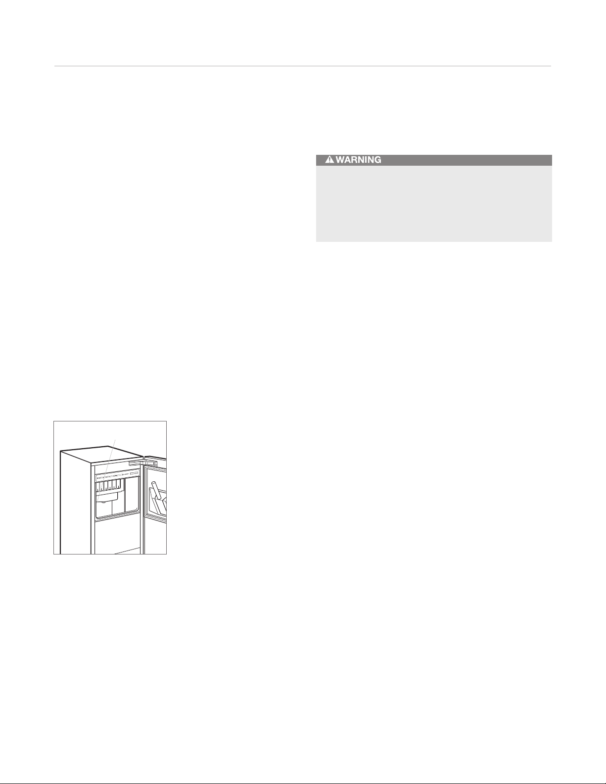
Important product information, including the model and
serial number of your unit are listed on the product rating
plate, located in the upper left corner of the ice bin and on
the back of the unit. Refer to the illustration below.
Proper installation requires connection to the water
supply, a drain and a dedicated electrical circuit. These
connections are the responsibilities of the installer.
Improper connections can result in personal injury,
property damage and improper operation.
RATING PLATE
Location of rating plate.
Page 4
Ice Machine Specications 4
Ice Machine Specications
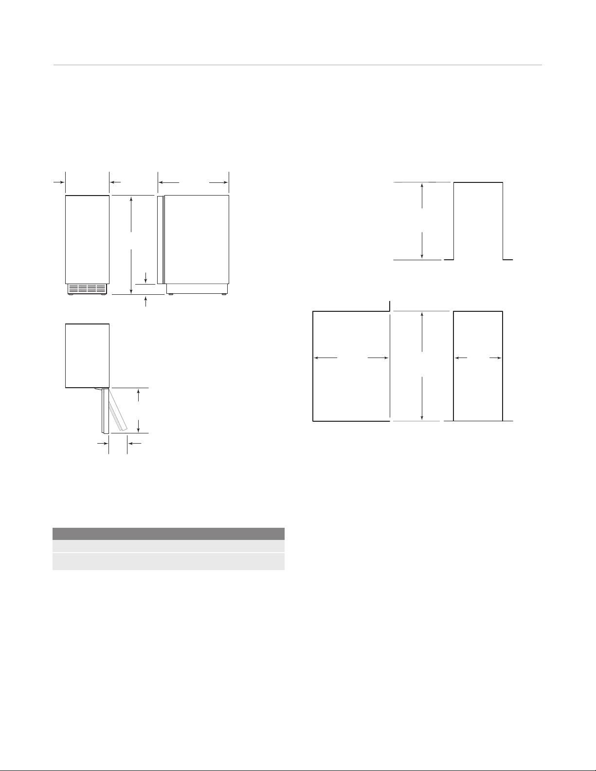
OVERALL DIMENSIONS
143/4" (375) 23" (584)
335/8"
(854)
4" (102)
18"
(457)
6"
(152)
INSTALLATION
24" (610)
OPENING DEPTH
24" (610)
OPENING
DEPTH
341/2" (876)
OPENING
HEIGHT
TOP VIEW
151/4"
(387)
OPENING
WIDTH
FRONT VIEWSIDE VIEW
Overall dimensions do not include panels or handles.
IMPORTANT NOTE:
and water supply be placed in an adjacent cabinet. If they
are placed within the opening, additional cabinet depth
Specications
Ice Storage Capacity 26 lbs (12 kg)
Shipping Weight 117 lbs (53 kg)
may be required.
It is recommended that the electrical
Page 5
Ice Machine Specications 5
E
E
E
subzero.com/specs
Electrical Requirements
The ice machine must be installed with adequate clear‑
ance for electrical connection at the rear of the unit. The
electrical supply for the ice machine requires installation of
a grounded receptacle on a separate circuit, servicing only
this appliance. Follow the National Electrical Code and
local codes and ordinances when installing the receptacle.
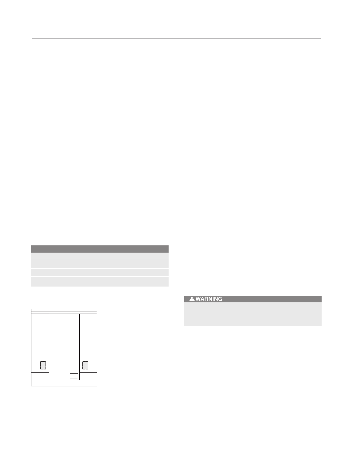
IMPORTANT NOTE: Although it can be located anywhere
on the back wall, it is recommended that the receptacle
be placed in an adjacent cabinet or in the lower right of
the opening. If it is placed within the opening, additional
cabinet depth may be required. Refer to the illustration
below.
Models UC15IO and UC‑15IPO are designed and safe for
use in outdoor applications. When installed outdoors, a
ground fault circuit interrupter (GFCI) is required to reduce
the risk of electrical shock. For outdoor models, or if a
ground fault circuit interrupter (GFCI) is required by local
codes, it must be a breaker type, not an outlet type.
Electrical Requirements
Power Supply 115 V AC, 60 Hz
Receptacle 3‑prong grounding‑type
Circuit Breaker 15 amp
Minimum Circuit 4.1 amp
The electrical supply for the ice machine must be installed
by a qualied electrician in accordance with all applicable
national and local electrical codes. Observe the following:
• The ice machine must be grounded in accordance with
national and local electrical codes.
• A separate fuse or circuit breaker must be provided for
each ice machine.
• The maximum allowable voltage variation is ±10% of
the rated voltage at ice machine start‑up, when the
electrical load is highest.
• The minimum wire size is #14 for less than 100'
or #12 for more than 100'
(31 m) to 200' (61 m), use solid
(31 m)
copper conductor only. The recommended breaker is
15 amp. Local or state electrical code, length of run or
materials used, can increase the minimum wire gauge
required. A qualied electrician must determine the
proper wire size, although #14 is the minimum size
allowed.
• The minimum circuit requirement is used to help select
the wire size of the electrical supply. Minimum circuit
requirement is not the ice machine’s running amp load.
• Observe correct polarity of incoming line voltage.
Incorrect polarity can lead to erratic ice machine oper‑
ation and a safety issue.
Do not use an extension cord or two-prong adapter.
Electrical ground is required on this appliance.
Location of electrical supply.
Page 6

Ice Machine Specications 6
Plumbing Requirements
The ice machine must be installed with adequate clear‑
ance for water and drain connections at the rear of the
unit. Prepare the water supply line and drain connection
before installing the ice machine.
Improper water supply and drain connections can
result in personal injury and property damage.
Plumbing Requirements
Water Supply Line
or PEX tubing
Water Pressure 20–80 psi
Water Temperature 50°F (10°C) – 80°F (27°C)
Water Outlet (gravity drain)
Water Outlet (drain pump)
1
/4" OD copper, braided stainless steel
(1.4–5.5 bar)
3
/4" (19) ID hose
3
/8" (10) ID hose
WATER SUPPLY LINE
For all ice machine models, locate the water supply line as
shown in the illustration below.
IMPORTANT NOTE: It is recommended that the water
supply be placed in an adjacent cabinet within the shaded
area shown in the illustration. If placed within the opening,
additional cabinet depth may be required.
The water supply line should be connected to the house
supply with an easily accessible shut‑off valve between
the water supply and the ice machine. A reverse osmosis
system can be used, provided there is constant water
pressure of 20 psi
(1.4 bar) to 80 psi (5.5 bar) supplied to the
unit at all times. A copper line is not recommended for this
application.
• A cold water supply line must be supplied to the
ice machine. Use
1
/4" (6) OD copper, braided stain‑
less steel or PEX tubing and compression tting (not
included). The incoming water temperature must
remain between 50°F
(10°C) and 80°F (27°C).
• Do not connect the ice machine to a hot water supply.
Be sure all hot water restrictors installed for other
equipment are working, such as check valves on sink
faucets, dishwashers, etc.
• If water pressure exceeds the maximum recommended,
install a water pressure regulator.
• Insulate the water supply line to prevent condensation.
12"
(305)
3"(76)
3"(76)
12"
(305)
1
/2"
(13)
LOCATION OF
WATER LINE
TOP VIEW
Location of water supply line.
8"
(203)
Page 7

Ice Machine Specications 7
subzero.com/specs
Plumbing Requirements
DRAIN CONNECTION
Models UC‑15I and UC‑15IO are gravity drain models that
require a drain tube that is pitched down from the outlet
at the back of the unit to the sanitary sewer connection.
Models UC‑15IP and UC‑15IPO have a built in drain pump
that will pump water up to a drain point, such as a sink.
Gravity drain models are supplied with a drain hose for
gravity draining. A pump model must be used if a gravity
drain is not possible. Both drain methods require routing
to an open site drain. Do not connect directly to a drain
line as bacteria from the drain line may contaminate the
ice machine. Locate the drain in an adjacent cabinet.
Refer to the illustrations below. For installations that will
not allow the drain to be placed in an adjacent cabinet, the
drain must be located within
1
/2" (13) of the back wall.
Improper drainage can lead to water owing back into
ice machine and poor performance.
AIR GAP
DRAIN TUBE
SHUT-OFF
VALVE
WATER
SUPPLY
DRAIN
TUBE
SHUT-OFF
VALVE
WATER
SUPPLY
• The ice machine drain connection is approximately
5"
(127) from the oor.
• For the gravity drain, all horizontal runs of drain lines
must have a
• Drain pump models have a maximum rise of 12'
and a maximum run of 100'
1
/4" (6) per 12" (305) fall.
(31 m).
(4 m)
• Drain pump models will likely require an air gap
between the unit and the drain receptacle.
• The oor drain must be large enough to accommodate
drainage from all drain lines.
• The drain pump discharge line must terminate at an
open site drain.
• If there is not adequate room behind the ice machine
for the drain or waste water receptacle, the drain can
be located below the oor.
WATER FILTER
The water lter provided with the ice machine is designed
to inhibit scale formation, lter sediment, and remove
chlorine odor and taste. The life expectancy of the water
lter is approximately six months during normal usage.
The ice machine control board will monitor water usage
and indicate when replacement is required.
Replacement water lters are avail able through your
authorized Sub‑Zero dealer. For local dealer information,
visit the nd a showroom section of our website, subzero.
com.
Gravity drain models.
Drain pump models.
Page 8

Ice Machine Installation 8
Installation Requirements
• Installation must allow removal of the ice machine for
cleaning and service. Service diagnostics are per‑
formed from the top of the ice machine.
• If the ice machine is installed in a corner, the door
swing may be limited due to handle contact with the
adjacent wall or cabinet. A 90° door stop is provided.
• Do not install the ice machine within 18"
container, compactor or recycling container.
• Do not install the ice machine near heat‑generating
equipment.
• The installation location must not obstruct airow
through the kickplate.
• The installation location must be free of airborne and
other contaminants.
• The ambient air temperature must be between 50°F
(10°C) and 100°F (38°C) for indoor models and between
50°F
(10°C) and 110°F (43°C) for outdoor models.
IMPORTANT NOTE: Failure to follow installation require‑
ments of the ice machine may affect warranty coverage.
(457) of a trash
Installation
Before moving the ice machine into position, make sure
all opening dimensions, electrical and plumbing require‑
ments are complete and accurate. The oor under the ice
machine must be at the same level as the surrounding
nished oor.
Move the ice maker into position near the installation
opening. Remove and discard all packing materials.
Remove the literature packet and drain hose from inside
the ice machine. The bin thermostat clip is shipped with
tape holding it in position. Remove the tape. Also, remove
the tape securing the water shutters.
Although the ice machine has been designed to be
serviced in place, in some cases it may be necessary to
slide the unit out for service or cleaning. The installation
must allow for removal of the unit.
Before moving the ice machine into position, protect
any nished ooring to avoid damage.
The ice machine must be protected if it will be
exposed to ambient temperatures below 32°F
Component failure caused by exposure to freezing
temperatures is not covered by the warranty.
(0°C).
Page 9

Ice Machine Installation 9
subzero.com/specs
Installation
INSTALL THE ICE MACHINE
1) Adjust the leveling legs close to the desired height.
Refer to the illustration below.
2) Reverse the door swing if needed. Refer to steps
outlined on the following pages.
3) Gravity drain models: Install the drain hose (provided)
onto the drain tting on the back of unit and route to
the open site drain. Refer to the illustration below and
plumbing requirements on pages 6–7.
Pump models: Route drain tubing through the drain
tting on the back of the unit and install the drain hose
(provided) on the drain pump. Route the other end of
the drain tubing to the drain site. Refer to the illustra‑
tion below and plumbing requirements on pages 6–7.
4) Use a compression tting to connect the water inlet on
back of ice machine to the prepared
1
/4" (6) OD cold
water line. Refer to the illustration below.
5) Open the shut‑off valve on the water line. Check all
plumbing connections for leaks. Failure to do so could
result in ooding.
6) Plug the power cord into the grounded receptacle.
7) Level the ice machine to assure that the door closes
and seals properly. Place a level on top of the unit and
turn each leveling leg to raise or lower as needed.
8) Move the ice machine into its nal position.
9) Secure the ice machine by installing two #8 x
1
/2" at
head screws through each hinge. Refer to the illustra‑
tion below.
10) Add 1 tablespoon
(15 ml) of undiluted ice machine
sanitizer to a container that will t under the lifted
water shutters. Refer to the illustration below for
location of the water shuttters.
11) Press the CLEAN key pad. Wait three minutes until
the CLEAN light ashes, then add the prepared sani‑
tizer by lifting the water shutters and pouring directly
into the spray area. The ice machine will automatically
time out a ten‑minute sanitizing cycle, followed by
eight rinse cycles, and stop. The CLEAN light will turn
off to indicate that the sanitizing cycle is complete.
This entire cycle lasts approximately 30 minutes.
12) Add one gallon
(3.8 L) of cold water to a container that
will easily t under the lifted water shutters. Lift the
water shutters and pour the water directly into the
spray area. Watch for proper drainage.
13) Press the POWER button.
14) At initial start‑up, the ice machine will need approxi‑
mately 30 minutes to freeze ice and up to ve minutes
to harvest the ice. Wait for rst cycle of cubes to drop
to ensure proper installation.
Leveling.
LEVELING
LEG
DRAIN FITTING
WATER INLET
Drain connection.
HINGE
SCREWS
Secure ice machine.
WATER
SHUTTERS
Location of water shutters.
Page 10

Ice Machine Installation 10
Reverse Door Swing
The hinged side of the door may be reversed to the other
side if needed.
The ice machine is shipped with the door hinged at the
right. The door and hinges are designed for placing
the hinges on either the right or the left side of the unit.
Moving the hinges to the left in the pre‑drilled holes,
allows the door to pivot from the left side.
IMPORTANT NOTE: The plastic molding which covers the
top area of the door, packaged with the ice machine, is
required for this procedure.
1) To begin, remove the four screws that secure the door
hinges to the ice machine. Refer to the illustration
below. Remove the door. Remove the shim located
between the cabinet and bottom hinge, this shim will
transfer to the left side bottom hinge.
HINGE
SCREWS
2) Remove the hinges from the door by removing the four
screws (two per hinge) that secure the hinges to the
door. Refer to the illustration below.
3) Remove the right‑hand upper trim (shaded area) from
the door by removing the two screws that secure it to
the door. Refer to the illustration below. Replace it with
the left‑hand upper trim.
4) Transfer the hinges to the left side of the door and
reinstall. The upper hinge will now be in the lower hinge
position and the lower hinge will now be in the upper
hinge position. Refer to the illustration below.
UPPER
TRIM (RH)
HINGE
HINGE
UPPER
TRIM (LH)
Remove door.
HINGE
Remove hinges and trim.
Transfer hinges.
HINGE
Page 11

Ice Machine Installation 11
TRIM PLATE
SCREWS
subzero.com/specs
Reverse Door Swing
5) Remove the ice machine top cover by removing the
two screws along the back of the unit. Refer to the
illustration below.
6) Remove four screws from the front top rail. Refer to the
illustration below.
7) Pivot the top rail end for end to expose the two left‑
hand top hinge screw holes and reinstall.
TOP COVER
SCREWS
Remove top cover.
Remove front top rail.
TOP RAIL
SCREWS
8) Remove two screws from the lower edge of the bottom
trim plate and slide the trim plate to the right, to cover
the right‑hinge mounting screw holes. The left‑hinge
mounting screw holes will now be exposed. Refer to
the illustration below.
9) Reinstall the door by mounting hinges using the left‑
hinge mounting holes. Reinstall the shim removed in
step 1, between the cabinet and bottom hinge. Check
operation of the door by opening it.
Bottom trim plate.
Page 12

Ice Machine Installation 12
Panel Installation
DOOR PANEL INSTALLATION
You should be sure of the door panel size and placement
before proceeding with the installation. Refer to the chart
for panel specications. If you have questions, contact
your authorized Sub‑Zero dealer or cabinet supplier.
For door handle hardware, a D‑style pull, centered on
the edge opposite the door hinge side is recommended.
Screw heads may need to be countersunk to ensure that
the hardware does not interfere with the panel tting ush
with the door.
Remove the handle side bracket attached to the front of
the door and set aside. Place the door panel lying face
down on a protected surface to ensure that the front will
not be scratched or damaged.
On the back of the panel, position the plastic template
(provided) ush with the top and side edges. Be sure you
are following the exact position for right‑hand or left‑hand
door swing. Refer to the illustration below.
Door Panel Specications
Panel Width 15" (381)
Panel Height 303/8" (772)
Minimum Thickness
Maximum Weight 15 lbs (7 kg)
Dimensions based on 1/8" (3) reveal.
5
/8" (16)
Panel dimensions in the chart are the minimum necessary
to cover the door. The exact dimensions of your door
panel may vary depending on your particular installation.
Once you have located the proper position for the
hardware, mark the holes, remove template, and drill
pilot holes for mounting the hardware. It is best to start
the rst few holes, position the hardware and then drill the
remaining pilot holes. Secure the mounting brackets with
1
#8 x
/2" screws. Refer to the illustrations below.
Install the door panel by engaging the tabbed bracket to
the door rst and then sliding the hinge side hardware
over the positioning screws. You will have a
1
/4" (6) adjust‑
ment, up and down, and side to side.
Template position.
Once you have the door in place, attach the remaining
1
#8 x
/2" screws to the hinge side mounting bracket and
install the hinge covers. Refer to page 14.
Right-hand door panel.
Left-hand door panel.
Page 13

Ice Machine Installation 13
subzero.com/specs
Panel Installation
Exercise caution when drilling holes for mounting
hardware. This is especially critical with inset panels.
If the reveal on the hinge side of the door panel is less
1
than
/4", and the panel has a square corner, severe
nger pinching or damage to the unit may occur.
SIDE PANEL INSTALLATION
With the ice machine, you must securely fasten side
panels to adjacent cabinets and oor. Brackets and
screws are provided for mounting the unit to adjoining
cabinets and side panels.
Side panels should be fastened to the oor and walls
using L‑shaped brackets (not included). To help move the
unit into place, rout out an area in the oor so the bracket
will sit ush with the oor.
Installation
INSTALL KICKPLATE
Once the ice machine is in position, install the kick‑
plate using the screws provided. The kickplate must be
removed for servicing. The oor cannot interfere with
removal. Do not cover the vents of the kickplate to allow
proper airow. The door panel may hang in front of the
vents, but a decorative kickplate must not cover the vents.
If you choose, the kickplate may be painted another color.
Follow these steps: Rough up the surface to be painted
with ne grit sandpaper. Wipe with alcohol to ensure that
the surface is clean and dry. Use an appliance or industrial
grade, oil base, high gloss enamel paint.
Page 14

Ice Machine Installation 14
Installation
90° DOOR STOP
Door stop pins provided with the ice machine will limit the
door swing to 90°. Follow these steps to install:
1) Open the door to approximately 80°.
2) Insert the stop pin into the bottom door hinge (pin
enters from the top). Refer to the illustration below. The
pin must be inserted until the head has made contact
with the hinge body.
3) Insert the stop pin into the top door hinge (pin enters
from the bottom).
4) Check for proper operation.
HINGE COVER INSTALLATION
Install the hinge covers after installation of the ice machine
is complete. The 90° door stop must be installed prior to
installing the hinge covers. It will be necessary to remove
the knock‑out in the hinge cover when the 90° door stop
is used.
Make sure hinges are free of dirt or grease before applying
covers. To install, remove backing paper from the
adhesive pads and bond to the hinge. Attach the magnetic
center covers. Refer to the illustration below.
Installation Checklist
To ensure a safe and proper installation, the following
checklist should be completed by the installer to ensure
that no part of the installation has been overlooked.
INSTALLATION CHECKLIST
Have all electrical and water connections been made?
Is the power cord plugged into a properly grounded
3‑prong outlet, which has been installed in accordance
with all applicable electrical codes?
Is the water supply turned on? Have water supply and
drain connections been examined for leaks?
Is the ice machine drain line routed to an open site
drain for gravity drains and according to instructions
for drain pump models?
Has all packing materials and tape been removed?
Is the ice machine level? Are all leveling legs making
contact with the oor?
Has the kickplate been installed properly? Is there
proper clearance in front of the kickplate for airow?
If applicable, is the door panel installed properly?
If applicable, has the 90° door stop been installed?
Have hinge covers been installed?
DOOR STOP PIN
90° door stop.
KNOCK-OUT
Hinge cover installation.
Has the ice machine and bin been sanitized?
Does the customer understand the unit's operation
and maintenance? Have you given the customer the
warranty package?
Have any installation or service problems been noted
on the product registration card? Has the registration
card been mailed in?
If applicable, has the stainless steel door panel been
inspected for any imperfections? This is to be done
by the dealer or installer with the customer upon com‑
pletion of the installation. Stainless steel panels are
covered by a limited 60‑day parts and labor warranty
for cosmetic defects.
Page 15

Service Information 15
subzero.com/specs
Service Information
If service is necessary, maintain the quality built into your
ice machine by calling Sub‑Zero factory certied service.
For the name and number of Sub‑Zero factory certied
service nearest you, check the contact & support section
of our website, subzero.com or call Sub‑Zero customer
care at 800‑222‑7820.
When calling for service, you will need the model and
serial numbers of your unit. Both numbers are listed on the
product rating plate, located in the upper left corner of the
ice bin and on the back of the unit. Refer to the illustration
below.
If you are storing or disposing of your old refrigerator
or freezer, please do it
safely. Remove the
doors or tightly secure
the doors closed.
Child entrapment
accidents can be tragic.
RATING PLATE
Location of rating plate.
The information and images in this guide are the copyright property of Sub‑Zero, Inc. Neither this guide nor any information or images contained herein may be
copied or used in whole or in part without the express written permission of Sub‑Zero, Inc. ©Sub‑Zero, Inc. all rights reserved.
Wolf, Wolf & Design, Wolf Gourmet, W & Design and the color red as applied to knobs are registered trademarks and service marks of Wolf Appliance, Inc.
Sub‑Zero, Sub‑Zero & Design, Dual Refrigeration, Constant Care and The Living Kitchen are registered trademarks and service marks of Sub‑Zero, Inc.
(collectively, the “Company Marks.”) All other trademarks or registered trademarks are property of their respective owners in the United States and other countries.
Page 16

SUB-ZERO, INC. P. O. BOX 44848 MADISON, WI 53744 SUBZERO.COM 800.222.7820
7024818 REV‑B 10 / 2013
 Loading...