

Sub-Zero & Wolf 30 Gas Range, 36 Gas Range, 48 Gas Range, 60 Gas Range Quick Start Manual

Gas Ranges Installation Guide

GAS RANGES
Contents
3 Safety Precautions
4 Specications
7 Installation
10 Troubleshooting
Features and specications are subject to change at any
time without notice. Visit wolfappliance.com/specs for the
most up-to-date information.
Important Note
To ensure this product is installed and operated as safely
and efciently as possible, take note of the following types
of highlighted information throughout this guide:
IMPORTANT NOTE highlights information that is especially
important.
CAUTION indicates a situation where minor injury or product
damage may occur if instructions are not followed.
WARNING states a hazard that may cause serious injury or
death if precautions are not followed.
IMPORTANT NOTE: Throughout this guide, dimensions in
parentheses are millimeters unless otherwise specied.
IMPORTANT NOTE: Save these instructions for the local
electrical inspector.
2 | Wolf Customer Care 800.222.7820
SAFETY PRECAUTIONS
Product Information
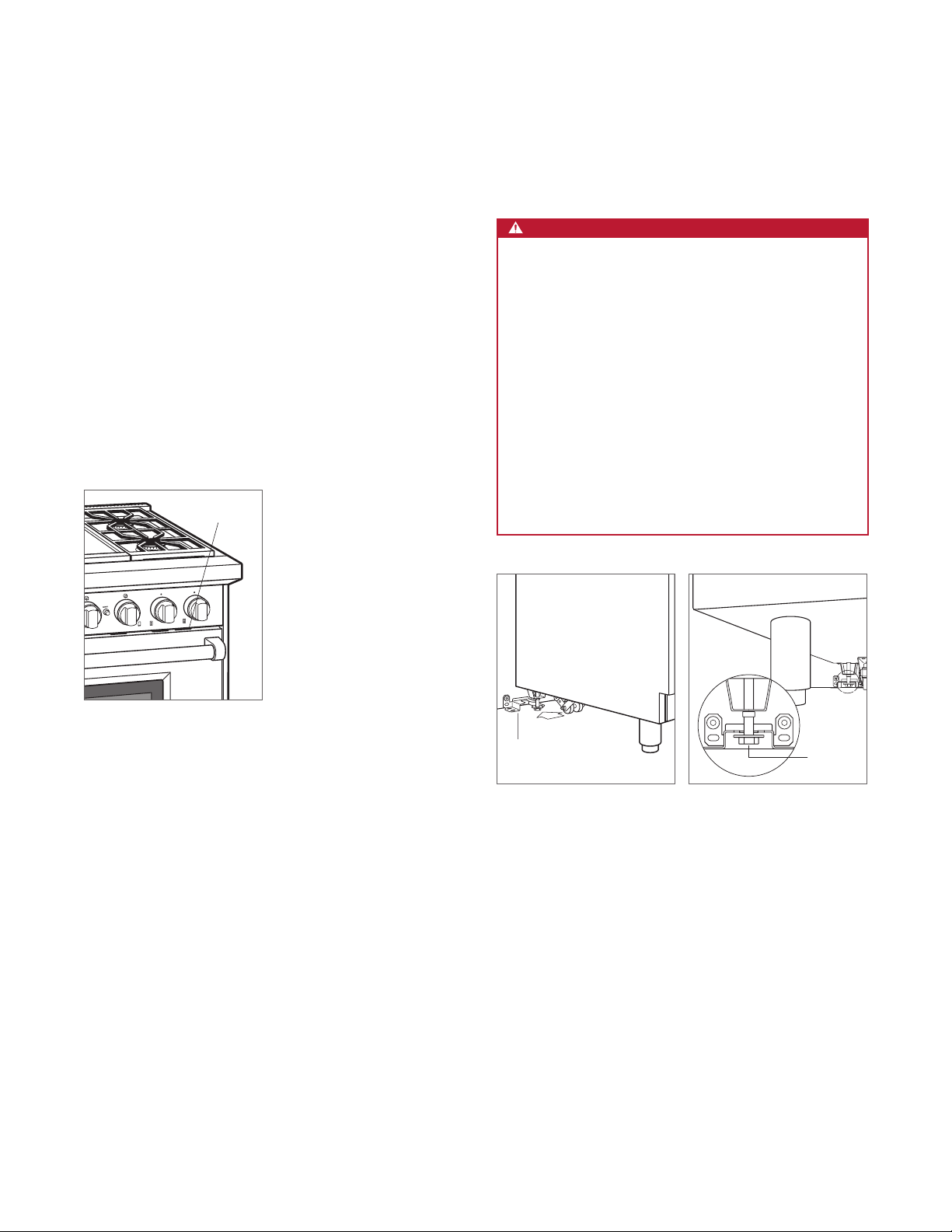
Important product information including the model and
serial number are listed on the product rating plate. The
rating plate is located on the bottom of the control panel
assembly, at the far right, just above the oven door. Refer
to the illustration below.
If service is necessary, contact Wolf factory certied service
with the model and serial number. For the name of the
nearest Wolf factory certied service or for questions
regarding the installation, visit the contact & support section
of our website, wolfappliance.com or call Wolf customer
care at 800-222-7820.
RATING PLATE
IMPORTANT INSTRUCTIONS
WARNING
A child or adult can tip this appliance and be
killed.
Verify the anti-tip device has been properly
installed and engaged. Ensure the anti-tip device
is re-engaged when this appliance is moved. Refer
to the illustrations below for how to verify correct
installation.
To reduce the risk of burns, do not move this
appliance while hot.
Do not operate this appliance without the antitip device in place and engaged. Failure to do so
can result in death or serious burns to children or
adults.
Rating plate location.
ANTI-TIP
DEVICE
Anti-tip device location.
Anti-tip device engaged.
ANTI-TIP
DEVICE
ENGAGED
• This appliance is equipped with casters on two
or more legs and must be installed on 1/8" (3) thick
commercial grade vinyl composition oor nishing
materials or equivalent.
• This appliance is not approved for downward air-
ow ventilation or air curtain equivalent.
• A minimum 20" (508) riser is required when installing
against a combustible surface.
wolfappliance.com | 3

SPECIFICATIONS
Electrical
Installation must be electrically grounded in accordance
with local codes or, in the absence of local codes, with the
National Electrical Code, ANSI/NFPA 70.
Locate the electrical supply ush with the wall or oor and
within the shaded area shown in the illustration on page 6.
A separate circuit, servicing only this appliance is required.
A ground fault circuit interrupter (GFCI) is not recommended
and may cause interruption of operation.
ELECTRICAL REQUIREMENTS
Electrical Supply grounded, 110/120 VAC, 60 Hz
Service 15 amp dedicated circuit
Receptacle 3-prong grounding-type
Power Cord 6'
(1.8 m)
4 | Wolf Customer Care 800.222.7820
SPECIFICATIONS
Gas Supply
Installation must conform with local codes or, in the absence
of local codes, with the National Fuel Gas Code.
Locate the gas supply within the shaded area shown in the
illustration on page 6.
The range is equipped for use with natural or liquid propane
(LP) gas. It is design certied by the Canadian Standards
Association (CSA) for natural or LP gases. The product
rating plate has information on the type of gas that should
be used. For rating plate location, refer to the illustration
below. If this information does not agree with the type of gas
available, check with the local gas supplier.
GAS SUPPLY REQUIREMENTS
NATURAL GAS
Gas Supply Pressure 5" (12.5 mb) WC
Min Line Pressure 7"
Max Pressure to Regulator 14"
LP GAS
Gas Supply Pressure 10" (25 mb) WC
Min Line Pressure 11" (27.4 mb) WC
Max Pressure to Regulator 14"
(34.9 mb) WC, .5 psi (3.5 kPa)
(34.9 mb) WC, .5 psi (3.5 kPa)
(17.5 mb) WC
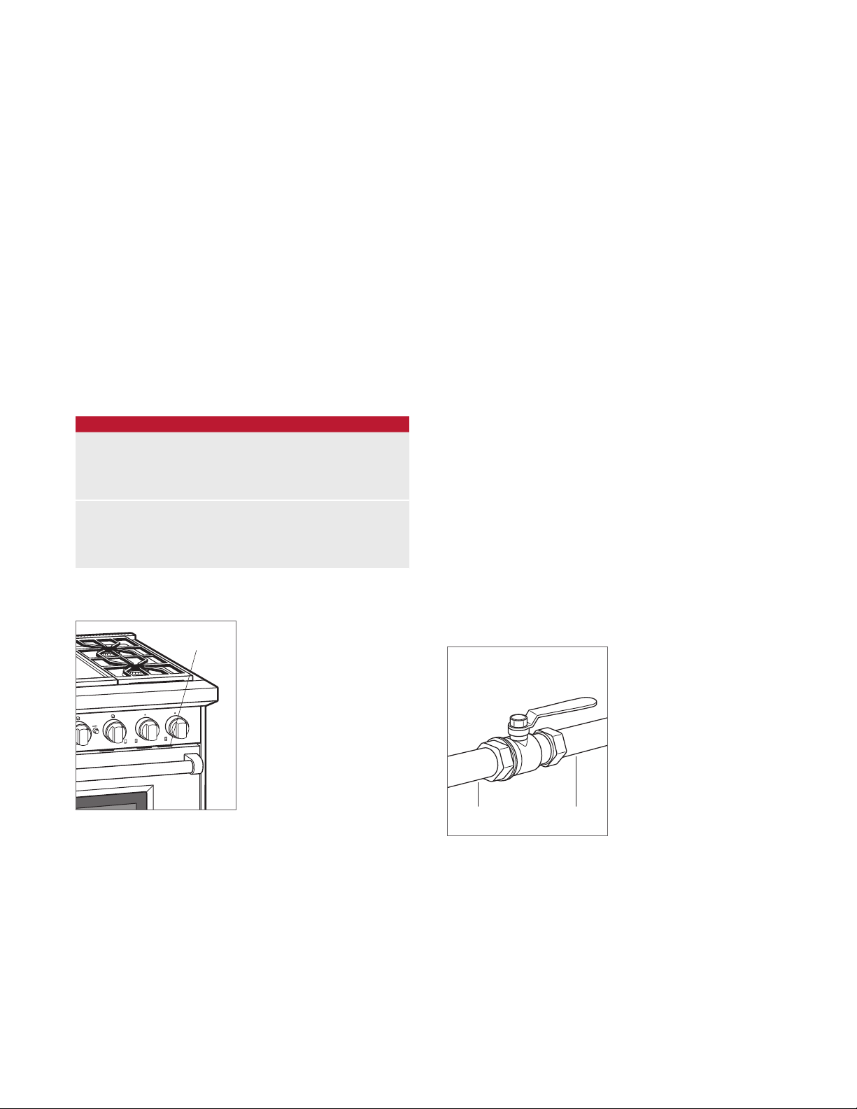
The range must be connected to a regulated gas supply.
The supply line must be equipped with an approved external
gas shut-off valve located near the range in an accessible
location. Do not block access to the shut-off valve. Refer to
the illustration below.
3
A gas supply line of
the range. If local codes permit, a certied, 3'
1
/2" (13) or 3/4" (19) ID exible metal appliance connector is
recommended to connect the units
/4" (19) rigid pipe must be provided to
(.9 m) long,
1
/2" NPT female inlet to
the gas supply line. Pipe joint compounds, suitable for use
with natural or LP gas should be used.
The appliance and its shut-off valve must be disconnected
from the gas supply piping system during any pressure
testing of the system at test pressures in excess of .5 psi
(3.5 kPa)
. The appliance must be isolated from the gas
supply piping system by closing its individual manual shutoff valve during any pressure testing of the system at test
pressures equal to or less than .5 psi
Wolf natural gas ranges will function up to 8,600'
(3.5 kPa).
(2621 m) in
altitude without adjustment. If the installation exceeds this
elevation, contact an authorized Wolf dealer for a high altitude conversion kit. LP models do not require conversion.
RATING PLATE
Rating plate location.
SHUT-OFF VALVE
OPEN POSITION
Gas shut-off valve.
GAS SUPPLYTO APPLIANCE
wolfappliance.com | 5
SPECIFICATIONS
Gas Range
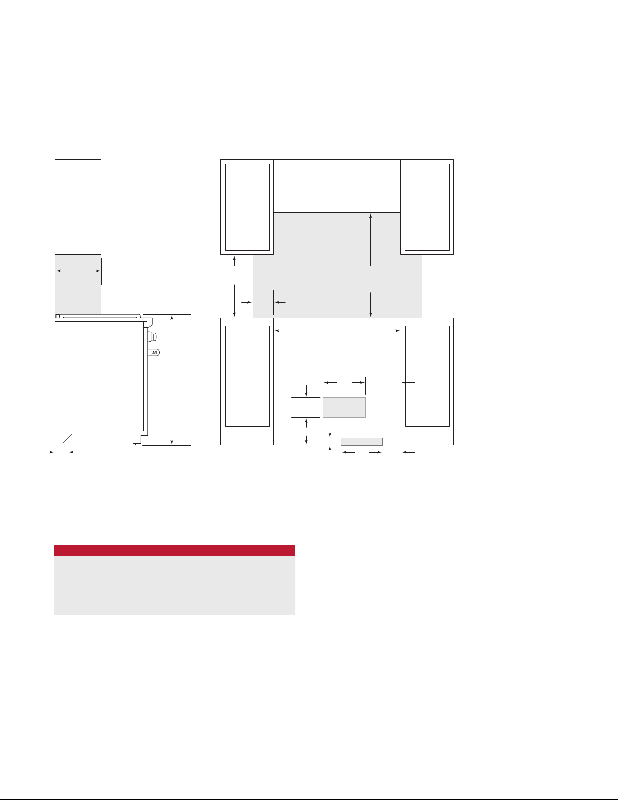
INSTALLATION
13"
(330)
LOCATION OF GAS AND
ELECTRICAL EXTENDS
ON FLOOR
37" (940)
TO COOKING
SURFACE
18"
(457)
6"
(152)
OPENING WIDTH
53/4"
(146)
73/4" (197)
30" (762) TO 36" (914)
TO BOTTOM OF
VENTILATION HOOD
W
12"
(305)
10" (254)
E
2" (51)
*
G
3"
(76)
*Without ventilation hood, 42" (1067) minimum clearance countertop to combustible materials, charbroiler and GR488 require non-combustible materials.
NOTE: Shaded area above countertop indicates minimum clearance to combustible surfaces,
combustible materials cannot be located within this area.
For island installation, 12"
(305) minimum clearance back of range to combustible rear wall above countertop.
FRONT VIEWSIDE VIEW
12"
(305) GAS5"(127)
GAS RANGE
WIDTH W
30" Range 30" (762)
36" Range 36" (914)
48" Range 48" (1219)
60" Range 601/4" (1530)
6 | Wolf Customer Care 800.222.7820

INSTALLATION
SPRING HINGES
SPRING HINGE
Preparation
Before moving the range, protect any nished ooring and
secure oven door(s) closed to prevent damage.
To lighten the load or to t through a door way, the oven
door(s) can be removed. Only remove if necessary. Do not
remove griddle or any other component. Door removal
should only be done by a certied installer or service
technician.
For removal, a hinge pin will be inserted into the appropriate
hinge shown in the illustrations below. The pin(s) are located
inside the oven door. For single oven ranges, the hinge pin
must be inserted in the right hinge. For double oven ranges,
the pins must be placed in the outer two hinges.
CAUTION
Failure to insert the hinge pin in the appropriate hinge
arm will cause damage to the range.
OVEN DOOR REMOVAL
1 Insert the hinge pin into the appropriate hinge.
2 Remove the lower kickplate assembly to access the
lower hinge retainer mounting screws.
3 Open the oven door and remove both upper and lower
hinge retainer mounting screws. The oven gasket may
have to be moved slightly to access the bottom screws.
4 Move the hinge retainer plate forward slightly. The hinge
retainer plate will remain on the door hinge after the
mounting screws have been removed.
5 Carefully close the oven door to approximately 60°, then
lift the door up and out. A slight rocking motion may be
required for removal.
HINGE
RETAINER
PLATE
HINGE
PIN
UPPER
MOUNTING
SCREW
Single oven ranges.
SPRING HINGES
Double oven ranges.
KICKPLATE
Oven door removal.
wolfappliance.com | 7

INSTALLATION
Placement
Do not lift or carry the oven door by the door handle. The
range has rear casters which allow for easy movement by
lifting the front of the unit.
Use an appliance dolly to move the unit near the opening.
Remove and recycle packing materials. Do not discard the
anti-tip bracket supplied with the range.
If a riser has been specied, refer to the installation instructions packaged with the riser. The riser must be installed
before the range is installed.
Leveling
Raise the unit to its desired height by adjusting the front
legs and rear casters. The front legs can be adjusted by
rotating the hex agonal leg clockwise to raise and counterclockwise to lower. The rear casters can be adjusted by
rotating the wheel assembly.
8 | Wolf Customer Care 800.222.7820
INSTALLATION
7/8" (22) MAX
ANTI-TIP
BOLT
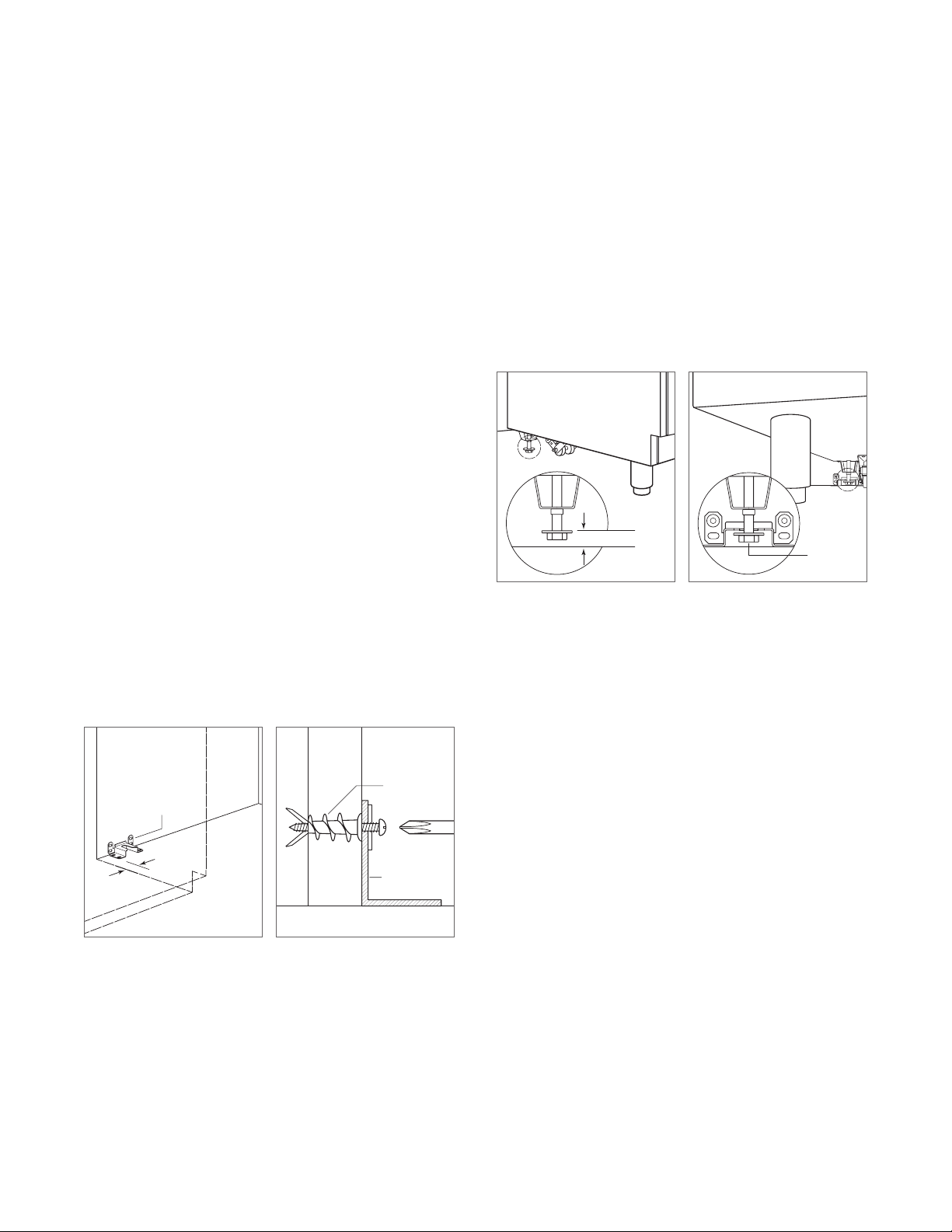
Anti-Tip Bracket
To prevent the unit from tipping forward, the anti-tip bracket
must be installed. To ensure the anti-tip bolt engages the
bracket, position the bracket 3"
(76) from the left side of the
opening. Refer to the illustration below.
INSTALL BRACKET
Drywall application | After properly positioning the anti-tip
bracket, mark holes, then use a Philips screwdriver or a low
rpm power drill to drive the wall anchor into the surface of
the wallboard until ush. Pre-drill holes if needed. For hard
1
wallboard or double-board construction, use a
7
For solid plaster, use a
/16" drill bit. Refer to the illustration
/4" drill bit.
below. Use #8 screws and at washers to fasten the bracket
to the wall.
Wood oor application | After properly positioning the
3
anti-tip bracket, drill
/16" (5) pilot holes through the oor.
Use #12 screws and at washers to secure the bracket to
the oor.
Concrete oor application | After properly positioning
3
the anti-tip bracket drill
1
minimum of 1
/2" (38) deep. Use 3/8" wedge anchors to
/8" (10) holes into the concrete a
secure the bracket to the oor.
ANTI-TIP BOLT ADJUSTMENT
Once the bracket is secure, adjust the anti-tip bolt so the
7
top of the washer is
/8" (22) maximum from the oor. Slide
the range into the opening and verify the anti-tip bolt is
engaged. Refer to the illustrations below.
ANTI-TIP
DEVICE
ENGAGED
Anti-tip bolt adjustment.
Anti-tip bolt engaged.
ANTI-TIP
BRACKET
3" (76)
Anti-tip bracket location.
WALL
ANCHOR
ANTI-TIP
BRACKET
Wall anchor installation.
wolfappliance.com | 9

INSTALLATION
Gas Supply Connection
All connections to the gas piping must be wrench-tightened.
Do not overtighten or allow pipes to turn when tightening.
If a exible metal connector is being used, verify it is not
kinked, then attach the gas supply line to the regulator on
the range. Open the valve and check for leaks by placing a
liquid detergent solution onto all gas connections. Bubbles
around connections indicate a gas leak. If a leak appears,
close the shut-off valve and adjust connections.
Troubleshooting
IMPORTANT NOTE: If the range does not operate properly,
follow these troubleshooting steps:
• Verify electrical power is supplied to the range.
• Verify the gas supply shut-off valve is in the open
position.
• If the range does not operate properly, contact Wolf
factory certied service. Do not attempt to repair the
range. Wolf is not responsible for service required to
correct a faulty installation.
10 | Wolf Customer Care 800.222.7820
 Loading...