

Page 1

subzero.com 800.222.7820
CT Induction Cooktop
Service Manual
General Information 2
Installation Information 5
Controls & Operation 9
Component Access & Removal 14
Troubleshooting Guide 18
Technical Data 20
Wiring Diagrams 21
Page 2
General Information
IInndduuccttiioonn CCooookkttoopp
1-2
INTRODUCTION
This Wolf Induction Cooktop Technical Service Manual, Part #806657, has been compiled to provide the most recent
technical service information about the Wolf Induction Cooktops. This information will enable the service technician
to troubleshoot and diagnose malfunctions, perform necessary repairs and return a Wolf Induction Cooktop to proper
operational condition.
The service technician should read the complete instructions contained in this Service Manual before initiating any
repairs on a Wolf Appliance.
IMPORTANT SAFETY INFORMATION
Below are the Product Safety Labels used in this manual. The "Signal Words" used are WARNING and
CAUTION.
Please note that these safety labels are placed in areas
where awareness of personal safety and product safety
should be taken and lists the precautions to be taken
when the signal word is observed.
TECHNICAL ASSISTANCE
If you should have any questions regarding a Wolf
appliance and/or this manual, please contact:
Wolf Appliance, Inc.
ATTN: Service Department
P.O. Box 44988
Madison, WI 53744-4988
Customer Service
Phone #: (800) 332 - 9513
Technical Assistance
Phone #: (800) 919 - 8324
Parts / Warranty Claims
Phone #: (800) 332 - 9513
Customer Service E-Mail Address
customerservice@wolfappliance.com
Customer Service & Technical Assistance
Facsimile #: (608) 441 - 5887
Parts / Warranty Claims
Facsimile #: (608) 441 - 5886
Office Hours:
7:00 AM to 7:00 PM Central Standard Time
Monday through Friday
This manual is designed to be used by Authorized Service Personnel only. Wolf Appliance, Inc. assumes
no responsibility for any repairs made to Wolf appliances by anyone other than Authorized Service
Technicians.
INDICATES THAT HAZARDOUS OR UNSAFE PRACTICES COULD RESULT IN SEVERE PERSONAL
INJURY OR DEATH
Indicates that hazardous or unsafe practices could
result in minor personal injury or product and/or
property damage
In addition, please pay attention to the signal word
“NOTE”, which highlights especially important information within each section.
The information and images are the copyright property of Wolf Appliance, Inc., an affiliate of Sub-Zero, Inc. Neither
this manual nor any information or images contained herein may be copied or used in whole or in part without the
express written permission of Wolf Appliance, Inc., an affiliate of Sub-Zero, Inc. © Wolf Appliance, Inc., all rights
reserved.
Page 3
General Information
IInndduuccttiioonn CCooookkttoopp
1-4
WARRANTY INFORMATION
This page contains a summary of the 2 & 5 Year Warranty that is supplied with every Wolf product, followed by
details and notes about the warranties.
TWO & FIVE YEAR Warranty Summary
• Two year TOTAL PRODUCT warranty, *parts and labor.
• Limited Parts Only Warranty for the 3rd through 5th year on the following parts only:
Electric heating elements
Electronic Control Boards
Warranty Details:
The warranty applies only to products installed for normal residential use. The warranty applies only to product
installed in the United States or Canada.
Warranty Notes:
• All warranties begin at the time of the unit’s initial installation.
• All Warranty and Service information collected by Wolf Appliance, Inc., is arranged and
stored under the unit serial number and/or the customer’s name. Please note that Wolf Appliance, Inc.,
requests that you have the model serial number available whenever contacting the
factory or parts distributor.
• See Figure 1-1 for serial tag layout.
• See Figure 1-2 for serial tag location.
Wolf Appliance Company, Inc.
VOLTS :
Hz :
MODEL# : XXXXXX-X
INDUCTION COOKTOP
FOR HOUSEHOLD USE ONLY
120/208
60
"DO NOT IMMERSE IN WATER" "NE PAS PLONGE DANS L'EAU"
FITCHBURG, WI
SERIAL# : XXXXXXXX
KW :
-2
120/240
X.X
X.X
3 WIRE
Page 4

General Information
IInndduuccttiioonn CCooookkttoopp
1-5
MODEL NUMBER KEY
Refer to this key for an example of the model numbers.
Model: CT 15 I / S
Product Type
Size
Fuel
Feature (If Applicable)
Finish
Product T
ype
CT Cooktop
IM Integrated Gas
Multifunction Cooktop
IG Integrated Grill Cooktop
IS Integrated Steamer Cooktop
IF Integrated Fryer Cooktop
Size
15 15 - inch wide unit
30 30 - inch wide unit
36 36 - inch wide unit
Fuel
E Electric
I Induction
G Natural Gas
LP Propane Gas (Propane Gas will be indicated by -LP at the end of the model number. Example: CT36G/S-LP)
Finish
S Classic Stainless Steel
P Platinum Stainless Steel (Not Available for IM, IG, IS and IF)
B Carbon Stainless Steel (Not available for gas models. Not available for IM, IG, IS and IF)
Page 5

General Information
IInndduuccttiioonn CCooookkttoopp
1-6
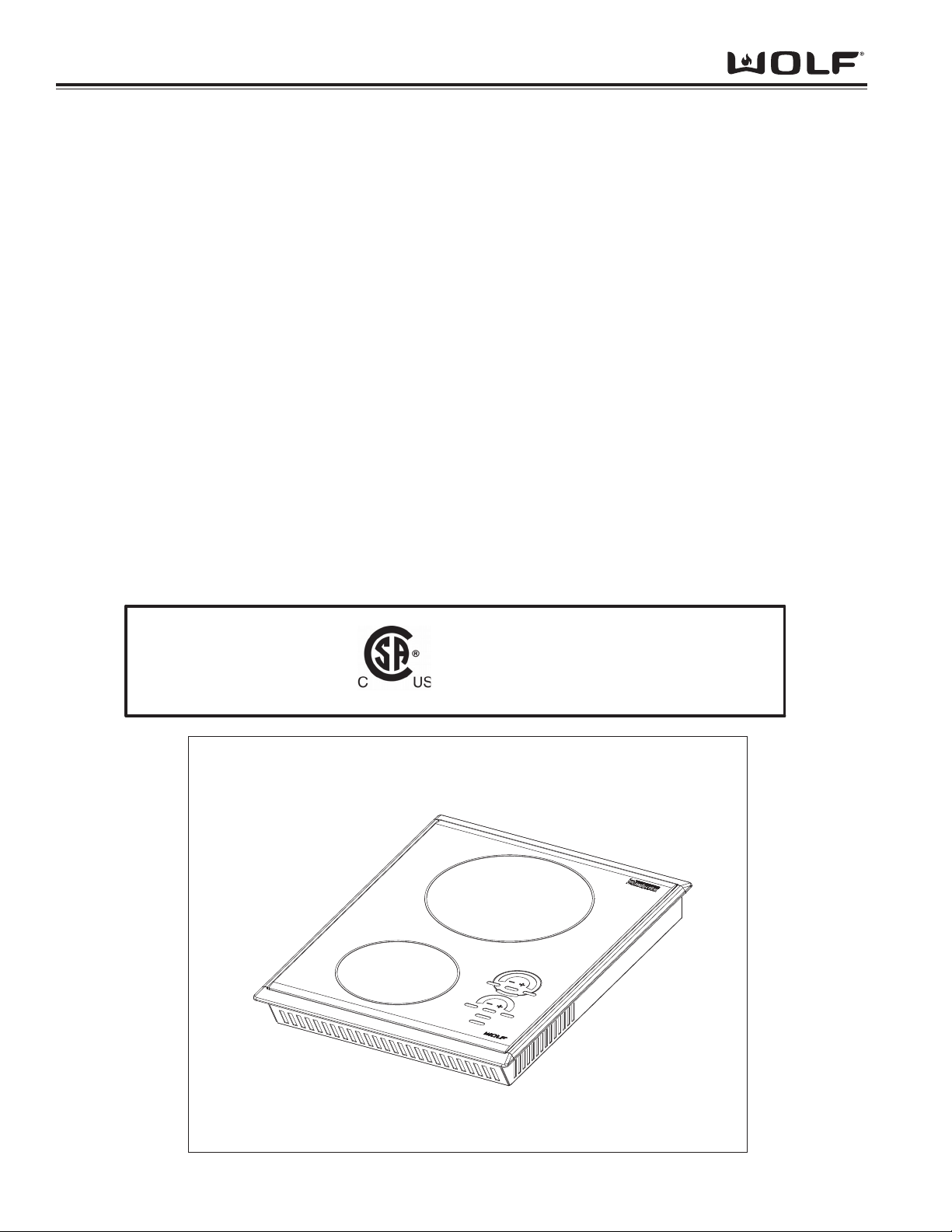
MODEL CONFIGURATIONS
Model Numbers Descriptions
CT15I/S Cooktop 15” Induction, Stainless Steel Trim
15” Electric
MODEL FEATURES
• Illuminated control lighting.
• Graduated control lighting.
• Lock key and universal off.
• True simmer setting on all elements.
• Melt setting on all elements.
• Hot surface indicators on all elements.
• Finish available in classic stainless steel.
• Temperature limiter to ensure that safe operating temperature of glass ceramic is never exceeded.
Page 6

IInndduuccttiioonn CCooookkttoopp
Installation Information
2-2
INDUCTION COOKTOP
INSTALLATION INFORMATION
This section of the manual covers some of the installation issues a service technician may need to know when servicing a Wolf Induction Cooktop. If additional information is needed after reviewing this section of the manual, please
refer to the Installation Guide or contact the Wolf Appliance Customer Service Department.
Electrical Requirements - Induction
Nominal Voltage
CT15I – 240V/15amp /60Hz - (20 Amp Service)
NOTE:208VACinstallation is not recommended.
Maximum Connected Load
CT15I – 3.6Kw (240V)
The Wolf Induction Cooktops require a separate, grounded three-wire service with their own circuit breaker. These
appliances must be installed in accordance with National Electrical Codes, as well as all state, municipal and local
codes. The correct voltage, frequency and amperage must be supplied to the appliance from a dedicated, grounded
circuit which is protected by a properly sized circuit breaker or time delay fuse. The proper voltage, frequency and
amperage ratings are listed on the product rating plate. The cooktops are provided with a 48" (1219 mm) conduit
consisting of two insulated hot lead conductors (copper) and one insulated ground conductor (copper).
THIS APPLIANCE MUST BE PROPERLYGROUNDED AT ALLTIMES WHEN ELECTRICALPOWER IS APPLIED.
DO NOT GROUND THE APPLIANCE WITH THE NEUTRAL(WHITE) HOUSE SUPPLYWIRE. ASEPARATE
GROUND WIRE MUST BE UTILIZED.
IF ALUMINUM HOUSE SUPPLYWIRING IS UTILIZED, SPLICE THE APPLIANCE COPPER WIRE TO THE ALUMINUM HOUSE WIRING USING SPECIALCONNECTORS DESIGNED AND CERTIFIED FOR JOINING COPPER
AND ALUMINUM. FOLLOW THE CONNECTOR MANUFACTURES RECOMMENDED PROCEDURE CAREFULLY. IMPROPER CONNECTION CAN RESULT IN AFIRE HAZARD.
TO ELIMINATE THE RISK OF BURNS OR FIRE BYREACHING OVER HEATED SURFACE UNITS, CABINET
STORAGE SPACE LOCATED ABOVE THE SURFACE UNITS SHOULD BE AVOIDED. IF CABINET STORAGE IS
TO BE PROVIDED, THE RISK CAN BE REDUCED BYINSTALLING ARANGE HOOD THAT PROTECTS HORIZONTALLYAMINIMUM OF 5" (127 MM) BEYOND THE BOTTOM OF THE CABINETS.
Page 7
IInndduuccttiioonn CCooookkttoopp
Installation Information
2-3
INDUCTION COOKTOP
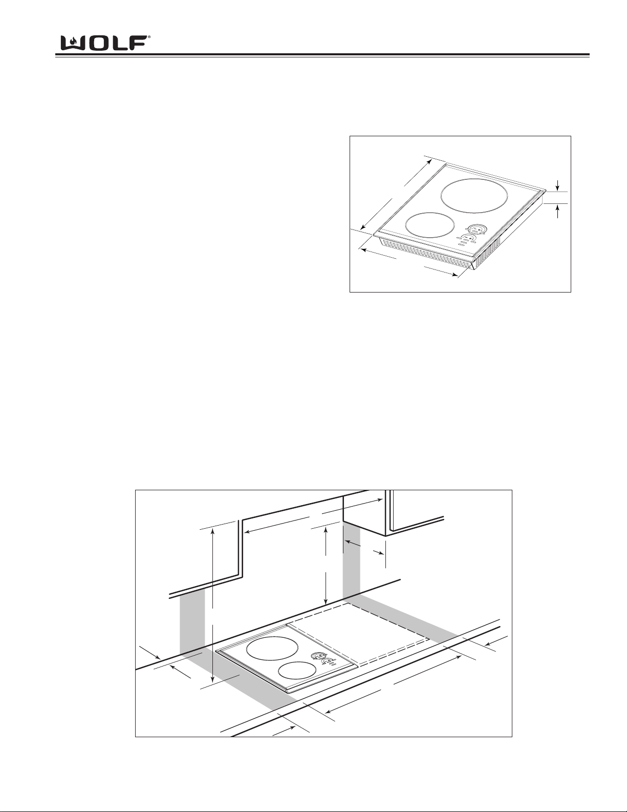
PRE-INSTALLATION SPECIFICATIONS
Countertop Location
Dimension Description
A Minimum flat countertop surface. Must be equal to
or greater than cooktop width.
B Minimum 2-inches (152mm) wide clearance from
the cooktop side edge to any combustible surface
up to 18 inches (457mm) above the cooktop
(noted by shaded area).
C Minimum 2-inches (152mm) wide clearance from
the cooktop side edge to any combustible surface
up to 18 inches (457mm) above the cooktop
(noted by shaded area).
Overhead Cabinet Dimensions
Dimension Description
D Minimum spacing between cabinets directly over cooktop, must be greater than or equal to the nomi-
nal width of the cooktop unit.
E Minimum 18 inches (457mm) vertical distance from the countertop surface to the bottom of cabinets
adjacent to the cabinet directly above the cooktop unit.
F Minimum 24-inches (610mm) clearance between the top of the cooking surface and the bottom of
wood or metal cabinet which is protected by not less than 1/4-inch (6mm) flame retardant millboard
covered with not less than No. 28 MSG sheet steel, 0.015-inch (.4mm) stainless steel or 0.024-inch
(.5mm) copper. Minimum 30” (762mm) clearance between the top of the cooking surface and the bottom of an unprotected wood or metal cabinet.
G Minimum 1-1/2-inches (38mm) from rear wall.
H Maximum 13-inch (330mm) depth of overhead cabinets.
Figure 2-2. Pre-Installation Specifications
Figure 2-1. Overall Dimensions
NOTE:Dimension may vary by ± 1/8” (3mm).
21”
(533mm)
15”
(381mm)
3 1/4”
(83mm)
D
H
E
F
G
C
A
B
Page 8

INDUCTION COOKTOP
Countertop Cut-out Dimensions
This cooktop is designed to fit a standard 24" (610 mm) deep base
cabinet with a 25" (635 mm) deep countertop. Before making the
countertop cut-out, verify that the cooktop will clear the side walls of
the base cabinet below. There should be at least 5-1/2" (140 mm) to
7" (178 mm) clearance between the top countertop surface and any
combustible surface directly below the unit. This includes upper
edges of drawers located directly below unit. Refer to the following
illustrations for cut-out dimensions.
NOTE:Locate the junction box within reach of the 48" (1219 mm)
conduit, and so as to be accessible when the cooktop unit is
installed.
NOTE:Plastic or other utensils with low melting temperatures should
not be located in drawers directly below unit.
IInndduuccttiioonn CCooookkttoopp
Installation Information
2-4
Figure 2-4. Cut-out Dimensions
Figure 2-3. Overhead View of Countertop
NOTE:Dimension may vary by ± 1/8” (3mm).
NOTE: Dimensions in
parentheses are in millimeters.
(356)
14"
CUT-OUT
WIDTH
(489)
191/4"
CUT-OUT
21/2"min
(64)
FRONT OF COUNTERTO
NOTE: Dimensions in parentheses are in millimeters.
DEPTH
P
30"
(762)
13"
(330)
191/4" (489)
COOKTOP CUT-OUT
DEPTH
21/2"min
(64)
24" OR 30"*
(610 or 762)
TO COOKING
SURFACE
18"
(457)
3"
(76)
14" (356)
CUT-OUT
33" (838)
RECOMMENDED
CABINET WIDTH
WIDTH
61/4"
(159)
36"(914)
STANDARD
FLOOR TO
COUNTER
HEIGHT
E
15"
(381)
15"
(381)
RIGHT SIDE
CABINET VIEW
NOTE: Application shown allows for installation of two 15" (381 mm) modules side-by-side.
* Minimum 24" (610 mm) from protected cabinet or 30" (762 mm) from unprotected cabinet to cooking surface.
18"
(457)
3"
(76)
Page 9

INDUCTION COOKTOP
INSTALLATION PROCEDURE
Install
• Insert cooktop into countertop opening and center cooktop. Check that the front edge of the cooktop is
parallel to the front edge of the countertop. Check that all
required clearances are met.
• To attach hold down brackets to the sides of the unit, insert
holddown clip into the rectangular punch-out in the pan and
push down.
• Install the clamping screws into the bracket and tighten until
screw contacts the underside of the countertop.
(See Figure 2-5).
NOTE: Do not over tighten screws.
NOTE: Do not use caulk or silicon to secure the unit to the countertop.
Installation of Multiple Cooktops
If this cooktop is to be used with any combination of additional cooktop units or modules with a filler strip, the cut-out
width is calculated by adding the corresponding units' cut-out dimensions plus 1-1/4" (32 mm) for each additional
unit. (See Figure 2-6).
IInndduuccttiioonn CCooookkttoopp
Installation Information
2-5
Figure 2-5. Attaching Hold Down Clamp
Figure 2-6. Multiple Cooktop Installation
COOKTOP
COUNTERTOP
BRACKET
CLIP
31/2" (89 mm)
CLAMPING
SCREW
593/4" (1518) FOUR MODULES CUT-OUT WIDTH
(See Design Guide)
441/2" (1130) THREE MODULES WIDTH
(See Design Guide)
291/4" (743)
TWO MODULES WIDTH
21/2"min
(64)
14"
(356)
CUT-OUT
WIDTH
191/4"
(489)
CUT-OUT
DEPTH
FRONT OF COUNTERTOP
NOTE: Dimensions in parentheses are in millimeters.
Page 10

IInndduuccttiioonn CCooookkttoopp
Operation Information
3-2
IF A CRACK APPEARS IN THE GLASS SURFACE, DISCONNECT THE APPLIANCE IMMEDIATELY TO AVOID
ANY RISK OF ELECTRICAL SHOCK.
NEVER USE COOKING SURFACE AS A STORAGE SPACE OR CUTTING BOARD.
NEVER ALLOW POWER CABLES FOR OTHER ELECTRICAL APPLIANCES TO TRAIL ACROSS THE COOKING SURFACE.
DO NOT LEAVE EMPTY PANS ON THE COOKING SURFACE IN CASE OF RESIDUAL HEAT OR IF THE UNIT
IS TURNED ON BY MISTAKE.
PRINCIPLES OF INDUCTION
Introduction
There are two techniques of glass-ceramic heating:
• Infrared.
• Induction.
The difference is only obvious once the cooking zones are
turned on. The Infrared one glows red while the the induction doesn’t seem to operate.
The Infrared is provided with radiant or halogen sources
that transmit heat by radiation or conduction. Induction
Cooktops produce a magnetic field which passes through
the glass ceramic to the pan. When ferro magnetic cookware is used, this magnetic field excites the molecules in
the pan, causing them to vibrate at a very high frequencies,
producing heat.
The principles of heating by induction is a natural phenomenon discovered in the 19th century by several physicists,
among whom a certain Leön Foucault. He highlighted the development of currents facing the magnetic field in a
moving metallic mass or a fixed metallic mass run though by a variable magnetic flux. These eddy currents comparable to short-circuits cause a heating effect (Joule effect) in the mass.
The operating principle is innovating. Contrary to other cooking modes, it is the container itself, which heats and not
the cooking surface. This results in a very responsive method of cooking.
You put a saucepan on the cooking zone that is sufficient to initiate the heat while the cooking surface remains cool.
the heating element is nothing but the container metal, which transforms the magnetic energy into thermal energy.
Induction qualities are flexibility, low inertia, easy cleaning, good efficiency and thermal safety. Induction efficiency
may reach up to 90% according to the types of cooking. With such a technique, the container only heats. Inertia is
therefore low, and above all, the plate stepping from the mildest temperature to the strongest power, in an instant
and while diffusing heating a homogeneous way, attracts more and more consumers.
Induced currents
Electronic circuit
Induction coil
Figure 3.1. Principles of Induction
Induced currents
Induction coil
Electronic circuit
+
-
Page 11

IInndduuccttiioonn CCooookkttoopp
Operation Information
3-3
PRINCIPLES OF INDUCTION
Operational Principles
An induction cooktop operates thanks to the electromagnetic properties of most containers used on the traditional
cooktop.
At a first approximation, you can compare this cooktop with a transformer of which the secondary winding would
have been shorted. A significant internal current arises therein and causes quick heating.
The saucepan can be compared with a shorted set of concentric whose internal resistance is not
zero.
From the function keys, you can control the electrical power supply to the transformer primary
winding that generates a magnetic field. This field induces currents at the bottom of the container placed on the cooking zone. These induced currents heat immediately the container, which
transmits the produced heat to the food contained inside. Cooking is performed practically without any loss of energy. The appliance heating power is pushed to its maximum.
Figure 3.2. Operation Principles
TRANSFORMER
INDUCTION UNIT
Magnetic Conductor 1 Saucepan
Secondary Winding 2 Saucepan
Gap 3 Glass-Ceramic Plate
Primary Winding 4 Inductor (Element)
Magnetic Conductor 5 Ferrite
Magnetic Field 6 Magnetic Field
1
2
3
4
5
6
Page 12

IInndduuccttiioonn CCooookkttoopp
Operation Information
3-4
INDUCTION COOKTOP OPERATION
Control Operation
The Wolf Induction cooktop operates by automatically cycling the heating elements between zero power and full
power. As the heat is increased on the control panel, the element will stay on at full power for longer periods and
the element will have shorter periods of zero power.
Residual Heat Indicators
As an added safety precaution, residual heat indicator lights will illuminate when the surface temperature of the
glass is above 150°F. Each heating element has an independently controlled light located to the right of that element. Even if the cooktop controls are turned off, the indicator light(s) will illuminate to show the user that the cooktop surface remains hot.
Modes of Operation
Lock Mode: All keypad operation on the control panel is disabled and all of the heating elements are
de-energized. A steady glowing light within the "key" symbol indicates the unit is locked.
• To unlock the control, touch and hold the "key" symbol for 3 seconds. The unit will beep twice and the light
with-in the "key" symbol will go out. The control unit is now in the idle mode. (See Figure 3-4).
• To lock the control, touch and hold the "key" symbol for three seconds. The unit will beep three times
and the light within the "key" symbol will illuminate. (See Figure 3-4).
NOTE: When the unit is powered up for the first time or if there was a power outage, the unit will default to this
mode.
Idle Mode: After unlocking the control panel as described in Lock Mode, the unit enters the idle mode of operation.
The only valid keypad operations are the "OFF /ON" for each element and the "key" symbol.
Figure 3-3. Control Panel Figure 3-4. Lock Key
-
OFF/ON
H
I
-
+
HIGH
R
P
E
O
W
+
MELT
-
OFF/ON
H
I
-
+
HIGH
R
P
E
O
W
MELT
+
MELT
OFF/ON
OFF
HIGH
MELT
OFF/ON
OFF
HIGH
Page 13

IInndduuccttiioonn CCooookkttoopp
Operation Information
3-5
Front Element Operation
To activate a heating element, you must first touch the corresponding "OFF/ON" area of the desired element. The
power indicator bar graph will begin to blink and show a half power status. To complete the activation of heating element, you must do one of the following while the bar graph is still blinking:
• Touch "+" symbol of the element control to complete the activation and set the power output one
indicator light above half mark.
• Touch "-" symbol of the element control to complete the activation and set the power output one indicator light
below half mark.
• Touch "HIGH" symbol of the element control to complete the activation and set the power output to full power.
• Touch "MELT" symbol of the element control to complete the activation and set the power output to the lowest
power.
NOTE: Power indicator bar graph continues to blink until cookware is placed on the corresponding element or if
cookware is removed from the element. If no cookware is placed on the heating element for 30 seconds, the element will automatically shut off.
To change power level setting, once the unit is activated and the bar graph lights remain steady on:
• Touch “+” to increase the power level by one light on the bar graph.
• Touch “-” to decrease the power level directly to full power.
• Touch "HIGH" to increase power level directly to full power.
• Touch“MELT” to decrease power level directly to minimum.
• Touch “OFF/ON” to turn the element off.
Rear Element Operation
• Turn on and activate element as described above.
• Touch “HI POWER” to boost the rear element wattage
output from 1800W maximum to 2200W maximum.
Indicator light under “HI POWER” touch pad will be
illuminated.
NOTE: When “HI POWER” is active, the front element will
be limited to 600W maximum output.
• Touch “HI POWER” again to de-activate “HI POWER”
mode. The light under “HI POWER” touch pad will go
out.
Universal OFF Key
In an emergency situation where there is a need to turn
off all heating elements, use the universal “OFF” touch
pad to turn the entire unit off. (See Figure 3-5).
Figure 3-5. Universal OFF
MELT
MELT
-
OFF/ON
H
I
-
OFF/ON
+
HIGH
R
P
E
O
W
+
HIGH
OFF
Page 14

IInndduuccttiioonn CCooookkttoopp
Operation Information
3-6
COOKWARE SELECTION:
Glass, Aluminum, Copper, Non-Magnetic Stainless Steel
NOTE: Refer to “USE & CARE INFORMATION” booklet supplied with the product for further information on cook-
ware selection.
Pan Test:
Place your pan on a zone. With the selected zone turned on the display will not flash if the pan is compatible. If the
display flashes then you cannot use the pan for Induction Cooking.
NOTE: You can also test the pans compatibility with a magnet. If the magnet sticks to the bottom of the pan it is
compatible for Induction cooking.
Pan Compatible with Induction:
• Pans made of enamel coated steel with or without a non-stick coating.
• Cast iron pans with or without enamel coated base.
NOTE: Enamel coated base will prevent the glass top of your cooking surface from scratches.
• Stainless steel pans designed for induction cooking.
NOTE: Stainless steel pans are suitable for induction cooking if they pass the pan test.
• Aluminum pans with special base.
NOTE: Pans which do not have a flat base may be suitable, however they must not be deformed too badly.
• Choose a pan marked with the logo on its base or
packaging to be sure that it is perfectly suitable for use
on your induction cooktop under normal conditions of
use. (See Photo 3-1)
Photo 3-1. Induction Logo
SPECIAL CONSIDERATIONS:
• Glass, ceramic, earthenware pans, aluminum pans (Without special base) and copper pans, and some non-magnetic stainless steel pans are incompatible with induction cooking. You will be informed by the flashing display.
• For uniform cooking, use of a pan that has a thick flat base is best due to it distribution of heat.
Page 15

IInndduuccttiioonn CCooookkttoopp
Component Access and Removal
4-2
COMPONENT ACCESS AND REMOVAL
This section explains how to access and remove components from a Wolf Induction cooktop. Depending on which
component you are going to access or remove in the following sections, you may have to remove some components
first. Refer to the appropriate section in this manual that explains how to access and remove those various components. When reassembling, just reverse the steps that were used to access and remove the components.
NOTE: Before attempting to access or remove any components from a Wolf appliance, take note of the
WARNINGS and CAUTIONS below.
TO AVOID ELECTRIC SHOCK, POWER TO THE UNIT MUST BE DISCONNECTED WHENEVER SERVICING
AND/OR ACCESSING COMPONENTS.
KEEPIN MIND THAT GLASS TOPSURFACES AND COMPONENTS GET HOT DURING USE OF THE APPLIANCE.
IF IT IS NECESSARYTO REMOVE AUNIT FROM ITS INSTALLATION, REMEMBER THAT THE UNITS ELECTRICALPOWER CORD IS HARD WIRED AND COMPLETE REMOVALWILLBE LIMITED. PULLING AUNIT
FROM ITS INSTALLATION SHOULD ONLYBE PERFORMED BYAN AUTHORIZED SERVICE TECHNICIAN OR
INSTALLER.
When working on the cooktop and components, be careful when handling sheet metal parts. There may be
sharp edges present.
Major Serviceable Components
• Glass Ceran top includes Keypad
• Control Board
• Front Element includes Temperature Sensor
• Rear Element includes Temperature Sensor
• HSI (Hot Surface Indicator) includes bracket
• Generator Assembly includes Power Board, Fan & Front and Rear Element (Inducers) with Temperature Sensors.
Page 16

IInndduuccttiioonn CCooookkttoopp
Component Access and Removal
4-3
Glass Top Assembly Removal
The cooktop will have to be removed from its installation in order to remove the glass top assembly.
NOTE: Refer to the installation section of this manual or
the Installation Guide included with the cooktop for
additional information needed.
Extract screws that secure the glass top and trim to
burner box. (See Figure 4.1).
Next, carefully lift glass top up until access to control
board connections are obtained.
Locate ribbon cable connector on glass top, gently disconnect from control board. (See Figure 4.2).
Next, lift tabs located on bottom center portion of molex
connector and disconnect cable. (See Figure 4.3).
Now remove glass top assembly.
Control Board Removal
Lay glass top down so the control board points upward.
NOTE: Care must be taken to protect glass surface
from scratches or damage. Place on protective surface.
Now, push in the tabs which mount control board to
keypad board. (See Figure 4.4).
Next, lift control board straight up and off of tabs and
remove. (See Figure 4-5).
NOTE: Care must be taken to ensure connector pins
are not bent.
Figure 4.1. Glass Top Removal.
4
Figure 4.2. Control Board Ribbon Cable Removal.
Figure 4.3. Control Board Molex Connector Removal.
er
3
Figure 4.4. Control Board Tabs.
Figure 4.5. Control Board Removal.
F103
TP5
CN4
R 10 6
1
C29
C31
TP4
C 1 03
C 1 02
R 1 08
R 10 5
1001
R 10 9
R 1 10
3R3
R 1 1 1
C104
C105
CN5
D4
OUT3
F103
TP5
CN4
C29
U4
C31
U16
R 10 6
TP4
C 1 02
C 1 03
U 12
C 19
R 1 08
C20
R 10 5
1001
R
C32
JP1
R 10 9
R 1 10
3R3
R 1 1 1
C104
C105
C33
CN5
1
D4
R 1 1
OUT3
331
K1
L1
L2
U15
TP3
B
331
R66
C30
U4
U16
U 12
C 19
C20
C32
JP1
C33
R 1 10
331
K1
C30
R36
472
R39
472
472
R37
R49
R44
412
1001
R48
TR4
U 13
1 8
DIS2
1
R57
R56
D5
331
331
331
331
R52
DE00
R47
72
4
TR3
R2
CN1
2
47
R36
472
472
R39
472
R37
R49
412
1001
R48
TR4
U 13
1 8
1
R57
D5
331
331
DE00
R
72
R102
C16
C15
U5
472
U10
C21
C18
C22
C17
U11
C24
R42
R36
R30
R20
331
331
331
331
331
331
C100
331
R-11-
R40
1 0 9
412
R23
02
C101
R50
331
331
R45
R46
U8
R4
R5
472
472
412
331
331
331
C26
XT100
1001
R41
R43
R33
R32
R27
R26
R24
R23
C25
R42
1001
1001
1001
1001
C23
U7
C27
R34
D3
1001
U9
R35
R28
412
1001
C28
R44
R56
331
R52
R207
R201
R209
1001
R20
412
R13
R15
R16
R12
1001
1001
R20
C8
1001
C12
C8
1001
412
TP1
412
R21
C11
C19
CN3
TP2
C14
Z1
R2A6
R10
R1
Page 17

IInndduuccttiioonn CCooookkttoopp
Component Access and Removal
4-4
Element Removal
First, disconnect wiring to temperature sensor. (See
Figure 4.6).
NOTE: Temperature sensor is part of element. When
reinstalling element and temperature sensor assembly,
make sure temperature sensor is tucked into tabs on
element. (See Figure 4.7).
Now, lift element straight up and off mounting brackets.
Disconnect wiring to element then remove. (See Figure
4-8).
HSI (Hot Surface Indicator) Removal
Disconnect wiring at HSI. Extract screw securing HSI
to unit and remove. (See Figure 4.9).
NOTE: To remove rear HSI, the bracket it is attached
to will need to be removed first. (See Figure 4.10)
Figure 4.6. Temperature Sensor Removal.
Figure 4.7. Position Temperature Sensor under tab.
Figure 4.8. Lift element with temperature sensor and
disconnect wiring.
Figure 4.10. Rear HSI (Heat Sensor Indicator).
1
H
S
E
Figure 4.9. Front HSI (Heat Sensor Indicator).
o
m
ro
n
M
A
D
E
I
N
M
A
L
A
Y
S
IA
9980-379
0 04 1 0 01 0
2
DI
B
BEFORE SERVICING
DISCONNECT POWER
HEAT SINK IS LIVE
RISK OF ELECTRIC
WARNING
SHOCK
SHOCK
WARNING
RISK OF ELECTRIC
HEAT SINK IS LIVE
DISCONNECT POWER
BEFORE SERVICING
R9
S28
S29
0407
32288
S14
551
Page 18

IInndduuccttiioonn CCooookkttoopp
Component Access and Removal
4-5
Figure 4.12. Left rear mounting bracket removal.
S
Figure 4.11. Baffle removal.
Generator Removal
First, extract screws securing baffle, located at the front
of generator, and remove. (See Figure 4.11).
Next, extract screws securing left front, left rear and
right rear burner mounting brackets and remove. (See
Figure 4.12 and 4.13).
NOTE:Care must be taken when removing right rear
burner mounting bracket due to wiring in this location.
Remove two rear screws that secure generator to burner box. (See Figure 4.14).
Remove ground screw located at rear left side of generator and disconnect L1 and Neutral leads. (See Figure
4.15).
Next, lift rear locking clips on generator and slide generator assembly towards front of burner box, then lift to
remove generator. (See Figure 4.16).
NOTE:Generator must be moved forward enough to
allow tabs securing generator to burner pan allowing
proper room for removal. (See Figure 4.17).
Figure 4.14. Remove rear screws securing generator.
Figure 4.13. Front left and right rear mounting bracket.
Figure 4.15. Remove gnd screw and L1& N leads.
Figure 4.16. Lift locking clips at rear of generator.
Figure 4.17. Slide generator to front until tabs release.
Ground Screw
C
D32
GND
FP1
734
LP4
S o
C2
FOHB
SITU
FAB
C6
4
S18
S
F
2
7
Locking
Clips
Page 19

DIAGNOSTIC MODE
Diagnostic mode allows the Service Technician to determine the cause of the failure. In diagnostic mode only the last error code is displayed.
To initiate diagnostic mode, the unit must to be in the “LOCK” mode. Then, press and hold the
universal “OFF” keypad for 5 seconds. The cooktop controls will now enter into diagnostic
Mode.
In diagnostics mode, zone LED bars will illuminate and display the last error code logged.
NOTE: If no errors were recorded, no LED’s will be illuminated. Unit will beep, and return to
“OFF” mode.
NOTE: If the “OFF” keypad is not released after 7 seconds, the diagnostic mode will be can-
celled and the unit will return to the “OFF” mode.
NOTE: If any other input signals are detected from the keypad, the unit will not enter diagnostic
mode.
NOTE: When in diagnostic mode all heating units are off.
NOTE: The unit will exit diagnostic mode if no
inputs are detected from the keypad in 20 seconds.
NOTE: If the “OFF” keypad is pressed again
anywhere within the diagnostic program, the
unit returns to the “LOCK” mode of operation.
NOTE: There will be no audible signals dur-
ing the diagnostic mode.
INTERPRETING HEX DECIMAL CODE
The zone bar light uses the first four LED’s
from the right (LED 16), to left (LED 1), to display the HEX DECIMAL code used to determine the error code. Each LED has a corresponding numeric value that needs to be
added together to determine the corresponding error code. (See Figure 5.1)
When the sum of the corresponding numeric
value of the illuminated LED totals 10 - 13,
then a letter is assigned in placed of that sum.
Example: 10 = A; 11 = B; 12 = C; 13 = D.
NOTE: The troubleshooting guide list the cor-
responding illuminated LED’s.
(See Figure 5.2)
NOTE: Error code may appear in either dis-
play or both simultaneously.
IInndduuccttiioonn CCooookkttoopp
Troubleshooting Guide
5-2
Figure 5.1. Example of Error Code F3.
2
4
8
MELT
2
4
8
1
1
-
OFF/ON
8
4
+
2
1
8
4
2
1
HIGH
H
I
R
P
E
O
W
1
8
2
4
8
1
2
4
8
MELT
0 = LED OFF
1 = LED ON
Example above indicates 0011. Add
cooresponding numbers together
(2 + 1 = 3). 3 means F3 (Error 3)
-
OFF/ON
OFF
4
+
2
1
8
4
2
1
HIGH
Page 20

IInndduuccttiioonn CCooookkttoopp
Troubleshooting Guide
5-3
F1 0 0 0 1 Shorted Temperature Sensor
on front Cooking Zone
Check connection.
Replace front element
F2 0 0 1 0 Open Temperature Sensor on
front Cooking Zone
Check connection.
Replace front element
F3 0 0 1 1 Shorted Temperature Sensor
on rear Cooking Zone
Check connection.
Replace rear element.
F4 0 1 0 0 Open Temperature Sensor on
rear Cooking Zone
Check connection.
Replace rear element.
F5 0 1 0 1 Shorted Temperature Sensor as
check on transistors
Check connections.
Replace generator.
F6 0 1 1 0 Open Temperature Sensor as
check on transistors
Check connections.
Replace generator.
F7 0 1 1 1
Temperature of electronics
exceeded 158°F (70 º C) during
operation.
Check installation of unit.
Check for proper ventilation.
F8 1 0 0 0 If the Temperature Sensor’s are
interchanged during the assem-
bly or after a service call.
Verify and correct Temperature
Sensor connections.
F9 1 0 0 1 Mains voltage Vrms < 180 V.
Check Line Voltage
Replace Control Board
FA 1 0 1 0 Time out communication
Replace Generator Assy.
FB 1 0 1 1 Check sum error Replace Generator Assy.
FC 1 1 0 0 Boost Led Error
Replace Control Board
FD 1 1 1 0 Lock Led Error
Replace Control Board
ERROR
CODE
LED ON
13 14 15 16
POSSIBLE CAUSE
CORRECTIVE ACTION
TROUBLESHOOTING GUIDE
Figure 5.2. Troubleshooting guide.
NOTE: If the unit is not working and no error codes are recorded, the likely cause is the control
board or Generator assembly. In this circumstance replace both control board and Generator
assembly together.
Page 21

IInndduuccttiioonn CCooookkttoopp
Technical Data
6-2
THIS APPLIANCE MUST BE PROPERLYGROUNDED AT ALLTIMES WHEN ELECTRICALPOWER IS APPLIED.
DO NOT GROUND THE APPLIANCE WITH THE NEUTRAL(WHITE) HOUSE SUPPLYWIRE. ASEPARATE
GROUND WIRE MUST BE UTILIZED.
IF ALUMINUM HOUSE SUPPLYWIRING IS UTILIZED, SPLICE THE APPLIANCE COPPER WIRE TO THE ALUMINUM HOUSE WIRING USING SPECIALCONNECTORS DESIGNED AND CERTIFIED FOR JOINING COPPER
AND ALUMINUM. FOLLOW THE CONNECTOR MANUFACTURES RECOMMENDED PROCEDURE CAREFULLY. IMPROPER CONNECTION CAN RESULT IN AFIRE HAZARD.
TO ELIMINATE THE RISK OF BURNS OR FIRE BYREACHING OVER HEATED SURFACE UNITS, CABINET
STORAGE SPACE LOCATED ABOVE THE SURFACE UNITS SHOULD BE AVOIDED. IF CABINET STORAGE IS
TO BE PROVIDED, THE RISK CAN BE REDUCED BYINSTALLING ARANGE HOOD THAT PROTECTS HORIZONTALLYAMINIMUM OF 5" (127 MM) BEYOND THE BOTTOM OF THE CABINETS.
Mode Led's On Zone On Watts Amp Draw
HI 16 Both 3600 15 ± 10%
HI-POWER 16 Both 2800 11.7 ± 10%
Figure 6.2. Amp draw take at L1.
Amperage Test:
Figure 6.1. Element Specifications.
Element Specifications:
Element Power Output Ohm Diameter
Front 1800 2 ± 10% 6”
Rear 2200 2 ± 10% 8 1/2”
Temperature Sensor: (Part of Element)
Figure 6.3. K Ohm Reading.
Temperature
Minimum
(K ohm)
Normal
(K ohm)
Maximum
(K ohm)
77°F (25°C)
97.21 117.8 142.5
86°F (30°C) 79.5 95.72 115
122°F (50°C) 37.54 44.11 51.69
158°F (70°C) 19.15 22.02 25.25
212°F (100°C) 7.87 8.8 9.81
Page 22

IInndduuccttiioonn CCooookkttoopp
Wiring Diagram
7-2
CT15I Wiring Schematic
CONTROL
Front
Element
WHITE
YELLOW
Rear
Element
RED
BLUE
J6
J4
J2
J5
FAN
WHITE
BLACK
J10
OUT1
BLUE
Rear
Temperature
Sensor
OUT2
L1
CN4
L2
PURPLE
GRAY RIBBON
Front
Temperature
Sensor
J3
BLACK
RED
GENERATOR
LN
RED
L1
L2
BLACK
 Loading...