

Page 1
WWiinnee SSttoorraaggee SSeerriieess
WWiinnee SSttoorraaggee SSeerriieess
((MMooddeell 331155WW))
((MMooddeell 331155WW))
TTeecchhnniiccaall SSeerrvviiccee
aanndd PPaarrttss MMaannuuaall
© SUB-ZERO FREEZER COMPANY INC. 2005 ALL RIGHTS RESERVED JOB AID #3758664 (First Edition. - July, 2005)
Page 2

Page 3

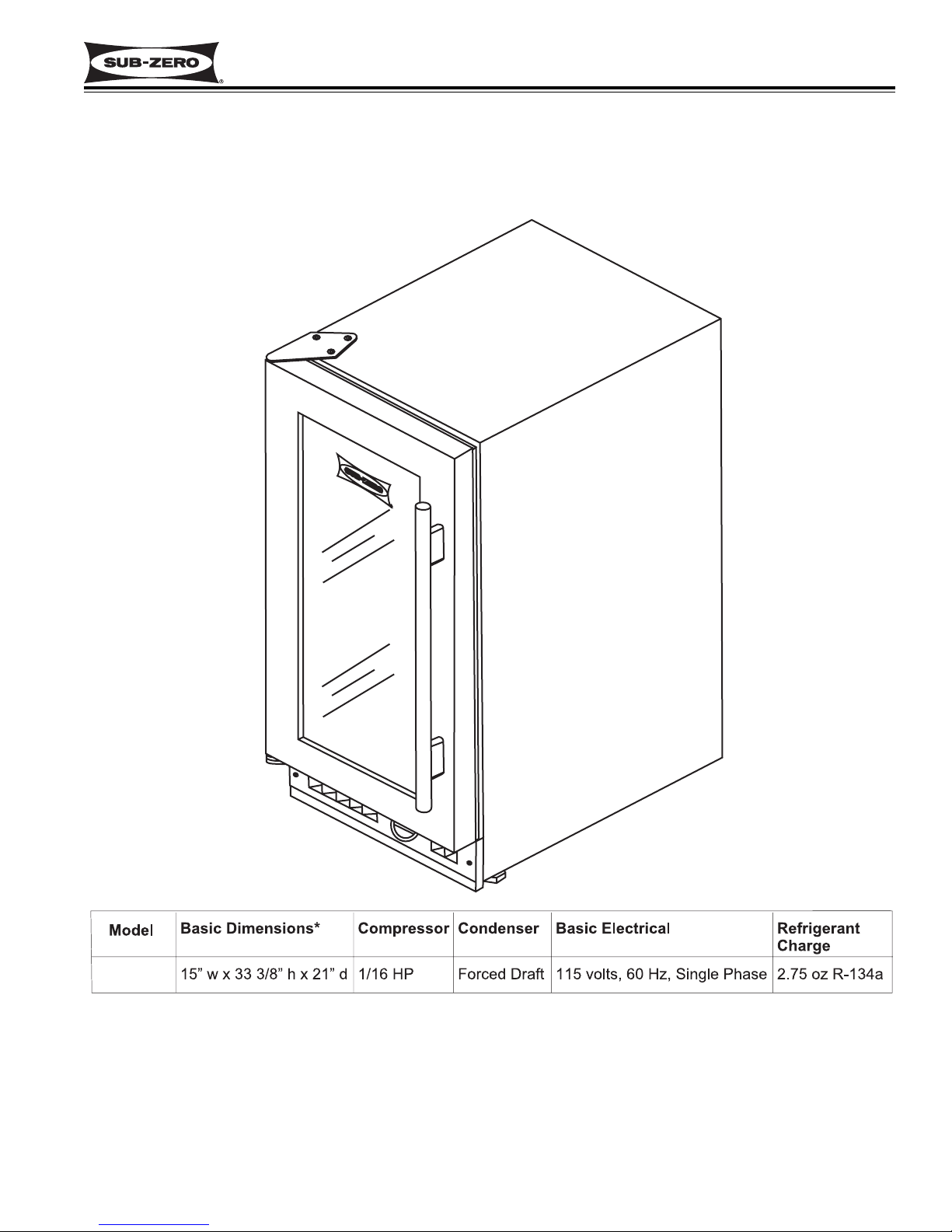
Wine Storage
Model 315W
General Information
1-1
#3758664 - First Edition - July, 2005
SECTION 1
GENERAL
INFORMATION
Page 4
General Information
Wine Storage
Model 315W
1-2
#3758664 - First Edition - July, 2005
TECHNICAL ASSISTANCE
If you should have any questions regarding the 315W
Series and/or this manual, please contact:
Sub-Zero Freezer Company, Inc.
ATTN: Service Department
P.O. Box 44988
Madison, WI 53744 - 4988
Customer Service & Parts / Warranty Claims
Phone #: (800) 222 - 7820
Technical Assistance
Phone #: (800) 919 - 8324
Customer Service & Technical Assistance
Facsimile #: (608) 441 - 5887
Parts / Warranty Claims
Facsimile #: (608) 441 - 5886
Service Department E-Mail Address:
customerservice@subzero.com
Office Hours:
7:00 AM to 7:00 PM Central Time
Monday through Friday
IMPORTANT SAFETY INFORMATION
Below are Product Safety Labels used in this manual.
The "Signal Words" used are WARNING or CAUTION.
When reviewing this manual, please note these different Product Safety Labels placed at the beginning of
certain sections of this manual. You must follow the
instructions given in the boxes of the Product Safety
Labels in order to avoid personal injury and/or product
damage.
The sample Product Safety Labels below illustrate the
precautions that should be taken when the signal word
is observed.
INTRODUCTION
This Sub-Zero Technical Service and Parts Manual (Job Aid Part #3758664) for the Model 315W is a compilation of
information provided by the Scotsman Company and has been reprinted by Sub-Zero Freezer Company, Inc., with
the permission of the Scotsman Company. This manual will provide the most recent service information about the
model 315W. This information will enable the service technician to diagnose malfunctions, perform necessary
repairs and return a model 315W unit to proper operational status.
The service technician should read the complete instructions contained in this manual before initiating any repairs on
a model 315W.
INDICATES THAT HAZARDOUS OR UNSAFE
PRACTICES COULD RESULT IN SEVERE PERSONAL INJURY OR DEATH.
Indicates that hazardous or unsafe practices could
result in minor personal injury, and/or product
damage, and/or property damage.
In addition, please pay attention to the signal word
“NOTE”, which highlights information that is especially
important for the topic being covered.
This manual is designed to be used by Authorized Service Personnel only. Sub-Zero Freezer Co., Inc.
assumes no responsibility for any repairs made on Sub-Zero refrigeration units by anyone other than
Authorized Service Technicians.
Information and images contained in this manual are the copyright property of Sub-Zero Freezer Company, Inc.
Neither this manual nor any information or images contained herein may be copied or used in whole or in part
without the express written consent of Sub-Zero Freezer Company, Inc.
© Sub-Zero Freezer Company, Inc, all rights reserved.
Page 5
Wine Storage
Model 315W
General Information
1-3
#3758664 - First Edition - July, 2005
Section 1 - General Information .................................... 1-1
Introduction ...................................................................... 1-2
Important Safety Information ............................................ 1-2
Technical Assistance ........................................................ 1-2
Table of Contents.............................................................. 1-3
Warranty Information ........................................................ 1-4
Model Description ............................................................ 1-5
Wine Storage Temperature Information............................ 1-6
Section 2 - Inst
allation Information ............................ 2-1
Pre-Installation Considerations ........................................ 2-2
Unit Dimensions .............................................................. 2-3
Installation ........................................................................ 2-4
Section 3 - Operation and Maintenance
...................... 3-1
Basic Operation ................................................................ 3-2
Loading ........................................................................ 3-2
Temperature Control .................................................... 3-2
Switching Light On or Off.............................................. 3-3
Maintenance .................................................................... 3-4
Drain System Note .......................................................... 3-5
Section 4 - Sealed System Information
........................ 4-1
HFC-134a Refrigerant Service Information ...................... 4-2
134a CAUTION ............................................................ 4-2
General Rules for Working w/134a .............................. 4-2
Sealed System Repair Procedures .................................. 4-3
Sealed System Operation ................................................ 4-4
Model 315W Refrigerant Flow Diagram .......................... 4-6
Section 5 - Component
Access / Removal
.................. 5-1
Component Access and Removal Section Explanation .. 5-2
WARNINGS & CAUTIONS .............................................. 5-2
Exterior Cosmetic and Mechanical Components ............ 5-3
Kickplate........................................................................ 5-3
Door Gasket and Door Handle .................................... 5-3
Door and Door Hinge.................................................... 5-3
Light Switch Actuator .................................................... 5-4
Back Cabinet Cover and Insulation Pack .................... 5-4
Power Cord .................................................................. 5-5
Separating Cabinet Case From Unit Base.................... 5-5
Light Switch and Plunger Switch .................................. 5-6
Thermostat .................................................................. 5-6
Interior Components ........................................................ 5-7
Wine Rack .................................................................... 5-7
Cabinet Slide and Spacer ............................................ 5-7
Light Bulb and Light Housing........................................ 5-7
Compressor Area Mechanical & Sealed System ............ 5-8
Condenser Fan Motor and Shroud .............................. 5-8
Evaporator Assembly and Filter-Drier .......................... 5-9
Compressor .................................................................. 5-10
Condenser .................................................................... 5-10
Section 6 - Part
s Lists .................................................. 6-1
Cabinet Front and Interior ................................................ 6-2
Cabinet Back .................................................................... 6-3
Condensing Unit and Electrical ........................................ 6-4
Section 7 - T
roubleshooting Guides ............................ 7-1
General Troubleshooting Guide Table of Contents .......... 7-2
General Troubleshooting Guide........................................ 7-3
Sealed System Diagnostic Information ............................ 7-5
Temperature / Low-Side Pressure Correlation.............. 7-5
Normal Operating Pressures ........................................ 7-5
Pressures Indicators .................................................... 7-5
Section 8 -T
echnical Data Tables .................................. 8-1
Model 315W Technical Data Table .................................. 8-2
Section 9 - W
iring Diagram ........................................ 9-1
Model 315W Wiring Diagram .......................................... 9-2
TABLE OF CONTENTS
Page #
Page #
Page 6
General Information
Wine Storage
Model 315W
1-4
#3758664 - First Edition - July, 2005
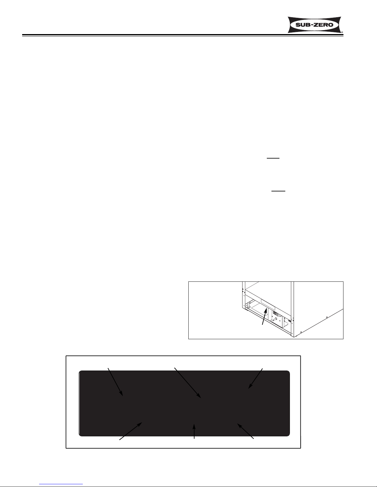
Figure 1-2. Serial Tag Layout
Figure 1-1. Serial Tag Location
315W
0000000
0.0
2.75 1.1 R134a
Jul 2005
Model Number Serial Number
Manufacture Date
Refrigerant Charge
Total Amps Refrigerant Type
Warranty Details
* Includes, but is not limited to the following:
Light Switch, Fan Motor & Blade, Drain Pan, Drain
Tube, Wiring, Light socket & bulbs, Door hinges,
Compressor Electricals, etc. . .
* Stainless Steel (Classic, Platinum & Carbon) doors,
panels and product frames are covered by a limited 60
day parts and labor warranty for cosmetic defects.
** Includes the following:
Compressors, Condenser, Evaporators, Filter-Driers,
Heat-exchangers, All Tubing that Carries the Freon.
NOTE: Condenser Fan Motors, Freon, Solder and
compressor electricals are NOT
considered sealed
system parts.
Warranty Notes
• All warranties begin at unit's initial installation date.
• All Warranty and Service information collected by SubZero is arranged and stored under the unit serial number, and the customer's last name.
Sub-Zero requests that you have the model and serial
number available whenever contacting the factory or
parts distributor.
• The serial number tag for model 315W is located on
the compartment divider, directly behind the kickplate.
(See Figures 1-1 and 1-2)
WARRANTY INFORMATION
This page summarizes the 2, 5 & 12 Year Warranty pro-
vided with every 315W Series unit, as well as two special warranties:
• Non-Residential Warranty - Applies to units installed
in non-residential applications.
• Display/Model Home Warranty - Applies to distribu-
tor or dealer display units, and units in model
homes, sold three years after date of manufacture.
Following the warranty summaries are details and notes
about the warranties.
TWO, FIVE & TWELVE YEAR Warranty
• 2 year TOTAL PRODUCT, *parts and labor.
NOTE: Stainless Steel (Classic, carBon & Platinum)
doors, panels & product frames are covered by a 60
day parts & labor warranty for cosmetic defects.
• 5 Year SEALED SYSTEM, **parts and labor.
• 6th - 12th year LIMITED SEALED SYSTEM, **parts
only.
ONE & FIVE YEAR Non-Residential Warranty
(Example: Office, Yacht, etc.)
• 1 Year TOTAL PRODUCT, *parts and labor.
NOTE: Stainless Steel (Classic, carBon & Platinum)
doors, panels & product frames are covered by a 60
day parts & labor warranty for cosmetic defects.
• 5 Year SEALED SYSTEM, **parts and labor.
ONE & FIVE YEAR Display/Model Home Warranty
(Display units sold three years after date of manufacture)
• 1 Year TOTAL PRODUCT, *parts and labor.
NOTE: Stainless Steel (Classic, carBon & Platinum)
doors, panels & product frames are covered by a 60
day parts & labor warranty for cosmetic defects.
• 5 Year SEALED SYSTEM, **parts and labor.
SERIAL TAG LOCATION
Page 7
Wine Storage
Model 315W
General Information
1-5
#3758664 - First Edition - July, 2005
MODEL DESCRIPTION
This section briefly describes the model 315W.
315W
Page 8
General Information
Wine Storage
Model 315W
1-6
#3758664 - First Edition - July, 2005
Wine Storage Unit Maximum Temperature 65° 18°
Sub-Zero Wine Storage Temperature Range, Recommended Wine Storage Temperatures
and Recommended Wine Serving Temperatures:
Bordeaux 63° 17°
Red Burgundy 61° 16°
Beaujolais 54° 12°
Sherry 52° 11°
Rosés 48° 9°
Dry White Wines 48° 9°
Champagne 46° 8°
Sweet White Wines 43° 6°
Sparkling Wines 41° 5°
Wine Storage Unit Minimum Temperature 38° 3°
Fahrenheit Celsius
The table below shows the temperature range of the Sub-Zero Wine Storage Units. This table also shows the recommended temperatures for “serving” wines. Serving wines at the recommended temperatures will insure that white
wines maintain their lively and interesting taste, and red wines will maintain their scent and flavor.
NOTE: For “long term storage” of all wines, the ideal temperature is 55°F / 13°C.
Recommended Wine Serving Temperatures
Page 9

2-1
#3758664 - First Edition - July, 2005
Wine Storage
Model 315W
Installation Information
SECTION 2
INSTALLATION
INFORMATION
Page 10
2-2
#3758664 - First Edition - July, 2005
Installation Information
Wine Storage
Model 315W
PRE-INSTALLATION CONSIDERATIONS
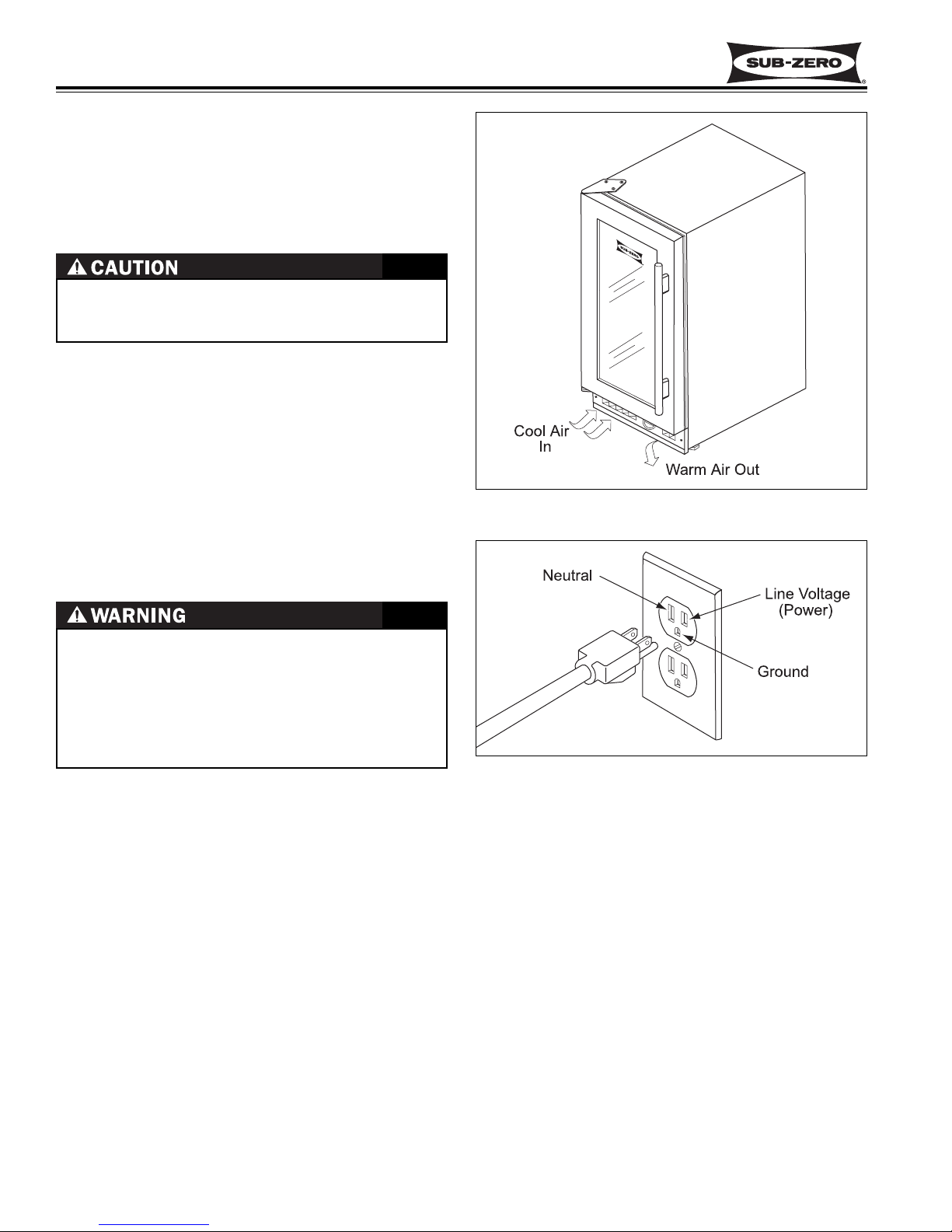
Air Flow
The model 315W uses a fan to take room air in through
the front left side of the kickplate/grille (See Figure 2-1).
Figure 2-1. Air Flow
Figure 2-2. Power Cord and Wall Outlet
Note: Follow all local, state and national codes.
Possible Need for Unit Removal
In most cases it will be necessary to pull the 315W unit
from its installation for service. For this reason, the
area under the 315W should be at the same height as
the surrounding finished floor and any decorative molding must be removable.
Moving the Unit
When the unit is moved into the house, or needs to be
removed from the house for service purposes, it is recommended to use a hand truck or dolly. Be sure to
position dolly on the side of unit and securely tape the
door shut so it will not open while transporting the unit.
• PLUG UNIT INTO GROUNDED 3-PRONG OUTLET.
• DO NOT REMOVE GROUND PRONG FROM
POWER CORD.
• DO NOT USE A 2-PRONG ADAPTER.
• DO NOT USE AN EXTENSION CORD.
FAILURE TO FOLLOW THESE INSTRUCTIONS CAN
RESULT IN FIRE, ELECTRICAL SHOCK, OR DEATH!
Airflow through the kickplate/grille must never be
obstructed. Doing so will cause a decrease in performance and possible damage to the 315W unit.
The minimum ambient air temperature the 315W will
operate in is 50°F/ 10°C, and the maximum air temperature is 100°F/ 38°C.
Electricity
The model 315W is supplied with a three prong power
cord to be plugged into a grounded wall outlet (See
Figure 2-2). The outlet should be on a branch circuit of
115 VAC, 60 Hz, single phase 15 amp, delayed action
fuse or circuit breaker. The 315W should be the only
device using that circuit.
Page 11
2-3
2-3
#3758664 - First Edition - July, 2005
Wine Storage
Model 315W
Installation Information
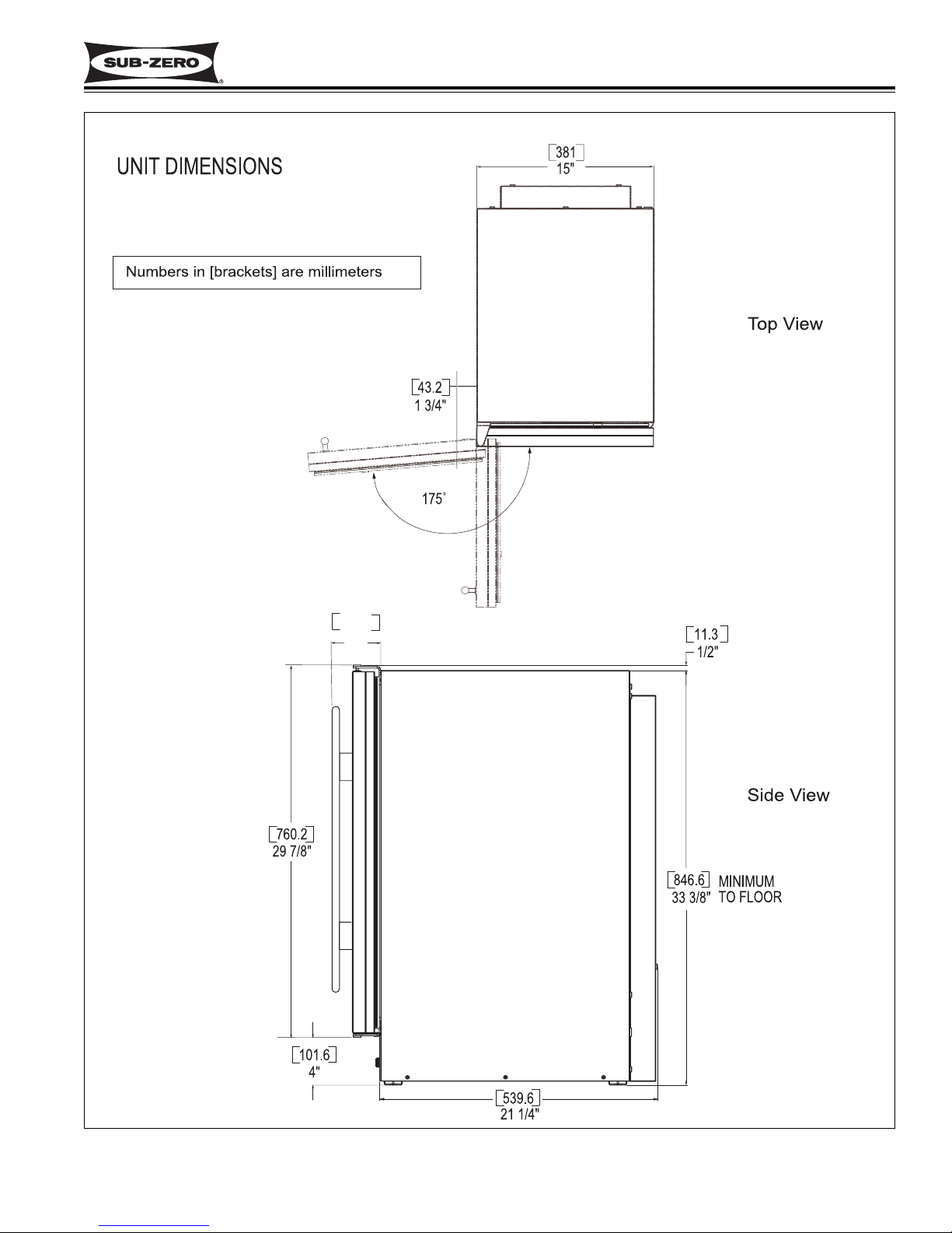
Figure 2-3. Unit Dimensions
NOTE: LEFT HAND MODEL SHOWN
101.6"
4"
Page 12
2-4
#3758664 - First Edition - July, 2005
Installation Information
Wine Storage
Model 315W
INSTALLATION
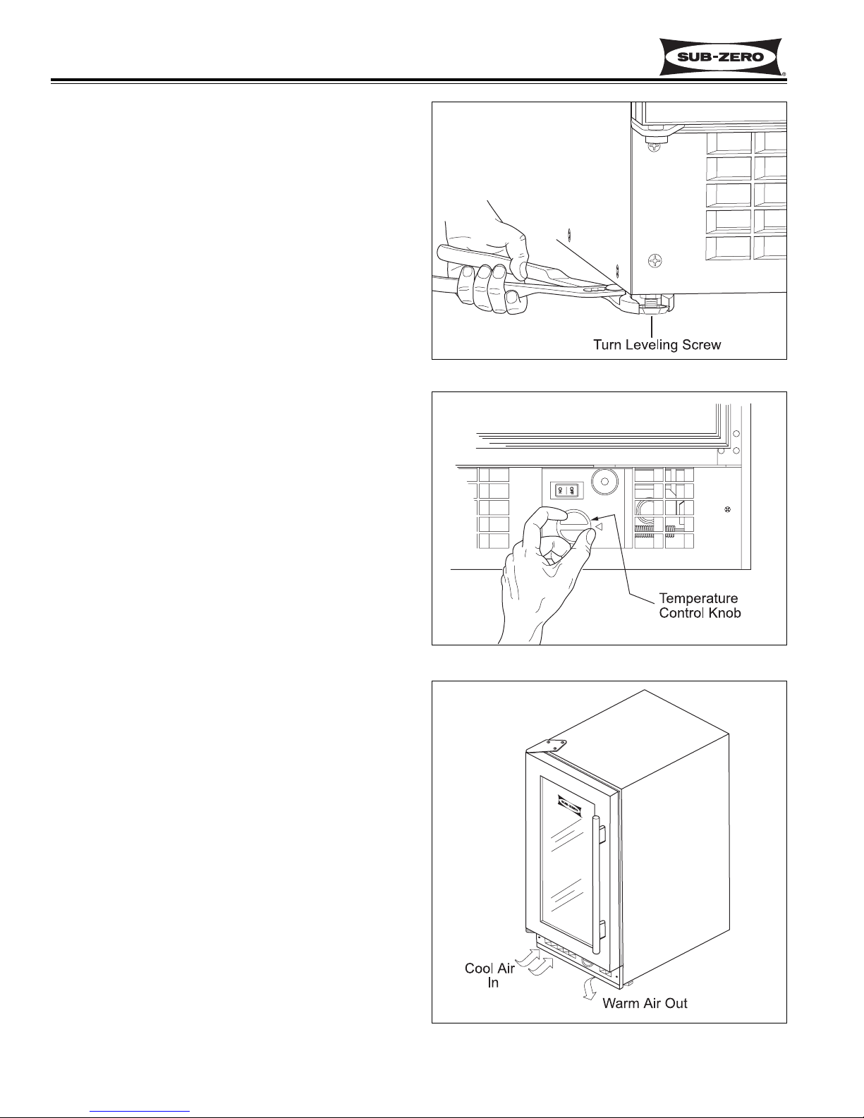
Leveling
Note: This model must be leveled prior to installation.
There are four leveler legs on a model 315W, one at
each corner. To level the unit, turn the leveler legs
counterclockwise to raise the unit or clockwise to lower
the unit. (See Figure 2-5)
If the unit is to be built in, with the electrical outlet
behind the installed location, plug unit in and slide back
into position. Check for stability and adjust legs as
needed.
If unit is free standing, move it into place and check for
stability. Adjust legs as needed. Plug unit into an electrical outlet.
Initial Start-up
When the installation is complete, be sure to remove all
tape and packing materials before initial start-up.
Locate the temperature control knob on the bottom front
of unit. Rotate knob clockwise to an operating position.
(See Figure 2-6)
You should immediately hear a humming noise and feel
air blowing in and out of the vents near the knob. (See
Figure 2-7) After 10 minutes open the door and feel the
back panel inside the cabinet. It should feel cold to the
touch.
To switch refrigeration off, rotate the temperature control knob fully counterclockwise. The light will still be
operational.
Figure 2-5. Unit Leveling
Figure 2-7. Air Flow
Figure 2-6. Temperature Control
Page 13

3-1
#3758664 - First Edition - July, 2005
Wine Storage
Model 315W
Operation and Maintenance
SECTION 3
OPERATION
AND
MAINTENANCE
Page 14
3-2
#3758664 - First Edition - July, 2005
Operation and Maintenance
Wine Storage
Model 315W
Basic Operation
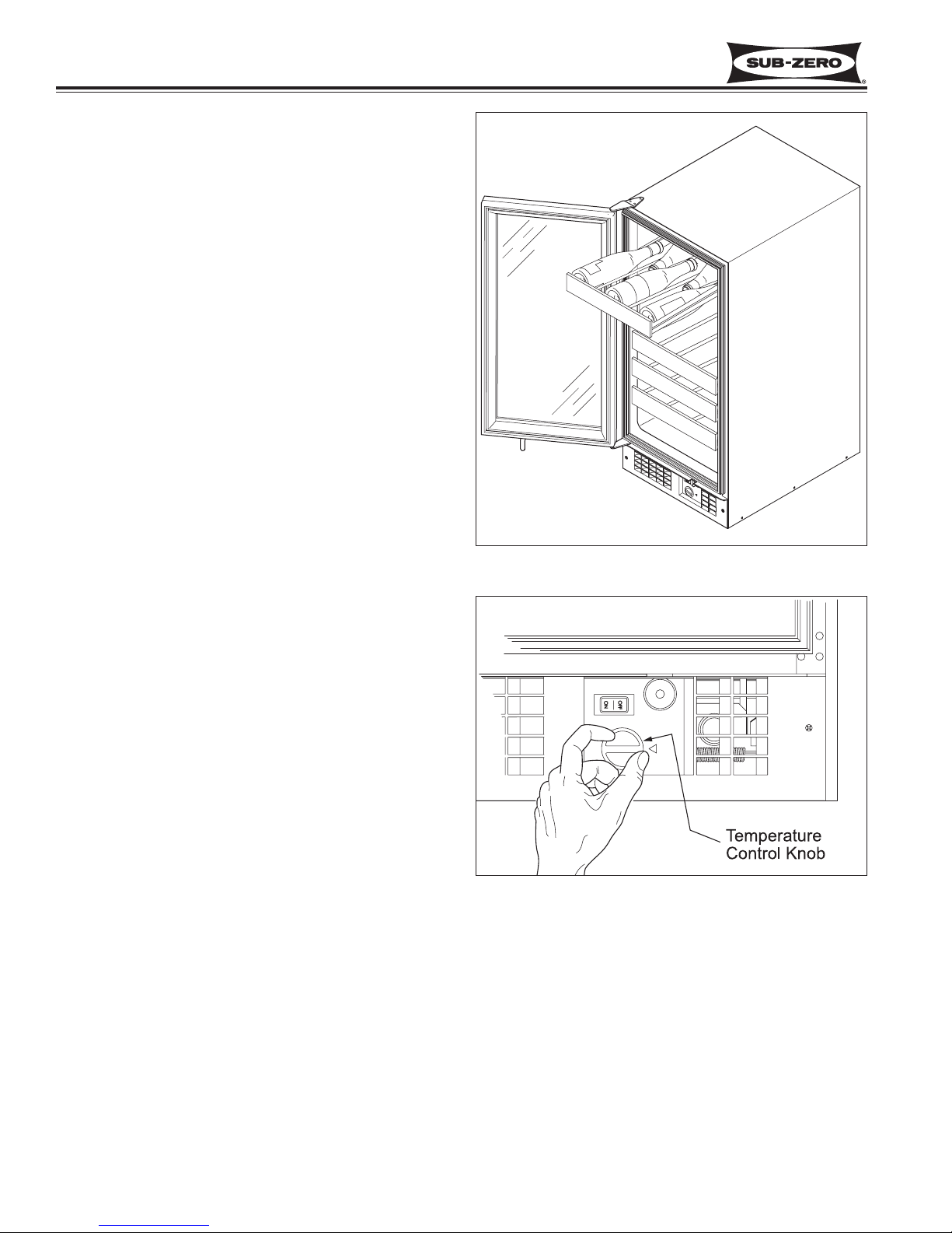
Loading
The six racks are designed to hold five bottles each
with the necks pointing toward the center. (See Figure
3-1) Two additional bottles may be placed sideways on
the bottom of the compartment for a total of 32. If large
bottles do not fit between the racks, remove an upperrack and place bottles on the rack below.
To remove a rack, remove the bottles on that rack, then
pull rack forward until it stops. Lift front of rack up while
pulling forward. After indentations on the wine rack
clear the rollers on the cabinet slides, lower front of
rack while continuing to pull forward and lifting rear of
rack out of unit.
NOTE: Loaded racks can be heavy. If several loaded
racks are pulled out at once, the unit could tip forward
unexpectedly.
Temperature Control
Rotate the temperature adjustment knob clockwise until
the desired temperature is achieved (See Figure 3-2).
Interior cabinet temperatures will be higher at the top
and front and cooler at the bottom. Place a thermometer in the compartment to check the temperatures.
Wine rack positions correspond to these temperature
ranges. The upper two racks will be the warmest, that
is where red wines would be placed. The middle two
racks are where the white wines would go, and the bottom area is where sparkling wines would be kept.
The recommended temperatures for “serving” wines
are:
• Red wines - around 60°F (16°C).
• Rosé wines - around 50°F (10°C).
• Sparkling wines - around 45°F (7°C).
NOTE: Air temperature inside the compartment will
fluctuate slightly as the cooling system cycles on and
off. In very warm room ambient conditions the unit may
run continuously.
NOTE: When initially loaded with room temperature
product, the 315W may operate continuously for as
much as 24 hours until the temperature inside the cabinet reaches the desired set-point.
Figure 3-1. Loading the 315W
Figure 3-2. Adjusting Temperature
Page 15
3-3
#3758664 - First Edition - July, 2005
Wine Storage
Model 315W
Operation and Maintenance
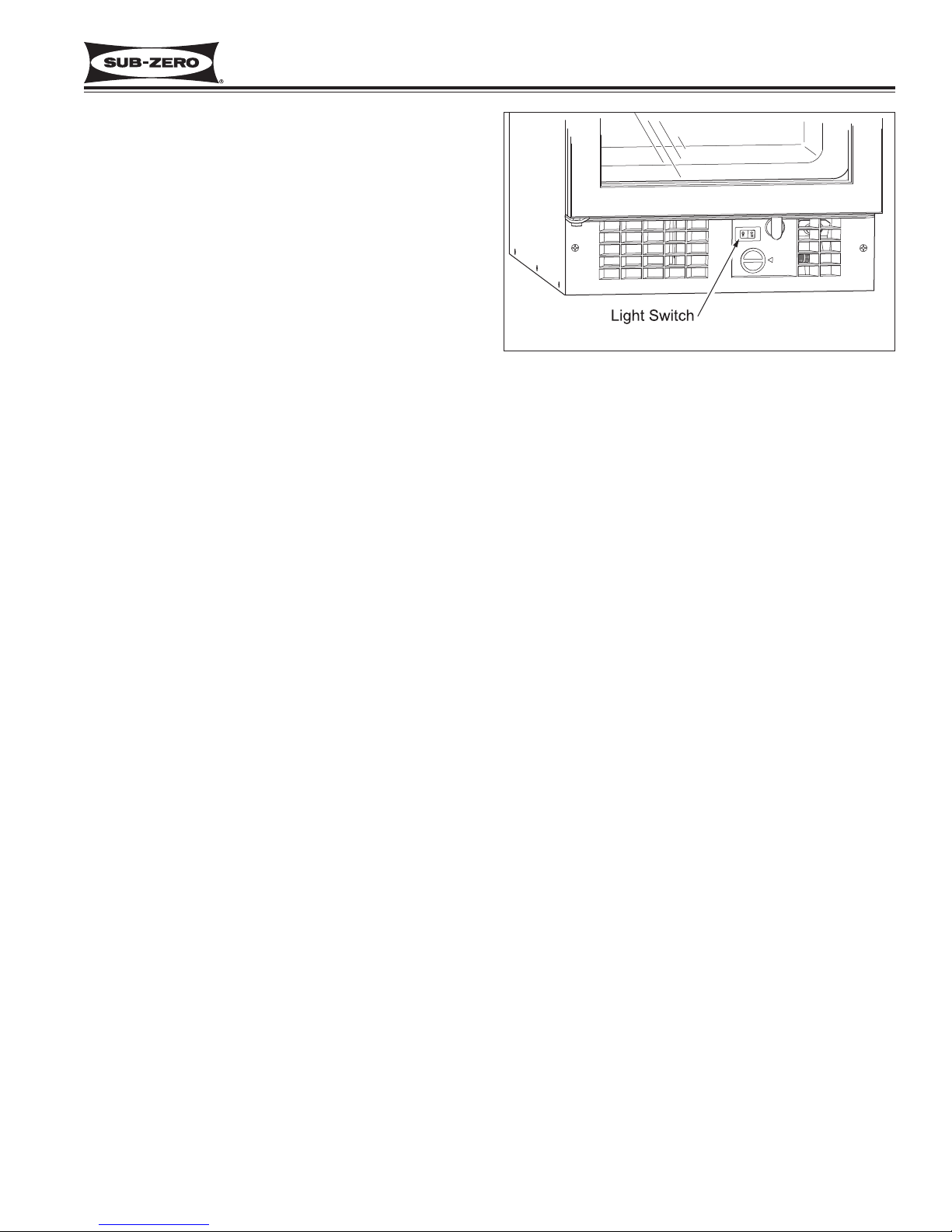
Switching Light On or Off
The display light automatically switches on when the
door is opened. To have the light on when the door is
closed, move light switch to ON position. (See Figure
3-3)
Figure 3-3. Light Switch
Page 16

3-4
#3758664 - First Edition - July, 2005
Operation and Maintenance
Wine Storage
Model 315W
MAINTENANCE
Little maintenance is required other than keeping the
unit clean. The evaporator at the back of the compartment is an off-cycle-defrost type. Any frost that develops during operation melts and drains away when the
unit cycles off. Water from the evaporator drains into a
pan at the bottom of the cabinet and evaporates into
the room air.
Routine Maintenance
The following procedures can be followed to ensure
proper operation of the 315W.
1. About once a year check the drain trough and hose
by pouring about a half-cup of water into it to be
sure it drains well. (See Figure 3-7)
2. The outside of the cabinet can be kept clean by
wiping it with mild soap and water.
3. The inside liner can be washed using any nonpetroleum based soap and water.
4. The glass door can be cleaned with any glass
cleaner.
5. The door gasket can be removed for cleaning by
pulling it out of its channel (See Figure 3-4).
6. The condenser should be vacuumed approximately
every 3 to 6 months to remove any dust or lint that
may have been drawn to it. To access the condenser, use a phillips screwdriver to remove the
kickplate. Then, use an accessory probe on the
vacuum cleaner hose to reach back into the left
side of the compressot area to remove any lint from
the front of the condenser fins. (See Figure 3-5
and Figure 3-6)
Figure 3-5. Remove Kickplate
Figure 3-6. Vacuum Fins
Figure 3-4. Door Gasket Removal
Take care to not damage the condenser fins. Doing
so will reduce the efficiency of the appliance.
Page 17

3-5
#3758664 - First Edition - July, 2005
Wine Storage
Model 315W
Operation and Maintenance
Figure 3-7. Drain System
Figure 3-8. Drain Hose
Drain System Note
The 315W has an evaperator drain system below the
evaporator. Moisture will form on evaporator panel at
the back of the unit, then during off cycles this moisture
drains into a trough and down through a hose to the
drain pan. (See Figure 3-7)
The drain hose must be directly above the drain pan or
water may leak onto the base of unit (See Figure 3-8).
Page 18

3-6
#3758664 - First Edition - July, 2005
Operation and Maintenance
Wine Storage
Model 315W
Page 19

Wine Storage
Model 315W
Sealed System Information
4-1
#3758664 - First Edition - July, 2005
SECTION 4
SEALED SYSTEM
INFORMATION
Page 20

Sealed System Information
Wine Storage
Model 315W
4-2
#3758664 - First Edition - July, 2005
HFC-134a REFRIGERANT SERVICE INFORMATION
The sealed system contains HFC-134a refrigerant. This section gives some general rules for working with 134a,
and explains procedures to be followed while servicing the sealed system.
134a refrigerant requires synthetic Ester oil in the compressor, and does not tolerate contamination from
other refrigerants, moisture, petroleum-based lubricants, silicone lubricants, cleaning compounds, rust
inhibitors, leak detection dyes, or any other type of additive.
General Rules for Working with 134a Refrigerant
• Use equipment dedicated to 134a sealed system service only.
• Use only 134a refrigerant for back-flushing and sweep charging.
• Always replace the filter-drier when servicing the sealed system.
• The filter-drier must be cut from the sealed system. Never un-braze the drier as the heat will drive moisture
back into the sealed system.
• Do not leave sealed system nor replacement compressor open to the atmosphere for more than 10 minutes.
• When the rubber plugs are pulled from the service compressor, a release of pressure should be heard. If no
release of pressure is heard, do not use the compressor.
• Use ONLY virgin 134a refrigerant when recharging the sealed system.
Page 21

Wine Storage
Model 315W
Sealed System Information
4-3
#3758664 - First Edition - July, 2005
SEALED SYSTEM REPAIR PROCEDURES
Service Procedures
a. Capture refrigerant
b. Replace compressor
c. Replace filter-drier
d. Evacuate or sweep charge system
e. Recharge system with Virgin 134a refrigerant
a. Capture refrigerant
b. Repair leak
c. Replace filter-drier
d. Evacuate or sweep charge system
e. Recharge system with Virgin 134a refrigerant
a. Capture refrigerant
b. Repair leak (if at solder joint) or replace part
c. Back flush high side of sealed system
d. If all refrigerant has escaped and system is in a vacuum, replace compressor
e. Replace filter-drier
f. Evacuate or sweep charge system
g. Recharge system with Virgin 134a refrigerant
a. Capture refrigerant
b. Repair leak (if at solder joint) or replace part
c. Back flush high side of sealed system
d. Replace compressor
e. Replace filter-drier
f. Replace heat exchanger if cap tube is clogged
g. Install a low side drier on suction line
h. Evacuate or sweep charge sealed system
i. Recharge with Virgin 134a refrigerant
a. Capture refrigerant
b. Locate and remove restriction or locate and replace part
c. Back flush high side of sealed system
d. Replace filter-drier
e. Evacuate or sweep charge system
f Recharge system with Virgin 134a refrigerant.
a. Capture refrigerant
b. Replace filter-drier
c. Evacuate or sweep charge system
d. Recharge system with Virgin 134a refrigerant
.
Problem
Non-Operating, Inefficient,
Noisy Compressor
(NOTE: To check for a nonoperating compressor, a hard
start kit can be used)
High Side leak
Low Side Leak
Contaminated System
Examples:
> Burned out compressor
> Excessive moisture from
leak in condensate loop or
in low side
> Plugged capillary tube
Restriction
(NOTE: If restriction is due to
sealed system being contaminated, see Contaminated
Sealed System above.)
Overcharge
Page 22

Sealed System Information
Wine Storage
Model 315W
4-4
#3758664 - First Edition - July, 2005
SEALED SYSTEM OPERATION
The following six diagrams represent the basic model
315W sealed system. The components are listed in
order of refrigerant flow, with an explanation of their fundamental role as part of a sealed system.
Compressor (Figure 4-1)
The compressor creates a high and low side pressure
difference in the sealed system. When the compressor
piston pushes, compressing the refrigerant gas, it causing the refrigerant pressure and temperature to rise.
The high-pressure/high-heat refrigerant gas is pushed
out the compressor discharge tube to the condenser.
Condenser (Figure 4-2)
The high-pressure/high-heat gas travels through the
condenser tubing, where most of the heat in the refrigerant is drawn out and dissipated into the room by the
cooler ambient air that is being drawn over the condenser tubing (referred to as heat transfer). This
changes the gas into a high-pressure warm liquid
before it enters the high-side filter-drier.
Filter-Drier (Figure 4-3)
The high-pressure warm liquid travels through the highside filter-drier, where the desiccant pellets inside the
drier remove moisture from the refrigerant before it
enters the capillary tube.
Figure 4-1. Compressor
Figure 4-2. Condenser
Figure 4-3. Filter- Drier
FILTER-DRIER
COMPRESSOR
CONDENSER
Page 23

Wine Storage
Model 315W
Sealed System Information
4-5
#3758664 - First Edition - July, 2005
Capillary Tube (Figure 4-4)
The high-pressure warm liquid refrigerant travels
through the long skinny capillary tube which is soldered
to the suction tube (these two tubes soldered together
create the heat exchanger). (See Suction Tube & Heat
Exchanger below.) As the warm liquid refrigerant trav-
els through the capillary tube it gives up heat to the cool
refrigerant gas traveling through the suction tube and
the pressure drops, so it is a low-pressure/cool liquid
before it enters the evaporator.
Evaporator (Figure 4-5)
As the low-pressure/cool liquid refrigerant enters the
evaporator, it vaporizes. This is caused by a dramatic
pressure change, occurring when the refrigerant from
the smaller diameter capillary tubing enters the larger
diameter evaporator tubing. This refrigerant vapor travels through the evaporator, absorbing heat from the
compartment, gradually converting the refrigerant to a
cool gas. This cool refrigerant gas then enters the suction tube.
Suction Tube & Heat Exchanger (Figure 4-6)
The cool gas travels through the suction tube which is
soldered to the capillary tube (as mentioned earlier,
these two tubes soldered together create the heat
exchanger). As this cool refrigerant gas travels through
the suction tube it absorbs heat from the warm liquid
refrigerant traveling through the capillary tube, making it
a luke warm gas. The lukewarm refrigerant gas is
pulled back to the compressor (via vacuum force),
where the process begins again.
Figure 4-4. Capillary Tube(s)
Figure 4-5. Evaporator(s)
Figure 4-6. Suction Line & Heat Exchanger
SUCTION
TUBE
HEAT
EXCHANGER
CAPILLARY
TUBE
EVAPORATOR
Page 24

Sealed System Information
Wine Storage
Model 315W
4-6
#3758664 - First Edition - July, 2005
REFRIGERANT FLOW DIAGRAM
Figure 4-7. Model 315W Refrigerant Flow
HEAT EXCHANGER
EVAPORATOR
PLATE
HIGH-SIDE
FILTER-DRIER
COMPRESSOR
CONDENSER
Page 25

Component Access / Removal
5-1
#3758664 - First Edition - July, 2005
Wine Storage (315W) Series
SECTION 5
COMPONENT ACCESS
AND REMOVAL
Page 26

Component Access / Removal
Wine Storage
Model 315W
5-2
#3758664 - First Edition - July, 2005
COMPONENT ACCESS AND REMOVAL
This section explains how to adjust, access and remove components from a model 315W.
This section is arranged as follows:
• EXTERIOR COSMETIC AND MECHANICAL COMPONENTS
• INTERNAL COMPONENTS
• SEALED SYSTEM COMPONENTS
An attempt has been made to arrange these procedures in such a way as to simulate which components would
need to be removed first in order to gain access to other components. When following a component removal procedure, it may be necessary to reference another component removal procedure listed earlier in this section.
NOTE: Before continuing, take note of the WARNINGS and CAUTIONS below.
• TO AVOID ELECTRIC SHOCK, POWER TO THE UNIT MUST BE DISCONNECTED WHENEVER ACCESS-
ING AND/OR REMOVING COMPONENTS POWERED BY ELECTRICITY OR COMPONENTS NEAR OTHER
ELECTRICAL COMPONENTS.
• IF REMOVING A DOOR FROM A UNIT, REMEMBER THAT DOORS ARE HEAVY. IF THEY WERE TO FALL,
THEY COULD CAUSE SERIOUS PERSONAL INJURY.
• If working in the compressor area, be aware that compressor and tubing may be hot.
• If working on or around the condenser, be aware that condenser fins are sharp.
Page 27

Wine Storage
Model 315W
Component Access / Removal
5-3
#3758664 - First Edition - July, 2005
Figure 5-1. Kickplate Removal
Figure 5-3. Door and Hinge Removal
EXTERIOR COSMETIC AND MECHANICAL
COMPONENTS
Kickplate
The kickplate, located under the door assembly, is vented to allow air flow through the compressor area.
To remove the kickplate (See Figure 5-1):
1. Open door.
2. Pull temperature control knob from thermostat
shaft.
3. Extract the mounting screws from each end of kick-
plate and pull kickplate forward.
Door Gasket and Door Handle
The door gasket is held in place by pressing the spline
of the gasket into a channel in the door assembly.
The door handle is secured to the door with screws that
pass through the door assembly and standoffs, into the
handle. The heads of thee screws are hidden in the
gasket channel, covered by the gasket.
To remove a gasket and/or handle (See Figure 5-2):
1. Open door.
2. Pull door gasket from channel of door.
3. Extract the door handle mounting screws and pull
the handle and standoffs from the door.
Door and Door Hinge
To remove the door and hinges (See Figure 5-3):
1. Open door so door hinge mounting screws are visi-
ble.
2. Extract bottom door hinge mounting screws.
3. While holding door assembly, extract top door hinge
mounting screws.
4. Remove door assembly from unit.
NOTE: When removing the door, be aware of the
spacer bushings between the hinge and door
assembly so they are not lost.
5. Remove the cabinet hinges by extract the screws
securing the hinges to the unit frame.
NOTE: Depending on unit installation, it may be
necessary to extract unit from its installed position
to access the cabinet hinge screws.
Figure 5-2. Door Handle and Gasket Removal
Door Handle
Page 28

Component Access / Removal
Wine Storage
Model 315W
5-4
#3758664 - First Edition - July, 2005
Light Switch Actuator
The light switch actuator is attached to the bottom of
the door assembly with screws. To remove the actuator
(See Figure 5-4):
1. Open door.
2. Extract screws securing switch actuator to door
frame.
Back Cabinet Cover and Insulation Pack
NOTE: Electrical shock hazard, take note of WARNINGS and CAUTIONS on page 5-2.
In order to remove components from the back of the
unit, the appliance will need to be removed from its
installation site.
To remove the back cover and insulation pack (See
Figure 5-5):
1. Extract screws from the back cover securing it to
the cabinet case.
2. Remove back cover with the baffle and the insulation pack.
Figure 5-4. Light Switch Actuator Removal
Figure 5-5. Back Cover Removal
Cabinet Case
Insulation
Pack
Back
Cover
Baffle
Page 29

Wine Storage
Model 315W
Component Access / Removal
5-5
#3758664 - First Edition - July, 2005
Power Cord
NOTE: Electrical shock hazard, take note of WARNINGS and CAUTIONS on page 5-2.
The power cord is located at the right rear of the unit.
To access the power cord, the unit will need to be
moved out from its installation position. The back cover
and insulation pack must be removed first, then, (See
Figure 5-6):
1. With a flat bladed screwdriver remove electrical
cover from rear of unit.
2. Disconnect wire leads.
3. Remove power cord strain relief from cabinet case
and extract cord from unit.
Separating Cabinet Case from Unit Base
In order to access components located in the compressor area, the cabinet case must be separated from the
unit base.
NOTE: The cabinet case cannot be completely separated from the unit base unless the heat exchanger is
severed.
To separate cabinet case from unit base (See Figure 5-
7):
1. Remove door assembly, wine racks, and back
cover with the insulation pack.
NOTE: Removal of the door and wine racks is recommended for safety and for weight reduction
when lifting and separating the cabinet.
2. Extract screws from bottom sides of cabinet case.
3. The cabinet case may be separated two ways.
a. For servicing the light switch, thermostat, or
drain pan, it may only be necessary to use a
spacer (a piece of 2x4 lumber works well) to lift
the front of the cabinet case enough to allow
access.
b. For servicing the sealed system, the case may
be removed from the unit base by carefully lifting the cabinet case above the sealed system
components mounted to the unit base, and
turning the case to the right.
Figure 5-7. Cabinet Case Removal
Figure 5-6 Power Cord Removal
When lifting and turning the cabinet case, be
mindful of the sealed system components so
they are not crimped or damaged.
Cabinet Case
Insulation
Pack
Back
Cover
Remove Electrical
Cover
Remove Screws
Baffle
Cabinet Case
Page 30

Component Access / Removal
Wine Storage
Model 315W
5-6
#3758664 - First Edition - July, 2005
Light Switch and Plunger Switch
NOTE: Electrical shock hazard, take note of WARNINGS and CAUTIONS on page 5-2.
The switches are inserted into a bracket located behind
the kickplate at the bottom front of unit.
To remove the light switch or plunger switch, the unit
must be pulled from its installation and the kickplate
must be removed first, then (See Figure 5-8):
1. From the bottom of the appliance, extract the
screws that secure the bracket and pull the bracket
forward.
2. Disconnect wire leads from switch.
3. Depress retaining clips at sides of switch and push
switch out through mounting bracket.
Thermostat
NOTE: Electrical shock hazard, take note of WARNINGS and CAUTIONS on page 5-2.
The thermostat is attached to a bracket located behind
the kickplate at the bottom front of unit. The thermostat
bulb runs to the rear of the unit, up the back and into
the refrigerated compartment. The coiled end of the
thermostat bulb is attached to the bottom rear of the
evaporator plate with a bracket and screws.
To remove the thermostat, the unit must first be pulled
from its installation, and the back cabinet cover, as well
as the kickplate must be removed, then (See Figure 5-
8):
1. From inside unit:
a. Extract screws securing the thermostat bracket
to bottom rear of the evaporator.
b. Pull coiled end of thermostat bulb from the
compartment.
2. At bottom of unit:
a. Extract the screws that secure the bracket to
the base and pull bracket forward.
b. Disconnect wire leads from thermostat and pull
thermostat bulb toward front of unit.
Figure 5-8. Light Switch, Plunger Switch and
Thermostat Removal
Rocker
Switch
Plunger
Switch
Bracket
Thermostat
Page 31

Wine Storage
Model 315W
Component Access / Removal
5-7
#3758664 - First Edition - July, 2005
Figure 5-9. Wine Rack Assembly Removal
Figure 5-10. Slide and Spacer Removal
Figure 5-11 . Light Bulb and Housing Removal
INTERNAL COMPONENTS
Wine Racks
To remove a wine rack assembly (See Figure 5-9):
1. Pull rack forward until it stops.
2. Lift front of rack up while pulling forward.
3. After indentations on the wine rack clear the rollers
on the cabinet slides, lower front of rack while continuing to pull forward and lifting rear of rack.
Cabinet Slide and Spacer
Cabinet slides are attached to the side walls with
screws. On the handle side, a narrow plastic spacer sits
between the slide and side wall. On the hinge side, a
wide plastic support spacer sits between the slide and
wall.
To remove a cabinet slide, the wine rack must be
removed first, then extract the Phillips head mounting
screws and pull the slide and slide spacer from the wall.
(See Figure 5-10)
Light Bulb and Light Housing
The light bulb is located at the inside top of the appliance and is protected by the light housing.
NOTE: Electrical shock hazard, take note of WARNINGS and CAUTIONS on page 5-2.
To remove the light bulb and light housing. (See Figure
5-11)
1. Remove top wine rack.
2. Pull electrical plug from socket at top of the com-
partment.
3. Remove the bulb from holder.
4. If bulb housing needs to be replaced, extract
screws securing bulb housing to the top of the compartment.
Extract
Screws
Spacer
Extract Screws
Page 32

Component Access / Removal
Wine Storage
Model 315W
5-8
#3758664 - First Edition - July, 2005
Condenser Fan Motor and Fan Shroud
The condenser fan motor is located at the left rear corner of the unit tray, and is held in place with screws
passing up from under the unit tray into the condenser
fan motor mounting brackets.
To access the condenser fan motor, the unit will need to
be pulled from its installation, and the cabinet case separated from the unit base, then (See Figure 5-12):
1. Disconnect condenser fan motor wire leads.
2. Extract mounting screws from condenser fan bracket, then lift condenser fan motor assembly off of unit
base
3. Extract mounting screws securing condenser fan
shroud to condenser, then pull fan shroud off of unit
base.
4. To remove fan blade from fan motor, extract locking
nut from fan motor shaft and pull fan blade from fan
motor shaft.
Figure 5-12. Condenser Fan Motor Removal
COMPRESSOR AREA MECHANICAL & SEALED SYSTEM COMPONENTS
&
NOTE: To remove any sealed system component, the unit must be pulled from its installation.
NOTE: Always replace the high-side filter-drier when servicing the sealed system.
NOTE: Due to the limited access under the 315W, it will be necessary to separate the cabinet case from the unit
base to access components in the compressor area.
Page 33

Wine Storage
Model 315W
Component Access / Removal
5-9
#3758664 - First Edition - July, 2005
Evaporator Assembly and Filter-Drier
The evaporator assembly consists of the evaporator
and heat exchanger. The evaporator is mounted to the
inside rear wall of unit. The heat exchanger is routed
out the back wall, down to the unit tray where the capillary tube is connected to the high-side filter-drier and
the suction tube is attached to the compressor suction
port.
To remove an evaporator assembly (See Figures 5-13,
5-14, 5-15):
1. Evacuating refrigerant from sealed system.
2. From back of the unit use a tin snips or similar tool
to cut heat exchanger as close to back wall as possible.
3. Extract screws securing evaporator to rear wall of
refrigerated compartment, then pull evaporator from
compartment.
4. With a tube-cutter, cut filter-drier from condenser
outlet, and suction tube from compressor.
NOTE: After new evaporator assembly is installed,
the tubing channel must
be sealed shut with sili-
cone.
Figure 5-13. Cut Heat Exchanger
Figure 5-15. Cut Drier Inlet & Outlet
Figure 5-14. Evaporator Removal
Cut Here
Evaporator
Extract
Screws
Condenser
Filter-Drier
Cut Here
Page 34

Component Access / Removal
Wine Storage
Model 315W
5-10
#3758664 - First Edition - July, 2005
Compressor
NOTE: Always replace the high-side filter-drier when
servicing the sealed system.
NOTE: Due to the limited access under the 315W, it
will be necessary to separate the cabinet case from the
unit base to access components in the compressor
area.
The compressor is located at the back of the unit base.
To access the compressor, the unit will need to be
pulled from its installation.
With unit out of installation and case separated from
unit base (See Figures 5-16):
1. Disconnect compressor electricals.
2. With a tube-cutter, cut suction tube and discharge
tube approximately 1-1/2" from compressor.
3. Remove cotter pins and washers from compressor
mounting brackets, then lift compressor off of
mounting brackets.
Condenser
NOTE: Always replace the high-side filter-drier when
servicing the sealed system.
NOTE: Due to the limited access under the 315W, it
will be necessary to separate the cabinet case from the
unit base to access components in the compressor
area.
The condenser is located on the left side of the unit
base, and is held in place with screws passing up from
under unit base into the condenser mounting brackets.
To access the condenser, the unit will need to be pulled
from its installation, and the cabinet case separated
from the unit base, then, (See Figure 5-17):
1. With a tube-cutter, cut inlet tube and outlet tube
approximately 3" from the condenser.
2. Extract condenser mounting screws from unit base
and from side brackets.
3. Extract screws securing the condenser fan shroud
to the condenser and remove fan shroud.
Figure 5-17. Condenser Removal
Figure 5-16. Unit Tray Component Access
Compressor
Hitch Pin and
Washer
Mounting
Unit Base
Grommet
Bracket
Condenser
Fan Shroud
Condenser
Cut
Here
Extract
Screws
Page 35

Wine Storage
Model 315W
Parts Lists & Exploded Views
6-1
#3758664 - First Edition - July, 2005
SECTION 6
PARTS LISTS &
EXPLODED VIEWS
Page 36

Parts Lists & Exploded Views
Wine Storage
Model 315W
6-2
#3758664 - First Edition - July, 2005
CABINET FRONT AND INTERIOR PART LIST
Ref #
Part # Description
1. 4135480 Door Assy, Glass 315W/O
4135491 Door Assy, Glass 315W/S-RH
4135492 Door Assy, Glass 315W/S-LH
0880831 Skin, Door Glass-RH,SS
0880832 Skin, Door Glass-LH,SS
3512030 Handle, Door SS 3/4X24.188
6110790 Screw, Mach #10-24X1-3/4 Pan HD (Qnty. 2)
3512190 Standoff, SS Oval (Qnty. 2)
2. 03386301 Spacer-Hinge-SS Door (Qnty.4)
3. 6110540 Bolt, #10-24 x 1/2" Flat Socket HD Silver (Qnty 10)
4. 13094201 Door Gasket
5. 3541121 Hinge, Cabinet Top Assy Black
3541122 Hinge, Cabinet Top Assy Silver
6. A38846001 Aluminum Bracket
7. 12288801 Bulb
8. 03386901 Aluminum Clamp (Qnty. 2)
9. 03173001 Nylon Washer (Qnty. 2)
10. 03140419 Thread Forming Screw
11. 6200721 Screw, #8-18X1/2 Ph Low Prfl, B
12. 02404701 Kickplate- SZ-WSU-RH
02404702 Kickplate- SZ-WSU-LH
13. 02404601 Control Knob
14. A38495001 Bracket-Door Strike
15. 03143100 Screw #10 (Qnty. 2)
16. 02404901 Hinge Assy, Bottom RH
02404902 Hinge Assy, Bottom LH
17. 6220320 Screw Grommet
18. A38491001 Skirt-Kick plate
19. 03153101 Screw Thread Form Tapping (Qnty. 2)
20. A38413001 Bracket T-Stat Bulb
21. 03140412 Screw, Thread forming (Qnty.2)
22. 02398701 Trough
23. 18887621 Evaporator
24. 03140419 Thread Forming Screw (Qnty. 4)
25. 02250501 Spacer (Qnty. 4)
26. 02400901 Insulation, Evap. Tubing
27. 02405601 Glides-Drawer (Qnty. 6)
28. 02405101 Spacer-Wide (Hinge Side) (Qnty. 6)
02405201 Spacer-Narrow (Handle Side) (Qnty. 6)
29. 03385401 Screw, #8 with #7 Head, 7/8” (Qnty. 12)
30. 02405601 Glides-Drawer (Qnty. 6)
31. 02405101 Spacer-Wide (Hinge Side) (Qnty. 6)
02405201 Spacer-Narrow (Handle Side) (Qnty. 6)
32. 03385402 Screw, #8 with #7 Head, 1-3/8” (Qnty. 12)
33. 02405501 Moulding-Wood (Qnty. 6)
34. 02405601 Glides-Drawer (Qnty. 6)
35. 03385701 Pop Rivet 5/8 Flat Head (Qnty. 24)
36. 02405601 Glides-Drawer (Qnty. 6)
37. 02405401 Shelf (Qnty. 6)
38. 03140439 Screw Thread Cutting (Qnty. 12)
39. 03141830 Screw, Flathead Machine
40. 02405901 Bracket Hinge mount, RH
02405902 Bracket Hinge mount, LH
41. 03143100 Screw #10 (Qnty.3)
Page 37

Wine Storage
Model 315W
Parts Lists & Exploded Views
6-3
#3758664 - First Edition - July, 2005
CABINET FRONT AND INTERIOR
1
2
3
5
41
6
24
25
23
26
19
20
22
15
4
31
32
29
30
27
39
14
40
16
12
13
11
28
17
18
10
33
8
9
7
37
38
35
36
34
Page 38

Wine Storage
Model 315W
6-4
#3758664 - First Edition - July, 2005
Part Lists & Exploded Views
CABINET BACK
Ref # Part # Description
1. NA Assy, Cabinet, Foamed
2. 02325601 Insulation Bag
3. A35546001 Back Panel
4. 03140408 Screw, PH#8X3/8 (Qnty. 5)
5. A35547001 Baffle
6. 12163817 Power Cord
7. 12062908 Bushing
8. 03141926 Self Tapping Type AB Screw (Qty. 6)
9. A38406001 Assy, Suction Line
9
Page 39

Wine Storage
Model 315W
Parts Lists & Exploded Views
6-5
#3758664 - First Edition - July, 2005
CONDENSING UNIT AND ELECTRICALS
Ref # Part # Description
1. 18880221 Compressor Package
18880251 Relay
18880252 Overload
2. 03382101 Hitch Pin (Qnty. 4)
3. 03140708 Washer Type A Plain (Qnty. 4)
4. 12292701 Fan Motor (1.0 Watt 115V)
5. A28798001 Bracket, Fan Motor
6. 02419701 Fan Blade
7. 02287101 Shroud, Fan
8. 18886101 Grommet (Qnty. 4)
9. 12121310 Bushing
10. 13067402 Tubing-Per FT.
11. A38408001 Bracket-Drain Tube
12. 02398401 Drain Pan
13. 02349001 Drier
14. A29015001 Bracket, Compressor Mount (Qnty. 2)
Ref # Part # Description
15. A38638002 Base Panel
16. 03160801 Leveler Leg (Qnty. 4)
17. 03153101 Screw Thread Form Tap (Qty. 21)
18. A38407001 Bracket-T-Stat
19. 12288601 Plunger Switch
20. 11054721 Thermostat
21. A35495001 Divider Panel
22. 18871201 Condenser
23. 19050302 Insulation Tape
24. A35512001 Baffle-Air Dam
25. 12288501 Rocker Switch
26. A35550001 Bracket, Drier
27. NA Tube, Discharge
28. NA Tube, Hi Side Process
29. NA Tube, Condenser to Drier
Page 40

Parts Lists & Exploded Views
Wine Storage
Model 315W
6-6
#3758664 - First Edition - July, 2005
Page 41

Wine Storage
Model 315W
Troubleshooting
7-1
#3758664 - First Edition - July, 2005
SECTION 7
TROUBLESHOOTING
Page 42

Troubleshooting
Wine Storage
Model 315W
7-2
#3758664 - First Edition - July, 2005
General Troubleshooting Guide
The Table of Contents below indicates how the General Trouble Shooting Guide is arranged.
1. As close as possible, match the complaint, or description of the problem the unit is experiencing, with those in
the table of contents below.
2. To the left of the problem description below, take note of the letter.
3. Locate that letter in the left column of the General Troubleshooting Guide.
a. In the center column of the General Troubleshooting Guide is a list of possible causes for the problem.
b. The information in the right column explains what tests and/or corrective actions to perform.
Ltr
Problem Description Page #
A. Warm Temperatures and/or Unit Runs too Long .......................................................................................................... 7-3
B. Thick Frost On Evaporator .................................................................................................................................................. 7-3
C. Noise .................................................................................................................................................................................. 7-4
D. Lighting Not Working Properly ........................................................................................................................................ 7-4
E. Water Running From Inside Cabinet .............................................................................................................................. 7-4
F. Water Under Appliance .................................................................................................................................................... 7-4
G. Unit Not Level .................................................................................................................................................................... 7-4
Page 43

A. Warm Temperatures and/or
Unit Runs too Long
B. Thick Frost On Evaporator
Unit Switched Off
Temperature Control Out of
Adjustment
Unit Recently Energized
Unit Recently Stocked with Wine
High Room Ambient Temperature
and/or Unit in Direct Sunlight
Door Ajar
a. Wine Rack Obstruction
b. Door out of Adjustment
c. Door or Cabinet Hinge Problem
d. Door Gasket Not Tight
Condenser Air Flow / Fan Fault
a. Dirty Condenser
b. Fan Blade Loose or Obstructed
c. Fan Motor Disconnected or
Malfunctioning
Thermostat Fault
Compressor Fault
a. Compressor Electricals Disconnected
or Malfunctioning or Compressor
Inefficient, or Locked
Sealed System Leak or Restriction
Door Ajar
a. Wine Rack Obstruction
b. Door out of Adjustment
c. Door or Cabinet Hinge Problem
d. Door Gasket Not Tight
Thermostat Not Keeping Unit Off Long
Enough.
Sealed System Leak
Check Temperature Control
Check adjustment.
Allow time for unit to cool down.
Allow unit many hours to cool warm product.
Instruct Customer unit performs best between
60°F (16°C) - 90°F (32°C), no direct sunlight.
a. Adjust wine rack
b. Adjust door.
c. Check hinges. Replace if defective.
d. Check gasket fit. Replace if needed.
a. Check/clean condenser.
b. Tighten blade or move obstruction.
c. Check fan motor operation. Check fan
motor electrical connections back to compressor. Check for 115V AC from fan
motor to compressor. Reconnect or repair
wires, or replace motor if defective.
Replace thermostat if defective.
a. Check integrity of compressor electricals.
Correct wiring problems or replace compressor electricals if defective.
b. Check AMP draw on compressor. If high
by 15% or more, replace compressor.
SEE SEALED SYSTEM DIAGNOSTIC
INFORMATION
a. Adjust wine rack
b. Adjust door.
c. Check hinges. Replace if defective.
d. Check gasket fit. Replace if needed.
Thermostat should cut-in ~ 44°F (7°C) evaporator temperature. Cut-out temperature will
vary. Tighten thermostat bracket at bottom of
evaporator plate, or replace thermostat if
defective.
SEE SEALED SYSTEM DIAGNOSTIC
INFORMATION
PROBLEM POSSIBLE CAUSE TEST / ACTION
Wine Storage
Model 315W
Troubleshooting
7-3
#3758664 - First Edition - July, 2005
Page 44

PROBLEM POSSIBLE CAUSE TEST / ACTION
Troubleshooting
Wine Storage
Model 315W
7-4
#3758664 - First Edition - July, 2005
C. Noise
D. Lighting Not Working
Properly
E. Water Running From Inside
Cabinet
F. Water Under Appliance
G. Unit Not Level
Condenser Fan Noise
Fan Blade Contacting Shroud
Light Bulb Burned Out
Wiring or Bulb Socket Fault
Door Switch Does Not Close
Cannot Switch Lights On With Door
Closed
Drain Trough Hose Plugged
Drain Trough Hose Plugged
Drain Hose Out of Position
Drain Pan Over-filling
Legs Out of Adjustment
May be normal. Check for noises made from
vibration.
Check for free fan blade rotation. Adjust or
replace components as needed.
Replace bulb.
Check bulb socket and wiring. Repair or
replace components as needed.
Check door switch and switch actuator align-
ment. Add, adjust or replace as needed.
Check switch, replace if defective.
Check rocker switch. Replace if defective.
Clean hose, replace if damaged. Clean trough
Clean hose, replace if damaged. Clean trough
Drain hose must be directly over drain pan.
Adjust positioning of hose and/or drain pan.
Check door and door gasket for proper fitting.
Adjust as needed, replacing defective parts.
Turn legs until unit is level and secure.
Page 45

SEALED SYSTEM DIAGNOSTIC INFORMATION
NOTE: The temperature/pressure table at right is for reference only. A
unit's temperature/pressure correlation may differ from those listed due
to: set-points, where the sealed system is in the refrigeration cycle,
ambient temperature, etc.
If a unit is experiencing temperature problems, it is recommended to
reference the General Troubleshooting Guide before accessing the
sealed system. After all mechanical and electrical components have
been ruled out, sealed system pressures can be checked and compared against those listed in the tables below.
NOTE: Whenever entering the sealed system, always use solder
-on
process valves. Do NOT use bolt-on process valves as they are prone
to leak.
NOTE: Whenever servicing the sealed system, the high-side filter-drier
assembly must be replaced.
NORMAL OPERATING PRESSURES
Model
315W
Normal Low Side Pressures
0 psi to 38 psi
Normal High Side Pressures
90 psi to 115 psi
PRESSURE INDICATIONS
If low side pressure is
NORMAL
LOW
LOW
HIGH
HIGH
& high side pressure is
NORMAL
LOW
HIGH
LOW
HIGH
possible problem is
MECHANICAL
(see General Troubleshooting Guide)
LEAK
RESTRICTION
INEFFICIENT COMPRESSOR
OVER CHARGE
TEMPERATURE / LOW-SIDE PRESSURE CORRELATION
Pressure
10” Vac
7” Vac
4” Vac
0” Vac
2 Psi
4 Psi
7 Psi
9 Psi
12 Psi
15 Psi
18 Psi
22 Psi
26 Psi
30 Psi
35 Psi
40 Psi
45 Psi
51 Psi
57 Psi
64 Psi
71 Psi
78 Psi
Temperature
-30°F (-34°C)
-25°F (-32°C)
-20°F (-29°C)
-15°F (-26°C)
-10°F (-23°C)
-5°F (-21°C)
0°F (-18°C)
5°F (-15°C)
10°F (-12°C)
15°F (-9°C)
20°F (-7°C)
25°F (-4°C)
30°F (-1°C)
35°F (2°C)
40°F (4°C)
45°F (7°C)
50°F (10°C)
55°F (13°C)
60°F (16°C)
65°F (18°C)
70°F (21°C)
75°F (24°C)
Wine Storage
Model 315W
Troubleshooting
7-5
#3758664 - First Edition - July, 2005
Page 46

Troubleshooting
Wine Storage
Model 315W
7-6
#3758664 - First Edition - July, 2005
Page 47

Wine Storage
Model 315W
Technical Data
8-1
#3758664 - First Edition - July, 2005
SECTION 8
TECHNICAL DATA
Page 48

Technical Data
Wine Storage
Model 315W
8-2
#3758664 - First Edition - July, 2005
CHILLER
CHARGE (R-134a Refrigerant)
NOTE: Always check serial tag for exact charge
NORMAL OPERATING PRESSURES (At 70°F / 21°C)
Low Side
High Side
COMPRESSOR
NOTE: Always check current parts price list for possible substitutions.
Service Package Part No.
Manufacturer
Mfg. Part No.
Original Compressor / Service Compressor Running Amps
Original Compressor / Service Compressor BTU Rating
DEFROST METHOD
2.75 oz. (81.33 ml)
0 psi to 38 psi
90 psi to 115 psi
18880221
Embraco
EMI30HER
1.1 / 1.1
280 / 280
“Off Cycle Defrost”
Model 315W
Page 49

Wine Storage
Model 315W
Wire Diagrams
9-1
#3758664 - First Edition - July, 2005
SECTION 9
WIRE DIAGRAMS
Page 50

Wire Diagrams
Wine Storage
Model 315W
9-2
#3758664 - First Edition - Juyl, 2005
315W Wiring Diagram
BK
L1
BK BK
GND
115 / 60 / 1
L2
THIS UNIT
MUST BE
W
FAN
MOT
BK
BK
COMPRESSOR
RELAY
OFF
THERMO
OVERLOAD
PROTECTOR
W
ON
SWITCH
(MANUAL)
DOOR
SWITCH
BK
BK
BK
LIGHT
GROUNDED
W
 Loading...