

Page 1
subzero.com 800.222.7820
V Series Cooktop Ventilation
Service Manual
General Information 2
Installation Information 5
Component Access & Removal 15
Troubleshooting Guide 19
Technical Data 27
Wiring Diagrams 28
Page 2
General Information
V-Series Cooktop Hoods
V-Series Cooktop Hoods
1-2
#825309 - Revision A - August, 2014
GENERAL INFORMATION
The V-Series Cooktop Hood allows for elimination of fumes and cooking odors from the kitchen through use of dedicated exhaust piping and blower motor. This Wolf Appliance Service Manual has been compiled with the latest service information from Faber S.p.A. Company.
TECHNICAL ASSISTANCE
If you should have any questions regarding the appliance and/or this manual, please contact:
Wolf Appliance, Inc.
ATTN: Service Department
P.O. Box 44988
Madison, WI 53744 - 4988
Customer Assistance
Phone #: (800) 332 - 9513
Facsimile #: (608) 441 - 5887
Technical Assistance
(For Technicians in Customer’s Homes Only)
Phone #: (800) 919 - 8324
Warranty Claims
Phone #: (800) 404 - 7820
Facsimile #: (608) 441 - 5886
Service Department e-mail Address:
customerservice@wolfappliance.com
Main Office Hours:
8:00 AM to 5:00 PM Central Time
Monday through Friday
(24/7 Phone Coverage)
Page 3

General Information
V-Series Cooktop Hoods
V-Series Cooktop Hoods
1-4
#825309 - Revision A - August, 2014
This page contains a summary of the Warranty supplied with every Domestic Wolf V-Series Cooktop Hood.
NOTE: “ICB” warranties vary by Country and Distributor. Contact selling Distributor for warranty coverage.
2 & 5 Year Warranty Summary
2 Year Total Product Warranty, Parts and Labor.•
3-5 Limited Parts Only Warranty.•
Details:
Warranty applies to products installed in United States or Canada, for residential use only.•
Warranty begins at time of unit’s initial installation.•
This Warranty does not cover Wolf Appliances installed in a demonstration kitchen, test kitchen, culinary school•
kitchen, or similar installations. (See Special Warranty below)
Warranty and Service information collected by Wolf Appliance, Inc. is arranged and stored under unit serial num-•
ber and/or customer’s name. Please note that Wolf Appliance, Inc requests that you have model and serial number available whenever contacting factory or parts distributor.
Special Warranty Summary
2 Year Total Product Warranty, Part and Labor. •
Details:
This Warranty applies to products installed in United States or Canada, for use in a demonstration kitchen, test•
kitchen, culinary school kitchen, and similar installations that will help promote Wolf Appliance brand and its
products.
Warranty begins at time of unit’s initial installation.•
Warranty and Service information collected by Wolf Appliance, Inc. is arranged and stored under unit serial num-•
ber and/or customer’s name. Please note that Wolf Appliance, Inc. requests that you have model and serial
number available whenever contacting factory or parts distributor.
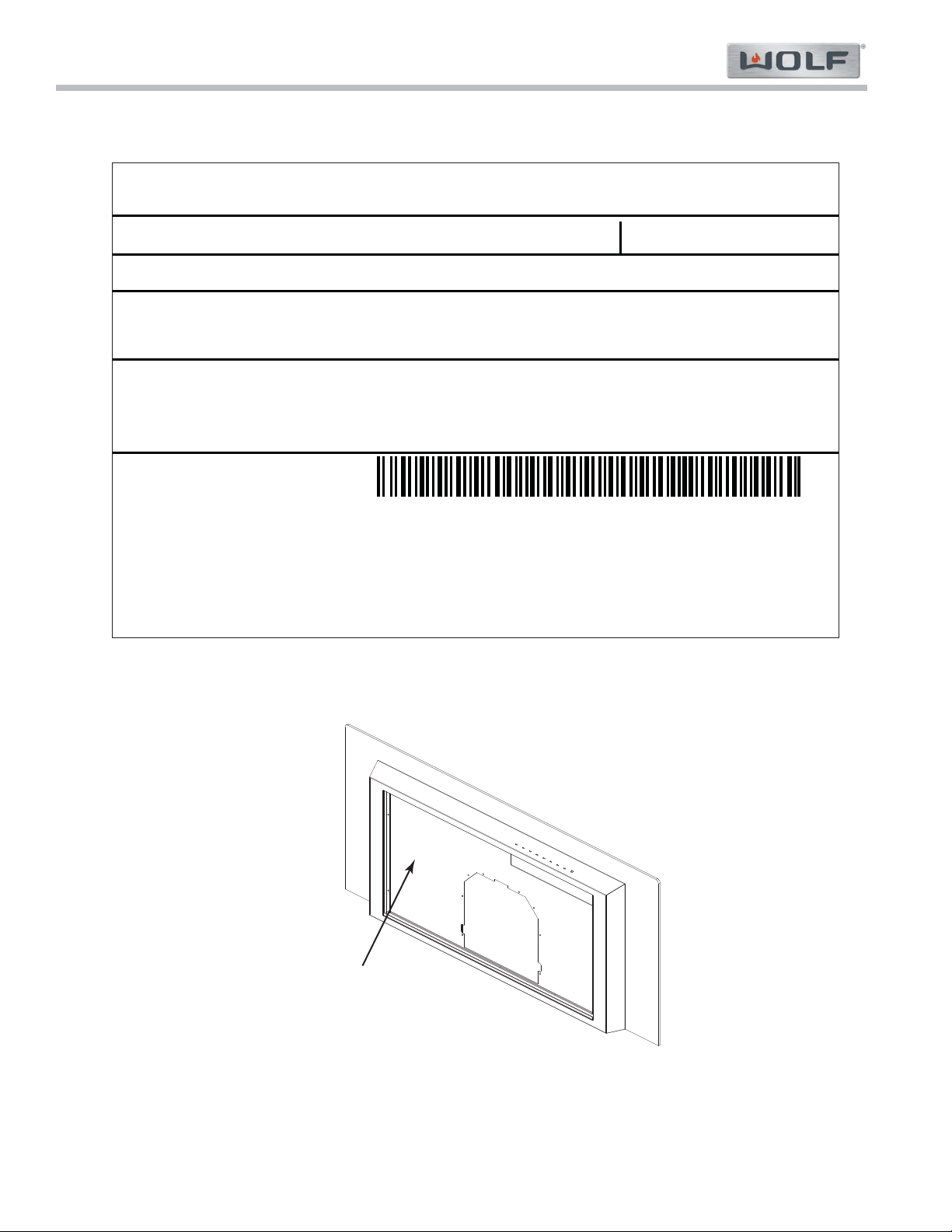
Information Plate and Serial Number
See Figure 1-1 for typical Information Plate layout. •
See Figures 1-2 for Information Plate location. •
WARRANTY INFORMATION
Page 4
V-Series Cooktop Hoods
V-Series Cooktop Hoods
General Information
1-5
#825309 - Revision A - August, 2014
MODEL: VW36S
5610315
120 Vac 60 Hz 2x1 W LED LAMPS
THERMALLY PROTECTED
FB Serial: 15508176 403
Serial: 15508176
TO PROTECT FINISH, WASH WITH MILD SOAP OR DETERGENT ONLY.TO PROTECT FINISH, WASH WITH MILD SOAP OR DETERGENT ONLY.
COMBINED RATING:
2.6A 300W with BLOWER-VENILATION 600CFM Internal Blower Unit
3.0A Maximum Recommended Remote Blower
110.0298.934
00000295500310278923
Wolf Appliance, Inc
Fitchburg, WI 53719
800-222-7820
991.0298.932
www.wolfappliance.com
Figure 1-2. Information Plate Location
Information Plate
(behind Filters)
Figure 1-1. Information Plate
Page 5

General Information
V-Series Cooktop Hoods
V-Series Cooktop Hoods
1-6
#825309 - Revision A - August, 2014
Model Number Key
Model: ICB V W 36 G
International
Product
Type
Size
Style
Product
V V-Series Hoods
Type
W Wall Hood
I Island Hood
Size
30,” 36,” 42,” and 45.”
Style
G Glass
S Stainless Steal
B Black
Page 6
2-2
#825309 - Revision A - August, 2014
V-Series Cooktop Hoods
V-Series Cooktop Hoods
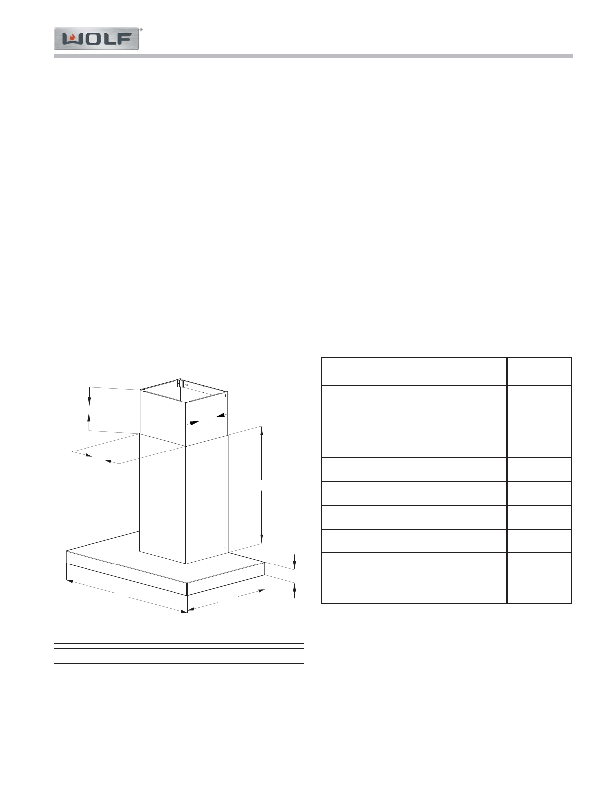
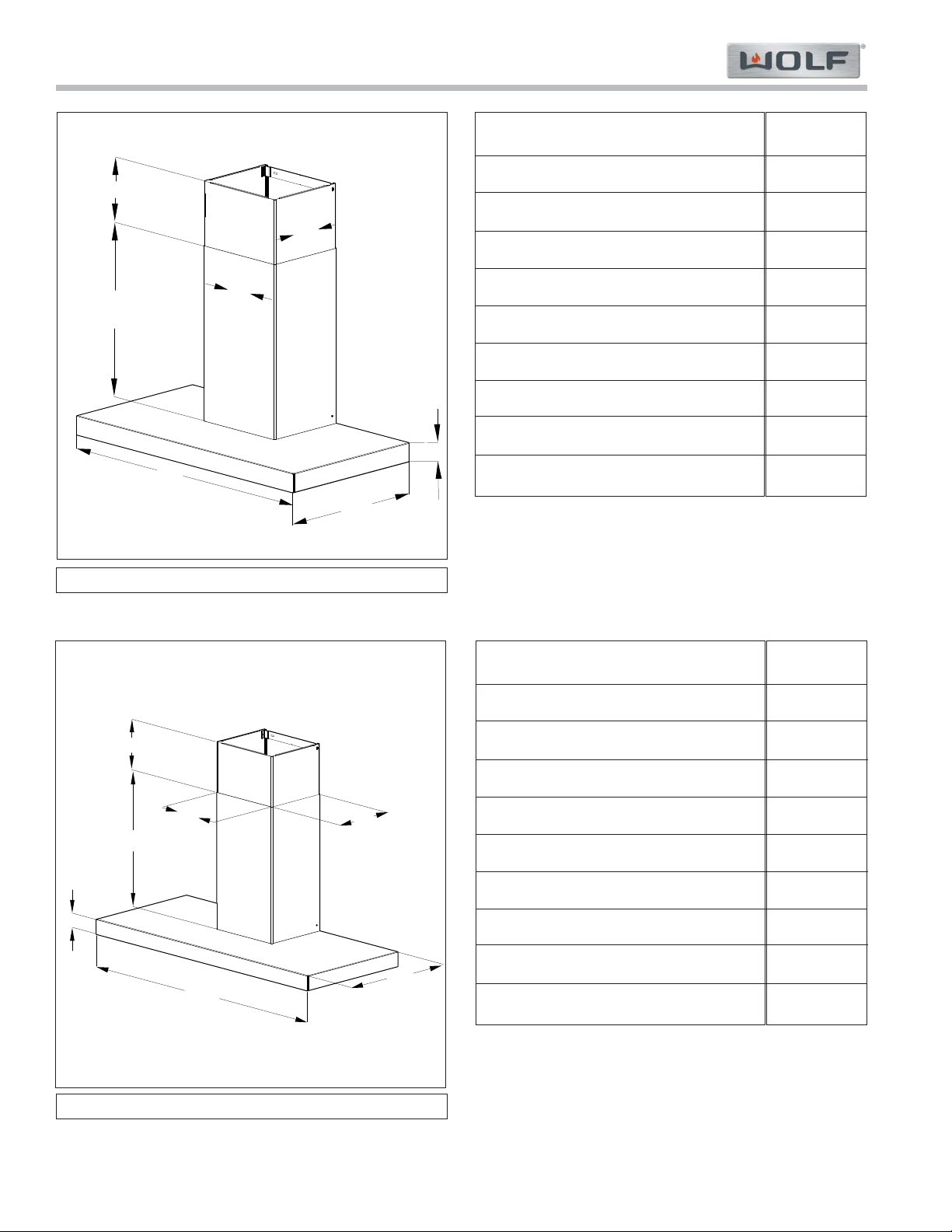
INSTALLATION INFORMATION
This section of the manual covers some of the installation issues that a service technician may need to know
when servicing a Wolf V-Series Cooktop Hood. All dimensions are in inches.
Maximum of three 90 degree elbows.
Hood should not be installed on GFI receptacle.
Hood should be installed on 15 amp dedicated circuit.
Ducting should be 6” ridged ducting and not flexible ducting.
Maximum amp draw of any Blower Motor used is 3.0 amps.
Notes:
For Electrical, Placement, and Ducting Installation Requirements see Page 8.•
It is possible to use 10” ducting but you would have to transition to the 10” ducting after the Support Frame•
on Island Hoods, or after the Easy Cube on Wall Hoods.
10.25”10.25”
2.25”2.25”
19.25”19.25”
30.00”30.00”
11.75”11.75”
21.25”21.25”
7.88” to 18.00”7.88” to 18.00”
VW30B
VW30B
Overall Width
Hood Height (excluding chimney)
Minimum Height (chimney contracted)
Maximum Height (chimney extended)
Overall Depth
Internal Blower(s)
Inline Blower(s)
Remote Blower(s)
Duct Size
30”
2.25”
31.38”
41.5”
19.25”
300, 600 cfm
600 cfm
600 cfm
6”
Dimensions may vary +/- 1/8”
Page 7
2-3
#825309 - Revision A - August, 2014
V-Series Cooktop Hoods
V-Series Cooktop Hoods
10.25”10.25”
2.25”2.25”
19.25”19.25”
21.25”21.25”
7.88” to 18.00”7.88” to 18.00”
36.00”36.00”
11.75”11.75”
45.00”45.00”
19.25”19.25”
2.25”2.25”
11.75”11.75”
10.25”10.25”
21.25”21.25”
7.88” to 18.00”7.88” to 18.00”
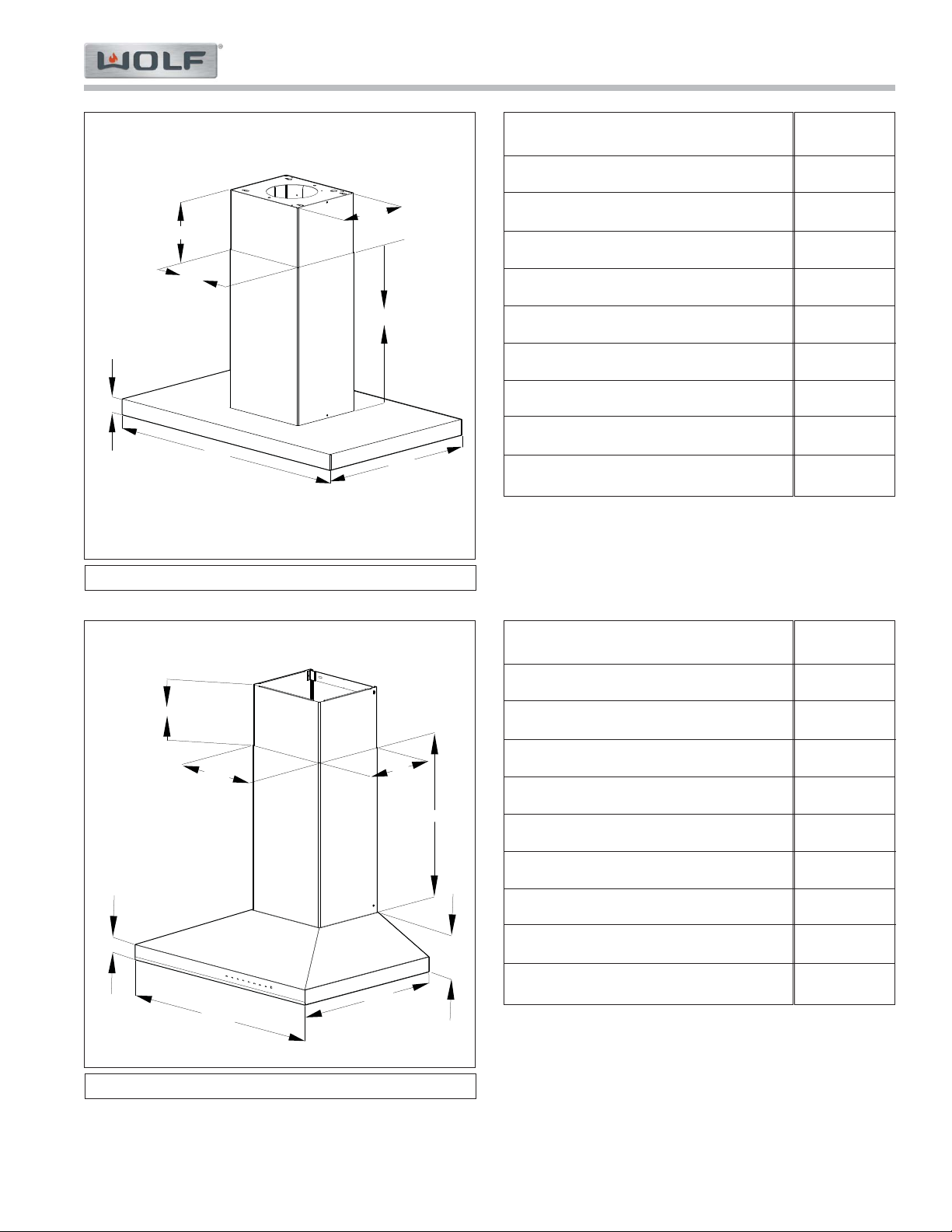
VW36B
VW45B
VW36B
Overall Width
Overall Height (excluding chimney)
Minimum Height (chimney contracted)
Maximum Height (chimney extended)
Overall Depth
Internal Blower(s)
Inline Blower(s)
Remote Blower(s)
Duct Size
36”
2.25”
31.38”
41.5”
19.25”
300, 600 cfm
600 cfm
600 cfm
6”
VW45B
Overall Width
Overall Height (excluding chimney)
Minimum Height (chimney contracted)
Maximum Height (chimney extended)
Overall Depth
Internal Blower(s)
Inline Blower(s)
Remote Blower(s)
Duct Size
45”
2.25”
31.38”
41.5
19.25”
300, 600 cfm
600 cfm
600 cfm
6”
Dimensions may vary +/- 1/8”
Page 8
2-4
#825309 - Revision A - August, 2014
V-Series Cooktop Hoods
V-Series Cooktop Hoods
2.25”2.25”
42.00”42.00”
26.25”26.25”
11.25”11.25”
13.75”13.75”
23.63”23.63”
0.0” to 8.37”0.0” to 8.37”
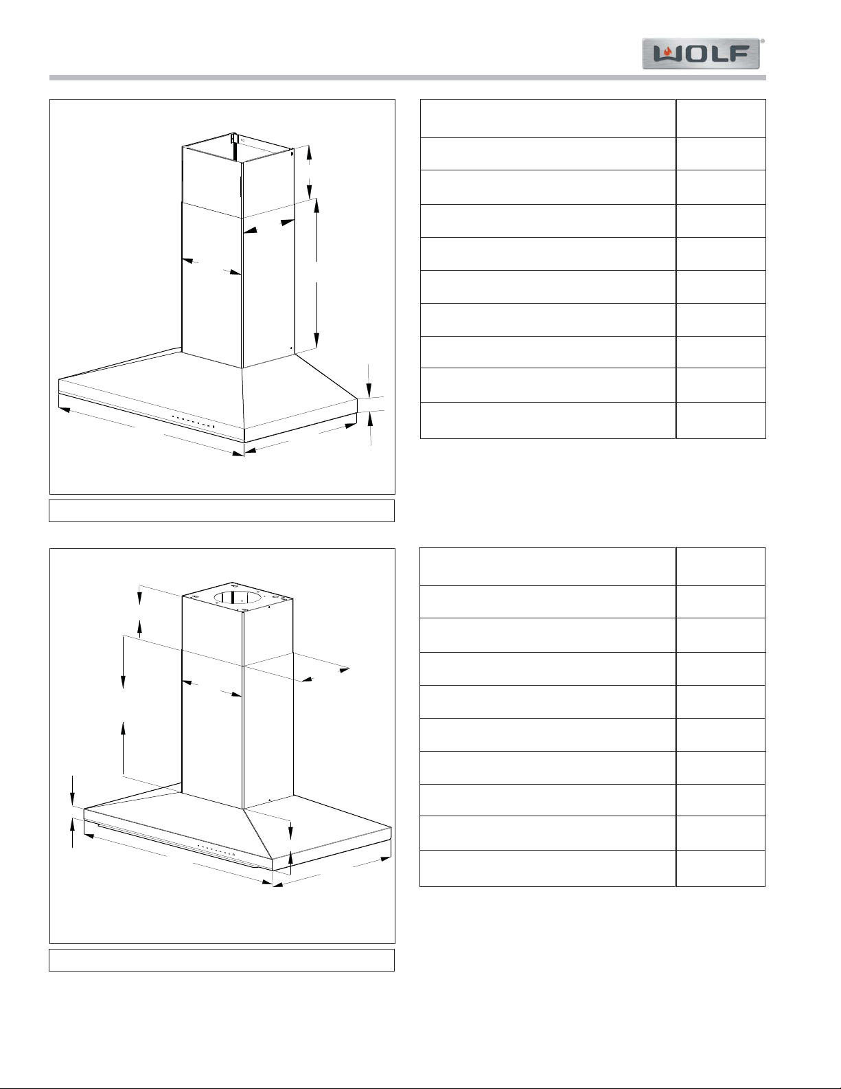
VI42B
10.25”10.25”
11.75”11.75”
22.00”22.00”
30.00”30.00”
2.00”2.00”
21.25”21.25”
7.50” to 18.13”7.50” to 18.13”
6.00”6.00”
VW30S
VI42B
Overall Width
Overall Height (excluding chimney)
Minimum Height (chimney contracted)
Maximum Height (chimney extended)
Overall Depth
Internal Blower(s)
Inline Blower(s)
Remote Blower(s)
Duct Size
42”
2.25”
25.5”
34.25”
26.25”
300, 600 cfm
600 cfm
600 cfm
6”
VW30S
Overall Width
Overall Height (excluding chimney)
Minimum Height (chimney contracted)
Maximum Height (chimney extended)
Overall Depth
Internal Blower(s)
Inline Blower(s)
Remote Blower(s)
Duct Size
30”
6.00”
34.75”
45.38
22”
300, 600 cfm
600 cfm
600, 1200 cfm
6”
Dimensions may vary +/- 1/8”
Page 9
2-5
#825309 - Revision A - August, 2014
V-Series Cooktop Hoods
V-Series Cooktop Hoods
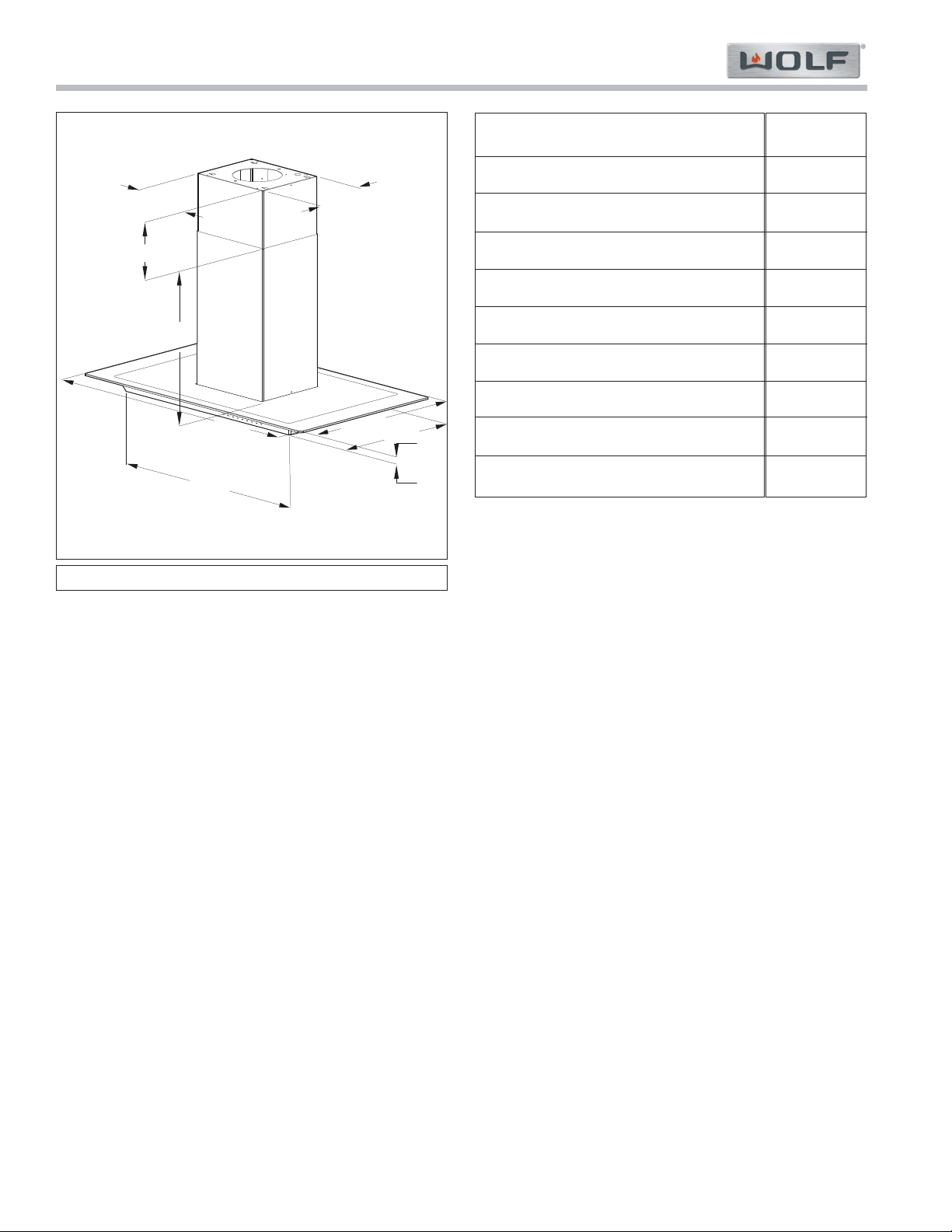
36.00”36.00”
2.00”2.00”
21.25”21.25”
7.50” to 18.13”7.50” to 18.13”
11.75”11.75”
10.25”10.25”
22.00”22.00”
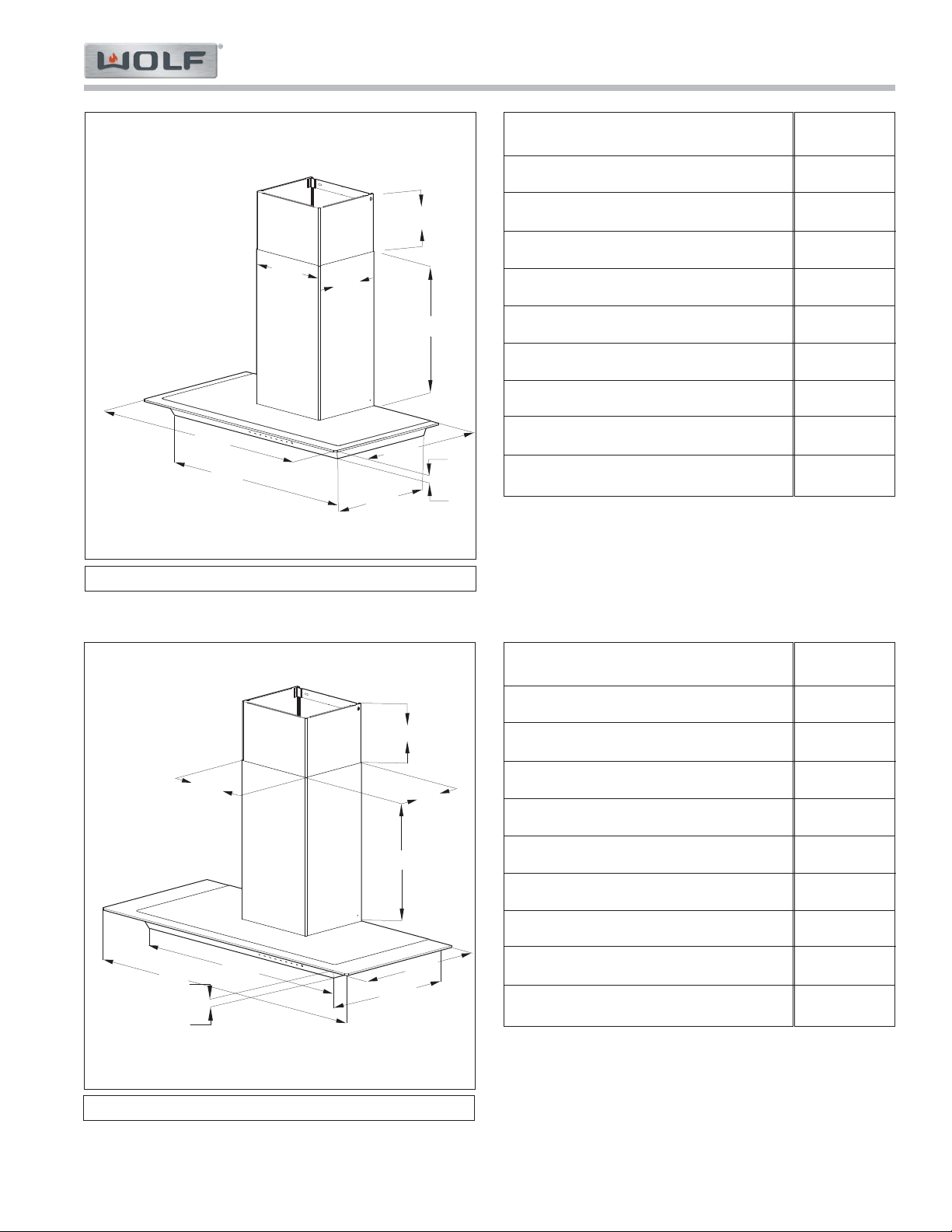
VW36S
42.00”42.00”
26.50”26.50”
2.00”2.00”
13.75”13.75”
11.25”11.25”
0.00” to 7.87”0.00” to 7.87”
23.63”23.63”
6.00”6.00”
VI42S
VW36S
Overall Width
Overall Height (excluding chimney)
Minimum Height (chimney contracted)
Maximum Height (chimney extended)
Overall Depth
Internal Blower(s)
Inline Blower(s)
Remote Blower(s)
Duct Size
36”
6.0”
34.75”
45.38
22”
300, 600 cfm
600 cfm
600, 1200 cfm
6”
VI42S
Overall Width
Overall Height (excluding chimney)
Minimum Height (chimney contracted)
Maximum Height (chimney extended)
Overall Depth
Internal Blower(s)
Inline Blower(s)
Remote Blower(s)
Duct Size
42”
6.0”
29.63”
37.5”
26.25”
300, 600 cfm
600 cfm
600, 1200 cfm
6”
Dimensions may vary +/- 1/8”
Page 10
2-6
#825309 - Revision A - August, 2014
V-Series Cooktop Hoods
V-Series Cooktop Hoods
19.25”19.25”
45.00”45.00”
34.00”34.00”
21.25”21.25”
7.88” to 18.00”7.88” to 18.00”
11.75”11.75”
10.25”10.25”
16.00”16.00”
2.25”2.25”
VW45G
30.50”30.50”
36.00”36.00”
16.00”16.00”
19.25”19.25”
11.75”11.75”
21.25”21.25”
10.25”10.25”
7.88” to 18.00”7.88” to 18.00”
2.25”2.25”
VW36G
VW36G
Overall Width
Overall Height (excluding chimney)
Minimum Height (chimney contracted)
Maximum Height (chimney extended)
Overall Depth
Internal Blower(s)
Inline Blower(s)
External Blower(s)
Duct Size
36”
2.25”
31.38”
41.50”
19.25”
300, 600 cfm
600 cfm
600 cfm
6”
VW45G
Overall Width
Overall Height (excluding chimney)
Minimum Height (chimney contracted)
Maximum Height (chimney extended)
Overall Depth
Internal Blower(s)
Inline Blower(s)
External Blower(s)
Duct Size
45”
2.25”
31.38”
41.50”
19.25”
300, 600 cfm
600 cfm
600 cfm
6”
Dimensions may vary +/- 1/8”
Page 11
2-7
#825309 - Revision A - August, 2014
V-Series Cooktop Hoods
V-Series Cooktop Hoods
13.75”13.75”
11.25”11.25”
26.25”26.25”
45.00”45.00”
34.00”34.00”
20.00”20.00”
23.63”23.63”
2.25”2.25”
0.00” to 8.37”0.00” to 8.37”
VI45G
VI45G
Overall Width
Overall Height (excluding chimney)
Minimum Height (chimney contracted)
Maximum Height (chimney extended)
Overall Depth
Internal Blower(s)
Inline Blower(s)
External Blower(s)
Duct Size
45”
2.25”
25.5”
34.25
26.25”
300, 600 cfm
600 cfm
600 cfm
6”
Dimensions may vary +/- 1/8”
Page 12

2-8
#825309 - Revision A - August, 2014
V-Series Cooktop Hoods
V-Series Cooktop Hoods
Installation Requirements
Hood Placement:
Both the Island Hood and Wall Hood should be
installed so that the bottom of the hood is 30” to 36”
above countertop. (See Figure 1)
Hood
Countertop
30” to 36”
Figure 1. Countertop to Hood Placement
Electrical:
Installation must be electrically grounded in accordance with local codes or, in the absence of local
codes, with National Electrical Code, ANSI/NFPA70.
Electrical supply for Wall Hoods and Island Hoods
should be located in shaded area in Figure 2.
From where Electrical Supply wires enter the hood
area:
Allow a minimum of 12” (inches) wire for connection to
Wall Hood junction box.
Allow a minimum of 6’ (feet) of wire for connection to
Island Hood junction box.
A separate circuit, servicing only this appliance is
required.
Notes:
Required Electrical Supply: Grounded, 110/120•
VAC, 60 Hz, 15 amp dedicated circuit.
No GFI Circuit.•
18”
E
Figure 2. Electrical Supply Area
Installing hood at less then 30” can damage hood•
Touch Control, LED Assemblies, or wiring.
Placing hood above 36” will reduce efficiency of•
the hood’s performance.
Page 13

2-9
#825309 - Revision A - August, 2014
V-Series Cooktop Hoods
V-Series Cooktop Hoods
Installation Requirements
Ducting:
6” (inch) round, rigid metal duct is recommended for
V- Series cooktop ventilation.
Wall Hoods and Island Hoods include a Backdraft
Damper. Local codes may require use of addition
backdraft damper or make up air.
A straight, short run is most effective and will improve
performance and reduce noise. Elbows, transitions,
and air boxes all reduce performance of hood.
Reducing the duct size less then 6” (inches) for even
a short span reduces air flow for the entire duct run.
Duct run should not exceed 50 feet Equivalent
Ducting Length. (See Figure 3).
Internal and In-Line blowers require a Roof or Wall
Cap the same duct size as duct run. (See Figure 4).
Contact your local HVAC professional for specific
codes and requirements.
1’ of 6” Ducting = 4’ of
Equivalent Ducting Length
6” Roof/Wall Cap with Damper
is 30’ of Equivalent Ducting Length
6” 90 degree Elbow = 24’
of Equivalent Ducting Length
Figure 3. Equivalent Duct Feet
Ductwork Installation
Through the roof
Ductwork Installation
Through the eave
Ductwork Installation
Through the wall
6” Wall Cap
6” Roof Cap
6” Elbow
6” Duct
6” Duct
Eave Vent
Figure 4. Duct Run Examples
Page 14

2-10
#825309 - Revision A - August, 2014
V-Series Cooktop Hoods
V-Series Cooktop Hoods
Wall Hood Mounting
If an Internal Blower is being installed, install Internal
Blower prior to mounting the Hood.
1. Mark center line of hood installation. Using the
information in Figure 5 and the Chart below, mark
hole locations for mounting brackets. Additional
wall framing is recommended in this area.
a. Position two mounting brackets for chimney
flue, then install using two mounting screws
per bracket.
b. Install the Easy Cube mounting screws so
there is approximately 1/4” gap between the
screw head and wall.
Note: If wall framing is not available, use of wall
anchors is recommended.
9
1
/8
"
(232)
A
(433)
(19)
17
1
/16
"
3
/4
"
BOTTOM OF HOOD
CEILING
B
Figure 5. Bracket Mounting Location
Hood
Black
Glass
Stainless
Dimension “A”
12-3/4”
12-9/16”
16-3/8”
Dimension “B”
31-3/8” to 41-1/2”
31-3/8” to 41-1/2”
34-3/4” to 45-3/8”
MountingMounting
TabTab
LevelingLeveling
ScrewScrew
Figure 6. Easy Cube Mounting.
2. Place the mounting tabs of the Easy Cube over the
mounting screws. Use leveling adjustment screws
to ensure hood is level. (See Figure 6)
3. Install Upper Chimney to Chimney Bracket.
4. Place Lower Chimney over Upper Chimney and
rest the Lower Chimney on the Hood Body. Fasten
two screw to the Easy Cube.
Page 15

2-11
#825309 - Revision A - August, 2014
V-Series Cooktop Hoods
V-Series Cooktop Hoods
Installation Information
Island Hood Mounting
Island Hoods have a Support Frame that is adjustable
in height. The Support Frame is attached to ceiling,
the Upper and Lower Chimney is attached, then Hood
Body.
Note: If an Internal Blower is being installed, mount
Hood Body to Easy Cube/Support Frame prior
to installing Internal Blower. The two pin molex
connector for Hood Lights must be connected
prior to Internal Blower being installed.
1. Use template provided with Island Hood to mark
location of electrical supply and mounting holes for
Support Frame. Actual Template has a 6” diameter
circle for ducting. (See Figure 7)
a. Use 1-1/4” drill to create a hole for electrical
power supply.
b. Place four mounting screws in ceiling in indi-
cated location. Do not tighten screws.
2. Place Support Frame on mounting screws and
tighten mounting screws.
3. Adjust height of Support Frame by loosening four
screws on each arm of Support Frame. This
adjustment can be made prior to mounting Support
Frame if desired. (See Figure 8)
8
5/8”
(219)
Electrical
Location
11"
(279)
Figure 7. Template Example
Support
Arm
Screws
Figure 8. Support Frame
4. Install Damper on top of Easy Cube. Install
Ducting. Connect electrical supply to junction
box. Connect remote/inline blower in electrical
box.
5. Install Upper Chimney.
6. Install Lower Chimney.
7. Install Hood Body to Support Frame.
8. Install Internal Blower.
Page 16

3-2
#825309 - Revision A - August, 2014
V-Series Cooktop Hood
V-Series Cooktop Hood
Component Access
COMPONENT ACCESS AND REMOVAL
This section explains how to access and remove components from a Wolf V-Series Hood.
An attempt has been made to arrange these procedures in such a way as to simulate which components would
need to be removed first in order to gain access to the other components. When following a component removal
procedure, it may be necessary to reference another component removal procedure listed earlier in this section.
Note: Before continuing, please take note of the WARNINGS and CAUTIONS below.
• When working on the Hood and components, be careful when handling sheet metal parts. There may be sharp
edges present.
• Chimney should only be secured at the locations provided for by the Hood. Do Not cement, grout, or silicone the
chimney in any manner. Warranty does not cover removing or reinstalling chimneys attached in this manner.
• TO AVOID ELECTRIC SHOCK. POWER TO HOOD MUST BE DISCONNECTED WHEN EVER SERVICING
AND/OR ACCESSING COMPONENTS AND/OR REMOVING COMPONENTS POWERED BY ELECTRICITY OR
COMPONENTS NEAR OTHER ELECTRICAL COMPONENTS.
• IF IT IS NECESSARY TO REMOVE A HOOD FROM ITS INSTALLATION REMEMBER THAT THE UNITS ARE
HEAVY AND MUST BE LOWERED FROM THE INSTALLATION. MAY REQUIRE TWO MEN.
• REMOVING A UNIT FROM ITS INSTALLATION SHOULD ONLY BE PERFORMED BY AN AUTHORIZED SERVICE TECHNICIAN OR INSTALLER.
Page 17

3-3
#825309 - Revision A - August 2014
Component Access
V-Series Cooktop Hood
V-Series Cooktop Hood
Figure 3-1. Filter Cover Hinge
Filter Covers - Black Hoods
Black hoods have a Filter Cover. Filter Cover has a pin
that snaps into a receptacle on hood side. Pull on Filter
Cover to open. Press Filter Cover in to close.
To Remove Filter Cover:
1. Open Filter cover to 90 degrees. Press Hinge
Release Pin toward center of hood. Disengage
Filter Cover from the hinge. (See Figure 3-1)
2. Slide Filter Cover to right and disengage pin from
other hinge.
Hinge Release
Pin
Push
Figure 3-2. Filter Removal
Filter
Filter
Bottom of Hood
Filters
All V-Series Hoods have aluminum mesh filters. Glass
and Stainless Steel models are same filter. All filters
are removed in the same manner.
To Remove Filter:
1. Push plastic tab on front end of Filter toward rear of
Hood and gentlely pull down. (See Figure 3-2)
2. Pull Filter forward and remove.
Page 18

3-4
#825309 - Revision A - August, 2014
V-Series Cooktop Hood
V-Series Cooktop Hood
Component Access
Figure 3-5. Internal Blower in Easy Cube
Figure 3-4. LED Light Assembly
Figure 3-3. Light Assembly Support Removal
LED Light Assembly
Hood lights are LED fixtures that must be replaced as
assemblies. Lights are 12 VDC.
To Remove LED Light Assembly:
1. Extract screws holding Light Assembly Support to
hood. Lower front part of Light Assembly Support
and pull toward center of hood. (See Figure 3-3)
2. Align spring clips to square notches in Light
Assembly Support. Depress spring clips on side of
LED Light Assembly and push through Light
Assembly Support. (See Figure 3-4)
Square
Notches
Spring Clips
Spring Clips
Square
Notches
Internal Blower Removal
The 600 cfm Internal Blower is mounted in Easy Cube
portion of hood. Once Filter Covers (Black Hoods) and
Filters are removed Internal Blower can be extracted.
To Remove Internal Blower:
1. Support Internal Blower and extract two screws at
bottom of mounting plate. (See Figure 3-5)
2. Lower Internal Blower from hood. Disconnect
Internal Blower Harness from Internal Blower.
Touch Control
Screw
Touch Control
Screw
Ribbon Cable
Screws
Internal Blower
Connector
Blower Mounting
Screws
Touch Control Board
The touch control board is removed differently for black
h
oods and stainless steel/glass hoods. Once the light
assembly support is removed, the touch control
assembly case, which contains the board, is accessible.
Remove the Touch Control Board - Black Hoods:
1. Open the case.
2. Remove the two ribbon c
disconnect the ribbon cable.
3. Remove the two touch control board screws, and
remove the touch control board.
able screws, and
Figure 3-6. Black Hood Touch Control Board
Page 19

3-5
#825309 - Revision A - August 2014
Component Access
V-Series Cooktop Hood
V-Series Cooktop Hood
Easy Cube Access
The Easy Cube is located directly above the hood body.
If their is an Internal Blower it is located inside the Easy
Cube. The Power Board Assembly, Light Transformer,
and Hood Electricals are mounted on top of the Easy
Cube.
To Access Area Above Easy Cube:
Note: The Lower Chimney should not be secured to
the wall in any manner. In instances where the
Lower Chimney has been secured, it is the customer’s responsibility to have the Lower
Chimney removed.
1. Extract two screws at bottom of Lower Chimney.
Raise and block Lower Chimney up on Island
Hoods, and remove Lower Chimney on Wall Hoods.
2. The Easy Cube has the control board mounted on
front edge, and unit electricals mounted on back
edge. (See Figure 3-7)
Touch Control Assembly - continued
To Remove Touch Control Assembly - Glass and
Stainless Steel Hoods:
1. Extract two Ribbon Cable screws and disconnect
Ribbon Cable. (See Figure 3-6)
2. Release six tabs retaining Touch Control Assembly
to Hood.
Figure 3-8. Power Board Assembly
Figure 3-7. Wall Hood Easy Cube - Side View
Power Board
Assembly
Unit Electrical
Box
Screws to
Easy Cube
Case Screws
Case Screws
Ribbon Cable
Cover
Power Board Assembly Removal
The Power Board Assembly is located in a black case
attached by two screws to front of Easy Cube.
To Remove Power Board Assembly:
1. Open Ribbon Cable cover with a flat blade screwdriver and disconnect Ribbon Cable.
(See Figure 3-8)
2. Extract two screws holding Power Board Assembly
case to Easy Cube.
3. Extract four screws holding Power Board Assembly
case together.
4. Disconnect harnesses from Power Board Assembly.
5. Remove three black screws holding Power Board to
Power Board Assembly case.
(See Figure 3-9 - Red Circles)
Primary
Power
12 VDC to
Lighting
12 VDC to
Touch Control
Figure 3-9. Power Board and Transformer
Transformer:
Transformer is located in top cover of Power Board
Assembly case. It is held in with two screws. Orange
wires are 120 VAC to Primary side of Transformer.
Harness in wire sheath is 12 VDC to hood lights.
Connector with gray, black, and white wires is 12 VDC
to Touch Control.
Page 20

V-Series Cooktop Hoods
V-Series Cooktop Hoods
Troubleshooting
4-2
#825309 - Revision A - August, 2014
TROUBLESHOOTING
This section explains how to troubleshoot various components in Wolf V-Series Cooktop Hood.
An attempt has been made to arrange these procedures in such a way as to trace the issue from component to
component.
Note: Before continuing, please take note of the WARNINGS and CAUTIONS below.
• TO AVOID ELECTRIC SHOCK. POWER TO HOOD MUST BE DISCONNECTED WHEN PREPARING FOR A
SPECIFIC TEST. CARE SHOULD BE USED WHILE PERFORMING ANY TEST WITH THE HOOD ENERGIZED.
• IF IT IS NECESSARY TO REMOVE A HOOD FROM ITS INSTALLATION REMEMBER THAT THE UNITS ARE
HEAVY AND MUST BE LOWERED FROM THE INSTALLATION.
• When working on the Hood and components, be careful when handling sheet metal parts. There may be
sharp edges present.
Page 21

Troubleshooting
V-Series Cooktop Hoods
V-Series Cooktop Hoods
4-3
#825309 - Revision A - August, 2014
Troubleshooting and Test Procedures
Troubleshooting table ............................................... 4-3
1. Hood Lights and Blower do not energize ............. 4-3
2. Blower Motor Runs only at High Speed ............... 4-4
3. Hood Lights do not work ....................................... 4-4
4. Blower Motor does not run at any speed ............. 4-5
a. Checks for Internal Blowers ............................ 4-5
b. Checks for External/Inline Blowers
................ 4-6
5. Blower Motor runs but not at all four speeds ... 4-6
6. Hood does not move enough Air ...................... 4-6
DIAGNOSTIC TEST RESOLUTION MANUAL PAGE
Check Voltage at Power
Cable to Easy Cube:
L1 to Ground = 115 VAC
N to Ground = 0 VAC
L1 to N = 115 VAC
Replace or repair Power
Cable.
Test Procedure #2.
Check Voltage at three
pin connector in Easy
Cube Electrical Box.
Pin 1 to Pin 2 =115 VAC
Pin 2 to Pin 3 =0 VAC
Pin 1 to Pin 3 =115 VAC
Replace/Repair
Electrical Connector or
wires.
Test Procedure #3.
Check Voltage at Power
Board:
Pin 1 to Pin 2 =115 VAC
Replace/Repair connector from Electrical Box
on Easy Cube to Power
Board.
Section 3, Page 5.
Test Procedure #4.
SYMPTOM
Hood Lights and Blower
do not energize. No GFI
Circuit.
Check house circuit is
115 VAC, 15 amp, dedicated circuit.
Breaker is closed.
Bring circuit into specification.
Close Breaker.
Installation Guide.
Service Manual Section
2.
Check Voltage at J-Box:
L1 to Ground = 115 VAC
N to Ground = O VAC
L1 to N = 115 VAC
Correct circuit.
Correct Polarity.
Correct Ground.
Assure connections are
tight.
Installation Guide.
Test Procedure #1.
Test Procedures
Test Procedures ......................................................... 4-7
1. Testing Line Voltage at J-Box ............................... 4-7
2. Testing Line Voltage at Power Cable .................... 4-7
3. Testing Line Voltage at 3 Pin Connector inside
Electrical Box ....................................................... 4-7
4. Testing Line voltage at 7 Pin Connector on Power
Board .................................................................... 4-7
5. Testing Line Voltage to Transformer and Blower
Motor ..................................................................... 4-8
6. Testing Line Voltage to Transformer on Power
Board ................................................................... 4-8
7. Testing 12 VDC at Transformer Secondary........... 4-8
8. Testing Lighting Voltage at Easy Cube ................. 4-8
9. Testing Lighting Voltage at Light Support ............. 4-9
10. Testing LED Assembly for a Short ........................ 4-9
11. Testing Blower Voltage at Easy Cube
Connection ............................................................ 4-9
12. Testing Blower voltage at Blower Connection ...... 4-9
13. Testing Internal Blower for Open or Short ............ 4-9
14. Testing External/Internal Blower for Open
or Short ................................................................. 4-9
Page 22

V-Series Cooktop Hoods
V-Series Cooktop Hoods
Troubleshooting
4-4
#825309 - Revision A - August, 2014
SYMPTOM
Hood Lights and Blower do
not energize - continued.
Blower motor runs only at
High Speed.
Power Board fault. Replace Power Board. Section 3, Page 5.
Hood Lights do not work.
DIAGNOSTIC TEST
RESOLUTION MANUAL PAGE
If one LED is out in the
LED Light Assembly.
Replace LED Light
Assembly.
Section 3, Page 4.
With Blower and Lights
energized:
Check 115 VAC L to N
on connector (orange) to
Transformer.
Check 115 VAC Blue to
Brown on terminal block
in Electrical Box on Easy
Cube.
With power Off check
that ribbon cable from
Power Board to Touch
Control is seated correctly:
Ribbon Cable connector
on Power Board.
Locking connector in
Easy Cube.
Connector on Touch
Pad.
If Ribbon Cable is seated correctly at all points,
and no voltage out of
Power Board then the
Power Board or Touch
Control is bad. Try
replacing the Power
Board first.
Section 3, Page 4.
Section 3, Page 5.
Test Procedure #5.
Remove connector from
Secondary side of
Transformer and check
for 12 VDC between
pins on Transformer.
If no voltage replace the
Transformer.
Section 3, Page 5.
Test Procedure #7.
Unplug two pin connector in Easy Cube and
check for 12 VDC.
Note: Internal Blower
may need to be
removed.
Replace harness from
Easy Cube to
Transformer.
Section 3, Page 5.
Test Procedure #8.
Unplug two pin connector behind Light Support
and check for 12 VDC
Replace harness from
Easy Cube to Hood
Body.
Section 3, Page 4.
Test Procedure #9.
Ohm LED Light
Assembly connector.
Assure there is no short.
Replace LED Light
Assemblies.
Section 3, Page 4.
Test Procedure #10.
Page 23

Troubleshooting
V-Series Cooktop Hoods
V-Series Cooktop Hoods
4-5
#825309 - Revision A - August, 2014
Remove connector
LUX1 from Power Board
and check for 115 VAC
from Pin 1 to Pin 2.
If Blower Motor is working, replace Power
Board.
Section 3, Page 4.
Test Procedure #6.
On motor Side of connector Ohm out:
Pin 4 to Pin 5.
Pin 4 to motor case.
Pin 5 to motor case.
If reading Open Pin 4 to
Pin 5, or Continuity Pin
4 or Pin 5 to motor case,
confirm it is not Blower
Motor Harness, then
replace Blower Motor.
Section 3, Page 4.
Test Procedure #13.
Remove connector from
Primary side of
Transformer and check
for 115 VAC between
Orange wires.
Replace/Repair harness
from Power Board to
Transformer.
Section 3, Page 5.
Test Procedure #5.
SYMPTOM
DIAGNOSTIC TEST
RESOLUTION MANUAL PAGE
Hood Lights do not work continued.
Check Voltage at Power
Cable to Easy Cube:
L1 to Ground = 115 VAC
N to Ground = 0 VAC
L1 to N = 115 VAC
Replace/Repair
Electrical Connector or
wires
Installation Guide.
Test Procedure #2.
Blower Motor does not run
at any speed.
Note: Perform Checks for
Internal Blower Motor or
Checks for External/Inline
Blower Motor Prior to these
checks.
Check Voltage at J-Box:
L1 to Ground = 115 VAC
N to Ground = O VAC
L1 to N = 115 VAC
If Lights are working,
likely this is a short or
loose connection.
Installation Guide.
Test Procedure #1.
Check for 115 VAC at
terminal block in
Electrical Box on Easy
Cube.
Replace/Repair connector from Power Board to
Electrical Box.
Test Procedure #5b.
Unplug three pin connector and check for 115
VAC Pin 1 to Pin 3
inside Easy Cube.
Disconnect Internal
Blower connector from
Blower, check for 115
VAC Pin 4 to Pin 5 on
Hood side of connector.
Replace harness from
terminal block to Easy
Cube Connector.
Replace Blower Motor
Harness.
Test Procedure #11.
Section 3, Page 4.
Test Procedure #12.
Check Voltage at three
pin connector in Easy
Cube Electrical Box.
Pin 1 to Pin 2 =115 VAC
Pin 2 to Pin 3 =0 VAC
Pin 1 to Pin 3 =115 VAC
Replace/Repair
Electrical Connector or
wires.
Test Procedure #3.
Check Voltage at Power
Board:
Pin 1 to Pin 2 =115 VAC
Replace/Repair connector from Electrical Box
on Easy Cube to Power
Board.
Section 3, Page 5.
Test Procedure #4.
Checks for Internal Blower
Motor.
Notes:
Perform “Blower Motor does
not run at any speed”
checks after these checks if
needed.
Internal Blower will need to
be removed.
Page 24

V-Series Cooktop Hoods
V-Series Cooktop Hoods
Troubleshooting
4-6
#825309 - Revision A - August, 2014
This failure can be
caused by failure of the
Triac on the Power
Board or by a Touch
Control Failure. At this
time there is no test to
determine where the failure is.
Replace Power Board or
Touch Control.
Section 3, Page 4
Section 3, Page 5
On motor side of terminal block disconnect
External/Inline Blower
Motor wires:
Ohm out between wires.
Ohm each wire to
ground.
If reading Open between
Blower wires, or
Continuity from either
Blower Wire to Ground:
Check that the wiring
between terminal block
and Blower Motor is
good. If wiring is good,
replace External/Inline
Blower.
Installation Guide.
Test Procedure 14.
Check for External/Inline
Blower Motor.
Note: Perform “Blower
Motor does not run at any
speed” checks after these
checks if needed.
Blower Motor runs, but not
at all four Speeds.
Hood does not move
enough Air.
Correct ducting installed.
Verify the duct run is the
correct size including:
Wall/Roof Cap is correct.
No reduction is size at
any point.
Damper is installed correctly.
No excessive elbows.
No excessive length.
No air box used.
Correct Duct issue. Installation Guide.
Service Manual Section
Two.
Blower Motor is not
changing speeds.
On Internal Blowers
remove ducting above
Easy Cube.
On Inline blowers
remove ducting on inlet
and outlet.
On External Blowers
Remove inlet ducting.
Note: With ducting
attached a possible
restriction will prevent
hearing the speed
change.
If no speed change
noticed see “Blower
Motor runs, but not at
all four speeds.”
If there is a speed
change review ducting
again for restriction.
Installation Guide.
Service Manual Section
Two.
Filters are Dirty. Remove Filters to test,
then clean Filters.
Use and Care.
Insufficient Make Up Air Open outside door or
window to test.
Contact HVAC company.
Page 25

Troubleshooting
V-Series Cooktop Hoods
V-Series Cooktop Hoods
4-7
#825309 - Revision A - August, 2014
Test Procedures
1. Testing Line Voltage at J-Box.
J-Box is mounted to the Support Frame on Island
Hoods and is mounted by Installer on wall behind
Upper Chimney on Wall Hoods. (See Figure 4-1)
a. Disconnect wires between Electrical Supply and
Hood.
b. Measure voltage from Electrical Supply L1 (typi-
cally Black) to Ground. Voltage should be 115
VAC.
c. Measure voltage from Electrical Supply Neutral
(typically white) to ground. Voltage should be 0
VAC.
d. Measure voltage from Electrical Supply L1 to
Neutral. Voltage should be 115 VAC.
e. Confirm both ground screw connections are
tight.
Neutral (White)
Ground (Green)
Power Cable
L1 (Black)
3. Testing Line Voltage at 3 Pin Connector in
Electrical Box - continued
Disconnect 3 Pin Connector and test on Power
Cable Receptacle side of connector.
(See Figure 4-2)
a. Measure voltage from Pin 1 to Pin 2. Voltage
should be 115 VAC.
b. Measure voltage from Pin 2 to Pin 3. Voltage
should be 0 VAC.
c. Measure voltage from Pin 1 to Pin 3. Voltage
should be 115 VAC.
2. Testing Line Voltage at the Power Cable.
Power Cable plugs into the top of the Electrical Box
on Easy Cube. (See Figure 4-1)
a. Inside Power Cable measure voltage from L1 to
Ground. Voltage should be 115 VAC.
b. Inside Power Cable measure voltage from
Neutral to Ground. Voltage should be 0 VAC.
c. Inside Power Cable measure voltage from L1 to
Neutral. Voltage should be 115 VAC.
d. Check resistance (ohms) between Ground on
Power Cable and another Ground terminal on a
near by outlet. You should read Continuity.
Figure 4-1. Hood J-Box
3 Pin Connector
Power Cable
Receptacle
Figure 4-2. 3 Pin Connector in Electrical Box
4. Testing Line Voltage at 7 Pin Connector on Power
Board.
On Power Board disconnect 7 Pin Connector from
Power Board. Test on Wire side of connector.
(See Figure 4-3)
a. Measure voltage from Pin 1 to Pin 2. Voltage
should be 115 VAC.
7 Pin Connector
3. Testing Line Voltage at 3 Pin Connector in
Electrical Box.
Inside Electrical Box on top of Easy Cube is a 3 pin
connector that connects the Power Cable receptacle to Power Board connector.
Figure 4-3. 7 Pin Connector in Power Board
Page 26

V-Series Cooktop Hoods
V-Series Cooktop Hoods
Troubleshooting
4-8
#825309 - Revision A - August, 2014
Voltage to
Transformer
Figure 4-4. Light Transformer
Power to Blower
Terminals
Figure 4-5. Terminal Block
8. Testing Lighting Voltage at Easy Cube
a. If Hood has an Internal Blower it will need to be
removed to perform this check.
b. Disconnect two pin Lighting Harness from Easy
Cube connection. (See Figure 4-8).
c. Measure voltage between pins of connector
inside Easy Cube. Voltage should be 12 VDC.
5. Testing Line Voltage to Transformer and Blower
Motor.
Perform both of these tests with the Blower Motor
and Lights Energized.
a. Disconnect two pin connector or screws with
two orange wires to Transformer. Measure volt
age between two pins or wires on Power Board
side of connector. Voltage should be 115 VAC.
(See Figure 4-4)
b. Measure voltage between terminal posts on the
Terminal Block inside Electrical Box. Voltage
should be 115 VAC. (See Figure 4-5)
6. Testing Line Voltage to Transformer on Power
Board.
On Power Board LUX1 is the voltage to
Transformer.
a. Disconnect LUX1 from Power Board and meas-
ure voltage between the pins on the board.
Voltage should be 115 VAC. (See Figure 4-6)
LUX 1
Figure 4-6. LUX1 Connector on Power Board
7. Testing 12 VDC from Transformer Secondary.
Wires in sheath are 12 VDC to LED Assemblies.
The three pin connector is the Lighting Command
Harness. (See Figure 4-7)
a. Disconnect two pin connector from secondary
side of Transformer. Measure voltage on pins
of Transformer. Voltage should be 12 VDC.
b. Disconnect three pin connector from secondary
side of Transformer. Measure voltage between
pins that correspond with black and white wire
on the connector. Voltage should be 12 VDC.
c. Disconnect three pin connector from second-
ary side of Transformer and Power Board.
Check Continuity from each wire in Lighting
Command Harness.
Voltage to
LEDs
Voltage for
Lighting
Commands
Figure 4-7. Transformer Secondary
Light Harness
Connection
Figure 4-8. Lighting Connection in Easy Cube
Page 27

Troubleshooting
V-Series Cooktop Hoods
V-Series Cooktop Hoods
4-9
#825309 - Revision A - August, 2014
9. Testing Lighting Voltage at Light Support
a. Disconnect two pin Lighting Harness from LED
Assembly connection. (See Figure 4-9).
b. Measure voltage between pins of connector on
Easy Cube side of connection. Measure voltage at each Lighting Harness connection.
Voltage should be 12 VDC.
Light Support Assembly
LED Assembly
Connection
LED Assembly
Connection
Light Harness
to Easy Cube
Figure 4-9. Lighting Connection on Light Support
10. Testing LED Assembly for a Short.
a. Disconnect two pin Lighting Harness from LED
Assembly connection. (See Figure 4-9).
b. Measure resistance from each pin of LED
Assembly connector to LED Assembly case.
There should be no Continuity.
Blower Motor
Connection
Figure 4-10. Blower Connection in Easy Cube
11. Testing Blower Voltage Easy Cube Connection.
a. Remove Internal Blower.
b. Disconnect three pin Internal Blower Harness
from Easy Cube connection. (See Figure 4-10)
c. Check for 115 VAC between Pin 1 and Pin 3
inside Easy Cube.
12. Testing Blower Voltage at Blower Connection
a. Disconnect Internal Blower Cable connection
from Internal Blower. (See Figure 4-11).
b. Measure voltage between pins 4 and 5 on the
Easy Cube side of connector.
Internal Blower
Cable Connection
Figure 4-11. Internal Blower Cable Connector
13. Testing Internal Blower for Open or Short
a. Disconnect Internal Blower Cable connection
from Internal Blower. (See Figure 4-12).
b. Measure resistance Pin 4 to Pin 5. If it is open,
replace Blower Motor.
c. Measure resistance Pin 4 to Blower Motor
case, and Pin 5 to Blower Motor case. If there
is Continuity, replace Blower Motor.
Internal Blower
Motor Connection
Figure 4-12. Internal Blower Motor Connection
14. Testing External/Inline Blower for Open or Short
a. Disconnect External/Inline Blower Motor wires
from Terminal Block. (See Figure 4-13).
b. Measure resistance wire to wire.
Measure resistance each wire to ground.
c. If step 14a reads Open or 14b reads Continuity,
then confirm the wiring from the Terminal Block
to the Blower Motor is good. If the wiring is
good, replace the Blower Motor.
Blower Motor
Wires
Figure 4-13. Terminal Block
Page 28

V-Series Cooktop Hoods
V-Series Cooktop Hoods
Technical Data
5-2
#825309 - Revision A - August, 2014
Technical Data
This Technical Data Section has been compiled with the latest information from Faber S.p.A. Company.
600 cfm Internal Blower
414 WATTS
115 VAC
3.6 AMPS
Note: All measurements in Watts, Voltage, or amps are approximate. Actual readings can very plus or minus 10
percent.
General Hood Information:
Light System is 12 VDC.•
Three wire harness from Power Board Assembly to Transformer is Light Control Circuit and is 12 VDC.•
Blower speed is controlled by a Triac on the Power Board Assembly.•
General Use and Care Information:
Delay mode lasts for 10 minutes.•
Activate Boost by holding Hi for 3 seconds. Boost is on for 10 minutes, then returns to prior speed. •
Boost increase air flow by approximately 20%.•
Approximately 100 hour to activate Filter Alarm.•
LED Assembly is S1000 LED Natural White 4000k.•
Remote Control takes 2 AAA batteries.•
Black Hood Use and Care Information:
Hood flashes FC for Recirculation Filter alarm and FG for Mesh Filter alarm. No matter which filter system is•
being used the hood will flash both FC and FG.
Hold Delay for 5 seconds to reset Filter Alarm. Hood will flash FF when reset.•
Hi is displayed for Boost.•
Activate or Deactivate Remote Control by holding On/Off for 5 seconds.•
Hood flashes IR when Remote Control is activated or deactivated.•
Stainless Steel and Glass Hood Use and Care Information:
Hold Filter for 5 seconds to reset Filter Alarm.•
High Blinks when in Boost.•
Activate or Deactivate the Remote Control by holding Delay for 5 seconds with Lights and Blower Motor off.•
On/Off and Low flash twice when Remote Control is activated or deactivated.•
Page 29

V-Series Cooktop Hoods
V-Series Cooktop Hoods
Wiring Diagrams
6-2
#825309 - Revision A - August, 2014
Basic Wiring
115 VAC comes in through the junction box then plugs into the Electrical Box. It is wired to the Power Board with a
three wire harness.
From the Power Board 115 VAC is sent back to the Electrical Box to the Terminal Block where the Internal, Remote
or Inline Blower is connected.
Voltage goes through the Ribbon Cable Harness from the Power Board through the Easy Cube and connects to the
Ribbon Cable from the Hood Body to provide power to the Touch Control. A signal back to the Power Board returns
through the same ribbon cable.
115 VAC is provided to the Light Transformer on the primary side of the Transformer. The Transformer converts the
115 VAC to 12 VDC and provides power to the LED Assemblies through a two wire harness that has a connector in
the Easy Cube. The Hood Body has a two wire harness from the LED Assemblies that connects to the harness in
the Easy Cube.
Page 30

Wiring Diagrams
V-Series Cooktop Hoods
V-Series Cooktop Hoods
6-3
#825309 - Revision A - August, 2014
7 Pin Connector
Electrical Supply to Hood
to Power
Board
3 Pin Connector
in Electrical
Box
White
Black
3
2
1
3
2
1
Connector
Brown
Green
Blue
J-Box
Electrical
Power
Cable
Ground
Yellow-Green
Blower
Terminal Block
Electrical Box
Page 31

V-Series Cooktop Hoods
V-Series Cooktop Hoods
Wiring Diagrams
6-4
#825309 - Revision A - August, 2014
Blower Motor Connection
M
Green
Internal Blower
Harness
Electrical Box
115 VAC is provided to terminals #1 and #2.
Connect Blower Black wire to terminal A and
White wire to terminal B.
For Internal Blower connector, move Black wire
to terminal A and White wire to terminal B.
Blue
Brown
Black
White
A
B
1
2
Internal Blower
Remote
Blower
J-Box
Power
Cable
Electrical
Connector
Ground
Blue
Brown
Page 32

Wiring Diagrams
V-Series Cooktop Hoods
V-Series Cooktop Hoods
6-5
#825309 - Revision A - August, 2014
Power Board and Touch Control
Power Board
Touch Control
(in Hood Body)
Ribbon Cable
(Passes through
Easy Cube)
Ribbon Cable
(From Hood Body
connects in Easy Cube)
Ferromagnetic
Device
Page 33

V-Series Cooktop Hoods
V-Series Cooktop Hoods
Wiring Diagrams
6-6
#825309 - Revision A - August, 2014
LED Assemblies and Transformer
Additional LED Assemblies in Island Hoods
LED Assembly with Two Pin
Connector behind Light Support
Electrical Box
Connector passes through
Electrical Box and connects
in Easy Cube.
Connector from
Hood Body.
Light Control
Circuit - 12 VDC
12 VDC
to LED
Assembly
115 VAC
from
Power Board
Transformer
Page 34

Wiring Diagrams
V-Series Cooktop Hoods
V-Series Cooktop Hoods
6-7
#825309 - Revision A - August, 2014
V-Series Wiring Diagram
Internal
Blower
Motor
Remote
Blower
Motor
Electrical Box
J-Box
Power
Cable
Electrical
Connector
3 Pin Connector
Electrical Box
Ground
Blower
Terminal
Block
Internal
Blower
Harness
Touch Control
Power Board
Ribbon
Cable
Additional LED Assemblies in Island Hoods
LED Assemblies
Light Control
Circuit
Transformer
12 VDC
to LED
Assemblies
Ferromagnetic
Device
 Loading...