

Page 1

Undercounter Refrigeration Installation Guide
Page 2

UNDERCOUNTER REFRIGERATION
Contents
3 Undercounter Refrigeration
4 Opening Dimensions
5 Electrical
5 Plumbing
6 Preparation
6 Anti-Tip Bracket
7 Installation
9 Custom Door Panel
11 Full-Scale Template
Features and specications are subject to change at any
time without notice. Visit subzero.com/specs for the most
up-to-date information.
Important Note
To ensure this product is installed and operated as safely
and efciently as possible, take note of the following types
of highlighted information throughout this guide:
IMPORTANT NOTE highlights information that is especially
important.
CAUTION indicates a situation where minor injury or product
damage may occur if instructions are not followed.
WARNING states a hazard that may cause serious injury or
death if precautions are not followed.
IMPORTANT NOTE: Throughout this guide, dimensions in
parentheses are millimeters unless otherwise specied.
IMPORTANT NOTE: Save these instructions for the local
electrical inspector.
Page 3

UNDERCOUNTER REFRIGERATION
Product Information
Important product information including the model and
serial number are listed on the product rating plate. The
rating plate is located inside the cabinet, in the upper left
area of the unit. Refer to the illustration below.
If service is necessary, contact Sub-Zero factory certied
service with the model and serial number. For the name
of the nearest Sub-Zero factory certied service or for
questions regarding the installation, visit the contact & support section of our website, subzero.com or call Sub-Zero
customer care at 800-222-7820.
RATING PLATE
Tools and Materials
• Screwdrivers—standard and Phillips.
• Power drill and drill bits.
• Standard socket and wrench set.
• 2' level.
• Tubing cutter (model UC-24CI).
1
• 3' of
• Saddle valve (model UC-24CI).
• Material to protect home, ooring and cabinetry during
/4" OD copper, braided stainless steel or PEX
tubing (model UC-24CI).
installation.
Rating plate location.
subzero.com | 3
Page 4
SITE PREPARATION
SIDE
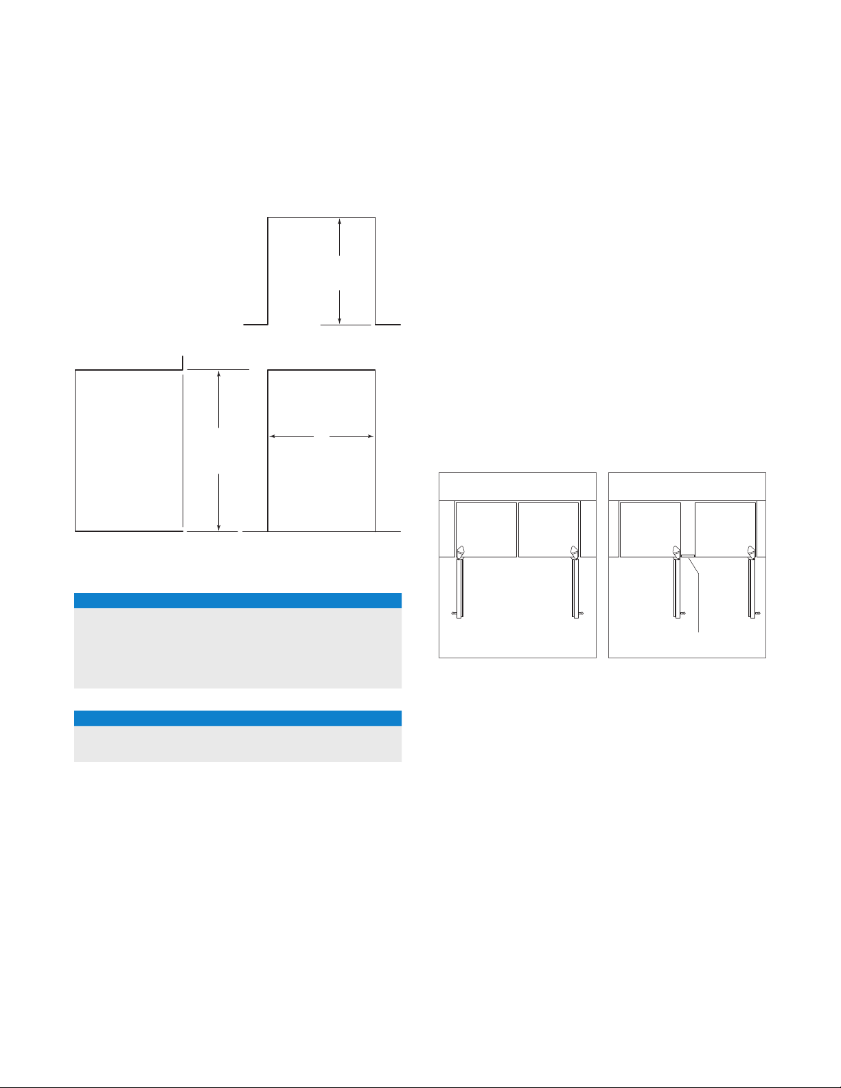
Opening Dimensions
UNDERCOUNTER MODELS
341/2"
(876)
OPENING
HEIGHT
VIEW FRONT VIEW
OPENING WIDTH
24" (610)
OPENING
DEPTH
TOP VIEW
W
DUAL INSTALLATION
If two units are installed side by side, a dual installation kit
may be required. Installations without a custom ller strip
require a dual installation kit. If a dual installation kit is not
specied, a 2"
(51) ller strip is recommended between units.
Dual installations without a ller strip can only be accomplished using two units with opposite hinges. Refer to the
illustrations below.
Dual installation kits are available through an authorized
Sub-Zero dealer. For local dealer information, visit the nd a
showroom section of our website, subzero.com. For questions regarding the installation, call Sub-Zero customer care
at 800-222-7820.
OPENING WIDTH
MODEL W
UC-24R 24" (610)
UC-24BG 24" (610)
UC-24C(I) 24" (610)
UC-24RO 24" (610)
DUAL OPENING WIDTH
MODELS W
Two 24" Models 481/8" (1222)
Dual installation kit required.
WITHOUT FILLER STRIP
Opposite hinges.
FILLER STRIP
Same side hinges.
4 | Sub-Zero Customer Care 800.222.7820
Page 5
SITE PREPARATION
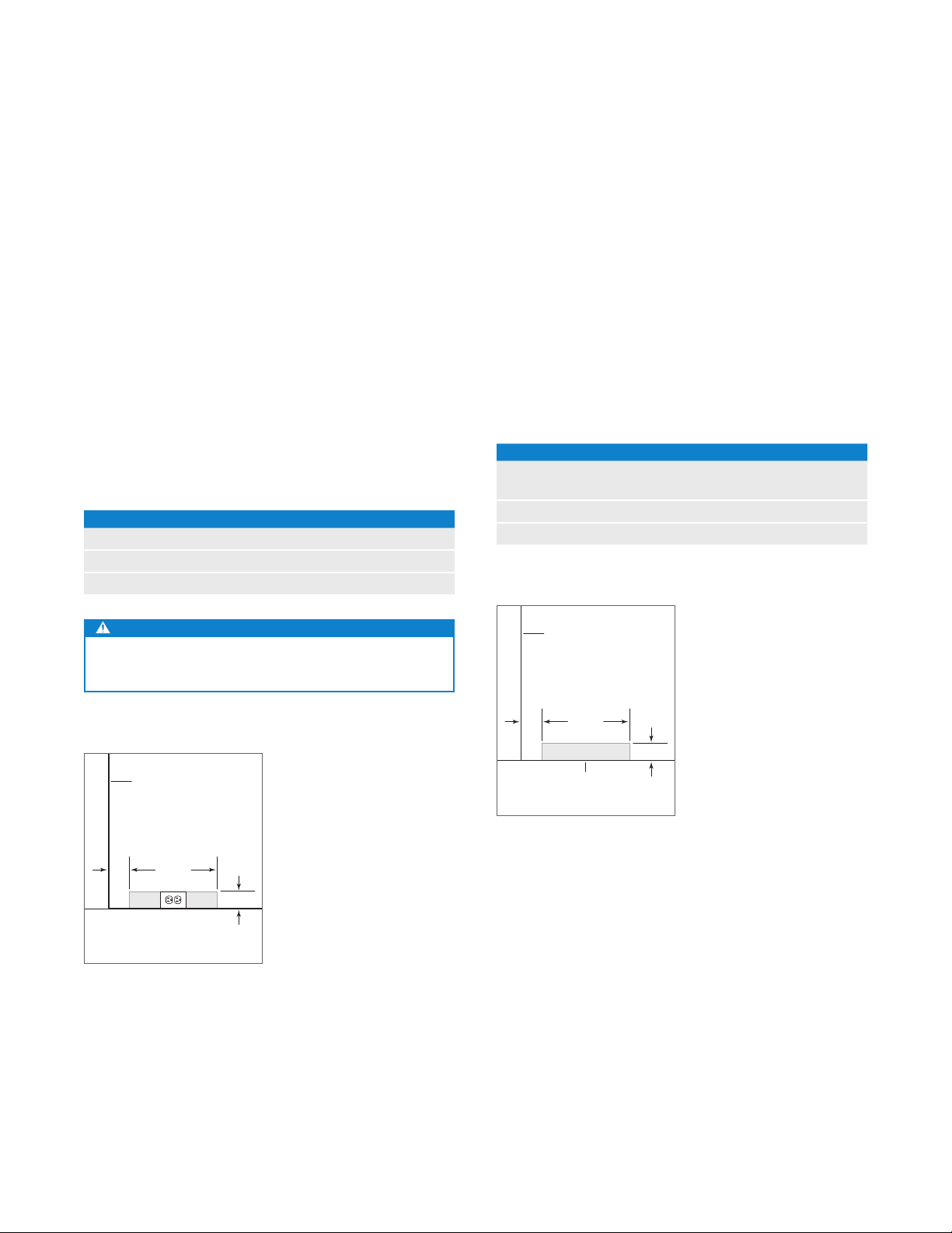
Electrical
Installation must comply with all applicable electrical codes.
The electrical supply should be located within the shaded
area shown in the illustration below. A separate circuit,
servicing only this appliance is required.
IMPORTANT NOTE: The electrical outlet must be placed so
the grounding prong is to the right of the thinner blades.
The outlet must be ush with the back wall.
Model UC-24RO is designed and safe for use in outdoor
applications. When installed outdoors, a ground fault
circuit interrupter (GFCI) is required to reduce the risk of
electrical shock. A GFCI is not recommended for use with
other undercounter models and may cause interruption of
operation.
ELECTRICAL REQUIREMENTS
Electrical Supply 115 VAC, 60 Hz
Service 15 amp
Receptacle 3-prong grounding-type
WARNING
Do not use an extension cord, two-prong adapter or
remove the power cord ground prong.
Plumbing
Installation must comply with all applicable plumbing codes.
For model UC-24CI, the water supply should be located
within the shaded area shown in the illustration below.
The water supply line should be connected to the house
supply with an easily accessible shut-off valve. Do not use
self-piercing valves.
A reverse osmosis system can be used provided there is
constant water pressure of 20–100 psi
to the unit at all times. A copper line is not recommended
for this application.
PLUMBING REQUIREMENTS
Water Supply
Pressure 20–100 psi
Excess Line for Connection 36" (914)
LEFT SIDE
OF OPENING
(1.4–6.9 bar) supplied
1
/4" OD copper, braided
stainless steel or PEX tubing
(1.4–6.9 bar)
LEFT SIDE
OF OPENING
2"
151/2"
(51)
Electrical supply location.
(394)
FLOOR
3" (76)
2"
151/2"
(51)
Water supply location.
(394)
1
AREA EXTENDS
FORWARD ON FLOOR
/2" (13)
3" (76)
subzero.com | 5
Page 6

SITE PREPARATION
Preparation
To operate properly, the door must open a minimum of 90°.
Use a minimum 3"
a 90° door opening.
Uncrate the unit and inspect for damage. Remove and
recycle packing materials. Do not discard the kickplate, antitip bracket, hardware and the leveling legs which hold the
wood base to the bottom of the unit.
(76) ller in corner installations to assure
Anti-Tip Bracket
WARNING
To prevent the unit from tipping forward, the anti-tip
bracket must be installed.
The anti-tip bracket should be attached to the wall behind
the unit with the bracket ange located
of the unit. Refer to the illustration below. Failure to properly
position the anti-tip bracket will prevent proper engagement.
ANTI-TIP
BRACKET
1
/4" (6)
1
/4" (6) above the top
Anti-tip bracket.
6 | Sub-Zero Customer Care 800.222.7820
Page 7

INSTALLATION
Installation
CAUTION
Before moving the unit into position, secure the door
closed and protect any nished ooring.
Use an appliance dolly to move the unit near the opening.
If the unit has been on its back or side, it must stand upright
for a minimum of 24 hours before connecting power.
LEVELING
Level the unit before sliding it into position. Turn each of the
four leveling legs clockwise to raise the unit and counterclockwise to lower. Refer to the illustration below.
DOOR ADJUSTMENT
The top and bottom cabinet hinges are held in place with
three permanent adjustment screws. For adjustments,
loosen the screws, adjust the door and tighten screws.
Refer to the illustration below.
PLACEMENT
Plug the power cord into the grounded outlet and slide the
unit into position.
1
It may be necessary to install the unit
/4" (6) beyond the
front surface of adjacent cabinetry to prevent interference
when the door is opened to 145°. Refer to the full-scale
template on page 11.
TOP DOOR
HINGE
ADJUSTMENT
SCREWS
LEVELING LEGS
Leveling.
Top door hinge.
subzero.com | 7
Page 8

INSTALLATION
Installation
WATER LINE (MODEL UC-24CI)
Purge the water line prior to nal connection to the unit. This
will remove any debris that may be present in the tubing
from installing the new water line.
For model UC-24CI, connect the plastic tubing from the unit
to the house water supply line with the tting connection kit
provided. Check all water line ttings for leaks.
IMPORTANT NOTE: Water lines can not be exposed to
freezing temperatures.
ANCHORING
To anchor, use the optional countertop bracket provided, to
secure the unit to the underside of the countertop. Refer to
the illustration below. If the countertop bracket can not be
utilized, install shims along the top and sides of the unit.
KICKPLATE
Install the kickplate using the two screws provided. Refer
to the illustration below. The kickplate must be removable
for service. The oor cannot interfere with removal. Do not
cover the louvered section of the kickplate.
COUNTERTOP
BRACKET
Anchoring.
KICKPLATE
Kickplate installation.
8 | Sub-Zero Customer Care 800.222.7820
Page 9

301/16"
(764)
LH DOOR SWING
233/4" (603)
151/16"
(382)
31/2"
(89)
35/8"
(92)
215/8" (549)
RH DOOR SWING
7
/8"
(22)
PANEL INSTALLATION
Custom Door Panel
For overlay applications, a custom door panel must be
installed. Panel size is critical for a proper t. To verify panel
requirements and dimensions, refer to the Sub-Zero design
guide at subzero.com/specs.
Finish all sides of custom panels. They may be visible
when the door is open or through the window of glass door
models.
MODELS UC-24R AND UC-24C(I)
Remove the two panel mounting brackets attached to the
front of the door. Place the custom overlay door panel face
down on a protected work surface. Position the plastic template provided, ush with the lower edge of the panel. Verify
proper location for right-hand (RH) or left-hand (LH) door
swing. Mark the holes, remove template and drill pilot holes
for the brackets. Secure mounting brackets with screws
provided.
If the template is not available, position mounting brackets
as indicated in the illustration below.
To install the custom door panel, partially insert a screw in
the center of each mounting position on the hinge side of
the door. Engage the tabbed bracket to the handle side
of the door, then slide the hinge side mounting bracket onto
positioning screws. Slotted holes on the mounting bracket
should slide under screw heads to support the panel. Refer
1
to the illustration below. Panel can be adjusted
/4" (6) up
and down and side to side.
Once the custom panel is in place and properly adjusted,
attach remaining screws to the hinge side mounting bracket,
and install magnetic decorative caps as shown in the illustration below.
DOOR
PANEL
BRACKET
SCREW
CAP
Panel mounting brackets.
Panel installation.
subzero.com | 9
Page 10
PANEL INSTALLATION
Custom Door Panel
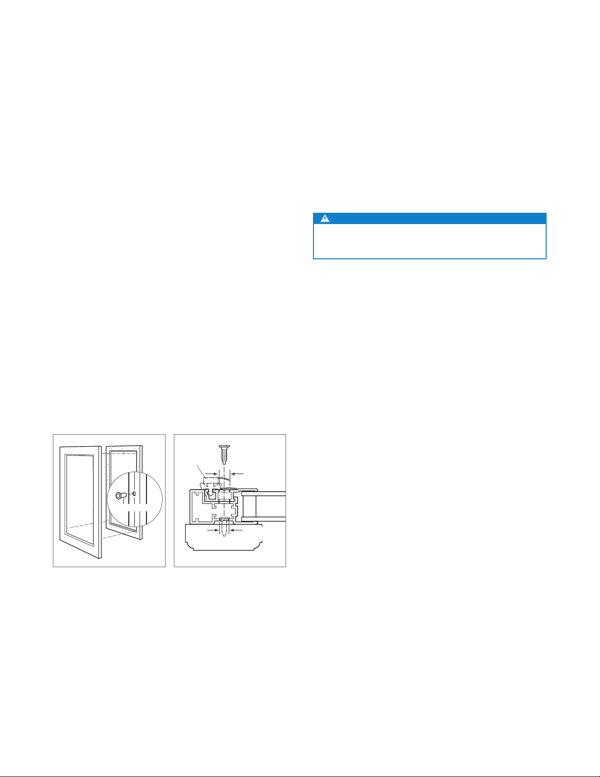
MODEL UC-24BG
The custom overlay door panel is attached using screws
provided through the door frame. Screw locations are
marked on the back of the custom panel using tenon centers inserted into holes of the door frame.
With the unit secured and door closed, hold the custom
panel in desired position on the door. Lightly tap the front
of the panel to locate mounting positions. Remove tenon
centers. Refer to the illustration below.
The door frame has mounting holes to accommodate
Sub-Zero accessory handles. If handle mounting holes are
not utilized, the handle should be attached to the custom
panel prior to mounting. Screw heads may need to be countersunk into the panel for proper alignment.
To mount the custom panel, open the door and use predrilled holes to position the panel. Drive screws into the
panel through black tape on the door frame. Screw holes
are hidden behind the door gasket. Use as many screws as
necessary to secure the custom panel. Refer to the illustration below.
Adjustments can be made to the custom panel with a few
mounting screws in place, but not fully tightened. Once the
proper position is achieved, install and secure all screws.
Cover holes on the inside of the door frame with the cover
patches or plugs provided.
WARNING
Follow all city and state laws when storing, recycling or
discarding unused refrigerators and freezers.
DOOR
FRAMEPANEL
TENON CENTER
Tenon center.
Sub-Zero, Sub-Zero & Design, Dual Refrigeration, The Living Kitchen, Great American Kitchens The Fine Art of Kitchen Design, and Ingredients are registered trademarks and service
marks of Sub-Zero, Inc. Wolf, Wolf & Design, Wolf Gourmet, W & Design and the color red as applied to knobs are registered trademarks and service marks of Wolf Appliance, Inc.
All other trademarks or registered trademarks are property of their respective owners in the United States and other countries.
GASKET
Door frame cross section.
13
/32" (11)
DIAMETER
GLASS
1
/4" (6)
DIAMETER
10 | Sub-Zero Customer Care 800.222.7820
Page 11

FULL-SCALE TEMPLATE
UNDERCOUNTER
UNIT
DOOR CLOSED
3
/4" (19) DOOR PANEL
1
/2"
(13)
ADJACENT
1
/8" (3)
CABINETRY
1
/4"
(6)
1" (25)0"
SCALE
145° door opening (top view).
HINGE AT 145°
OPENING
(DOOR OPENS PAST 145°)
subzero.com | 11
Page 12

UNIDADES DE REFRIGERACIÓN BAJO MOSTRADOR
Contenido
3 Unidad de refrigeración bajo mostrador
4 Dimensiones de abertura
5 Instalación eléctrica
5 Plomería
6 Preparación
6 Soporte antivuelco
7 Instalación
9 Panel de puerta personalizado
11 Plantilla a escala completa
Aviso importante
Para garantizar que este producto sea instalado y operado
de la forma más segura y eciente posible, tome nota de los
siguientes tipos de información resaltada en esta guía:
AVISO IMPORTANTE resalta la información que es
especialmente importante.
PRECAUCIÓN indica una situación en la que se pueden
sufrir heridas leves o provocar daños al producto si no se
siguen las instrucciones.
ADVERTENCIA indica peligro de que se produzcan heridas
graves o incluso la muerte si no se siguen las precauciones.
AVISO IMPORTANTE: En toda esta guía, las dimensiones
entre paréntesis son milímetros, a menos que se especique
lo contrario.
2 | Línea de atención al cliente de Sub-Zero 800.222.7820
Page 13

UNIDADES DE REFRIGERACIÓN BAJO MOSTRADOR
Información del producto
La información importante del producto, incluido el modelo
y número de serie de la unidad se encuentran en la placa de
datos del producto. La placa de datos se encuentra dentro
del gabinete, en el área superior izquierda de la unidad.
Consulte la siguiente ilustración.
Si necesita servicio, póngase en contacto con el centro
de servicio autorizado de Sub-Zero y tenga a la mano el
modelo y número de serie de la unidad. Para obtener los
datos del centro de servicio autorizado de Sub-Zero más
cercano o si tiene preguntas acerca de la instalación, visite
la sección de contacto y soporte técnico en nuestra página
de Internet, subzero.com o llame a la línea de atención al
cliente de Sub-Zero al 800-222-7820.
PLACA DE DATOS
Herramientas y materiales
• Destornilladores (estándar y Phillips).
• Taladro eléctrico y brocas.
• Juego de llaves estándar y de vaso.
• Nivel de 2'.
• Cortador de tubos (modelo UC-24CI).
• 3' de tubería de cobre, trenzada de acero inoxidable o
PEX de
• Válvula de asiento (modelo UC-24CI).
• Material para proteger la casa, el piso y los gabinetes
durante la instalación.
1
/4" de diámetro exterior (modelo UC-24CI).
Ubicación de la placa de datos.
subzero.com | 3
Page 14

VIST
PREPARACIÓN DEL SITIO
Dimensiones de abertura
MODELOS BAJO MOSTRADOR INSTALACIÓN DOBLE
VISTA SUPERIOR
24" (610)
PROFUNDIDAD DE
LA ABERTURA
24" (610)
PROFUNDIDAD DE
LA ABERTURA
A LATERAL
341/2" (876)
ALTURA DE
LA ABERTURA
W
ANCHURA DE
LA ABERTURA
VISTA FRONTAL
ANCHURA DE LA ABERTURA
MODELO W
UC-24R 24" (610)
UC-24BG 24" (610)
UC-24C(I) 24" (610)
UC-24RO 24" (610)
Si se instalan dos unidades lado a lado, puede ser necesario un kit de instalación doble. Las instalaciones sin una
tira de relleno personalizada requieren un kit de instalación
doble. Si el uso de un kit de instalación doble no está
especicado, se recomienda utilizar una tira de relleno de
(51) entre las unidades. Las instalaciones dobles sin una
2"
tira de relleno sólo se pueden realizar cuando se utilizan dos
unidades con bisagras opuestas. Consulte las siguientes
ilustraciones.
Los kits de instalación doble están disponibles a través de
un distribuidor autorizado de Sub-Zero. Para obtener más
información acerca de los distribuidores locales, visite la
sección para encontrar una sala de exhibición de nuestro
sitio web, subzero.com. Para preguntas sobre la instalación,
comuníquese a la línea de atención al cliente de Sub Zero al
800-222-7820.
ANCHURA DE ABERTURA DOBLE
MODELOS W
Dos modelos de 24" (610) 481/8" (1222)
Se requiere kit de instalación doble.
4 | Línea de atención al cliente de Sub-Zero 800.222.7820
SIN TIRA DE RELLENO
WITHOUT FILLER STRIP
Bisagras opuestas.
TIRA DE RELLENO
FILLER STRIP
Bisagras en el mismo lado.
Page 15

PREPARACIÓN DEL SITIO
SHUT-OFF
VALV E
151/2"
(394)
9" (229)
11/2"
(38)
6"
(152)
WATER LINE
BOTTOM ENTRY
Instalación eléctrica
La instalación debe cumplir con todos los códigos eléctricos aplicables.
El suministro eléctrico debe colocarse dentro del área sombreada que se muestra en la siguiente ilustración. Es necesario un circuito independiente, que dé servicio únicamente
a este aparato.
AVISO IMPORTANTE: El tomacorriente eléctrico debe colo-
carse de tal forma que la clavija con conexión a tierra quede
a la derecha de las aspas más delgadas. El tomacorriente
debe quedar al ras de la pared trasera.
El Modelo UC-24RO está diseñado y es seguro para su uso
en aplicaciones al aire libre. Cuando se instala al aire libre,
es necesario instalar un circuito de fallos de conexión a
tierra (GFCI, por sus siglas en inglés) para reducir el riesgo
de descarga eléctrica. No es recomendable utilizar un GFCI
con otros modelos bajo mostrador ya que puede interrumpir
el funcionamiento de la unidad.
REQUISITOS ELÉCTRICOS
Suministro eléctrico 115 V CA, 60 Hz
Interruptor de circuito 15 amperes
Receptáculo Conexión a tierra de 3 clavijas
Plomería
La instalación debe cumplir con todos los códigos de
plomería aplicables.
Para el modelo UC-24CI, el suministro de agua debe
colocarse dentro del área sombreada que se muestra
en la siguiente ilustración. La línea del suministro de
agua debe conectarse al suministro doméstico con
una válvula de cierre de fácil acceso. Evite utilizar
válvulas- autoperforantes.
Se puede utilizar un sistema de ósmosis inversa siempre
y cuando la presión del agua que llegue a la unidad se
mantenga de forma constante entre 20 a 100 psi
bares)
en todo momento. No es recomendable utilizar una
línea de cobre para esta aplicación.
REQUISITOS DE PLOMERÍA
Línea de suministro de agua Tubería de cobre, trenzada de
acero inoxidable o PEX de 1/4"
de diámetro exterior.
Presión del agua De 20 a 100 psi
Línea de exceso de agua para
la conexión
(de 1.4 a 6.9
(de 1.4 a 6.9 bares)
36" (914)
ADVERTENCIA
No utilice un cable de extensión, adaptador de dos
clavijas ni retire la clavija con conexión a tierra del
cable de alimentación.
LADO IZQUIERDO
DE LA ABERTURA
2" (51)
151/2"
(394)
3" (76)
VISTA FRONTAL
Ubicación del suministro
eléctrico.
EL ÁREA SOMBREADA
SE EXTIENDE
DESDE LA PARTE
POSTERIOR DE LA PARED
2" (51)
VISTA FRONTAL
151/2"
(394)
1
/2" (13)
3" (76)
Ubicación del suministro de agua.
subzero.com | 5
Page 16

PREPARACIÓN DEL SITIO
Preparación
Para un funcionamiento apropiado, la puerta debe abrir a
un ángulo mínimo de 90°. Utilice un relleno de 3"
mínimo en las instalaciones esquinadas para asegurar que
la puerta se abra a 90°.
Desembale la unidad e inspeccione si tiene algún daño.
Retire y recicle los materiales de embalaje. No deseche el
zócalo, el soporte antivuelco, las piezas de montaje ni las
patas niveladoras que soportan la base de madera a la
parte inferior de la unidad.
(76) como
Soporte antivuelco
ADVERTENCIA
Para evitar que la unidad se incline hacia delante y proporcionar una instalación estable, la unidad debe estar
asegurada en su lugar con el soporte antivuelco.
El soporte antivuelco debe sujetarse a la pared detrás de
la unidad con la pestaña del soporte que sobresale
por encima de la parte superior de la unidad. Consulte la
siguiente ilustración. No colocar correctamente el soporte
antivuelco impedirá que la unidad quede bien enganchada.
SOPORTE
ANTIVUELCO
1
/4" (6)
1
/4" (6)
Soporte antivuelco.
6 | Línea de atención al cliente de Sub-Zero 800.222.7820
Page 17

INSTALACIÓN
Instalación
PRECAUCIÓN
Antes de mover la unidad a su posición, asegúrese de
que la puerta esté cerrada y proteja cualquier suelo
con acabado.
Utilice una plataforma rodante para mover la unidad cerca
de la abertura.
Si la unidad ha estado o está acostada o de lado, debe
ponerla de pie y dejarla así durante un mínimo de 24 horas
antes de conectarla al suministro eléctrico.
NIVELACIÓN
Nivele la unidad antes de colocarla en su sitio. Gire cada
una de las patas niveladoras en sentido de las manecillas
del reloj para levantar la unidad o en sentido opuesto de
las manecillas del reloj para bajarla. Consulte la siguiente
ilustración.
AJUSTE DE LA PUERTA
Las bisagras superiores e inferiores del gabinete se jan
en su lugar con tres tornillos de ajuste permanente. Para
realizar ajustes, aoje los tornillos, ajuste la puerta y vuelva
a apretar los tornillos. Consulte la siguiente ilustración.
COLOCACIÓN
Conecte el cable de alimentación a la conexión a tierra y
deslice la unidad en su sitio.
1
Puede que sea necesario instalar la unidad
/4" (6) fuera de
la supercie delantera de los gabinetes adyacentes para
evitar interferencias al abrir la puerta a 145°. Consulte la
plantilla a escala completa de la página 11.
BISAGRA SUPERIOR
DE LA PUERTA
TORNILLOS
DE AJUSTE
PATAS NIVELADORAS
Nivelación.
Bisagra superior de la puerta.
subzero.com | 7
Page 18

INSTALACIÓN
Instalación
LÍNEA DE AGUA (MODELO UC-24CI)
Purgue la línea de agua antes de hacer la conexión nal a la
unidad. Esto eliminará cualquier residuo que pueda haber
quedado en la tubería al instalar la nueva línea de agua.
Para el modelo UC-24CI, conecte el tubo de plástico de la
unidad al suministro de agua doméstico con el kit de instalación de la conexión que viene con la unidad. Revise todos
los accesorios de la línea de agua para detectar fugas.
AVISO IMPORTANTE: Las líneas de agua no pueden quedar
expuestas a temperaturas de congelación.
ANCLAJE
Para el anclaje, utilice el soporte de mostrador opcional proporcionado, para asegurar la unidad a la parte inferior del
mostrador. Consulte la siguiente ilustración. Si no es posible
utilizar el soporte del mostrador, instale cuñas a lo largo de
la parte superior y los lados de la unidad.
ZÓCALO
Instale el zócalo con los dos tornillos proporcionados. Consulte la siguiente ilustración. El zócalo debe ser desmontable para sacarlo cuando sea necesario dar servicio a la
unidad. El suelo no debe interferir al desmontarlo. No cubra
la sección tipo persiana del zócalo.
SOPORTE DEL
MOSTRADOR
Anclaje.
ZÓCALO
Instalación del zócalo.
8 | Línea de atención al cliente de Sub-Zero 800.222.7820
Page 19

301/16"
(764)
GIRO DE LA PUERTA
MANO IZQUIERDA (LH)
233/4" (603)
151/16"
(382)
31/2"
(89)
35/8"
(92)
215/8" (549)
GIRO DE LA PUERTA
MANO DERECHA (RH)
7
/8"
(22)
INSTALACIÓN DE LOS PANELES
Panel de puerta personalizado
Para aplicaciones revestibles, es necesario instalar un panel
de puerta personalizado. El tamaño del panel es fundamental para un buen ajuste. Para vericar los requisitos y
dimensiones del panel, consulte la guía de diseño de
Sub-Zero en subzero.com/specs.
Asegúrese de que todos los lados de los paneles personalizados tengan un buen acabado. Estos pueden verse al
abrir la puerta o a través de la ventana de los modelos con
puertas de vidrio.
MODELOS UC-24R Y UC-24C(I)
Retire los dos soportes de montaje del panel unidos a la
parte delantera de la puerta. Coloque el panel de puerta
revestible personalizado boca abajo sobre una supercie de
trabajo protegida. Coloque la plantilla de plástico proporcionada, a ras con el borde inferior del panel. Verique la
ubicación correcta del giro de la puerta para mano derecha
(RH) o izquierda (LH). Marque los oricios, retire la plantilla
y taladre los oricios guía para los soportes. Asegure los
soportes de montaje con los tornillos proporcionados.
Si no tiene una plantilla a la mano, coloque los soportes de
montaje como se indica en la siguiente ilustración.
Para instalar el panel de puerta personalizado, inserte
parcialmente un tornillo en el centro de cada posición de
montaje del lado de la bisagra de la puerta. Enganche el
soporte con pestañas en el lado de la manija de la puerta,
luego deslice el soporte de montaje del lado de la bisagra
en los tornillos de posicionamiento. Los oricios ranurados
del soporte de montaje deben deslizarse por debajo de las
cabezas de los tornillos para dar soporte al panel. Consulte
1
la siguiente ilustración. El panel se puede ajustar
/4" (6)
hacia arriba y hacia abajo y de lado a lado.
Una vez que el panel personalizado se encuentra en su
posición y ajustado correctamente, coloque los tornillos
restantes en el soporte de montaje del lado de la bisagra e
instale las tapas decorativas magnéticas como se muestra
en la ilustración de abajo.
SOPORTE
DEL PANEL
DE LA
PUERTA
TORNILLO
Soportes de montaje del panel.
Instalación del panel.
TAPA
subzero.com | 9
Page 20

INSTALACIÓN DE LOS PANELES
Panel de puerta personalizado
MODELO UC-24BG
El panel de puerta revestible personalizado se sujeta con
los tornillos proporcionados a través del marco de la puerta.
Las ubicaciones de los tornillos se marcan en la parte
trasera del panel personalizado mediante centros de espiga
insertados en los oricios del marco de la puerta.
Una vez que la unidad está asegurada y la puerta cerrada, sujete el panel personalizado en la posición deseada
sobre la puerta. Dé un golpe suave al frente del panel para
localizar las posiciones de montaje. Retire los centros de
espiga. Consulte la siguiente ilustración.
El marco de la puerta tiene oricios de montaje para alojar
las manijas adicionales de Sub-Zero. Si no utiliza los oricios de montaje de las manijas, debe jar la manija al panel
personalizado antes del montaje. Puede que sea necesario avellanar las cabezas de los tornillos en el panel para
obtener una buena alineación.
Para montar el panel personalizado, abra la puerta y utilice
los oricios previamente perforados para colocar el panel
en posición. Introduzca los tornillos en el panel a través de
la cinta negra en el marco de la puerta. Los oricios para los
tornillos están ocultos bajo una solapa en el empaque de la
puerta. Necesita levantar la solapa para insertar los tornillos.
Utilice todos los tornillos que sean necesarios para asegurar
el panel personalizado. Consulte la siguiente ilustración.
Una vez que tenga unos cuantos tornillos de montaje en
su lugar, pero no bien apretados, puede realizar ajustes al
panel personalizado. Una vez que el panel esté bien puesto,
instale y asegure todos los tornillos.
Cubra los oricios en el marco del interior de la puerta con
las cubiertas o tapones proporcionados.
ADVERTENCIA
Siga todas las leyes estatales y locales para almacenar,
reciclar o desechar los refrigeradores y congeladores
no utilizados.
EMPAQUE
PANEL
PERSONALIZADO
CENTRO DE ESPIGA
Centros de espiga.
Sub-Zero, Sub-Zero & Design, Dual Refrigeration, The Living Kitchen, Great American Kitchens The Fine Ar t of Kitchen Design e Ingredients son marcas comerciales registradas y
marcas de servicio de Sub-Zero, Inc. Wolf, Wolf & Design, Wolf Gourmet, W & Design y el color rojo aplicado a las perillas son marcas comerciales registradas y marcas de servicio
de Wolf Appliance, Inc. Todas las demás marcas comerciales o marcas comerciales registradas son propiedad de sus respectivos propietarios en los Estados Unidos y otros países.
10 | Línea de atención al cliente de Sub-Zero 800.222.7820
MARCO
DE LA
PUERTA
Sección transversal del marco
de la puerta.
13
/32" (11)
DE DIÁMETRO
CRISTAL
1
/4" (6)
DE DIÁMETRO
Page 21

PLANTILLA A ESCALA COMPLETA
UNIDAD BAJO
MOSTRADOR
PUERTA CERRADA
PANEL DE LA PUERTA DE
3
/
4" (19)
1
/2"
(13)
GABINETES
1
ADYACENTES
/8" (3)
1
/4"
(6)
1" (25)0"
ESCALA
Abertura de la puerta a 145° (vista superior).
BISAGRA A 145
AL ABRIR (LA PUERTA
ABRE A MÁS DE 145
˚
subzero.com | 11
)
˚
Page 22

RÉFRIGÉRATION SOUS LE COMPTOIR
Table des matières
3 Réfrigération sous le comptoir
4 Dimensions de l’ouverture
5 Puissance
5 Plomberie
6 Préparation
6 Support antibasculement
7 Installation
9 Panneau de porte personnalisé
11 Gabarit pleine échelle
Remarque importante
Pour s’assurer que ce produit est installé et utilisé en toute
sécurité et aussi efcacement que possible, prenez note des
types de renseignement mis en évidence tout au long de ce
guide :
REMARQUE IMPORTANTE met en évidence des renseigne-
ments qui sont particulièrement importants.
MISE EN GARDE indique une situation où une blessure
mineure ou des dommages au produit peuvent se produire
si les directives ne sont pas respectées.
AVERTISSEMENT décrit un danger qui peut causer une
blessure grave ou la mort si les précautions ne sont pas
respectées.
REMARQUE IMPORTANTE : tout au long de ce guide, les
dimensions entre parenthèses sont en millimètres à moins
d’indication contraire.
2 | Service à la clientèle de Sub-Zero 800.222.7820
Page 23

RÉFRIGÉRATION SOUS LE COMPTOIR
Renseignements sur le produit
Des renseignements importants sur le produit, y compris les
numéros de modèle et de série de votre unité, se trouvent
sur la plaque signalétique du produit. La plaque signalétique
est située à l’intérieur de l’armoire dans la zone supérieure
gauche de l’unité. Reportez-vous à l’illustration ci-dessous.
Si vous avez besoin de service, communiquez avec le
service Sub-Zero certié par l’usine et ayez les numéros de
modèle et de série de l’unité à la portée de la main. Pour
obtenir le nom du centre de service Sub-Zero certié par
l’usine près de chez vous ou si vous avez des questions
concernant l’installation, consultez la section Contact et
assistance de notre site Web, subzero.com ou appelez le
service à la clientèle de Sub-Zero au 800-222-7820.
PLAQUE SIGNALÉTIQUE
Outils et matériaux
• Tournevis—standard et cruciforme.
• Perceuse électrique et forets.
• Ensemble de clés et douilles standard.
• Niveau de 2 pi.
• Coupe-tube (modèle UC-24CI).
• 3 pi de tube PEX ou en acier inoxydable tressé en cuivre
1
/4 po de diamètre extérieur (modèle UC-24CI).
de
• Robinet-vanne à étrier (modèle UC-24CI).
• Des matériaux pour protéger la résidence, le plancher et
les armoires pendant l’installation.
Emplacement de la plaque
signalétique.
subzero.com | 3
Page 24

VUE DE PR
PRÉPARATION DU SITE
Dimensions de l’ouverture
MODÈLES SOUS LE COMPTOIR INSTALLATION DOUBLE
VUE DE DESSUS
PROFONDEUR
D'OUVERTURE DE
24 po (610)
PROFONDEUR
D'OUVERTURE DE
24 po (610)
OFIL
HAUTEUR
D'OUVERTURE DE
34 1/2 po (876)
LARGEUR
D'OUVERTURE DE
W
VUE DE FACE
LARGEUR D'OUVERTURE DE
MODÈLE W
UC-24R 24 po (610)
UC-24BG 24 po (610)
UC-24C(I) 24 po (610)
UC-24RO 24 po (610)
Si deux unités sont installées côté à côte, une trousse
d'installation double pourra être requise. Les installations
sans languette de remplissage personnalisée nécessitent une trousse d'installation double. Si une trousse
d'installation double n'est pas précisée, une languette de
remplissage de 2 po
(51) est recommandée entre les unités.
Les installations doubles sans languette de remplissage
ne peuvent être réussies qu'en utilisant deux unités avec
des charnières opposées. Reportez-vous aux illustrations
ci-dessous.
Les trousses d'installation double sont offertes par les
dépositaires Sub-Zero autorisés. Pour obtenir des renseignements sur votre dépositaire local, visitez la section salle
d'exposition de notre site Web, subzero.com. Si vous avez
des questions au sujet de l'installation, communiquez avec
le service à la clientèle de Sub-Zero au 800-222-7820.
LARGEUR D'OUVERTURE DOUBLE
MODÈLES W
Deux modèles de 24 po (610) 481/8 po (1222)
Trousse d'installation double requise.
4 | Service à la clientèle de Sub-Zero 800.222.7820
SANS LANGUETTE DE REMPLISSAGE
WITHOUT FILLER STRIP
Charnières opposées.
LANGUETTE DE REMPLISSAGE
FILLER STRIP
Charnières du même côté.
Page 25

PRÉPARATION DU SITE
SHUT-OFF
VALV E
151/2"
(394)
9" (229)
11/2"
(38)
6"
(152)
WATER LINE
BOTTOM ENTRY
Puissance
L’installation doit se conformer à tous les codes électriques
applicables.
L’alimentation électrique doit se trouver à l’intérieur de la
zone ombragée indiquée dans l’illustration ci-dessous. Un
circuit séparé servant uniquement cet appareil est requis.
REMARQUE IMPORTANTE : la prise doit être placée de
façon à ce que la broche de mise à la terre se trouve à la
droite des broches plus minces. La prise doit être à égalité
avec le mur arrière.
Le modèle UC-24RO est conçu pour être utilisé sans danger
dans les applications extérieures. Lors d’une installation
à l’extérieur, un disjoncteur de fuite de terre (GFCI) est
requis pour réduire le risque de choc électrique. Un disjoncteur de fuite de terre n’est pas recommandé pour les
autres modèles sous le comptoir et peut interrompre le
fonctionnement.
INSTALLATIONS ÉLECTRIQUES
Alimentation électrique 115 volts CA, 60 Hz
Disjoncteur 15 ampères
Prise mise à la terre à trois broches
Plomberie
L’installation doit se conformer à tous les codes de plomberie applicables .
Pour le modèle UC-24CI, l’alimentation en eau doit se
trouver à l’intérieur de la zone ombragée indiquée dans
l’illustration ci-dessous. Le tuyau d’alimentation en eau
doit être relié à l’alimentation de la maison avec un robinet
d’arrêt facilement accessible. N’utilisez pas des vannes à
auto-perçage.
Un système à osmose inverse peut être utilisé à condition
qu’il y ait une pression d’eau constante de 20 à 100 psi
à 6,9 bars)
vers l’unité en tout temps. Une conduite en cuivre
n’est pas recommandée pour cette application.
EXIGENCES DE PLOMBERIE
Tuyau d’alimentation en eau tube PEX ou en acier inoxydable
tressé en cuivre de 1/4 po de
diamètre extérieur
Pression d’eau 20–100 psi
Tuyau d’alimentation en eau
supplémentaire pour connexion
(1,4-6,9 bars)
(1,4
36 po (914)
AVERTISSEMENT
N’utilisez pas une rallonge ou un adaptateur à deux
broches et ne retirez pas la broche de mise à la terre
du cordon d’alimentation.
CÔTÉ GAUCHE
DE L'OUVERTURE
2 po (51)
151/2 po
(394)
3 po (76)
VUE DE FACE
Emplacement de l’alimentation
électrique.
LA ZONE OMBRAGÉE SE
PROLONGE DE
DE L'ARRIÈRE DU MUR
2 po (51)
1
151/2 po
(394)
VUE DE FACE
/2 PO (13)
3 po (76)
Emplacement de l’alimentation
en eau.
subzero.com | 5
Page 26

1
/4 po (6)
SUPPORT
ANTIBASCULEMENT
PRÉPARATION DU SITE
Préparation
Pour qu’elle fonctionne correctement, la porte doit s’ouvrir
d’au moins 90°. Utilisez un remplissage d’au moins 3 po
dans les installations en coin pour vous assurer que la porte
s’ouvre à 90°.
Sortez l’unité de la boîte et examinez-la pour vous assurer
qu’elle n’est pas endommagée. Retirez et recyclez les
matériaux d’emballage. Ne jetez pas la plaque de protection, le support antibasculement, la quincaillerie et les pieds
de mise à niveau qui retiennent la base en bois au fond de
l’unité.
(76)
Support antibasculement
AVERTISSEMENT
Pour empêcher l’unité de basculer vers l’avant et
obtenir une installation stable, elle doit être xée en
place au moyen du support antibasculement.
Le support antibasculement doit être xé au mur derrière
l’unité avec la bride du support située à une distance de
(6) au-dessus de la partie supérieure de l’unité. Reportez-
po
vous à l’illustration ci-dessous. Si le support antibasculement n’est pas aligné adéquatement, il ne s’enclenchera
pas correctement.
1
/4
Support antibasculement.
6 | Service à la clientèle de Sub-Zero 800.222.7820
Page 27

INSTALLATION
Installation
MISE EN GARDE
Avant de mettre l’unité en place, sécurisez la porte en
position fermée et protégez tout plancher ni.
Utilisez un chariot à appareil pour déplacer l’unité près de
l’ouverture.
Si l’unité a été posée sur le dos ou le côté, elle doit être
mise debout pendant au moins 24 heures avant de relier
l’alimentation.
NIVELLEMENT
Nivelez l’unité avant de la glisser en position. Tournez
chacun des quatre pieds de mise à niveau dans le sens
horaire pour soulever l’appareil et dans le sens antihoraire
pour l’abaisser. Reportez-vous à l’illustration ci-dessous.
RÉGLAGE DE LA PORTE
Les charnières supérieures et inférieures de l’armoire sont
tenues en place avec trois vis de réglage permanentes. Pour
effectuer des réglages, desserrez les vis, réglez la porte et
serrez les vis. Reportez-vous à l’illustration ci-dessous.
POSITIONNEMENT
Branchez le cordon d’alimentation dans une prise mise à la
terre et glissez l’unité en place.
Il peut s’avérer nécessaire d’installer l’unité à une distance
1
/4 po (6) au-delà de la surface avant des armoires adja-
de
centes pour éviter toute interférence lorsque la porte est
ouverte à 145°. Reportez-vous au gabarit pleine échelle à la
page 11.
CHARNIÈRE SUPÉRIEURE
DE LA PORTE
VIS DE
RÉGLAGE
PIEDS DE MISE À NIVEAU
Nivellement.
Charnière supérieure de la
porte.
subzero.com | 7
Page 28

INSTALLATION
Installation
TUYAU D’ALIMENTATION EN EAU (MODÈLE UC-24CI)
Purgez le tuyau d’alimentation en eau avant d’effectuer
la dernière connexion vers l’unité. Ceci éliminera tous
les débris qui pourraient se trouver dans le tube suite à
l’installation du nouveau tuyau d’alimentation en eau.
Pour le modèle UC-24CI, reliez le tube en plastique de
l’unité à l’alimentation en eau de la résidence au moyen de
la trousse de connexion de raccords fournie. Vériez que
tous les raccords du tuyau d’alimentation en eau n’aient pas
de fuites.
REMARQUE IMPORTANTE : les tuyaux d’alimentation en eau
ne doivent pas être exposés au gel.
ANCRAGE
Pour ancrer, utilisez le support de comptoir en option fourni
pour sécuriser l’unité à la partie inférieure du comptoir.
Reportez-vous à l’illustration ci-dessous. Si le support de
comptoir ne peut pas être utilisé, installez des calles le long
du dessus et des côtés de l’unité.
PLAQUE DE PROTECTION
Installez la plaque de protection au moyen des deux vis
fournies. Reportez-vous à l’illustration ci-dessous. La
plaque de protection doit pouvoir être enlevée pour toute
réparation. Le plancher ne doit pas nuire à l’enlèvement.
Ne couvrez pas la section persiennée de la plaque de
protection.
SUPPORT DE
COMPTOIR
8 | Service à la clientèle de Sub-Zero 800.222.7820
Ancrage.
PLAQUE DE PROTECTION
Installation de la plaque de
protection.
Page 29

SUPPORT
DU PANNEAU
DE PORTE
CAPUCHON
BLOCAGE
301/16 po
(764)
OUVERTURE DE PORTE
VERS LA GAUCHE
233/4 po (603)
151/16 po
(382)
31/2 po
(89)
35/8 po
(92)
215/8 po (549)
OUVERTURE DE PORTE
VERS LA DROITE
7
/8 po
(22)
INSALLATION DES PANNEAUX
Panneau de porte personnalisé
Pour les applications à revêtement, un panneau de porte
personnalisé doit être installé. La taille du panneau est critique pour obtenir un ajustement approprié. Pour vérier les
exigences et les dimensions des panneaux, reportez-vous
au guide de conception Sub-Zero à subzero.com/specs.
Finissez tous les côtés des panneaux personnalisés. Ils
pourront être visibles lorsque la porte est ouverte ou par la
fenêtre des modèles à porte en verre.
MODÈLES UC-24R ET UC-24C(I)
Retirez les deux supports de montage du panneau xés à
l’avant de la porte. Placez le panneau de porte à revêtement
personnalisé vers le bas sur une surface de travail protégée.
Placez le gabarit en plastique fourni à égalité avec le rebord
inférieur du panneau. Vériez l’emplacement approprié pour
l’ouverture de la porte vers la droite (D) ou la gauche (G).
Marquez les trous, retirez le gabarit et percez les avant-trous
pour les supports. Fixez les supports de montage avec les
vis fournies.
Si le gabarit n’est pas disponible, placez les supports de
montage comme il est indiqué dans l’illustration ci-dessous.
Pour installer le panneau de porte personnalisé, insérez
partiellement une vis au centre de chaque position de montage du côté charnière de la porte. Enclenchez le support
à onglet dans le côté poignée de la porte, puis glissez le
support de montage du côté charnière dans les vis de positionnement. Les trous allongés sur le support de montage
doivent se glisser sous les têtes de vis pour soutenir le panneau. Reportez-vous à l’illustration ci-dessous. Le panneau
1
peut être ajusté de
/4 po (6) vers le haut et le bas et d’un
côté ou l’autre.
Une fois le panneau personnalisé en place et correctement
ajusté, xez les vis restantes sur le support de montage du
côté de la charnière et installez les capuchons décoratifs
magnétiques comme dans l’illustration ci-dessous.
Supports de montage du
panneau.
Installation du panneau.
subzero.com | 9
Page 30

INSALLATION DES PANNEAUX
Panneau de porte personnalisé
MODÈLE UC-24BG
Le panneau de porte à revêtement personnalisé est xé au
moyen de vis fournies dans l’encadrement de la porte. Les
emplacements des vis sont marqués à l’arrière du panneau
personnalisé au moyen de centres de tenon insérés dans les
trous de l’encadrement de la porte.
Une fois l’unité sécurisée et la porte fermée, tenez le panneau personnalisé à la position désirée sur la porte. Tapez
légèrement le devant du panneau pour repérer les positions
de montage. Retirez les centres de tenon. Reportez-vous à
l’illustration ci-dessous.
L’encadrement de la porte possède des trous de montage
pour accommoder les poignées accessoires de Sub-Zero.
Si les trous de montage de poignée ne sont pas utilisés, la
poignée doit être xée au panneau personnalisé avant le
montage. Les têtes de vis peuvent devoir être fraisées dans
le panneau pour obtenir un ajustement adéquat.
Pour monter le panneau personnalisé, ouvrez la porte
et utilisez les trous pré-percés pour placer le panneau.
Enfoncez les vis dans le panneau à travers le ruban noir sur
l’encadrement de la porte. Des trous de vis sont cachés
sous un rabat sur le joint de la porte. Il faut soulever le
rabat pour insérer les vis. Utilisez autant de vis que nécessaire pour xer le panneau personnalisé. Reportez-vous à
l’illustration ci-dessous.
Des réglages peuvent être effectués au panneau personnalisé avec quelques vis de montage en place, mais pas
lorsqu’elles sont complètement serrées. Une fois la position
désirée obtenue, installez et sécurisez toutes les vis.
Couvrez les trous à l’intérieur de l’encadrement de la porte
avec les pastilles ou les bouchons fournis.
AVERTISSEMENT
Respectez toutes les lois provinciales et locales lors de
l’entreposage, le recyclage ou l’élimination des réfrigérateurs et des congélateurs non utilisés.
JOINT
PANNEAU
PERSONNALISÉ
CENTRE DU TENON
Centres du tenon.
Sub-Zero, Sub-Zero & Design, Dual Refrigeration, The Living Kitchen, Great American Kitchens The Fine Art of Kitchen Design et Ingredients sont des marques déposées et de service
de Sub-Zero, Inc. Wolf, Wolf & Design, Wolf Gourmet, W & Design et la couleur rouge qui se trouve sur les boutons sont des marques déposées et de service de Wolf Appliance, Inc.
Toutes les autres marques de commerce ou déposées appartiennent à leurs propriétaires respectifs aux États-Unis et dans d’autres pays.
10 | Service à la clientèle de Sub-Zero 800.222.7820
ENCADREMENT
DE PORTE
Vue transversale de l’encadrement de la porte.
13
/32 po (11)
DE DIAMÈTRE
VERRE
1
/4 po (6)
DE DIAMÈTRE
Page 31

GABARIT PLEINE ÉCHELLE
UNITÉ SOUS
LE COMPTOIR
PORTE FERMÉE
PANNEAU DE PORTE DE 3/4 po
(19)
1
/2 po
(13)
1
/8 po (3)
ARMOIRE
ADJACENTE
1
/4 po
(6)
1 po (25)0 po
ÉCHELLE
Ouverture de porte de 145° (vue de dessus).
CHARNIÈRE
À 145° D'OUVERTURE
(LA PORTE S'OUVRE
AU-DELÀ DE 145°)
subzero.com | 11
Page 32

SUB-ZERO, INC. P.O. BOX 44848 MADISON, WI 53744 SUBZERO.COM 800.222.7820
7031171 REV-A 2/2014
 Loading...