

Page 1

UNDERCOUNTER ICE MAKER
INSTALLATION GUIDE
SPECIFICATIONS, INSTALLATION, AND MORE
Page 2

UNDERCOUNTER ICE MAKER
Contents
3 Undercounter Ice Maker
4 Opening Dimensions
5 Electrical
6 Plumbing
7 Installation
10 Custom Panel
11 Completion
Features and specications are subject to change at any
time without notice. Visit subzero.com/specs for the most
up-to-date information.
Important Note
To ensure this product is installed and operated as safely
and efciently as possible, take note of the following types
of highlighted information throughout this guide:
IMPORTANT NOTE highlights information that is especially
important.
CAUTION indicates a situation where minor injury or product
damage may occur if instructions are not followed.
WARNING states a hazard that may cause serious injury or
death if precautions are not followed.
IMPORTANT NOTE: Throughout this guide, dimensions in
parentheses are millimeters unless otherwise specied.
IMPORTANT NOTE: Save these instructions for the local
electrical inspector.
2 | Sub-Zero Customer Care 800.222.7820
Page 3
UNDERCOUNTER ICE MAKER
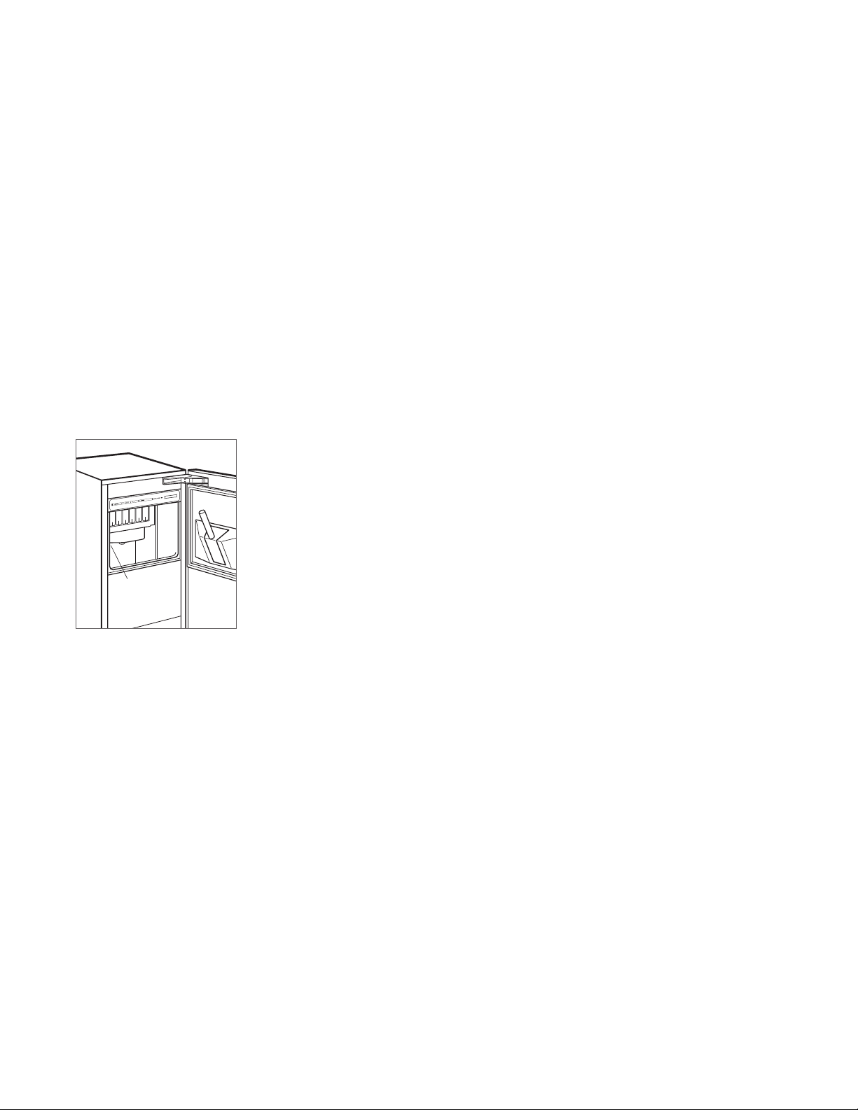
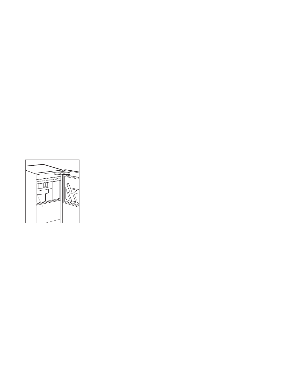
Product Information
Important product information, including the model and
serial number, are listed on the product rating plate. The
rating plate is located in the upper left corner of the ice
storage bin, on the back of the unit. Refer to the illustration
below.
If service is necessary, contact Sub-Zero Factory Certied
Service with the model and serial number. For the name
of the nearest Sub-Zero Factory Certied Service or for
questions regarding the installation, visit the Support &
Service section of our website, subzero.com, or call
Sub-Zero Customer Care at 800-222-7820.
Tools and Materials
• Screwdrivers—standard, Phillips, and Torx.
• Power drill.
• Standard socket and wrench set.
• 2' level.
• Tubing cutter.
(.9 m) of
• 3'
or PEX tubing.
• Saddle valve.
• Material to protect home, ooring, and cabinetry
during installation.
1
/4" OD copper, braided stainless steel,
RATING
PLATE
Rating plate location
subzero.com | 3
Page 4
SITE PREPARATION
.
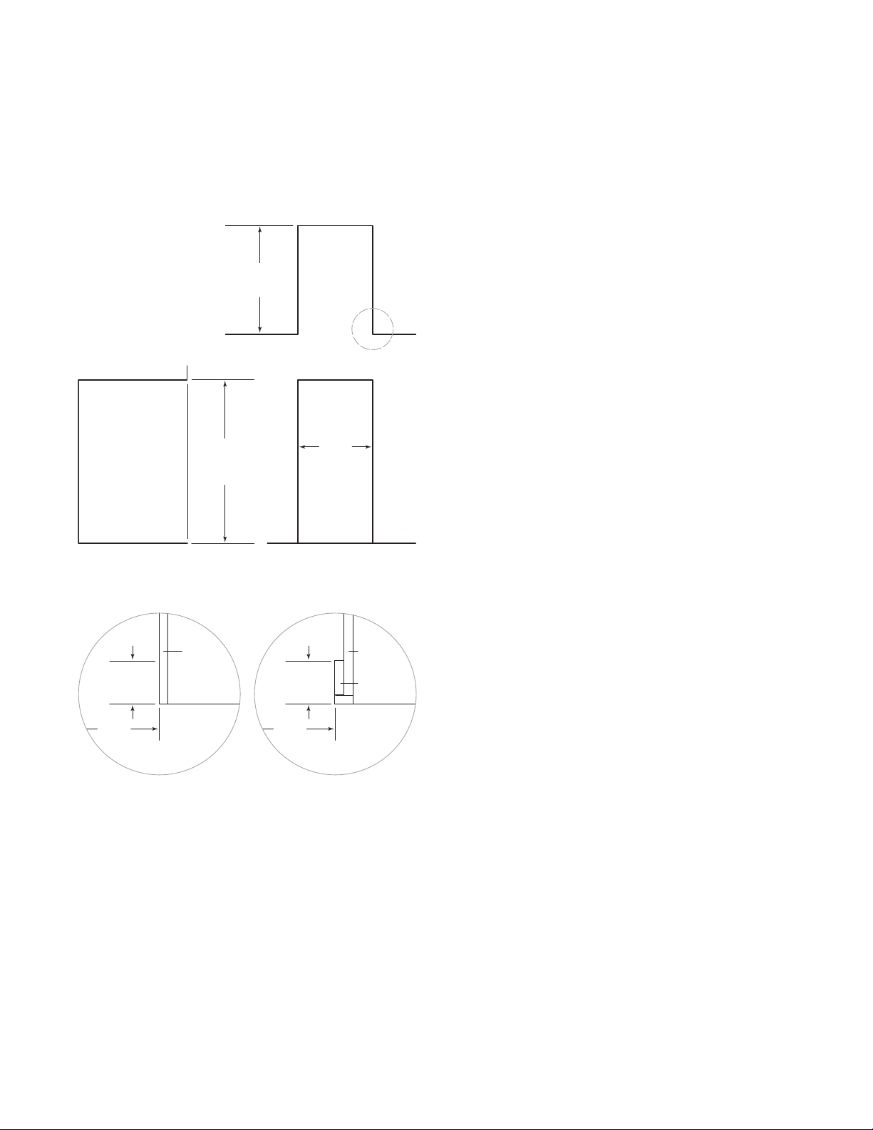
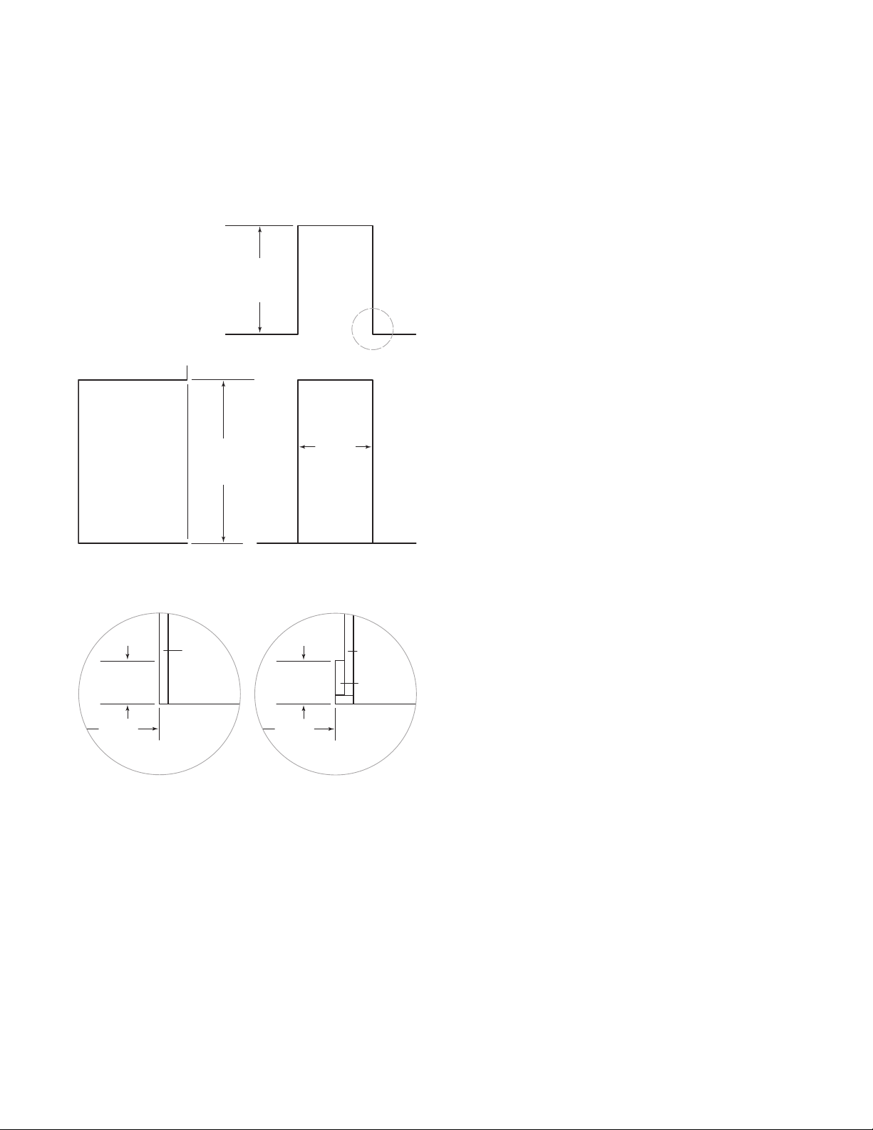
Opening Dimensions
ICE MAKER
24" (610)
OPENING
DEPTH
TOP VIEW
341/2"
(876)
OPENING
HEIGHT
SIDE VIEW FRONT VIEW
NOTE: 31/2" (89) finished returns will be visible and should be finished to match cabinetry
151/4"
(387)
OPENING
WIDTH
IMPORTANT NOTE:
It is recommended that the electrical
and water supply be placed in an adjacent cabinet. If they
are placed within the opening, additional cabinet depth may
be required.
31/2" (89)
FINISHED
RETURN
151/4"
(387)
FRAMELESS
CABINETRY
3
/4" (19)
TYPICAL
31/2" (89)
FINISHED
RETURN
151/4"
(387)
FRAMED
CABINETRY
3
/4" (19)
TYPICAL
FILLER
4 | Sub-Zero Customer Care 800.222.7820
Page 5
SITE PREPARATION
E
E
E
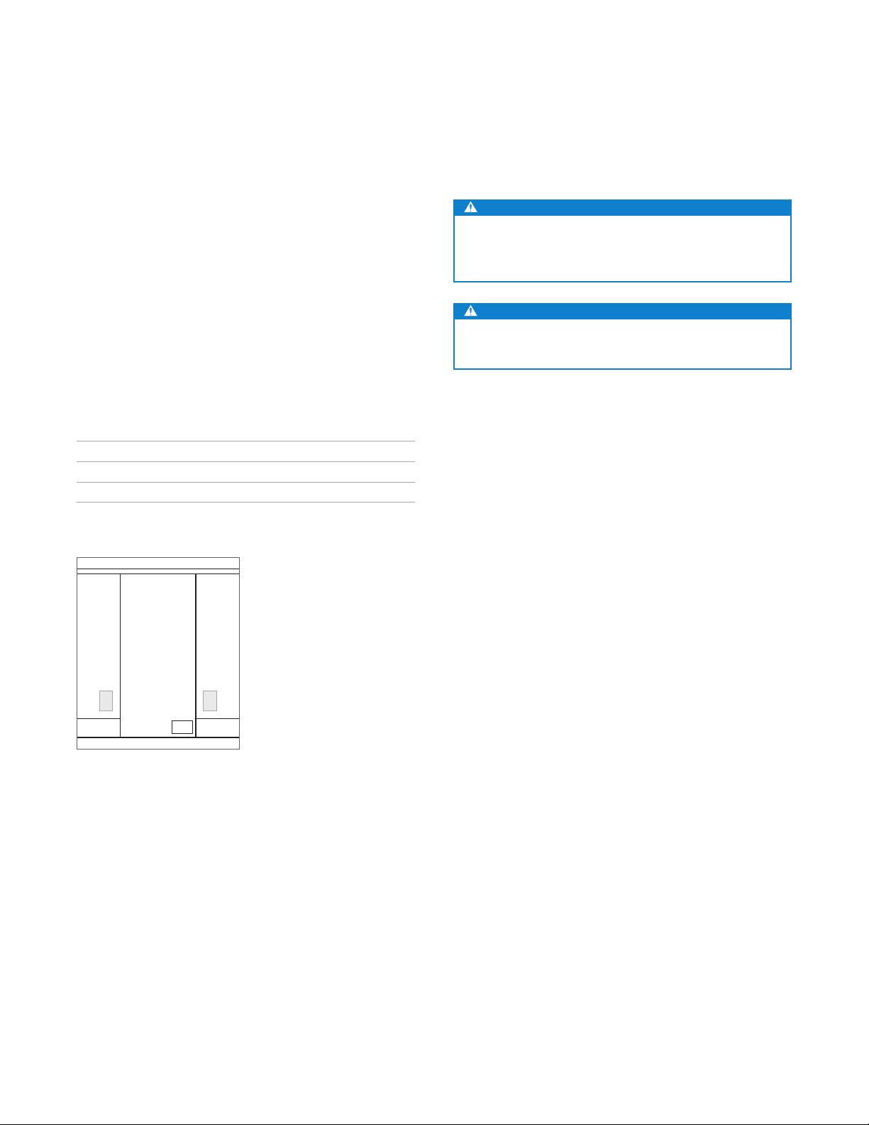
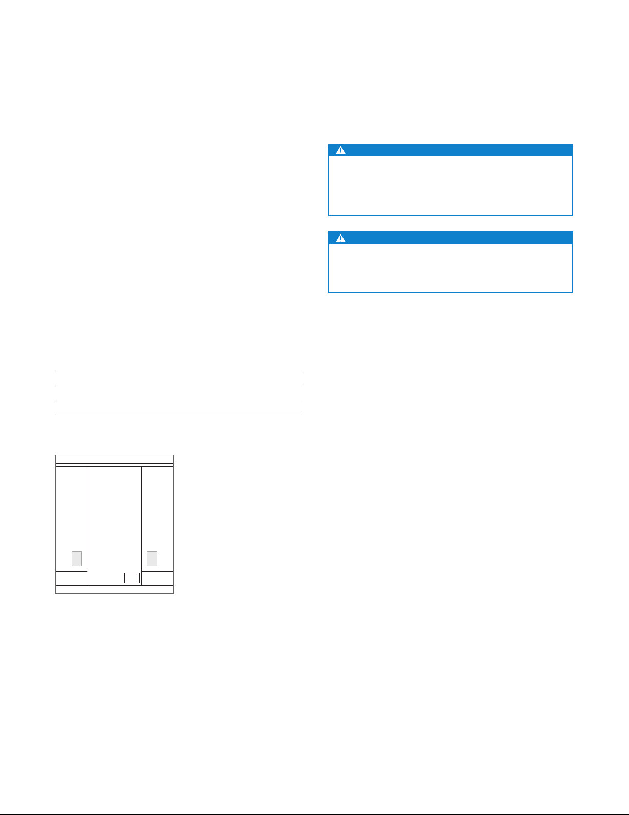
Electrical Requirements
Installation must comply with all applicable electrical codes.
Although it can be located anywhere on the back wall, it
is recommended that the electrical supply be placed in an
adjacent cabinet or in the lower right of the opening. Refer
to the illustration below. A separate circuit servicing only this
appliance is required.
Model UC-15I(P)O is designed and safe for use in outdoor
applications. When installed outdoors, a ground fault circuit
interrupter (GFCI) is required to reduce the risk of electrical
shock. A GFCI is not recommended for use with the indoor
model and may cause interruption of operation.
ELECTRICAL REQUIREMENTS
Electrical Supply 115 VAC, 60 Hz
Service 15 amp dedicated circuit
Receptacle 3-prong grounding-type
CAUTION
The outlet must be checked by a qualied electrician
to be sure it is wired with the correct polarity. Verify the
outlet is properly grounded.
WARNING
Do not use an extension cord, two-prong adapter, or
remove the power cord ground prong.
Electrical supply location
subzero.com | 5
Page 6
SITE PREPARATION
24" (610)
ROUGH
OPENING
DEPTH
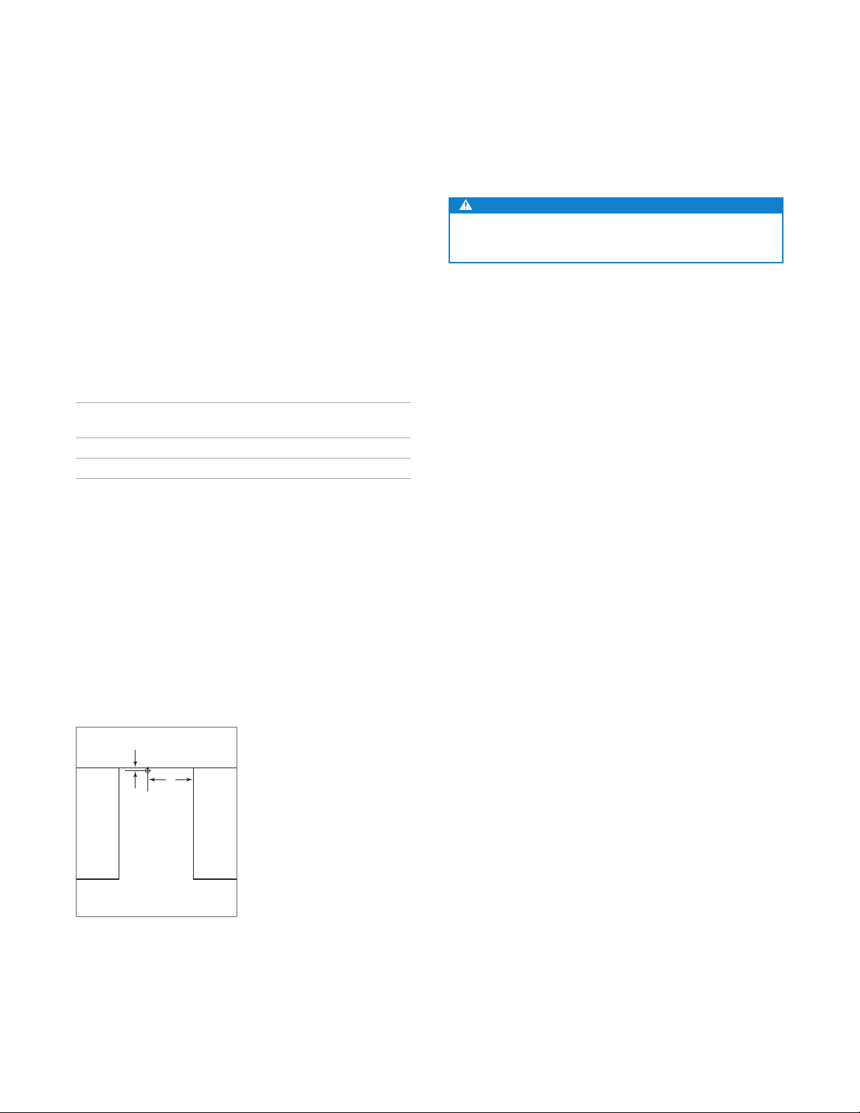
Plumbing Requirements
Installation must comply with all applicable plumbing codes.
The water supply line should be located as shown in the
illustration below. The water supply line should be connected to the house supply with an easily accessible shutoff valve. Do not use self-piercing valves.
A reverse osmosis system can be used provided there is
constant water pressure of 20–80 psi
the unit at all times. A copper line is not recommended for
this application.
PLUMBING REQUIREMENTS
Water Supply Line
Water Pressure 20–80 psi
Excess Water Line for Connection 36" (914)
ICE MAKER DRAIN
The ice maker can be ordered with or without a drain pump.
Models without a pump will drain water by gravity.
A drain must be installed.
(1.4–5.5 bar) supplied to
1
/4" OD copper, braided stain-
less steel, or PEX tubing
(1.4–5.5 bar)
Preparation
CAUTION
Before moving the unit into position, secure the door
closed and protect any nished ooring.
Uncrate the unit and inspect for damage. Remove the wood
base and discard shipping bolts and brackets. Remove and
recycle packing materials. Do not discard the kickplate and
hardware.
Use an appliance dolly to move the unit near the opening.
If the unit has been on its back or side, it must stand upright
for a minimum of 24 hours before connecting power.
The drain and inlet water tubes must be plumbed before
connection to the ice maker. For the gravity drain, horizontal
1
drain lines must have a
/4" (6) per 12" (305) fall. An air gap
will likely be required between the unit and drain. A stand
pipe with a trap below is acceptable for the drain.
8"
(203)
1
/2"
(13)
LOCATION OF
WATER LINE
TOP VIEW
Water supply location
6 | Sub-Zero Customer Care 800.222.7820
Page 7
INSTALLATION
Installation
INSTALL ICE MAKER
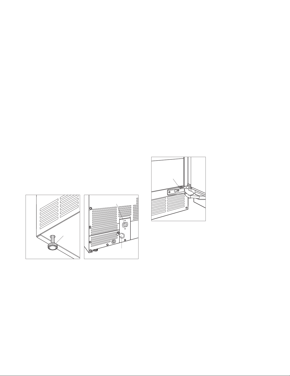
1 Adjust the leveling legs close to the desired height. Refer
to the illustration below.
2 Reverse the door swing if needed. Refer to steps out-
lined on page 9.
3 Gravity Drain Model: Install the drain hose provided onto
the drain tting on the back of unit and route to the open
site drain. Refer to the illustration below and plumbing
requirements on the previous page.
Drain Pump Model: Route the drain tubing through the
drain tting on the back of the unit and install the drain
hose provided on the drain pump. Route the other end of
the drain tubing to the drain site. Refer to the illustration
below and plumbing requirements on the previous page.
4 Use a compression tting to connect the water inlet on
the back of ice maker to the prepared
1
/4" (6) OD cold
water line. Refer to the illustration below.
DRAIN FITTING
5 Open the shut-off valve on the water line. Check all
plumbing connections for leaks. Failure to do so could
result in ooding.
6 Plug the power cord into the grounded receptacle.
7 Level the ice maker to assure the door closes and seals
properly. Place a level on the top of the unit and turn
each leveling leg to raise or lower as needed.
8 Move the ice maker into its nal position.
9 Anchor the ice maker by installing the two at head
screws provided through each hinge. Refer to the illustration below.
ANCHORING
SCREWS
Leveling
LEVELING
LEG
Drain connection
WATER INLET
Anchoring
subzero.com | 7
Page 8

INSTALLATION
Installation
VERIFY ICE PRODUCTION
1 Press “POWER” to turn the ice maker on.
2 Add one gallon (3.8 L) of cold water to the ice bin. Verify
the water completely drains from the ice bin and there
are no leaks. If the water has not drained within 60 seconds, there may be a kink in the drain tube or the drain
installation is incorrect.
3 Press “CLEAN”. Wait three minutes until the CLEAN light
ashes, then add 1 tablespoon
(15 ml) of undiluted ice
maker sanitizer directly into the spray area. Refer to the
illustration below. Use only the sanitizer made for the
Sub-Zero ice maker available at subzerowolfstore.com.
For questions, contact Sub-Zero Customer Care at
800-222-7820.
4 A 10-minute sanitizing cycle begins, followed by eight
rinse cycles. When the process is complete, the CLEAN
light will no longer be illuminated. The entire cycle takes
approximately 30 minutes.
5 At initial start-up, the ice maker will need approximately
30 minutes to freeze ice cubes and up to ve minutes to
harvest. Verify completion of the rst cycle ice production to conrm proper installation.
WATER
SHUTTERS
Water shutters location
8 | Sub-Zero Customer Care 800.222.7820
Page 9
INSTALLATION
Installation
REVERSE DOOR SWING
The door hinges are designed to be placed on either the
right or left side of the ice maker. The unit is shipped with
the door hinged on the right. Moving the hinges to the left
using the pre-drilled holes allows for a left-hand door swing.
To Reverse the Door Swing:
1 Detach the hinges from the ice maker by removing two
screws per hinge, then remove the door. Remove the
shim located between the cabinet and bottom hinge, this
shim will transfer to the left side bottom hinge.
2 Detach the hinges from the door by removing two
screws per hinge.
3 Detach the right-hand upper trim (shaded area) from the
door by removing the two screws. Refer to the illustration below. Replace it with the left-hand upper trim.
4 Transfer the hinges to the left side of the door and
reinstall. The upper hinge will now be in the lower hinge
position and the lower hinge in the upper hinge position.
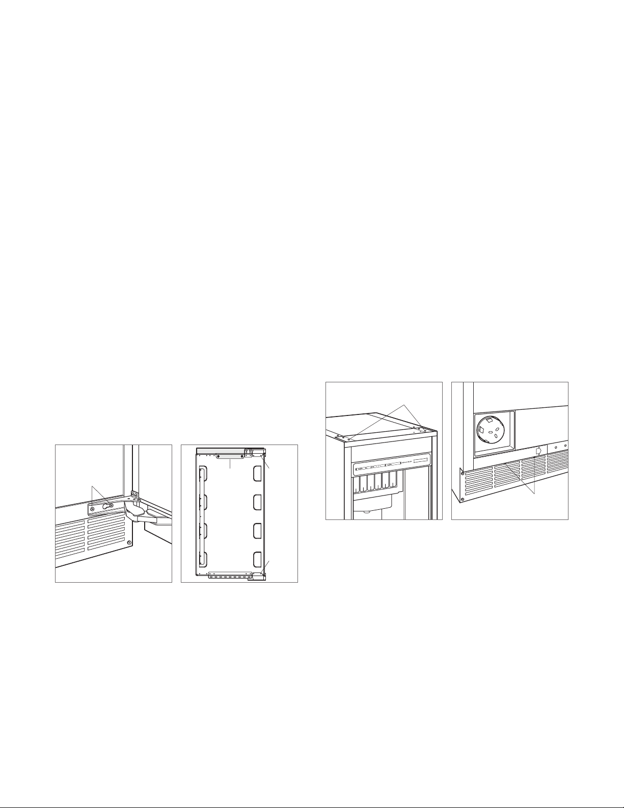
5 Remove the top cover of the ice maker by removing the
two screws at the top rear of the unit.
6 Remove the four screws from the front top rail, then pivot
the top rail end for end to expose the two left-hand top
hinge mounting holes and reinstall. Refer to the illustration below.
7 Remove the two screws from the lower edge of the
bottom trim plate and slide it to the right to cover
the right hinge mounting holes. Refer to the illustration below. The left hinge mounting holes will now be
exposed.
8 Reinstall the shim removed in step 1, between the
cabinet and the left side bottom hinge. Reinstall the door
by mounting the hinges using the left hinge mounting
holes. Verify operation of the door.
TOP RAIL
SCREWS
HINGE
SCREWS
Remove door
UPPER
TRIM (RH)
Detach hinges and trim
HINGE
HINGE
Front top rail
Bottom trim plate
TRIM PLATE
SCREWS
subzero.com | 9
Page 10
INSTALLATION
Custom Panel
OVERLAY PANEL
For overlay applications, a custom door panel must be
installed. The panel size is critical for a proper t. To verify
panel requirements and dimensions, refer to the Sub-Zero
Design Guide at subzero.com/specs.
Finish all sides of the custom panel. They will be visible
when the door is open.
A D-style handle is recommended. The door handle must be
located near the edge of the panel opposite the hinge, centered top to bottom. Stainless steel tubular and pro handles
are avail able through an authorized Sub-Zero dealer. For
local dealer information, visit the nd a showroom section
of our website, subzero.com.
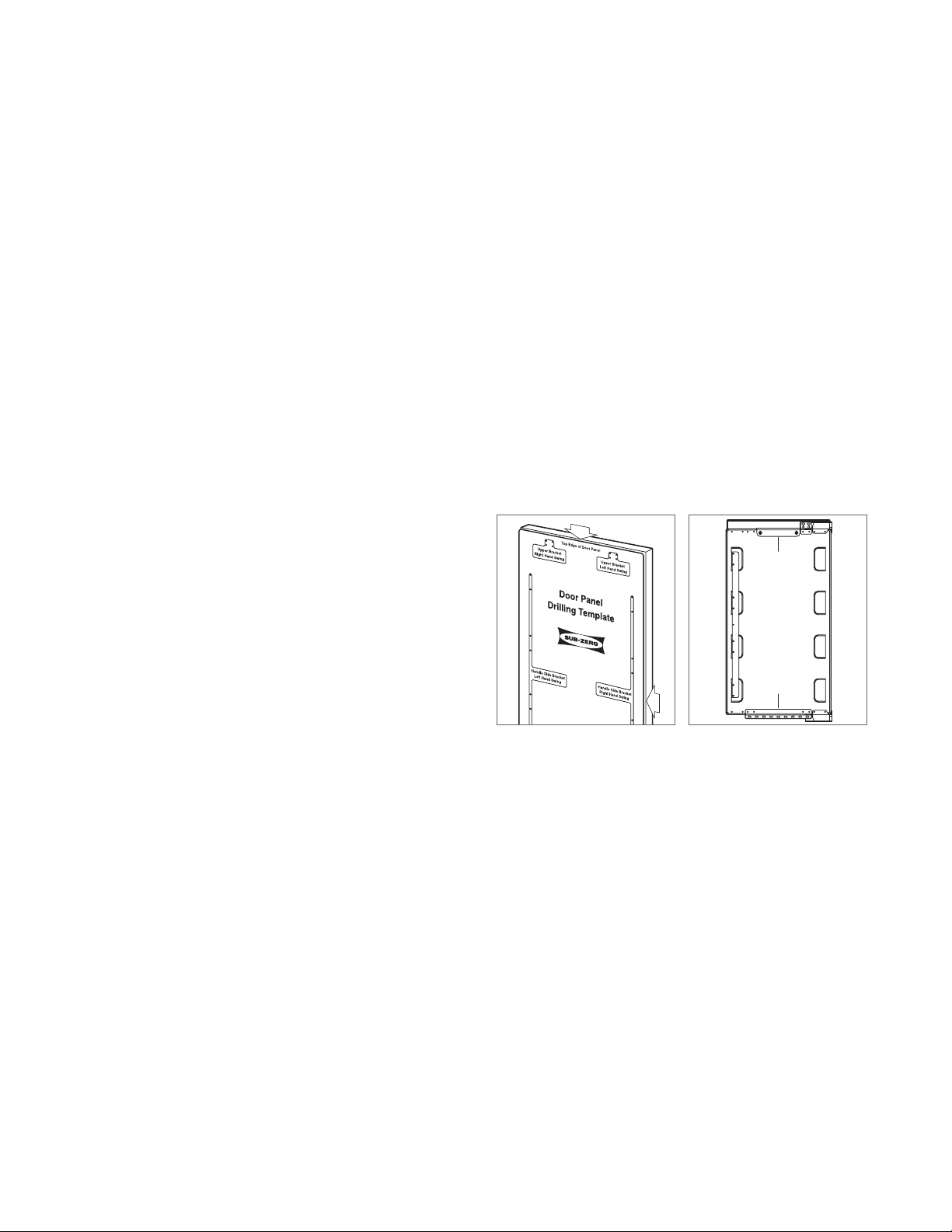
PANEL INSTALLATION
Remove the handle side bracket attached to the front of
the door. Place the custom door panel face down on a
protected work surface. Place the template on the back of
the door panel, then mark and drill the holes. Secure the
1
mounting bracket to the panel with the #8 x
/2" screws
provided. Refer to the illustration below.
Install the door panel by engaging the tabbed bracket to
the door. Once the door panel is in place, use the remaining
1
/2" screws to secure the panel to the upper and lower
#8 x
mounting brackets. Once secure, install the hinge covers.
Refer to page 11.
UPPER
BRACKET
Template position
LOWER
BRACKET
Mounting brackets
10 | Sub-Zero Customer Care 800.222.7820
Page 11

INSTALLATION
Completion
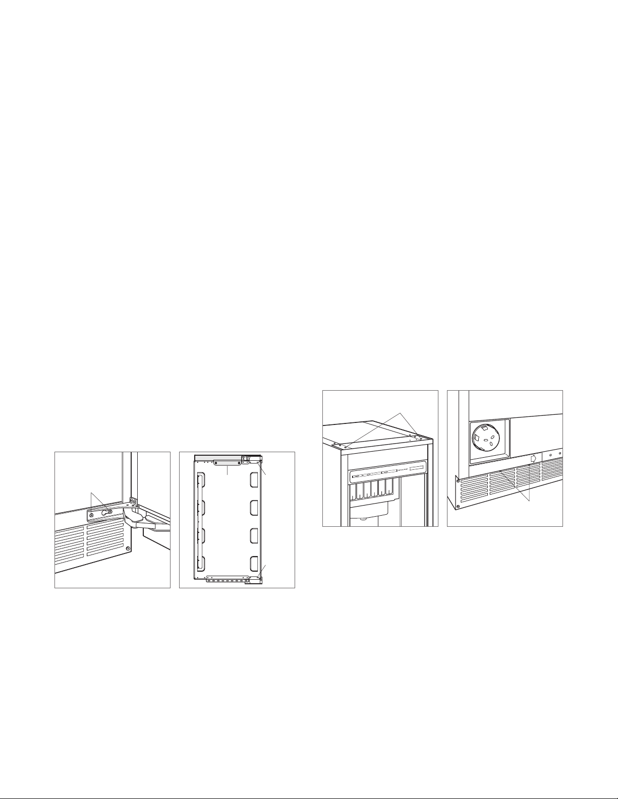
KICKPLATE INSTALLATION
Install the kickplate using the two screws provided. Refer to
the illustration below. The kickplate must be removable
for service. The oor cannot interfere with removal. Do not
cover the louvered section of the kickplate.
90° DOOR STOP
The door stop pins provided with the ice maker will limit the
door swing to 90°.
To install, open the door to approximately 80°. Insert one
stop pin into the top door hinge (pin enters from the bottom)
and the other stop pin into the bottom door hinge (pin
enters from the top). Refer to the illustration below. Check
for proper operation.
DOOR STOP PIN
HINGE COVERS
Install the hinge covers once installation of the ice maker
is complete and the door stop pins have been installed
(if applicable). The knock-out in the hinge cover must be
removed if the 90° door stop is used.
Verify the hinges are free of dirt or grease before applying
the covers. To install, remove paper backing and apply the
hinge covers to each hinge. Attach the magnetic center
covers. Refer to the illustration below.
WARNING
Follow all city and state laws when storing, recycling,
or discarding unused refrigerators and freezers.
KNOCK-OUT
90° door stop
Sub-Zero, Sub-Zero & Design, Sub-Zero & Snowake Design, Dual Refrigeration, The Living Kitchen, Great American Kitchens The Fine Art of Kitchen Design, Wolf, Wolf &
Design, Wolf Gourmet, W & Design, red colored knobs, Cove, and Cove & Design are registered trademarks and service marks of Sub-Zero Group, Inc. and its subsidiaries.
All other trademarks are property of their respective owners in the United States and other countries.
Hinge covers
subzero.com | 11
Page 12

FABRICADOR DE HIELO EMPOTRADA
Contenido
3 Fabricador de hielo empotrada
4 Dimensiones de la abertura
5 Instalación eléctrica
6 Instalación de plomería
7 Instalación
10 Panel personalizado
11 Finalización
Las características y especicaciones están sujetas a
cambios sin previo aviso. Visite subzero.com/specs para
obtener la información más actualizada.
Aviso importante
Para garantizar que este producto se instale y opere de
la forma más segura y eciente posible, tome nota de los
siguientes tipos de información resaltada en esta guía:
AVISO IMPORTANTE señala la información que es especial-
mente importante.
PRECAUCIÓN indica una situación en la que se pueden
sufrir heridas leves o provocar daños al producto si no se
siguen las instrucciones.
ADVERTENCIA indica peligro de que se produzcan heridas
graves o incluso la muerte si no se siguen las precauciones.
AVISO IMPORTANTE: en toda esta guía, las dimensiones
entre paréntesis son milímetros, a menos que se especique lo contrario.
AVISO IMPORTANTE: guarde estas instrucciones para el
inspector eléctrico local.
2 | Atención al cliente de Sub-Zero 800.222.7820
Page 13

FABRICADOR DE HIELO EMPOTRADA
Información del producto
La información importante del producto, incluido el modelo
y número de serie de la unidad, se encuentra en la placa
de datos del producto. La placa de datos se encuentra en
la esquina superior izquierda del recipiente de almacenamiento de hielo, en la parte posterior de la unidad. Consulte
la siguiente ilustración.
Si necesita servicio, póngase en contacto con el centro
de servicio autorizado de Sub-Zero y tenga a la mano el
modelo y número de serie de la máquina. Para obtener
los datos del centro de servicio autorizado de Sub-Zero
más cercano o si tiene preguntas acerca de la instalación,
visite la sección de Soporte y Servicio de nuestro sitio web,
subzero.com o llame a la línea de atención al cliente de
Sub-Zero al 800-222-7820.
Herramientas | Materiales
• Destornilladores: estándar, Phillips y Torx.
• Taladro eléctrico.
• Juego de llaves de cubo e inglesas estándar.
• Nivel de 2'.
• Cortador de tubos.
(.9 m) de tubería de cobre, trenzada de acero inoxi-
• 3'
dable o PEX de
• Válvula de asiento.
• Material para proteger la casa, el piso y los gabinetes
durante la instalación.
1
/4" de diámetro exterior.
PLACA DE
DATOS
Ubicación de la placa de datos
subzero.com | 3
Page 14

PREPARACIÓN DEL SITIO
Dimensiones de abertura
FABRICADOR DE HIELO
(610)
24"
PROFUNDIDAD
DE LA
ABERTURA
VISTA SUPERIOR
341/2"
(876)
ALTURA DE
LA ABERTURA
VISTA LATERAL VISTA FRONTAL
NOTA: Los tubos de retorno de 31/2" (89) con acabados se podrán ver y se deben
terminar para que se ajusten a los gabinetes.
151/4"
(387)
ANCHURA DE
ABERTURA
AVISO IMPORTANTE:
Se recomienda que el suministro
eléctrico y de agua se encuentren en un gabinete adyacente. Si se encuentra dentro de la abertura, posiblemente
el gabinete deba ser más profundo.
TUBO DE
RETORNO DE
31/2" (89) CON
ACABADOS
151/4"
(387)
GABINETE SIN
MARCO
TÍPICO
3
DE
/4" (19)
TUBO DE
RETORNO DE
31/2" (89) CON
ACABADOS
151/4"
(387)
GABINETE CON
MARCO
TÍPICO
3
/4" (19)
DE
RELLENO
4 | Atención al cliente de Sub-Zero 800.222.7820
Page 15

PREPARACIÓN DEL SITIO
E
E
E
Instalación eléctrica
La instalación debe cumplir con todos los códigos eléctricos vigentes.
Aunque puede estar ubicado en cualquier lugar de la pared
posterior, se recomienda instalar el suministro eléctrico en
un gabinete adyacente o en la esquina inferior derecha de
la abertura. Consulte la siguiente ilustración. Se necesita un
circuito independiente que le suministre electricidad únicamente a este electrodoméstico.
El Modelo UC-15I(P)O está diseñado y es seguro para su
uso en aplicaciones al aire libre. Cuando se instala al aire
libre, es necesario instalar un circuito de fallos de conexión
a tierra (GFCI, por sus siglas en inglés) para reducir el riesgo
de descarga eléctrica. No es recomendable usar un GFCI
con el modelo interior, ya que puede interrumpir el funcionamiento de la unidad.
REQUISITOS ELÉCTRICOS
Suministro eléctrico 115 V CA, 60 Hz
Servicio Circuito dedicado de 15 amperes
Receptáculo Conexión a tierra de 3 clavijas
PRECAUCIÓN
Un electricista calicado debe revisar el tomacorriente
para asegurarse de que la conexión se haya realizado
con la polaridad correcta. Verique que el tomacorriente esté debidamente conectado a tierra.
ADVERTENCIA
No use un cable de extensión, adaptador de dos clavijas ni retire la clavija con conexión a tierra del cable
de corriente.
Ubicación del suministro
eléctrico
subzero.com | 5
Page 16

PREPARACIÓN DEL SITIO
24" (610)
ROUGH
OPENING
DEPTH
Plomería
La instalación debe cumplir con todos los códigos de plomería vigentes.
La tubería del suministro de agua debe colocarse como se
muestra en la siguiente ilustración. La tubería del suministro de agua debe conectarse al suministro doméstico
con una válvula de cierre de fácil acceso. No use válvulas
autoperforantes.
Se puede usar un sistema de ósmosis inversa siempre
y cuando la presión del agua que llegue a la unidad se
mantenga de forma constante entre 20 a 80 psi
5.5bares)
en todo momento. No es recomendable usar tube-
rías de cobre para esta aplicación.
REQUISITOS DE PLOMERÍA
Tuberías de suministro
de agua
Presión del agua De 20 a 80 psi
Tubería de exceso de
agua para la conexión
Tubería de cobre, trenzada de acero inoxi-
dable o PEX de 1/4" de diámetro exterior
(de 1.4 a
(de 1.4 a 5.5 bares)
36" (914)
Preparación
PRECAUCIÓN
Antes de mover la unidad a su posición, verique que
la puerta esté cerrada y proteja el suelo con acabado.
Desembale la unidad e inspeccione si tiene algún daño.
Retire la base de madera y deseche los pernos y soportes
de transporte. Retire y recicle los materiales de embalaje.
No deseche el zócalo ni las piezas de montaje.
Use una plataforma rodante para mover la unidad cerca de
la abertura.
Si la unidad ha estado o está acostada o de lado, debe
ponerla de pie y dejarla así durante un mínimo de 24 horas
antes de conectarla al suministro eléctrico.
DRENAJE DE LA FABRICADOR DE HIELO
Puede ordenar la fabricador de hielo con o sin una bomba
de drenaje. Los modelos sin bomba drenarán el agua por
gravedad. Se debe instalar un drenaje.
Los tubos de agua de entrada y drenaje deben instalarse
antes de conectarlos a la fabricador de hielo. Para el drenaje
por gravedad, las tuberías de drenaje horizontales deben
1
tener una caída de
/4" (6) cada 12" (305). Es probable que
se requiera un entrehierro entre la máquina y el drenaje. Se
puede utilizar un tubo vertical con un colector abajo para el
drenaje.
8"
(203)
1
/2"
(13)
UBICACIÓN DE
LA LÍNEA
DE AGUA
VISTA SUPERIOR
Ubicación del suministro de agua
6 | Atención al cliente de Sub-Zero 800.222.7820
Page 17

INSTALACIÓN
Instalación
INSTALE LA FABRICADOR DE HIELO
1 Ajuste las patas niveladoras cerca de la altura deseada.
Consulte la siguiente ilustración.
2 Si es necesario, invierta el giro de la puerta. Consulte los
pasos indicados en la página 9.
3 Modelo de drenaje por gravedad: Instale la manguera
de drenaje provista en el accesorio de drenaje ubicado
en la parte posterior de la unidad y guíela hacia el drenaje abierto. Consulte la ilustración a continuación y los
requisitos de plomería en la página anterior.
Modelo de bomba de drenaje: Guíe los tubos de
drenaje a través del accesorio de drenaje en la parte
posterior de la unidad e instale la manguera de drenaje
provista en la bomba de drenaje. Guíe el otro extremo de
los tubos de drenaje hacia el lugar de drenaje. Consulte
la ilustración a continuación y los requisitos de plomería
en la página anterior.
4 Use un accesorio de compresión para conectar la
entrada de agua en la parte posterior de la fabricador
1
de hielo a la tubería de agua fría de
/4" (6) de diámetro
exterior. Consulte la siguiente ilustración.
5 Abra la llave de paso en la tubería de agua. Revise
todas las conexiones de plomería para comprobar que
no haya fugas. Si no lo hace, se puede ocasionar una
inundación.
6 Enchufe el cable de corriente eléctrica en un tomaco-
rriente con conexión a tierra.
7 Nivele la fabricador de hielo para asegurar que la puerta
se cierre y selle correctamente. Coloque un nivel en la
parte superior de la unidad y gire cada pata niveladora
para levantarla o bajarla, según sea necesario.
8 Mueva la fabricador de hielo a su posición nal.
9 Ancle la fabricador de hielo mediante la instalación de
los dos tornillos de cabeza plana provistos a través de
cada bisagra. Consulte la siguiente ilustración.
TORNILLOS
DE ANCLAJE
Nivelación
PATA
NIVELADORA
ACCESORIO DE DRENAJE
ENTRADA DE AGUA
Conexión de drenaje
Anclaje
subzero.com | 7
Page 18

INSTALACIÓN
Instalación
VERIFIQUE LA PRODUCCIÓN DE HIELO
1 Presione “POWER” (Potencia) para encender la fabri-
cador de hielo.
2 Agregue un galón (3.8 l) de agua fría al recipiente de
hielo. Verique que el agua se drene completamente del
recipiente de hielo y que no haya fugas. Si el agua no se
ha drenado dentro de 60 segundos, el tubo de drenaje
puede estar doblado o el drenaje puede estar instalado
incorrectamente.
3 Presione “CLEAN” (Limpiar). Espere tres minutos hasta
que la luz CLEAN parpadee, luego, agregue 1 cucha-
(15 ml) de desinfectante para generadores de hielo
rada
sin diluir directamente en la zona de rocío. Consulte la
siguiente ilustración. Solo use un desinfectante elaborado para la
fabricador de hielo Sub-Zero disponible en
subzerowolfstore.com. Si tiene alguna pregunta, comuníquese con la línea de atención al cliente de Sub-Zero
al 800-222-7820.
4 Comienza un ciclo de desinfección de 10 minutos,
seguido de ocho ciclos de enjuague. Una vez que el proceso haya nalizado, la luz CLEAN dejará de estar iluminada. Todo el ciclo dura aproximadamente 30minutos.
5 En la puesta en marcha inicial, la fabricador de hielo
necesitará aproximadamente 30 minutos para congelar
los cubos de hielo y hasta cinco minutos para recogerlos. Verique la nalización de la producción de hielo
del primer ciclo para conrmar que la instalación esté
correcta.
OBTURADORES
DE AGUA
Ubicación de los obturadores
de agua
8 | Atención al cliente de Sub-Zero 800.222.7820
Page 19
INSTALACIÓN
Instalación
INVIERTA EL GIRO DE LA PUERTA
Las bisagras de la puerta están diseñadas para colocarse
en el lado derecho o izquierdo de la fabricador de hielo. La
máquina se envía con la bisagra de la puerta a la derecha.
Si mueve las bisagras a la izquierda en los oricios previamente perforados, podrá girar la puerta a la izquierda.
Para invertir el giro de la puerta:
1 Retire las bisagras de la fabricador de hielo sacando dos
tornillos por bisagra, luego quite la puerta. Retire la cuña
ubicada entre el gabinete y la bisagra inferior; esta cuña
se cambiará a la bisagra inferior izquierda.
2 Retire las bisagras de la puerta sacando dos tornillos por
bisagra.
3 Quite el ribete superior derecho (área sombreada) de
la puerta sacando dos tornillos. Consulte la siguiente
ilustración. Reemplácelo con el ribete superior izquierdo.
4 Cambie las bisagras al lado izquierdo de la puerta y
vuelva a instalarlas. Ahora la bisagra superior estará en
la posición de la bisagra inferior y viceversa.
5 Quite la tapa superior de la fabricador de hielo sacando
dos tornillos de la parte posterior de la unidad.
6 Quite cuatro tornillos del riel superior delantero, luego
gire el extremo del riel superior para exponer los dos
oricios de montaje de la bisagra superior izquierda y
vuelva a instalar. Consulte la siguiente ilustración.
7 Quite dos tornillos del borde inferior de la placa de la
placa decorativa inferior y deslícela hacia la derecha
para tapar los oricios de montaje de la bisagra derecha.
Consulte la siguiente ilustración. Ahora los oricios de
montaje de la bisagra izquierda estarán expuestos.
8 Vuelva a instalar la cuña que retiró en el paso 1, entre el
gabinete y la bisagra inferior del lado izquierdo. Vuelva a
instalar la puerta colocando las bisagras en los oricios
de montaje de la bisagra izquierda. Verique que la
puerta funcione.
TORNILLOS DEL
RIEL SUPERIOR
TORNILLOS DE
LA BISAGRA
Retire la puerta
RIBETE
SUPERIOR
(RH)
BISAGRA
BISAGRA
Retire las bisagras y el ribete
Riel superior delantero
TORNILLOS DE LA
PLACA DECORATIVA
Placa del ribete inferior
subzero.com | 9
Page 20

INSTALACIÓN
Panel personalizado
PANEL REVESTIBLE
Para aplicaciones revestibles, es necesario instalar un panel
de puerta personalizado. El tamaño del panel es fundamental para un buen ajuste. Para vericar los requisitos y
dimensiones del panel, consulte la guía de diseño de SubZero en subzero.com/specs.
Aplique el acabado a todos los lados de los paneles personalizados. Estos serán visibles con la puerta abierta.
Se recomienda usar manijas estilo D. Las manijas de las
puertas deben colocarse cerca del borde del panel opuesto
a la bisagra, centradas entre los extremos superior e inferior.
Están disponibles manijas tubulares y pro de acero inoxidable con los distribuidores autorizados Sub-Zero. Para
obtener más información de los distribuidores locales, visite
la sección para encontrar una sala de exhibición de nuestro
sitio web, subzero.com.
INSTALACIÓN DEL PANEL
Retire el soporte del lado de la manija unido a la parte
delantera de la puerta. Coloque el panel de puerta revestible
personalizado boca abajo sobre una supercie de trabajo
protegida. Coloque la plantilla en la parte posterior del panel
de la puerta, luego marque y taladre agujeros. Asegure el
1
soporte de montaje al panel con los tornillos # 8 x
/2" sumi-
nistrados. Consulte la siguiente ilustración.
Instale el panel de la puerta acoplando el soporte con
pestañas a la puerta. Una vez que el panel de la puerta está
1
en su lugar, utilice los tornillos # 8 x
/2" restantes para asegurar el panel a los soportes de montaje superior e inferior.
Una vez seguro, instale las cubiertas de la bisagra. Consulte
la página 11.
SOPORTE
SUPERIOR
Posición de la plantilla
SOPORTE
INFERIOR
Soportes de montaje
10 | Atención al cliente de Sub-Zero 800.222.7820
Page 21

INSTALACIÓN
Finalización
INSTALACIÓN DEL ZÓCALO
Instale el zócalo con los dos tornillos proporcionados. Consulte la siguiente ilustración. El zócalo debe ser desmontable para sacarlo cuando sea necesario hacerle servicio a
la máquina. El suelo no debe interferir al desmontarlo. No
cubra la sección tipo persiana del zócalo.
TOPE PARA PUERTA A 90°
Los pasadores del tope de la puerta proporcionados con
la fabricador de hielo limitarán el giro de la puerta a 90°.
Para instalar, abra la puerta a aproximadamente 80°. Inserte
un pasador del tope en la bisagra de la puerta superior
(el pasador entra desde la parte inferior) y el otro pasador
de tope en la bisagra de la puerta inferior (el pasador entra
desde la parte superior). Consulte la siguiente ilustración.
Compruebe que funcione correctamente.
PASADOR DEL TOPE
DE LA PUERTA
TAPAS DE LAS BISAGRAS
Instale las tapas de las bisagras una vez que haya nalizado
la instalación de la fabricador de hielo y se hayan instalado
los pasadores del tope de la puerta (si corresponde). El
prepunzonado en la tapa de la bisagra se debe eliminar si
se usa el tope de puerta de 90°.
Verique que las bisagras no estén sucias ni tengan grasa
antes de colocar las tapas. Para instalar, quite el papel
protector y coloque las tapas de las bisagras en cada una
de ellas. Instale las tapas del centro magnético. Consulte la
siguiente ilustración.
ADVERTENCIA
Siga todas las leyes estatales y locales para almacenar,
reciclar o desechar los refrigeradores y congeladores
no utilizados.
PREPUNZONADO
Tope para puerta a 90°
Sub-Zero, Sub-Zero & Design, Sub-Zero & Snowake Design, Dual Refrigeration, The Living Kitchen, Great American Kitchens The Fine Art of Kitchen Design, Wolf, Wolf &
Design, Wolf Gourmet, W & Design, red colored knobs, Cove, and Cove & Design son marcas registradas y marcas de servicio de Sub-Zero Group, Inc. y sus asociados. Todas
las demás marcas registradas son propiedad de sus dueños respectivos en los Estados Unidos y otros países.
Tapas de las bisagras
subzero.com | 11
Page 22

MACHINE À GLAÇONS SOUS LE COMPTOIR
Table des matières
3 Machine à glaçons sous le comptoir
4 Dimensions de l'ouverture
5 Électricité
6 Plomberie
7 Installation
10 Panneau personnalisé
11 Achèvement
Les caractéristiques et les spécications peuvent
être modiées en tout temps sans préavis.
Visitez subzero.com/specs pour obtenir les
renseignements les plus récents.
Remarque importante
Pour s'assurer que ce produit est installé et utilisé en toute
sécurité et aussi efcacement que possible, prenez note
des types de renseignement mis en évidence tout au long
de ce guide :
REMARQUE IMPORTANTE met en évidence des
renseignements qui sont particulièrement importants.
MISE EN GARDE indique une situation où une blessure
mineure ou des dommages au produit peuvent se produire
si les directives ne sont pas respectées.
AVERTISSEMENT décrit un danger qui peut causer une
blessure grave ou la mort si les précautions ne sont pas
respectées.
REMARQUE IMPORTANTE : tout au long de ce guide, les
dimensions entre parenthèses sont en millimètres à moins
d'indication contraire.
REMARQUE IMPORTANTE : conservez ces directives pour
l'inspecteur en électricité local.
2 | Service à la clientèle de Sub-Zero 800.222.7820
Page 23
MACHINE À GLAÇONS SOUS LE COMPTOIR
Renseignements sur le produit
Des renseignements importants sur le produit, y compris les
numéros de modèle et de série, se trouvent sur la plaque
signalétique du produit. La plaque signalétique est située
dans le coin supérieur gauche du bac de rangement, à
l'arrière de l'unité. Reportez-vous à l'illustration ci-dessous.
Si vous avez besoin de service, communiquez avec le
service Sub-Zero certié par l'usine avec les numéros de
modèle et de série. Pour obtenir le nom du centre de service
Sub-Zero certié par l'usine le plus près de chez vous ou si
vous avez des questions concernant l'installation, visitez la
section Support et service de notre site Web, subzero.com
ou appelez le service à la clientèle de Sub-Zero au
800-222-7820.
Outils | matériaux
• Tournevis—standard, cruciforme et Torx.
• Perceuse électrique.
• Ensemble de clés et de douilles standard.
• Niveau de 2 pi.
• Coupe-tube.
(0,9m) de tube PEX ou en acier inoxydable tressé en
• 3pi
cuivre de ¼po de diamètre extérieur.
• Vanne à étrier.
• Des matériaux pour protéger la résidence, le plancher et
les armoires pendant l'installation.
PLAQUE
SIGNALÉTIQUE
Emplacement de la plaque
signalétique
subzero.com | 3
Page 24
PRÉPARATION DU SITE
Dimensions de l'ouverture
MACHINE À GLAÇONS
po (610)
24
PROFONDEUR
DE
D’OUVERTURE
VUE DE DESSUS
341/2 po
(876)
HAUTEUR DE
D’OUVERTURE
VUE DE PROFIL VUE DE FACE
REMARQUE : Les retours finis de 31/2 po (89) seront visibles et doivent être finis pour
s’apparier aux armoires.
151/4 po
(387)
LARGEUR DE
L’OUVERTURE
REMARQUE IMPORTANTE :
il est recommandé que
l'alimentation électrique et l'alimentation en eau soient
placées dans une armoire adjacente. Si elles sont placées
dans la même ouverture, la profondeur de l'armoire pourra
devoir être augmentée.
RETOUR
FINI DE
31/2 po (89)
151/4 po
(387)
ARMOIRE SANS
CADRE
TYPIQUE
DE
3
/4 po (19)
RETOUR
FINI DE
31/2 po (89)
151/4 po
(387)
ARMOIRE AVEC
CADRE
TYPIQUE
DE
3
/4 po (19)
MATÉRIAU DE
REMBLAYAGE
4 | Service à la clientèle de Sub-Zero 800.222.7820
Page 25
PRÉPARATION DU SITE
E
E
E
Électricité
L'installation doit se conformer à tous les codes électriques
applicables.
Bien qu'elle puisse être située n'importe où sur le mur
arrière, il est recommandé que l’alimentation électrique
soit placée dans une armoire adjacente ou dans le coin
inférieur droit de l'ouverture. Reportez-vous à l'illustration
ci-dessous. Un circuit séparé servant uniquement cet
appareil est requis.
Le modèle UC-15I(P)O est conçu pour être utilisé sans
danger dans les applications extérieures. Lors d'une
installation à l'extérieur, un disjoncteur de fuite de terre
(GFCI) est requis pour réduire le risque de choc électrique.
Un disjoncteur de fuite de terre n'est pas recommandé pour
usage avec le modèle pour l’intérieur et peut interrompre le
fonctionnement.
EXIGENCES ÉLECTRIQUES
Alimentation électrique 115 volts CA, 60 Hz
Service Circuito dedicado de 15 amperes
Prise mise à la terre à trois broches
MISE EN GARDE
Cette prise doit être vériée par un électricien qualié
pour s'assurer qu'elle est câblée avec la polarité
appropriée. Assurez-vous que la prise est correctement
mise à la terre.
AVERTISSEMENT
N'utilisez pas une rallonge ou un adaptateur à deux
broches et ne retirez pas la broche de mise à la terre
du cordon d'alimentation.
Emplacement de l'alimentation
électrique
subzero.com | 5
Page 26

PRÉPARATION DU SITE
24" (610)
ROUGH
OPENING
DEPTH
Plomberie
L'installation doit se conformer à tous les codes de
plomberie applicables.
La conduite d'alimentation en eau doit se trouver à
l'endroit indiqué dans l'illustration ci-dessous. La conduite
d'alimentation en eau doit être reliée à l'alimentation de
la maison avec un robinet d'arrêt facilement accessible.
N'utilisez pas des vannes à auto-perçage.
Un système à osmose inverse peut être utilisé à condition
qu'il y ait une pression d'eau constante de 20 à 80lb/po²
(1,4 à 5,5bars)
cuivre n'est pas recommandée pour cette application.
EXIGENCES DE PLOMBERIE
Conduite d'alimentation
en eau
Pression d'eau 20–80 lb/po²
Conduite d'alimentation en eau
supplémentaire pour connexion
ÉVACUATION DE LA MACHINE À GLAÇONS
vers l'unité en tout temps. Une conduite en
tube PEX ou en acier inoxydable tressé
en cuivre de ¼po (6) de diamètre extérieur
(1,4–5,5 bars)
36po (914)
Préparation
MISE EN GARDE
Avant de mettre l'unité en place, sécurisez la porte en
position fermée et protégez tout plancher ni.
Sortez l'unité de la boîte et examinez-la pour vous assurer
qu'elle n'est pas endommagée. Retirez la base en bois et
jetez les boulons et les supports d'expédition. Retirez et
recyclez les matériaux d'emballage. Ne jetez pas la plaque
de protection et la quincaillerie.
Utilisez un chariot à appareil pour déplacer l'unité près de
l'ouverture.
Si l'unité a été posée sur le dos ou le côté, elle doit être
mise debout pendant au moins 24 heures avant de relier
l'alimentation.
La machine à glaçons peut être commandée avec ou sans
pompe d’évacuation. Les modèles sans pompe élimineront
l’eau par gravité. Un drain doit être installé.
Les tubes d’évacuation et d’admission d’eau doivent
être reliés à la plomberie avant d’être reliés à la machine
à glaçons. Pour l’évacuation par gravité, les conduites
d’évacuation horizontales doivent avoir une inclinaison vers
le bas de ¼po
(6) par longueur de 12po (305). Un écart anti-
retour sera probablement requis entre l’unité et l’évacuation.
Une cheminée d’équilibre munie d’un siphon dans le bas
peut servir de drain.
8 po
(203)
1
/2 po
(13)
EMPLACEMENT
DE LA
CONDUITE D’EAU
VUE DE DESSUS
Emplacement de l'alimentation en eau
6 | Service à la clientèle de Sub-Zero 800.222.7820
Page 27

INSTALLATION
Installation
INSTALLATION DE LA MACHINE À GLAÇONS
1 Réglez les pieds de nivellement près de la hauteur
désirée. Reportez-vous à l'illustration ci-dessous.
2 Inversez l’ouverture de la porte si nécessaire. Reportez-
vous aux étapes décrites à la page 9.
3 Modèle à évacuation par gravité: installez le tuyau
d'évacuation fourni dans le raccord d'évacuation situé à
l'arrière de l'unité et acheminez-le jusqu'au drain à site
ouvert. Reportez-vous à l'illustration ci-dessous et aux
exigences de plomberie à la page précédente.
Modèle à pompe d'évacuation: acheminez le tuyau
d'évacuation à travers le raccord d'évacuation situé à
l'arrière de l'unité et installez le tuyau d'évacuation fourni
sur la pompe d'évacuation. Acheminez l'autre extrémité
du tube d'évacuation jusqu'au site du drain. Reportezvous à l'illustration ci-dessous et aux exigences de
plomberie à la page précédente.
4 Utilisez un raccord de compression pour relier
l'admission d'eau à l'arrière de la machine à glaçons à
la conduite d'eau froide préparée à diamètre intérieur de
¼po (6). Reportez-vous à l'illustration ci-dessous.
5 Ouvrez le robinet d'arrêt de la conduite d'eau. Assurez-
vous qu'il n'y a pas de fuites dans les connexions de
plomberie. Le non-respect de cette directive pourrait
entraîner une inondation.
6 Branchez le cordon d'alimentation dans la prise mise à la
terre.
7 Nivelez la machine à glaçons pour vous assurer que
la porte se ferme et se scelle correctement. Placez un
niveau sur le dessus de l'unité et tournez chaque pied de
nivellement pour les relever ou les abaisser au besoin.
8 Placez la machine à glaçons à son emplacement nal.
9 Arrimez la machine à glaçons en installant les deux vis
à tête plate fournies dans chaque charnière. Reportezvous à l'illustration ci-dessous.
VIS D’ANCRAGE
Nivellement
PIED DE
NIVELLEMENT
RACCORD D’ÉVACUATION
ADMISSION D'EAU
Raccord d'évacuation
Ancrage
subzero.com | 7
Page 28

INSTALLATION
Installation
VÉRIFICATION DE LA PRODUCTION DE GLAÇONS
1 Appuyez sur «POWER» (mise en marche) pour mettre la
machine à glaçons en marche.
2 Ajoutez un gallon (3,8l) d’eau froide au bac à glaçons.
Vériez que l’eau est complètement évacuée du bac à
glaçons et qu’il n’y a pas de fuites. Si l’eau ne s’évacue
pas dans un délai de 60 secondes, il est possible qu’il
y ait un pli dans le tube d’évacuation ou le drain est mal
installé.
3 Appuyez sur «CLEAN» (nettoyage). Attendez trois
minutes jusqu’à ce que le voyant CLEAN (nettoyage)
clignote, puis ajoutez 1 cuiller à soupe
(15ml) de
désinfectant de machine à glaçons directement dans
la zone de pulvérisation. Reportez-vous à l'illustration
ci-dessous. Utilisez uniquement le désinfectant fabriqué
pour les machines à glaçons de Sub-Zero
offert sur
le site subzerowolfstore.com. Pour toute question,
communiquez avec le service à la clientèle de Sub-Zero
à 800-222-7820.
4 Une cycle de désinfection de 10 minutes commence,
suivi de huit cycles de rinçage. Lorsque le processus est
terminé, le voyant CLEAN (nettoyage) n’est plus illuminé.
Le cycle au complet prend environ 30 minutes.
5 Lors du démarrage initial, la machine à glaçons prendra
environ 30 minutes à congeler l’eau et jusqu'à cinq
minutes pour produire des glaçons. Vériez la n du
premier cycle de production de glaçons pour conrmer
que la machine a été installée correctement.
VOLETS D’EAU
Emplacement des volets d’eau
8 | Service à la clientèle de Sub-Zero 800.222.7820
Page 29

INSTALLATION
Installation
INVERSION DU SENS D'OUVERTURE DE LA PORTE
Les charnières sont conçues pour être placées du côté droit
ou du côté gauche de la machine à glaçons. L’unité est
expédiée avec les charnières à la droite. Le déplacement
des charnières du côté gauche dans les trous pré-perçés
permet d’ouvrir la porte du côté gauche.
Pour inverser le sens d’ouverture de la porte:
1 Retirez les charnières de la machine à glaçon en
enlevant deux vis par charnière, puis retirez la porte.
Retirez la cale située entre l'armoire et la charnière
inférieure; cette cale sera transférée à la charnière
inférieure du côté gauche.
2 Retirez les charnières de la porte en enlevant deux vis
par charnière.
3 Retirez la garniture supérieure droite (zone ombragée) de
la porte en retirant deux vis. Reportez-vous à l'illustration
ci-dessous. Remplacez-la par la garniture supérieure
gauche.
4 Transférez les charnières vers le côté gauche de la porte
et réinstallez-les. La charnière supérieure se trouvera
maintenant dans la position inférieure et la charnière
inférieure se trouvera dans la position supérieure.
5 Retirez le couvercle supérieur de la machine à glaçons
en enlevant deux vis situées dans la partie supérieure
arrière de l’unité.
6 Retirez quatre vis du rail supérieur avant, puis pivotez
le rail supérieur de bout à bout pour exposer les deux
trous de montage de la charnière gauche supérieure et
réinstallez. Reportez-vous à l'illustration ci-dessous.
7 Retirez deux vis du rebord inférieur de la plaque de
garniture inférieure et glissez-la vers la droite pour
couvrir les trous de vis de montage de la charnière
droite. Reportez-vous à l'illustration ci-dessous. Les
trous de montage de la charnière gauche seront
maintenant exposés.
8 Réinstallez la cale, retirée à l'étape 1, entre l'armoire et
la charnière inférieure gauche. Réinstallez la porte en
installant les charnières en utilisant les trous de montage
de la charnière gauche. Vériez le fonctionnement de
la porte.
VIS DU RAIL
SUPÉRIEUR
VIS DE
CHARNIÈRE
Retirez la porte
GARNITURE
SUPÉRIEURE (D)
Retirez les charnières et la
garniture
CHARNIÈRE
CHARNIÈRE
Rail supérieur avant
VIS DE LA PLAQUE
DE GARNITURE
Plaque de garniture inférieure
subzero.com | 9
Page 30

INSTALLATION
Panneau personnalisé
PANNEAU À REVÊTEMENT
Pour les applications à revêtement, un panneau de porte
personnalisé doit être installé. La taille du panneau est
critique pour obtenir un ajustement approprié. Pour vérier
les exigences et les dimensions des panneaux, reportez-vous
au guide de conception Sub-Zero à subzero.com/specs.
Finissez tous les côtés du panneau personnalisé. Ils seront
visibles lorsque la porte est ouverte.
Une poignée en forme de D est recommandée. La poignée
de porte doit se trouver près du rebord du panneau opposé
à la charnière et être centrée de haut en bas. Des poignées
tubulaires et professionnelles en acier inoxydable sont
offertes par les dépositaires Sub-Zero autorisés. Pour
obtenir des renseignements sur votre dépositaire local,
visitez la section salle d'exposition de notre site Web,
subzero.com.
INSTALLATION DU PANNEAU
Retirez le support du côté de la poignée xé à l'avant
de la porte. Placez le panneau de porte à revêtement
personnalisé vers le bas sur une surface de travail protégée.
Placez le gabarit à l'arrière du panneau de la porte, puis
marquez et percez les trous. Fixez le support de montage
1
au panneau avec les vis # 8 x
/2" fournies. Reportez-vous à
l'illustration ci-dessous.
Installez le panneau de la porte en engageant le support
à onglet sur la porte. Une fois que le panneau de la porte
1
est en place, utilisez les vis restantes # 8 x
/2" pour xer le
panneau sur les supports de xation supérieurs et inférieurs.
Une fois sécurisé, installez les couvercles des charnières.
Reportez-vous à la page 11.
SUPPORT
SUPÉRIEUR
Position du gabarit
SUPPORT
INFERIEUR
Supports de montage
10 | Service à la clientèle de Sub-Zero 800.222.7820
Page 31

INSTALLATION
Achèvement
INSTALLATION DE LA PLAQUE DE PROTECTION
Installez la plaque de protection au moyen des deux vis
fournies. Reportez-vous à l'illustration ci-dessous. La
plaque de protection doit pouvoir être enlevée pour toute
réparation. Le plancher ne doit pas nuire à l'enlèvement.
Ne couvrez pas la section à persiennes de la plaque de
protection.
BUTÉE DE PORTE DE 90°
Des goupilles de butée de porte fournies avec la machine à
glaçons limiteront l'ouverture de la porte à 90°.
Pour installer, ouvrez la porte à environ 80°. Insérez une
goupille de butée dans la charnière de porte supérieure (la
goupille s’insère à partir du bas) et l’autre goupille de butée
dans la charnière de porte inférieure (la goupille s’insère à
partir du haut). Reportez-vous à l'illustration ci-dessous.
Vériez le bon fonctionnement.
COUVERCLES DE CHARNIÈRE
Installez les couvercles de charnière lorsque l’installation de
la machine à glaçons est terminée et les goupilles de butée
de porte sont installées (le cas échéant). Le trou à défoncer
dans le couvercle de charnière doit être retiré si la butée de
porte de 90° est utilisée.
Assurez-vous que les charnières sont libres de saleté ou de
graisse avant de poser les couvercles. Pour installer, retirez
l’endos en papier et appliquez les couvercles de charnière
sur chaque charnière. Fixez les couvercles à centre
magnétique. Reportez-vous à l'illustration ci-dessous.
AVERTISSEMENT
Respectez toutes les lois provinciales et locales lors
de l'entreposage, le recyclage ou l'élimination des
réfrigérateurs et des congélateurs non utilisés.
GOUPILLE D’ARRÊT
DE PORTE
TROU À DÉFONCER
Butée de porte de 90°
Sub-Zero, Sub-Zero & Design, Sub-Zero & Snowake Design, Dual Refrigeration, The Living Kitchen, Great American Kitchens The Fine Art of Kitchen Design, Wolf, Wolf &
Design, Wolf Gourmet, W & Design, les boutons de couleur rouge, Cove et Cove & Design sont des marques déposées et de service de Sub-Zero Group, Inc. et ses liales.
Toutes les autres marques de commerce appartiennent à leurs propriétaires respectifs aux États-Unis et dans d'autres pays.
Couvercles de charnière
subzero.com | 11
Page 32

SUB-ZERO, INC. P.O. BOX 44848 MADISON, WI 53744 SUBZERO.COM 800.222.7820
7024818 REV-D 8/2019
 Loading...