

Page 1

Undercounter Ice Machine Installation Guide
Page 2

UNDERCOUNTER ICE MACHINE
Contents
3 Undercounter Ice Machine
4 Opening Dimensions
5 Electrical
6 Plumbing
7 Installation
10 Custom Panel
11 Completion
Features and specications are subject to change at any
time without notice. Visit subzero.com/specs for the most
up-to-date information.
Important Note
To ensure this product is installed and operated as safely
and efciently as possible, take note of the following types
of highlighted information throughout this guide:
IMPORTANT NOTE highlights information that is especially
important.
CAUTION indicates a situation where minor injury or product
damage may occur if instructions are not followed.
WARNING states a hazard that may cause serious injury or
death if precautions are not followed.
IMPORTANT NOTE: Throughout this guide, dimensions in
parentheses are millimeters unless otherwise specied.
IMPORTANT NOTE: Save these instructions for the local
electrical inspector.
2 | Sub-Zero Customer Care 800.222.7820
Page 3
UNDERCOUNTER ICE MACHINE
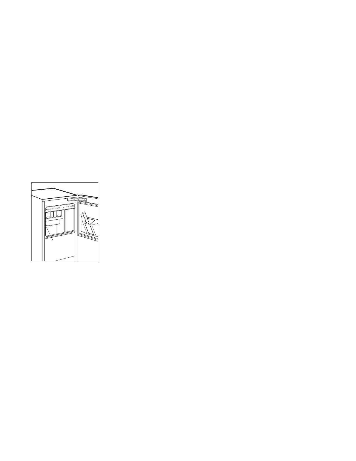
Product Information
Important product information including the model and
serial number are listed on the product rating plate. The
rating plate is located in the upper left corner of the ice
storage bin, on the back of the unit. Refer to the illustration
below.
If service is necessary, contact Sub-Zero factory certied
service with the model and serial number. For the name
of the nearest Sub-Zero factory certied service or for
questions regarding the installation, visit the contact & support section of our website, subzero.com or call Sub-Zero
customer care at 800-222-7820.
Tools | Materials
• Screwdrivers—standard, Phillips and Torx.
• Power drill.
• Standard socket and wrench set.
• 2' level.
• Tubing cutter.
(.9 m) of
• 3'
PEX tubing.
• Saddle valve.
• Material to protect home, ooring and cabinetry during
installation.
1
/4" OD copper, braided stainless steel or
RATING
PLATE
Rating plate location.
subzero.com | 3
Page 4
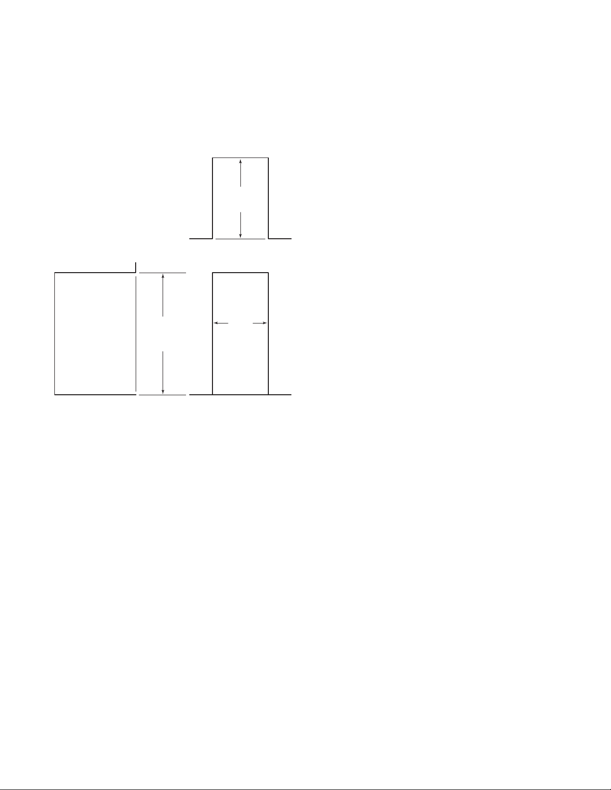
SITE PREPARATION
SIDE
Opening Dimensions
ICE MACHINE
24" (610)
OPENING
DEPTH
TOP VIEW
341/2"
(876)
OPENING
HEIGHT
VIEW FRONT VIEW
IMPORTANT NOTE:
It is recommended that the electrical
151/4"
(387)
OPENING
WIDTH
and water supply be placed in an adjacent cabinet. If they
are placed within the opening, additional cabinet depth may
be required.
4 | Sub-Zero Customer Care 800.222.7820
Page 5

SITE PREPARATION
E
E
E
Electrical
Installation must comply with all applicable electrical codes.
Although it can be located anywhere on the back wall, it
is recommended that the electrical supply be placed in an
adjacent cabinet or in the lower right of the opening. Refer
to the illustration below. A separate circuit, servicing only
this appliance is required.
Model UC-15I(P)O is designed and safe for use in outdoor
applications. When installed outdoors, a ground fault circuit
interrupter (GFCI) is required to reduce the risk of electrical
shock. A GFCI is not recommended for use with the indoor
model and may cause interruption of operation.
ELECTRICAL REQUIREMENTS
Electrical Supply 115 VAC, 60 Hz
Service 15 amp
Receptacle 3-prong grounding-type
CAUTION
The outlet must be checked by a qualied electrician to
be sure that it is wired with the correct polarity. Verify
that the outlet is properly grounded.
WARNING
Do not use an extension cord, two-prong adapter or
remove the power cord ground prong.
Electrical supply location.
subzero.com | 5
Page 6

SITE PREPARATION
24" (610)
ROUGH
OPENING
DEPTH
Plumbing
Installation must comply with all applicable plumbing codes.
The water supply line should be located as shown in the
illustration below. The water supply line should be connected to the house supply with an easily accessible shutoff valve. Do not use self-piercing valves.
A reverse osmosis system can be used provided there is
constant water pressure of 20–80 psi
the unit at all times. A copper line is not recommended for
this application.
PLUMBING REQUIREMENTS
Water Supply Line
Water Pressure 20–80 psi
Excess Water Line for Connection 36" (914)
ICE MACHINE DRAIN
The ice machine can be ordered with or without a drain
pump. Models without a pump will drain water by gravity.
A drain must be installed.
(1.4–5.5 bar) supplied to
1
/4" OD copper, braided stain-
less steel or PEX tubing
(1.4–5.5 bar)
Preparation
CAUTION
Before moving the unit into position, secure the door
closed and protect any nished ooring.
Uncrate the unit and inspect for damage. Remove the wood
base and discard shipping bolts and brackets. Remove and
recycle packing materials. Do not discard the kickplate and
hardware.
Use an appliance dolly to move the unit near the opening.
If the unit has been on its back or side, it must stand upright
for a minimum of 24 hours before connecting power.
The drain and inlet water tubes must be plumbed before
connecting to the ice machine. For the gravity drain, hori-
1
zontal drain lines must have a
/4" (6) per 12" (305) fall. An
air gap will likely be required between the unit and drain.
A stand pipe with a trap below is acceptable for the drain.
8"
(203)
1
/2"
(13)
LOCATION OF
WATER LINE
TOP VIEW
Water supply location.
6 | Sub-Zero Customer Care 800.222.7820
Page 7

INSTALLATION
Installation
INSTALL ICE MACHINE
1 Adjust the leveling legs close to the desired height. Refer
to the illustration below.
2 Reverse the door swing if needed. Refer to steps out-
lined on page 9.
3 Gravity drain model: Install the drain hose provided,
onto the drain tting on the back of unit and route to
the open site drain. Refer to the illustration below and
plumbing requirements on the previous page.
Drain pump model: Route drain tubing through the drain
tting on the back of the unit and install the drain hose
provided, on the drain pump. Route the other end of
the drain tubing to the drain site. Refer to the illustration
below and plumbing requirements on the previous page.
4 Use a compression tting to connect the water inlet on
back of ice machine to the prepared
1
/4" (6) OD cold
water line. Refer to the illustration below.
DRAIN FITTING
5 Open the shut-off valve on the water line. Check all
plumbing connections for leaks. Failure to do so could
result in ooding.
6 Plug the power cord into the grounded receptacle.
7 Level the ice machine to assure the door closes and
seals properly. Place a level on top of the unit and turn
each leveling leg to raise or lower as needed.
8 Move the ice machine into its nal position.
9 Anchor the ice machine by installing two at head
screws provided through each hinge. Refer to the illustration below.
ANCHORING
SCREWS
Leveling.
LEVELING
LEG
Drain connection.
WATER INLET
Anchoring.
subzero.com | 7
Page 8

INSTALLATION
Installation
VERIFY ICE PRODUCTION
1 Press ‘POWER’ to turn the ice machine on.
2 Add one gallon (3.8 L) of cold water to the ice bin. Verify
the water completely drains from the ice bin and there
are no leaks. If the water has not drained within 60 seconds, there may be a kink in the drain tube or incorrect
drain installation.
3 Press ‘CLEAN’. Wait three minutes until the CLEAN light
ashes, then add 1 tablespoon
(15 ml) of undiluted ice
machine sanitizer directly into the spray area. Refer to
the illustration below. Use only the sanitizer made for the
Sub-Zero ice machine available at subzerowolfstore.com.
For questions, contact Sub-Zero customer care at
800-222-7820.
4 A 10-minute sanitizing cycle begins, followed by eight
rinse cycles. When the process is complete, the CLEAN
light will no longer be illuminated. The entire cycle takes
approximately 30 minutes.
5 At initial start-up, the ice machine will need approxi-
mately 30 minutes to freeze ice cubes and up to ve
minutes to harvest. Verify completion of the rst cycle ice
production to conrm proper installation.
WATER
SHUTTERS
Water shutters location.
8 | Sub-Zero Customer Care 800.222.7820
Page 9

INSTALLATION
Installation
REVERSE DOOR SWING
The door hinges are designed to be placed on either the
right or left side of the ice machine. The unit is shipped with
the door hinged on the right. Moving the hinges to the left in
pre-drilled holes, allows for a left-hand door swing.
To reverse door swing:
1 Detach the hinges from the ice machine by removing two
screws per hinge, then remove the door. Remove the
shim located between the cabinet and bottom hinge, this
shim will transfer to the left side bottom hinge.
2 Detach the hinges from the door by removing two
screws per hinge.
3 Detach the right-hand upper trim (shaded area) from the
door by removing two screws. Refer to the illustration
below. Replace it with the left-hand upper trim.
4 Transfer the hinges to the left side of the door and
reinstall. The upper hinge will now be in the lower hinge
position and the lower hinge in the upper hinge position.
5 Remove the top cover of the ice machine by removing
two screws at the top rear of the unit.
6 Remove four screws from the front top rail, then pivot
the top rail end for end to expose the two left-hand top
hinge mounting holes and reinstall. Refer to the illustration below.
7 Remove two screws from the lower edge of the bottom
trim plate and slide it to the right to cover the right hinge
mounting holes. Refer to the illustration below. The left
hinge mounting holes will now be exposed.
8 Reinstall the shim removed in step 1, between the
cabinet and the left side bottom hinge. Reinstall the door
by mounting the hinges using the left hinge mounting
holes. Verify operation of door.
TOP RAIL
SCREWS
HINGE
SCREWS
Remove door.
UPPER
TRIM (RH)
Detach hinges and trim.
HINGE
HINGE
Front top rail.
Bottom trim plate.
TRIM PLATE
SCREWS
subzero.com | 9
Page 10

INSTALLATION
Custom Panel
OVERLAY PANEL
For overlay applications, a custom door panel must be
installed. Panel size is critical for a proper t. To verify panel
requirements and dimensions, refer to the Sub-Zero design
guide at subzero.com/specs.
Finish all sides of the custom panel. They will be visible
when the door is open.
A D-style handle is recommended. The door handle must be
located near the edge of the panel opposite the hinge, centered top to bottom. Stainless steel tubular and pro handles
are avail able through an authorized Sub-Zero dealer. For
local dealer information, visit the nd a showroom section
of our website, subzero.com.
PANEL INSTALLATION
Remove the handle side bracket attached to the front of the
door. Place the custom overlay door panel face down on a
protected work surface. On the back of the panel, position
the plastic template provided, ush with the top and side
edges. Verify proper location for right-hand (RH) or left-hand
(LH) door swing. Refer to the illustration below.
Mark the holes, remove the template and drill pilot holes for
the brackets. Position and secure the mounting bracket with
screws provided.
To install the custom door panel, partially insert a screw in
the center of each mounting position on the hinge side of
the door. Engage the tabbed bracket to the handle side
of the door, then slide the hinge side mounting bracket onto
positioning screws. Slotted holes on the mounting bracket
should slide under screw heads to support the panel. Refer
1
to the illustration below. Panel can be adjusted
/4" (6) up
and down and side to side.
Once the custom panel is in place and properly adjusted,
attach remaining screws to the hinge side mounting bracket
and install hinge covers.
10 | Sub-Zero Customer Care 800.222.7820
Template position.
DOOR
PANEL
BRACKET
SCREW
Panel installation.
CAP
Page 11

INSTALLATION
Completion
KICKPLATE INSTALLATION
Install the kickplate using two screws provided. Refer to
the illustration below. The kickplate must be removable
for service. The oor cannot interfere with removal. Do not
cover the louvered section of the kickplate.
90° DOOR STOP
Door stop pins provided with the ice machine will limit the
door swing to 90°.
To install, open the door to approximately 80°. Insert one
stop pin into the top door hinge (pin enters from the bottom)
and the other stop pin into the bottom door hinge (pin
enters from the top). Refer to the illustration below. Check
for proper operation.
DOOR STOP PIN
HINGE COVERS
Install hinge covers once installation of the ice machine is
complete and door stop pins have been installed (if applicable). The knock-out in the hinge cover must be removed
if the 90° door stop is used.
Verify hinges are free of dirt or grease before applying
covers. To install, remove paper backing and apply hinge
covers to each hinge. Attach the magnetic center covers.
Refer to the illustration below.
WARNING
Follow all city and state laws when storing, recycling or
discarding unused refrigerators and freezers.
KNOCK-OUT
90° door stop.
Sub-Zero, Sub-Zero & Design, Dual Refrigeration, The Living Kitchen, Great American Kitchens The Fine Art of Kitchen Design, and Ingredients are registered trademarks and service
marks of Sub-Zero, Inc. Wolf, Wolf & Design, Wolf Gourmet, W & Design and the color red as applied to knobs are registered trademarks and service marks of Wolf Appliance, Inc.
All other trademarks or registered trademarks are property of their respective owners in the United States and other countries.
Hinge covers.
subzero.com | 11
Page 12

SUB-ZERO, INC. P.O. BOX 44848 MADISON, WI 53744 SUBZERO.COM 800.222.7820
7024818 REV-C 8/2016
 Loading...