

Page 1
SZ-7512-P
OPERATING
INSTRUCTIONS
4
To set other
parameters.
Display will show ‘P5’ & flash
to go other parameters, use
UP / DOWN keys.
Press and
DOWN(prg)
key for
2 seconds.
hold
prg
Introduction: SZ-7512-P(Antifreeze thermostat)
Operating Instructions
The SZ-7512-P is a digital antifreeze thermostat with manual reset
O
facility and alarm (Buzzer) facility, this has a fixed differential of 2 C
The SZ-7512-P can be used as a direct replacement to the
following mechanical antifreeze thermostats :-
(a) Honeywell T675-B, (b) Danfoss-KP61, (c) Ranco-6953,
(d) Johnson A19ACA-15C,(e) White Rodgers 16A60-9.
The alarm is automatically set equal to the set point and can be
muted with the ‘RST’ key.
The controller functions similar to the above mentioned
mechanical thermostats i.e. relay will go off when the set point is
achieved and the same can be restarted only if the differential is
reached and the ‘RST’ key is pressed.
1
INDEX
2
Para. Page
Description
P5
LP
AL
FS
EP
3
4
5
6
7
8
9
10
12
13-14
To set the Set Point of the controller.
How to set other parameters.
Probe calibration.
Keypad lock.
Alarm - to activate buzzer.
Restore factory defaults.
End Programming & keypad functions.
Operating messages.
Wiring Diagram.
Panel cutout & dimensions.
3
Function: T
point of the controller.
o set the cut out
Display will change to set range
flash. The set point range can now
be changed by using the
UP/DOWN keys. After setting the
desired range, press the SET key
and you will see“_ _ _" which
confirms that the set point has
been stored in memory.
Set point
Press and
the SET
key for
2 seconds.
hold
-50
O
C
50
O
C
3
O
C
Min
Max
Fac.
www.ascontrols.com
INDIA
Page 2
P5
parameter
Function: To set probe
calibration.
To change
the P5
parameter,
press the
SET key.
Use UP/DOWN keys to set desired
range.
In time it may be possible that the
display may be offset by a degree
or so.
To compensate for this error, you
may need to add or minus the
degrees required to achieve the
correct temperature. Setting range
O O
is from -10 C to + 10 C
O
-10 C
Min Max
Fac.
O
+10 C
O
0 C
Example: The temperature on
O
the display is 28 C, whereas the
O
actual temperature is 30 C. You will
need to set the P5 mode to 2,
which means that once out of the
programming mode, the display will
show the temperature
O O O
30 C (28 C + 2 C).
5 6
LP
parameter
Function : To lock keypad.
0 1 0
Min Max
Fac.
To change
the LP
parameter,
press the
SET key.
Use UP/DOWN keys to set desired
range.
This Parameter can lock the
keypad so that tampering is not
possible by by-standers.
When set to
0= keypad unlocked
1= keypad locked
When locked all parameters can
only be viewed, but not modified.
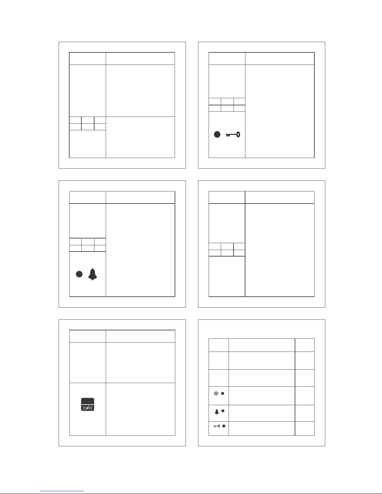
7
AL
parameter
0 1 1
Function: To activate / deactivate
alarm.
To change
the AL
parameter,
press the
SET key.
Use the UP/DOWN keys to set
alarm on or off. Once set to on, the
buzzer will come on incase the
temperature is equal to the set
point.
1 = Activates Buzzer.
0 = Deactivates Buzzer.
Note=Alarm will be ON in probe
fail condition irrespective of
AL parameter
Min Max
Fac.
FS
Parameter
Function : To restores default
settings of the controller.
To change
the FS
parameter,
press the
SET key.
When set to 1 all parameters
are programmed to default
values.
Useful to debug setting related
problems.
0 1 0
Min Max
Fac.
8
9
EP
Parameter
Function : To end programming.
To end
programming
press the
SET key
Once the SET key is pressed,
the controller goes into the
normal mode and displays the
temperature and all settings are
recorded.
This key will reset the relay and
mute the buzzer alarm.
Reset key
RST
10
Operating messages and Icon status
Parameter
Set Point
AL , P3
Message Description
Lt
Temperature is equal to the set point.
PP
Probe short circuit, circuit open or without
0 0
probe, or temperature >50 C or < -50 C
Alarm (Lt or PP)
LP
Keypad locked/unlocked.
O
SP + 2 C
Compressor Relay On/Off.
On/Off
On/Off
Flashing
Page 3

9
12
+
-
BUZZER
To SZ-B75
(10Vdc, 10mA max)
Low TempTrip Lamp
or Other Load (5A max)
Compressor or
Contactor
or Heater
8(3)A max)
Caution : Wiring Shown for 230Vac Loads Only.
12
11
15 16
Installation : Fixing and dimensions of panel models:
To fix the unit, slide the fastener 1 through the guides 2
as per the position shown in the figure. Move the fastener in
the direction of the arrow, pressing tab 3 it permits to move
the fastener in the opposite direction of the arrow. Once the
controller has been connected, they should be covered with
the lid 4 Silicon sealant should be applied along the
perimeter of the panel cut out or a rubber ‘O’ ring supplied
before the unit is fitted to obtain IP65 grade.
Alarm (Buzzer) : Only use SZ-B75 buzzer with SZ7512-P series controller. Use of any other type of result
in permanent damage to the controller and may cause
personal injury.
Controller :Controller should be installed in a place
protected by vibration, water and corrosive gasses and
where ambient temperature does not exceed the
values specified in the technical data.
Probe :To give a correct reading, the probe must be
installed in a place protected from thermal influences,
which may affect the temperature to be controlled.
CAUTION
WIRING: The probe and its corresponding wires should never
be installed in a conduit next to control or power supply lines.
The electrical wiring should be done as shown in the diagram.
The power supply circuit should be connected to a protection
switch. The terminals admit wires of upto 2.5sq mm.
WARNING: Improper wiring may cause irreparable damage
and personal injury. Kindly ensure that wiring
is done by qualified personnel only.
Maintenance: Cleaning: Clean the surface of the controller
with a soft moist cloth. Do not use abrasive detergents, petrol,
alcohol or solvents.
Notice: The information in this document is subject to change
in order to improve reliability , design or function without prior
notice and does not represent a commitment on the part of the
company. In no event will the company be liable for direct,
indirect, special, incidental or consequential damage arising out
of the use or inability to use the product or documentation, even
if advised of the possibility of such damages. No part of this
manual may be reproduced or transmitted in any form or by any
means without the prior written permission of the company.
13
GASKET
PANEL
Side Lock
CONTROLLER
14
SZ-7512-P
prg
SET
O
C
RST
3
1
4
2
34.5mm
71mm
19mm
10mm
MAX
71mm
29mm
Panel cutout
PANEL
Suggested Wiring Diagram
PROBE
230VNCCNO
RELAY
11
10
Technical data :
≤
Display : 14.2 mm (0.56") LED.
Data storage : Non-volatile EEPROM memory
Power input : 230Vac,+/-10%, 50Hz/60Hz. Others on
request.
O O
Operating temp. : 5 C to 50 C(non-condensing).
O O
Storage temp : -20 C to 70 C(non-condensing).
Output : 1 SPDT relay 8(3)A, 250Vac
Input : NTC probe, SZ-N75
O O
Range : -50 C to 50 C
O
Resolution : 1 C
O
Accuracy : +/-1 C
O O
Probe tolerance at 25 C : +/-0.3 C
Alarm (buzzer) : SZ-B75, 10Vdc, 10mA
Housing : Black ABS plastic.
Front cover : Polycarbonate plastic.
Dimensions : Front - 75 x 34.5 mm,
Depth 71 mm (w/o back lid).
Panel Cutout : 29mm x 71mm
Mounting : Flush panel mounting with fasteners.
Protection : Front panel is water proof & IP 65 rated .
Connections : Screw terminal blocks.
2.5 sq.mm wire terminal only
Page 4

INDIA
Ball Valves
Globe Valves
Hand Valves
Flow Switches
Solenoid Valves
OUR OTHER PRODUCTS
Cold Room Controller
Chiller Controller
Two Compressors Controller
Heating Controller
Humidity Controller
Pressure Controller
TM
00 / 25.11.09
18
LIMITATION OF LIABILITY : ASCPL's total liability for any and
all losses and damages arising out of any cause whatsoever
shall in no event exceed the purchase price of the products or
parts in respects of which such cause arises, whether such
cause be based on theories of contract, negligence, strict liability,
tort or otherwise.
In no event is ASCPL responsible for any consequential or
punitive damages or losses of any nature whatsoever. ASCPL
shall not be liable for, and buyer assumes any liability for, all
personal injury and property damage connected with the
17
Warranty : All Subzero products manufactured by A.S.Controls
Pvt. Ltd (thereafter reffered to as ASCPL) are under warranty
against defects in workmanship and materials for a period of one
year from date of shipment from factory. This warranty is in force
only when products are properly installed,maintained and
operated in use and service as specifically stated in Subzero
catalogues.
Defective products, or parts there of returned to the factory with
transporatation charges prepaid and found to be defective by
factory inspection, will be replaced or repaired at ASCPL's
option, free of charge, Ex-factory. Warranty does not cover
products that have been altered, or repaired in the field, or
damaged in transit, or have suffered accidents, misuse, or abuse.
Products disabled by dirt or other foreign substances will not be
considered defective. This warranty does not cover any cosmetic
issues, such as product damaged by accident, abuse and misuse
as a result of service or modification other than company. Repair
or change in parts or replacement of parts or products does not
extend the warranty.
The express warranty set forth above constitutes the only
warranty applicable to ASCPL products, and is in lieu of all other
warranties, expressed or implied. No employee, agent, dealer or
any other person is authorised to give any warranties on behalf of
ASCPL, nor to assume for ASCPL, any other liability in
connection with any of its products.
19
handling, transporatation, possession, further manufacture, other
use or resale of the products, whether used alone or in
combination with any other products or materials. ASCPL makes
NO other warranty, expressed or implied, and makes no warranty
of merchantibility or fitness for any particular purpose.
From time to time buyers might call to ask ASCPL for technical
advice based upon limited facts disclosed to ASCPL. If ASCPL
furnishes technical advice to the buyer, whether or not at buyer's
request, with respect to application, further manufacture or use of
the products or parts, ASCPL shall not be liable for such technical
advice or any such advice provided to buyer by any third party
and buyer assumes all risks of such advice and results thereof.
NOTICE TO USERS OF PRODUCTS : The Limited Warranty
stated above is a factory warranty to the first purchasers of
ASCPL products. Since many users have purchased these
products from ASCPL distributors, the user must within thirty (30)
days after user's discovery of what the user believes is a defect,
notify in writing and return the product to the distributor from
whom he purchased the product/part. The distributor may or may
not at the distributor's option choose to submit the products/parts
to ASCPL pursuant to this limited warranty. Failure by the buyer
to give such written notice within 30 (thirty) days shall be deemed
an absolute and unconditional waiver of buyers claim for such
20
defects. Acceptance of any alleged defective product/parts by
ASCPL's distributor for replacement or repairs under the terms
of ASCPL's limited warranty in no way determines ASCPL's
obligations under this Limited Warranty.
Because of a policy of continous product improvement, ASCPL
reserves the right to change designs, materials or specifications
without notice.
Disclaimer: This manual & its contents remain the sole property
of A.S. CONTROLS Pvt. Ltd, India and shall not be reproduced
or distributed without authorisation. Although great care has
been taken in the prepartion of this document, the company or
its vendors in no event will be liable for direct, indirect, special,
incidental or consequential damage arising out of the use or
inability to use the product or documentation, even if advised of
the possibility of such damages. No part of this manual may be
reproduced or transmitted in any form or by any means without
the prior written permission of the company. A.S. CONTROLS
Pvt. Ltd, reserves the right to make and changes or
improvements without prior notice.
 Loading...