

Page 1
OPERATING
INSTRUCTIONS
SZ-7510-P-DI
www.subzero.co
1
4
GENERAL DESCRIPTION
The Sub-Zero Series SZ-7510-P-DI are aesthetically superior
versions of their predecessors. The SZ-7510-P-DI is a single
set point controller. with digital input. They are specifically
des ign ed for ref riger ati on app lic ation s wh erein the
compressor cuts off at set point and is restarted at a
temperature of set point plus differential.
Additionally these controllers offer several protection features
that are easily understood by the examples in the instructions
below. The controller can be used for heating applications,
when the P1 parameter is set to “1” .
A number of parameters are displayed alphanumerically to set
up the instrument for each specific application.
The SZ-7510-P-DI controller can be used for several
O O
applications with a measuring range from -50 C to 99 C.
Instructions :
Function: To set the cut out
point of the controller.
Display will change to set range.
The set point range can now be
changed by using the UP/DOWN
key. After setting the desired
range, press the set key and you
will see “- - -” which confirms that
the set point has been stored in
memory.
Set point
Press and hold
the SET
key for
2 Seconds.
O
-50
C
O
99
C
O
10 C
Min
Max
Fac.
3
INDEX
Para. Page
Description
P1
P2
P3
P4
P5
P6
d0
d1
d2
d3
LP
E1
FS
EP
3
4
5
6
7
8
9
10
11
12
13
14
15
16
17
18
19
20
21
22
2
INDIA
To set other
Parameters.
Display will show P1 & flash.
To go to other parameters,
use UP/DOWN keys.
Press & hold
the DOWN(prg)
key for
2 seconds.
prg
SET
To set the SET Point of the controller.
How to set other parameters.
To set Heating or Cooling function.
Max High Temp limit & alarm.
Min Low Temp limit & alarm.
To set Differential (Hysterisis).
Probe calibration.
Time Delay (relay restart after cutoff)
Keypad lock.
Relay status on probe failure.
Restore factory defaults.
End Programming.
Operating messages.
Technical Data.
Wiring diagram.
Panel cutout & dimensions.
Activate or deactive digital input function.
Set reset mode for digital input
Set the count mode for CCF
Set the number of count for CCF
Page 2
5
P1 Parameter
Function: To set controller for heating
or cooling.
0 1 0
To change
the P1
parameter,
press the
SET key.
Use UP/DOWN keys to get
desired range & press set
to confirm.
0: Cooling mode and
1: Heating mode.
Min Max
Fac.
6
7
8
P4 Parameter
Function: To set the differential.
To change
the P4
parameter,
press the
SET key.
Use UP/DOWN keys to set
desired range.
Differential between cut out and
cut in temperature can be set
O O
between 1 C to 20 C.
O
1 C
Min Max
Fac.
O
20 C
O
2 C
Example (in cooling mode): If the
O
set point is set at 10 C and
O
differential is set at 2 C, then when
O
the system reaches 10 C, the relay
will cut out. Since the differential is
2, the relay will cut in (restart) at
O O O
12 C (10 C+2 C).
9
P5 Parameter
Function: To set probe calibration.
To change
the P5
parameter,
press the
SET key.
Use UP/DOWN keys to set desired
range.
In time it may be possible that the
display may be offset by a degree
or so.
To compensate for this error, you
may need to add or minus the
degrees required to achieve the
correct temperature. Setting range
O O
is from -10 C to +10 C.
O
-10 C
Min Max
Fac.
O
10 C
O
0 C
Example: The temperature on
O
the display is 28 C, whereas the
O
actual temperature is 30 C. You will
need to set the P5 mode to 2,
which means that once out of the
programming mode, the
temperature will show
O O O
30 C (28 C + 2 C).
10
Function: To set minimum allowable
low temperature set point.
Use UP/DOWN keys to set desired
range. Once set at a particular
range, this will not allow the set
point to go below this range.
Example: Setting this parameter at
O
-30 C will not allow the set point to
O
go below -30 C. Also, if the
O
temperature reaches -30 C, the
display will show Lt (LowTemp.)
indicating that the temperature has
gone below the range in this
parameter.
P3 Parameter
O
-50 C
Max
Fac.
O
XX CO-50 C
To change
the P3
parameter,
press the
SET key.
Min
(Message on display)
P6 Parameter
0 Min
99 Min
3 Min
Function: To set time delay
between relay restart time.
To change
the P6
parameter,
press the
SET key.
Min
Max
Fac.
Use UP/DOWN keys to set desired
range.
This parameter is used to protect
the compressor from restarting in a
short period of time and can be set
between 0 to 99 minutes.
Example: If this parameter is set at
3 minutes, the relay will cut off at
the set temperature, but will not
restart for a minimum of 3 minutes,
even if the differential is achieved
earlier. This parameter is good to
protect the life of the compressor
when there are power fluctuations
and the compressor is switched off
and on within a few seconds.
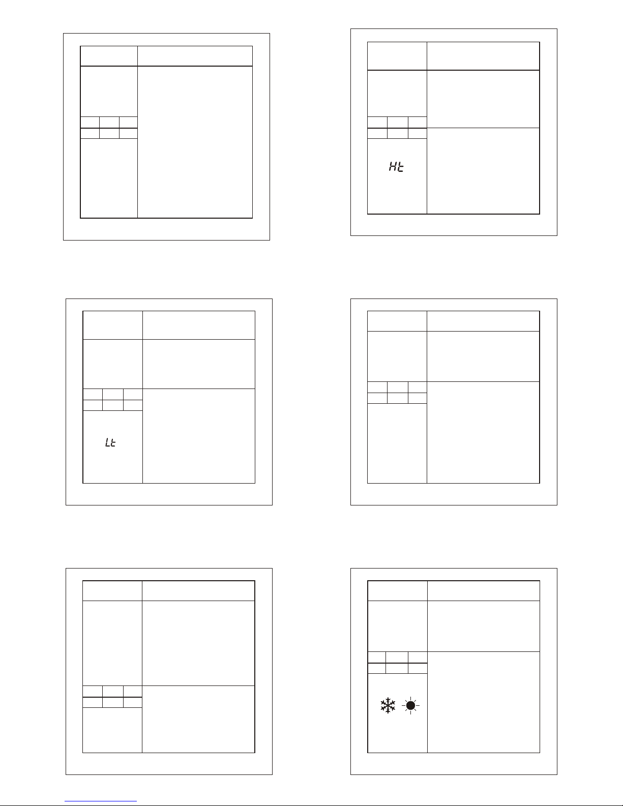
P2 Parameter
Function: To set maximum allowable
high temperature limit.
O
XX C
To change
the P2
parameter,
press the
SET key.
Max
Fac.
Use UP/DOWN keys to set
desired range.
Once set at a particular
range, this will not allow the
set point to go above this
range.
O
99 CO99 C
Example: Setting this parameter
O
at 25 C will not allow the
O
set point to go above 25 C. Also,
O
if the temperature reaches 25 C,
the display will show Ht (High Temp.)
indicating that the temperature.
has gone above the range in this
parameter.
Min
(Message on display)
Flashing
Time delay in progress
Page 3

15
LP Parameter.
0 1 0
Function: To lock keypad.
To change
the LP
parameter
press the
SET key.
Use UP/DOWN keys to set
desired range.
This parameter can lock the
keypad so that tampering is not
possible by by-standers.
0 = keypad unlocked
1 = keypad locked
When locked all parameters can
only be viewed, but not modified.
Min Max
Fac.
16
E1 Parameter
0 2
2
Function : Relay status on
Probe Failure.
Min Max
Fac.
To change
the E1
parameter
press the
SET key.
Use UP/DOWN keys to set
desired range.
When set to
0 = Relay status is ON.
1 = Relay performs a duty cycle
10 minutes ON and 4minutes
OFF.
2 = Relay status is OFF.
11
d0 Parameter
0 2 1
Function : To activate or deactive
digital input function.
To change
the d0
parameter
press the
SET key
Use UP/DOWN keys to set
desired range.
0: Digital input disable.
1: DI with 230VAC present
2: DI with 0VAC present.
Min Max
Fac.
Example :
If this parameter is set to 0,
controller will not sense any digital
input.
If set to 1, when 230VAC is
present, controller will treat it as a
fault and turn off the compressor
and DI ( )will flash.
If set to 2, when 0VAC is present,
controller will treat it as a fault and
turn off the compressor and
DI ( )will flash.
12
d1 Parameter
Function : To set reset mode for
digital input.
0 1 0
Min Max
Fac.
To change
the d1
parameter
press the
SET key
Use UP/DOWN keys to set desired
range.
0: Auto reset.
1: Manual reset.
Example :
If this parameter is set to 0, then
incase of a fault in d0 parameter,
unit will auto reset after fault is
cleared.
If this parameter is set to 1, then
incase of a fault in d0 parameter,
unit will allow reset after pressing
AUTO/MAN button. (after d0 fault is
cleared).
14
13
Use UP/DOWN keys to set desired
range.
This parameter sets the permissible
number of reset cycles of
compressor.
When number of compressor reset
cycles within 1 Hr. goes above the
d3 parameter, controller switch to
manual reset mode and “CCF”
led will be ON.
NOTE: This parameter saves the
compressor from multiple (more
than max.10 nos.) reset within 1 Hr.
Use RST key to reset this CCF
fault.
Use UP/DOWN keys to set desired
range.
0: CCF count increment with each
Comp. OFF and DI fault.
1: CCF count increment only with
DI fault.
d3 Parameter
d2 Parameter
0
0
1015
0
Min
Min
Max
Max
Fac.
Fac.
To change
the d2
parameter
press the
SET key
To change
the d2
parameter
press the
SET key
Function : To set the number of reset
cycles of compressor.
Function : To set the count mode for CCF .
CCF- compressor count fault.
RST
AUTO
MAN
Page 4

20
Technical data:
Dimensions: Front : 75 X 34.5 MM,
Depth 7 MM (w/o back lid)
: 1
Mounting: Flush panel mounting with fasteners
Frontal protection : I.P65
Connections: Screw terminal blocks. 2.5sqmm one
wire/ terminal only
Display: 2 X14.2 mm (0.56") LED
Data storage: Non-volatile EEPROM memory
Power input: 230Vac +/-10%,50-60Hz.
Other on request
O O
Operating temp.: 5 C to 50 C(non-condensing)
O O
Storage temp: -20 C to 70 C(non-condensing)
Output:1 SPDT relay 8 (3)A, 250Vac.
Input: NTC probe, SZ-N75
O O
Range: -50 C to 99 C
O
Resolution: 1 C
O
Accuracy: +/- 1 C
O O
Probe tolerance: +/- 0.3 C at 25 C
Housing : Black, ABS Plastic
Front Cover : Red Polycarbonate plastic.
18
EP Parameter.
To end
programming
press the
SET key
Once the SET key is pressed, the
control goes into the normal mode
and displays the temperature and
all settings are recorded.
Function: To end programming.
21
NEUTRAL
To
SZ-N75
Compressor, Contactor
or Heater 8(3)A max
PHASE
Caution:Wiring for 230Vac load only
230V
NO NC C
7
11 12
8
5
3 4
1
6
PROBE
COMP.
Phase from
Digital Input
trip contact
Neutral
3
1
4
2
35mm
71mm
19mm
15mm
MAX
71
29
Panel cutout
22
RST
SZ-7510-P-DI
prg
SET
-
DI
CCF
AUTO
MAN
RST
19
Operating messages and Icon status
Parameter
Message
Description
P2
Ht
Temperature above the maximum
limit of the set point.
P3
Lt
Temperature below the minimum limit
of the set point.
PP
Probe short circuit, circuit open or without
0 0
probe, or temperature > 99 C or <-50 C
SP, P4
Comp. Relay on/off
On/Off
P6
Time delay in progress
Flashing
LP
Keypad locked/unlocked
d0,d1
d2,d3
Digital input fault ON
Compressor count fault : CCF
On
On/Off
DI
On
CCF
17
FS Parameter
Function : To restore default
settings of the controller.
0
1 0
Min Max
Fac.
To change
the FS
parameter
press the
SET key.
When set to 1 all parameters
are programmed to factory
values.
Useful to debug setting
related problems.
Page 5

25
Disclaimer: This manual & its contents remain the sole property
of A.S. CONTROLS Pvt. Ltd, India and shall not be reproduced or
distributed without authorisation. Although great care has been
taken in the prepartion of this document, the company or its
vendors in no event will be liable for direct, indirect, special,
incidental or consequential damage arising out of the use or
inability to use the product or documentation, even if advised of the
possibility of such damages. No part of this manual may be
reproduced or transmitted in any form or by any means without the
prior written permission of the company. A.S. CONTROLS Pvt. Ltd,
reserves the right to make and changes or improvements without
prior notice.
Warranty: This product is warranted against defects in
materials and workmanship for a period of one year from
the date of purchase. During the warranty period, product
determined by us to be defective in form or function will be
repaired or, at our option, replaced at no charge. This
warranty does not apply if the product has been damaged
by accident, abuse, and misuse or as a result of service or
modification other than by the company. This warranty is in
lieu of any other warranty expressed or implied. In no event
shall the company be held liable for incidental or
consequential damages, including lost revenue or lost
business opportunity arising from the purchase of this
product..
INDIA
Ball Valves
Globe Valves
Hand Valves
Flow Switches
Solenoid Valves
OUR OTHER PRODUCTS
Cold Room Controller
Chiller Controller
Two Compressors Controller
Heating Controller
Humidity Controller
Pressure Controller
TM
24
CAUTION
WIRING: The probe and its corresponding wires should never
be installed in a conduit next to control or power supply lines.
The electrical wiring should be done as shown in the diagram.
The power supply circuit should be connected to a protection
switch. The terminals admit wires of upto 2.5sq mm.
WARNING: Improper wiring may cause irreparable damage
and personal injury. Kindly ensure that wiring is done by
qualified personnel only.
Maintenance: Cleaning: Clean the surface of the controller
with a soft moist cloth. Do not use abrasive detergents, petrol,
alcohol or solvents.
Notice: The information in this document is subject to
change in order to improve reliability , design or function
without prior notice and does not represent a commitment
on the part of the company. In no event will the company
be liable for direct, indirect, special, incidental or
consequential damage arising out of the use or inability to
use the product or documentation, even if advised of the
possibility of such damages. No part of this manual may
be reproduced or transmitted in any form or by any means
without the prior written permission of the company.
23
Installation : Fixing and dimensions of panel models:
To fix the unit, slide the fastener 1 through the guides 2
as per the position shown in the figure. Move the fastener in
the direction of the arrow, pressing tab 3 it permits to move
the fastener in the opposite direction of the arrow. Once the
controller has been connected, they should be covered with
the lid 4 .
Silicon sealant should be applied along the perimeter of the
panel cut out or a rubber ‘O’ ring supplied before the unit is
fitted to obtain IP65 grade.
Controller :Controller should be installed in a place
protected by vibration, water and corrosive gasses and
where ambient temperature does not exceed the
values specified in the technical data.
Probe :To give a correct reading, the probe must be
installed in a place protected from thermal influences,
which may affect the temperature to be controlled.
 Loading...