

Page 1
G RILL M ODULE
INSTALLATION INSTRUCTIONS
Page 2
CONTACT
INFORMATION
Wolf Customer
Service:
800-332-9513
Website:
wolfappliance.com
As you follow these instructions, you will
notice WARNING and CAUTION symbols.
This blocked information is important for the
safe and efficient installation of Wolf equipment. There are two types of potential
hazards that may occur during installation.
WOLF®is a registered trademark of Wolf Appliance Company, LLC
signals a situation where minor injury or
product damage may occur if you do not
follow instr
states a hazard that may cause serious
injury or death if precautions are not
followed.
Another footnote we would like to identify is
IMPORTANT NOTE: This highlights information that is especially relevant to a problemfree installation.
uctions.
Page 3
WOLF GRILL MODULE
INSTALLATION REQUIREMENTS
IMPORTANT NOTE:
Save these Installation
Instructions for the local inspector’s use.
Please read the entire Installation
nstructions prior to installation.
I
This installation must be completed by a
qualified technician.
Installer:
please retain these instructions
for local inspector’s reference, then leave
them with the homeowner.
Homeowner:
please read and keep
these instructions for future reference and
be sure to read the entire Use & Care
Information prior to use.
IMPORTANT NOTE:
This appliance must be
installed in accordance with National Electrical Codes, as well as all state, municipal and
local codes. The correct voltage, frequency
and amperage must be supplied to the appliance from a dedicated, grounded circuit
which is protected by a properly sized circuit
breaker or time delay fuse. The proper
voltage, frequency, and amperage ratings are
listed on the product rating plate.
BEFORE YOU START
IMPORTANT NOTE:
Installation and service
must be performed by a qualified installer or
ervice agency. Warranty service must be
s
performed by a Wolf authorized service center.
Installation of the grill module must meet
the minimum clearance requirements for
afe operation. Refer to Site Preparation on
s
page 4.
If the grill module is to be used with any
combination of additional cooktop units or
modules, refer to Multiple Cooktop Installation on page 6.
Electrical installation must be adequate
and in compliance with all local codes and
ordinances. Electrical ground is required,
refer to Electrical Requirements on page 8.
IMPORTANT NOTE:
A ventilation hood is
recommended (but not required) for use with
the Wolf electric grill module.
This module is intended for indoor use.
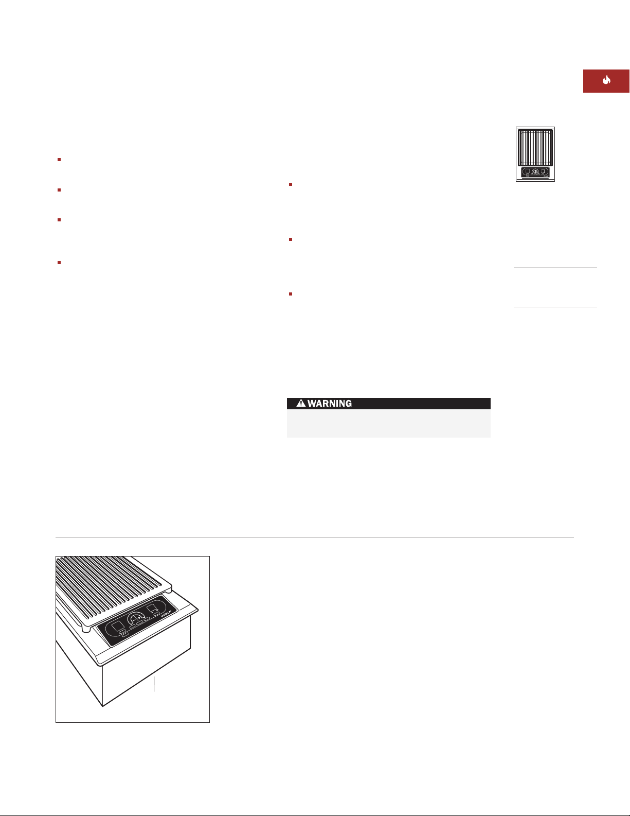
odel IG15/S
M
Model Number
IG15/S
Serial Number
Record the model and serial numbers before
installing the grill module. Both numbers are
listed on the product rating plate located on
the underside of the module. Refer to the
illustration below.
Location of rating
plate under module
Rating plate location
3
Page 4
WOLF GRILL MODULE
C
G
D
A
B
B
E
F
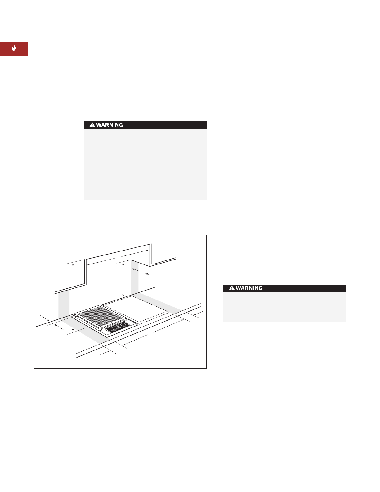
SITE PREPARATION
IMPORTANT NOTE:
Installation of the Wolf
electric grill module must meet the following
ocation requirements. All dimensions listed
l
are minimum requirements for safe operation.
Refer to the illustration below.
T
o eliminate the risk of burns or fire by
reaching over heated surface units,
cabinet storage space located above the
surface units should be avoided. If
cabinet storage is to be provided, the risk
can be reduced by installing a ventilation
hood that projects horizontally a
minimum of 5" (127) beyond the bottom
cabinets.
LOCATION IN COUNTERTOP
inimum flat countertop surface. Must be
A)M
equal to or greater than the width of the
module(s).
B)
Minimum 6" (152) wide clearance from the
module side edge to any combustible
surface up to 18" (457) above the countertop (noted by shaded area).
OVERHEAD CABINET DIMENSIONS
C)
Minimum spacing between overhead side
cabinets must be greater than or equal to
the nominal width of the module(s).
D)
Minimum 18" (457) vertical distance from
the countertop to the bottom of side
cabinets within minimum side clearance.
E)
Minimum vertical distance between the
countertop and combustible materials
above the module must be 30" (762).
F)
Minimum 1" (25) from rear wall.
G)
Maximum 13" (330) depth of overhead and
side cabinets directly above and within side
clearance.
Minimum installation clearances
4
Failure to locate the cooktop module
without the proper clearances will result
in a fire hazard.
Page 5

E
61/4"
(159)
15"
(381)
15"
(381)
7"*min (178)
CUT-OUT TO
COMBUSTIBLE
MATERIALS
(BOTH SIDES)
14" (356)
COOKTOP CUT-OUT
WIDTH
14" (356)
COOKTOP CUT-OUT
WIDTH
33" (838)
RECOMMENDED
CABINET WIDTH
18"
(457)
NOTE: Application shown allows for installation of two 15" (381) modules side-by-side with 33" (838) recommended cabinet width. 18" (457)
recommended cabinet width for installation of single 15" (381) cooktop or module. *Minimum clearance from both side edges of cooktop cut-out
to combustible materials up to 18" (457) above countertop. **Minimum clearance from rear edge of cooktop cut-out to combustible materials up
to 18" (457) above countertop.
191/4" (489)
COOKTOP CUT-OUT
DEPTH
21/2"min
(64)
36" (914)
STANDARD
FLOOR TO
COUNTERTOP
HEIGHT
13" max
(330)
30" (762)
COUNTERTOP TO
COMBUSTIBLE
MATERIALS
ABOVE COOKTOP
FRONT OF COUNTERTOP
21/2"min
(64)
191/4" (489)
COOKTOP
CUT-OUT DEPTH
2"**
(64)
15" (381)
OVERALL WIDTH
21"
(533)
OVERALL
DEPTH
61/4"
(159)
INSTALLATION INSTRUCTIONS
INSTALLATION SPECIFICATIONS
The illustrations below provide the overall
dimensions, finished cut-out dimensions and
lectrical placement for the Wolf electric grill
e
module.
The grill module is designed to fit a standard
24" (610) deep base cabinet with 25" (635) deep
ountertop. Before making the countertop cut-
c
out, verify that the module will clear the side
walls of the base cabinet below.
A grounded junction box needs to be placed
within 4' (1.2 m) of the right rear of the module.
Locate electrical with the shaded area of the
illustration below.
MODEL IG15/S DIMENSIONS
verall Width 15" (381)
O
Overall Height 61/4" (159)
Overall Depth 21" (533)
Minimum Cabinet Depth 223/4" (578)
Minimum Height Clearance 61/4" (159)
Cut-Out Width 14" (356)
Cut-Out Depth 191/4" (489)
Unit dimensions may vary to ±1/8" (3).
Overall Dimensions
Installation Specifications
Countertop Cut-Out
Dimensions
Dimensions in parentheses are in
millimeters unless otherwise specified.
5
Page 6

WOLF GRILL MODULE
21/2"min
(64)
FRONT OF COUNTERTOP
191/4"
(489)
CUT-OUT
DEPTH
291/4" (743)
TWO MODULES WIDTH
441/2" (1130) THREE MODULES WIDTH OR
441/4" (1124) 30" COOKTOP AND ONE MODULE
593/4" (1518) FOUR MODULES WIDTH OR
591/2" (1511) 30" COOKTOP AND TWO MODULES OR
501/4" (1276) 36" COOKTOP AND ONE MODULE
14"
(356)
CUT-OUT
WIDTH
MULTIPLE COOKTOP INSTALLATION
IMPORTANT NOTE:
If the grill module is to be
used with a combination of additional cooktop
nits or modules with a filler strip, the cut-out
u
width is calculated by adding the corresponding units' cut-out dimensions plus 1
or each additional unit.
f
hen multiple units are installed side by side,
W
1
/4" (32)
each unit must have its own separate recommended electrical circuit.
When two or more modules are installed
together, an integrated module filler strip
(IFILLER/S) is recommended.
IMPORTANT NOTE:
Review specific
installation instructions for product to product
apabilities.
c
6
Countertop cut-out dimensions for installation of multiple cooktops
Page 7

INSTALLATION INSTRUCTIONS
VENTILATION OPTIONS
IMPORTANT NOTE:
It is recommended that
you operate the Wolf electric grill module with
ither a Wolf cooktop or Pro ventilation hood
e
or hood liner. Contact your Wolf dealer for
details.
Cooktop Wall Hood –
idths in classic stainless steel.
w
Cooktop Island Hood –
30" (762) or 36" (914)
42" (1067) width in
classic stainless steel.
Pro Wall Hood –
22" (559), 24" (610) or
27" (686) depths and 30" (762) to 66" (1676)
widths in classic stainless steel.
Pro Island Hood –
36" (914) to 66" (1676)
widths in classic stainless steel.
Pro Hood Liner –
available in widths to
accommodate 30" (762) to 60" (1524) hoods.
All hoods have welded seams, sealed halogen
lighting and removable, dishwasher-safe
filters.
IMPORTANT NOTE:
Wolf does not recommend the use of downdraft ventilation with the
grill module.
ACCESSORIES
Optional accessories are available
through your
Wolf dealer. To
obtain local dealer
information, visit
the Locator section
of our website,
wolfappliance.com.
IMPORTANT NOTE:
When installing a ventilation hood, refer to the specific requirements of
the hood for the minimum dimension to the
countertop.
Dimensions in parentheses are in
millimeters unless otherwise specified.
7
Page 8

WOLF GRILL MODULE
ELECTRICAL REQUIREMENTS
Verify that power is disconnected from
the junction box before proceeding.
Required Power Supply
240 VAC, 60 Hz, 15 amp service
208 VAC, 60 Hz, 15 amp service
Maximum Connected Load
2.8 kW at 240 VAC
2.1 kW at 208 VAC
The Wolf electric grill module requires a
separate, grounded 3-wire 240/208 V AC, 60 Hz,
15 amp service with its own circuit breaker.
The module is provided with a 4' (1.2 m)
flexible 3-wire conduit that makes a connection
to a junction box. The conduit consists of two
insulated hot lead conductors (copper) and one
insulated ground conductor (copper). Locate
electrical within the shaded area shown in
the Installation Specifications illustration on
page 5.
For electrical installation, attach the conductors
to the residence wiring in accordance with
ational Electrical Codes and all state, provin-
N
cial, municipal and local codes.
The wiring diagram covering the control circuit
is located inside the module control box.
The complete appliance must be properly
grounded at all times when electrical
power is applied.
Do not ground the appliance with the
neutral (white) house supply wire. A
separate gr
If aluminum house supply wiring is
utilized, splice the appliance copper wire
to the aluminum house wiring using
special connectors designed and agency
certified for joining copper and
aluminum. Follow the connector manufacturer's recommended procedure car
fully. Improper connection can result in a
fire hazard!
ound wire must be utilized.
e-
You must follow all National Electrical Code
regulations. In addition, be aware of local
codes and ordinances when installing your
service.
IMPORTANT NOTE:
installed in accor
This appliance must be
dance with National Electrical
Codes, as well as all state, municipal and local
codes. The cor
rect voltage, frequency and
amperage must be supplied to the appliance
from a dedicated, grounded circuit which is
otected by a properly sized circuit breaker or
pr
time delay fuse. The proper voltage, fr
equency
and amperage ratings are listed on the product
rating plate located on the underside of the
module. Refer to the illustration on page 3.
,
Dimensions in parentheses are in
8
millimeters unless otherwise specified.
Page 9

MODULE
FOAM
STRIP
31/2" (89)
CLAMPING
SCREW
MODULE
COUNTERTOP
BRACKET
CLIP
INSTALLATION INSTRUCTIONS
MODULE INSTALLATION
Attach the foam strip to the underside of the
module frame. Refer to the illustration below.
Gently lower the grill module into the cut-out
rea in the countertop and center. Check that
a
the front edge of module is parallel to the front
edge of the countertop. Check that all required
learances are met.
c
To attach the brackets to the sides of the
module, insert the clip into the rectangular
punchout in the pan, and push down. Install
the clamping screw into the bracket and
tighten until the screw contacts the underside
of the countertop. Do not overtighten screws.
Refer to the illustration below.
IMPORTANT NOTE:
Do not use caulk or
silicone to seal the module to the countertop.
The unit must be readily removable for
service.
BEFORE OPERATING
Read the entire Wolf Grill Module Use & Care
Information included with the module. Impor-
ant safety, service and warranty information is
t
contained within the book.
Thoroughly clean the grilling grate, grease
deflection plates and grease collection pan
ith mild soap and water before use.
w
Foam strip Installation brackets
9
Page 10

WOLF GRILL MODULE
MODULE REMOVAL
IMPORTANT NOTE:
Removal of the grill
module should only be performed by a Wolf
uthorized service center technician.
a
f removing the grill module is necessary for
I
cleaning or service, first disconnect the electric
supply. Remove the mounting brackets on
ach side of module and remove. To reinstall,
e
refer to page 9.
The module must be disconnected from
power prior to removal and service.
TROUBLESHOOTING
IMPORTANT NOTE:
If the grill module
does not operate properly, follow these
roubleshooting steps:
t
erify that power is being supplied to the
V
module.
Check electrical connections to ensure that
the installation has been completed
correctly.
Follow troubleshooting procedures as
described in the Wolf Grill Module
Use & Care Information.
If the module still does not work, contact a
Wolf authorized service center. Do not
attempt to repair the cooktop module
yourself. Wolf is not responsible for service
required to correct a faulty installation.
10
Dimensions in parentheses are in
millimeters unless otherwise specified.
Page 11

INSTALLATION INSTRUCTIONS
IF YOU NEED SERVICE
If service is necessary, maintain the quality
built into your electric grill module by
alling a Wolf authorized service center.
c
o obtain the name and number of a
T
Wolf authorized service center, check
the Locator section of our website,
olfappliance.com or call Wolf Customer
w
Service at
800-332-9513
.
When calling for service, refer to the model
and serial number of the grill module. Both
numbers are listed on the product rating
plate located on the underside of the
module. Refer to the illustration on page 3.
CONTACT
NFORMATION
I
Wolf Customer
Service:
800-332-9513
Website:
wolfappliance.com
IMPORTANT NOTE:
Installation and service
must be performed by a qualified installer or
service agency. Warranty service must be
performed by a Wolf authorized service center.
The information and images are the copyright
ty of W
oper
pr
affiliate of Sub-Zero Freezer Company, Inc.
Neither this book nor any information or images
contained her
or in part without the express written permission
of Wolf Appliance Company, LLC, an affiliate of
Sub-Zer
olf Appliance Company
©W
olf Appliance Company
ein may be copied or used in whole
eezer Company
o Fr
, Inc.
, LLC all rights r
, LLC, an
eserved.
11
Page 12

WOLF APPLIANCE COMPANY, LLC P.O. BOX 44848 MADISON, WI 53744 800-332-9513 WOLFAPPLIANCE.COM
807566
6/2006
 Loading...