

Page 1
DS90 / IDS90 - 90oDoor Stop
3752920 / Rev I / April, 2012
NOTE: See Service Parts Price List for applicable 400, 500 and 600 Series units.
CONTAINS: QUANTITY DESCRIPTION
1 Door Stop
2 E-Rings (1 extra)
1 Instruction Sheet
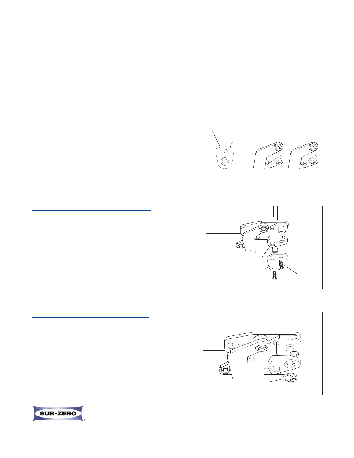
PROCEDURE FOR SINGLE DOOR MODELS
1. With door closed, remove the two 5/16 x 3/4 cap screw
from below the bottom cabinet hinge stiffener plate.
Remove stiffener plate and spacer bushing
(See Figure D).
2. Slide door stop onto hinge pin. The stub on the door
stop fits into the hole in the cabinet hinge
(See IMPORTANT NOTE and Figure D).
3. Retain door stop by replacing stiffener plate, spacer
bushing, and cap screws (See Figure D).
PROCEDURE FOR SIDE-BY-SIDE MODELS
1. With door closed, slide door stop up onto hinge pin.
The stub on the door stop fits into the hole on the
cabinet hinge (See IMPORTANT NOTE and Figure E).
2. Retain door stop by pushing E-Ring into groove at the
end of the hinge pin. Make sure that the E-Ring
is clipped securely into the groove of the hinge pin
(See Figure E).
Page 1 of 2
E Ring
90° Door
Stop
Figure E
IMPORTANT NOTE: This stop will limit door opening to
approximately 90
o
, and actually has two positions for slightly
more or less travel. If door travel is slightly too far, simply
flip the stop over, this is the same procedure if the travel is
slightly short (See Figures A, B, & C).
90° Door
Stop
Figure D
Cap
Screws
Stiffener
Plate
Setting 1
(More Opening)
Setting 2
(Less Opening)
Figure A
Figure B
Figure C
Less Opening
More Opening
Page 2
3752920 / Rev I / April, 2012
DS105 / IDS105 - 105oDoor Stop
NOTE: See Service Parts Price List for applicable 400, 500 and 600 Series units.
Page 2 of 2
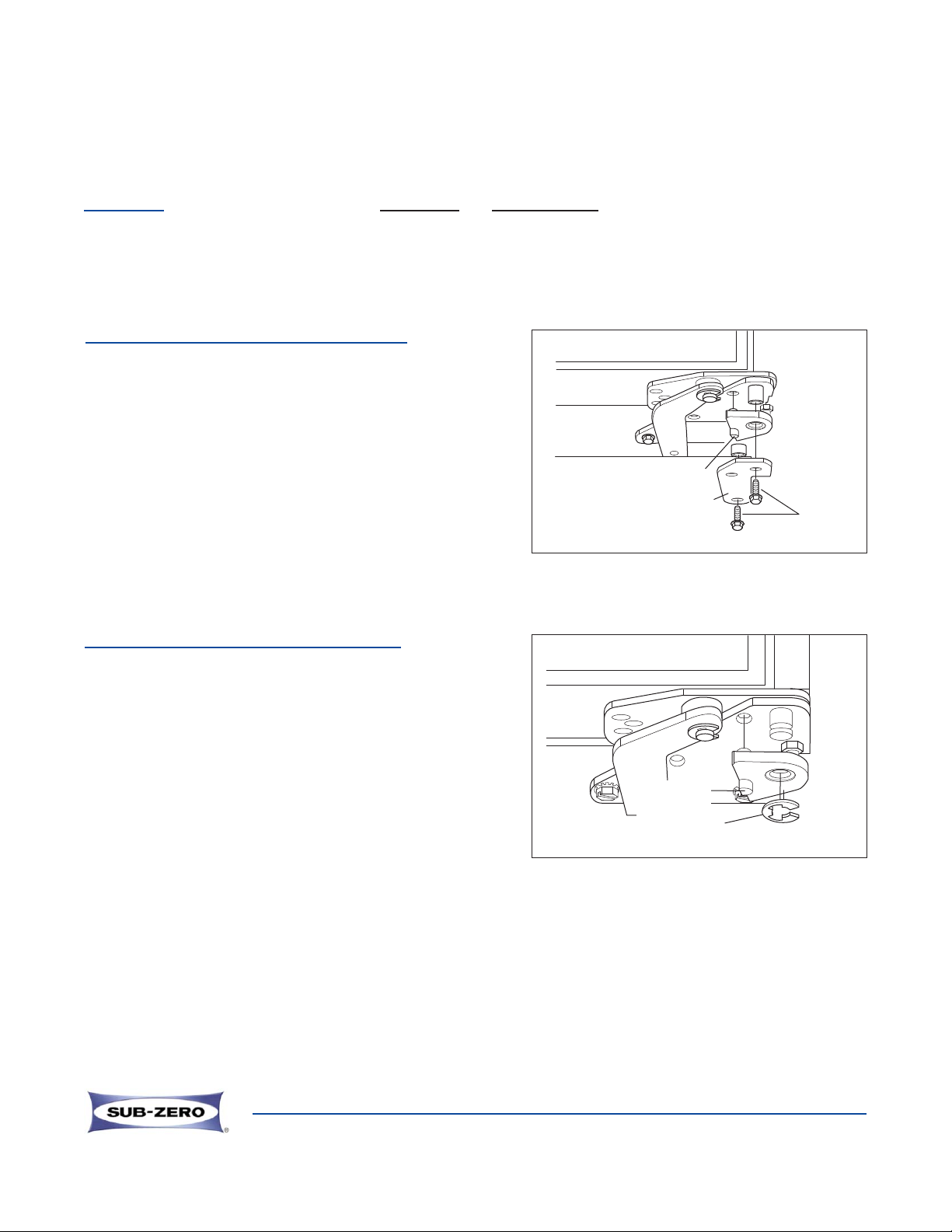
E Ring
105° Door
Stop
105° Door
Stop
Cap
Screws
Stiffener
Plate
CONTAINS QUANTITY DESCRIPTION
1 Door Stop
2 E-Rings (1 extra)
1 Instruction
PROCEDURE FOR SINGLE DOOR MODELS
1. With door closed, remove the two 5/16 x 3/4 cap screws
from below the bottom cabinet hinge stiffener plate.
Remove stiffener plate and spacer bushing
(See Figure 1).
2. Slide door stop onto hinge pin. The stub on the door stop
fits into the hole in the cabinet hinge (See Figure 1).
3. Retain door stop by replacing stiffener plate, spacer
bushing, and cap screws (See Figure 1).
Figure 1
Figure 2
PROCEDURE FOR SIDE-BY-SIDE MODELS
1. With door closed, slide door stop up onto hinge pin. The
stub on the door stop fits into the hole on the cabinet
hinge (See Figure 2).
2. Retain door stop by pushing E-Ring into groove at
the end of the hinge pin. Make sure that the E-ring is
clipped securely into the groove of the hinge pin
(See Figure 2).
 Loading...