

Page 1

Designer Series
Undercounter Refrigeration
Installation Guide
SPECIFICATIONS, INSTALLATION,
AND MORE
Page 2

Designer Series Undercounter Refrigeration
Contents
3 Designer Series Undercounter Refrigeration
4 Opening Dimensions
5 Electrical Requirements
6 Plumbing Requirements
6 Preparation
7 Anti-Tip Bracket
7 90° Door Stop
8 Placement
8 Alignment
9 Water Line
10 Door Panel
12 Panel Installation
14 Completion
Features and specifications are subject to change at any
time without notice. Visit subzero.com/specs for the most
up-to-date information.
Important Note
To ensure this product is installed and operated as safely
and eciently as possible, take note of the following types
of highlighted information throughout this guide:
IMPORTANT NOTE highlights information that is especially
important.
CAUTION indicates a situation where minor injury or product damage may occur if instructions are not followed.
WARNING states a hazard that may cause serious injury or
death if precautions are not followed.
IMPORTANT NOTE: Throughout this guide, dimensions in
parentheses are millimeters unless otherwise specified.
IMPORTANT NOTE: Save these instructions for the local
electrical inspector.
2 | Sub-Zero Customer Care 800.222.7820
Page 3

Designer Series Undercounter Refrigeration
Product Information
Important product information, including the model and
serial number, are listed on the product rating plate. The
rating plate is located inside the cabinet, in the upper left
area of the unit. Refer to the illustration below.
If service is necessary, contact Sub-Zero Factory Certified
Service with the model and serial number. For the name of
the nearest Sub-Zero Factory Certified Service or for questions regarding the installation, visit the Product Support
section of our website, subzero.com, or call Sub-Zero
Customer Care at 800-222-7820.
RATING PLATE
Rating plate location
subzero.com | 3
Page 4

Site Preparation
SIDE
NOTE:
Opening Dimensions
DESIGNER SERIES UNDERCOUNTER MODELS
24" (610)
OPENING
DEPTH
TOP VIEW
H
OPENING
HEIGHT
VIEW FRONT VIEW
31/2" (89) finished returns will be visible and should be finished to match cabinetry.
3
/4" (19)
31/2" (89)
FINISHED
RETURN
TYPICAL
OPENING WIDTH
31/2" (89)
FINISHED
RETURN
W
3
/4" (19)
TYPICAL
FILLER
The depth of each model is 23⁄" (587). Allow for panel
thickness when planning the finished opening depth. A
minimum 3⁄"
(89) finished return is required on all sides of
the opening. Framed cabinets require additional finished
filler material behind the face frame for a proper installation. Refer to the illustration.
DUAL INSTALLATION
If two units are installed side by side, a dual installation kit
may be required. Installations without a custom filler strip
require a dual installation kit. If a dual installation kit is not
specified, a 2"
(51) filler strip is recommended between the
units. Dual installations without a filler strip can only be
accomplished using two units with opposite hinges. Refer
to the illustrations below.
Dual installation kits are available through an authorized
Sub-Zero dealer. For local dealer information, visit the find
a showroom section of our website, subzero.com. For
questions regarding the installation, call Sub-Zero Customer Care at 800-222-7820.
DUAL OPENING WIDTH W
Two 24" Models 48" (1219)
Dual installation kit required.
W
FRAMELESS
CABINETRY
W
FRAMED
CABINETRY
OPENING DIMENSIONS W H
24" Model 24" (610) 34⁄" (876)
4 | Sub-Zero Customer Care 800.222.7820
WITHOUT FILLER STRIP
Opposite hinges
FILLER STRIP
Same side hinges
Page 5

Site Preparation
Electrical Requirements
Installation must comply with all applicable electrical
codes.
The electrical supply must be located within the shaded
area shown in the illustration below. A separate circuit
servicing only this appliance is required.
IMPORTANT NOTE: For indoor models, a ground fault circuit interrupter (GFCI) is not recommended and may cause
interruption of operation.
For the outdoor model, a ground fault circuit interrupter
(GFCI) is required to reduce the risk of electrical shock.
The electrical outlet must be positioned with the grounding prong to the right of the thinner blades.
RIGHT SIDE
OF OPENING
(76)
1
/4" (6)
3"
9"
(229)
4"
(102)
FLOOR
Electrical supply location
CAUTION
The outlet must be checked by a qualified electrician
to be sure it is wired with the correct polarity. Verify
the outlet is properly grounded.
WARNING
If the supply cord is damaged, it must be replaced by
the manufacturer, its service agent or similarly qualified persons in order to avoid a hazard.
WARNING
Do not locate multiple portable socket-outlets,
power strip, or portable power supplies at the rear of
the appliance.
WARNING
Do not use an extension cord, two-prong adapter, or
remove the power cord ground prong.
ELECTRICAL REQUIREMENTS
Electrical Supply 115 VAC, 60 Hz
Service 15 amp dedicated circuit
Receptacle 3-prong grounding-type
subzero.com | 5
Page 6

Site Preparation
Plumbing Requirements
MODEL DEU2450CI
Installation must comply with all applicable plumbing
codes.
For ease of installation, recess the water shut o into the
wall or place it in an adjacent cabinet. Locate the water
supply line within the shaded area shown in the illustration below. Connect the water supply line to the house
supply with an easily accessible shut-o valve. Do not use
self-piercing valves.
An in-line filter is required when water conditions have a
high sediment content.
A reverse osmosis system can be used provided there is
constant water pressure of 35–120 psi
to the unit at all times. A copper line is not recommended
for this application.
PLUMBING REQUIREMENTS
Water Supply Line ⁄" OD copper, braided
Water Pressure 35–120 psi (2.4–8.3 bar)
Excess Water Line for Connection 5' (1.5 m)
(2.4–8.3 bar) supplied
stainless steel, or PEX tubing
Preparation
Uncrate the unit and inspect for damage. Remove and
recycle packing materials. Do not discard the kickplate,
anti-tip bracket, and hardware.
Remove the kickplate by extracting the two mounting
screws. Refer to the illustration below.
SCREW
Kickplate removal
LEFT SIDE
OF OPENING
3"
(76)
AREA EXTENDS
FORWARD ON FLOOR
Water supply location
6 | Sub-Zero Customer Care 800.222.7820
9"
(229)
1
/2" (13)
4"
(102)
Page 7

Site Preparation
Anti-Tip Bracket
WARNING
To prevent the unit from tipping forward, the anti-tip
bracket must be installed.
The anti-tip bracket should be attached to the wall behind
the unit with the bracket flange located ⁄"
top of the unit. Refer to the illustration below. Failure to
properly position the anti-tip bracket will prevent proper
engagement.
ANTI-TIP
BRACKET
1
/4" (6)
Anti-tip bracket
(6) above the
90° Door Stop
The door stop pins provided with the unit limit the door
swing to 90°.
IMPORTANT NOTE: If a 90° door opening is desired, the
pins must be installed prior to installing the unit into the
opening.
To install, open the door to approximately 80°. Insert one
hinge pin into each hinge. Refer to the illustration below.
DOOR STOP PIN
90° door stop
subzero.com | 7
Page 8

Installation
Placement
CAUTION
Before moving the unit into position, secure the door
closed and protect any finished flooring.
WARNING
When positioning the appliance, ensure the supply
cord is not trapped or damaged.
Use an appliance dolly to move the unit near the opening.
If the unit has been on its back or side, it must stand
upright for a minimum of 24 hours before connecting
power.
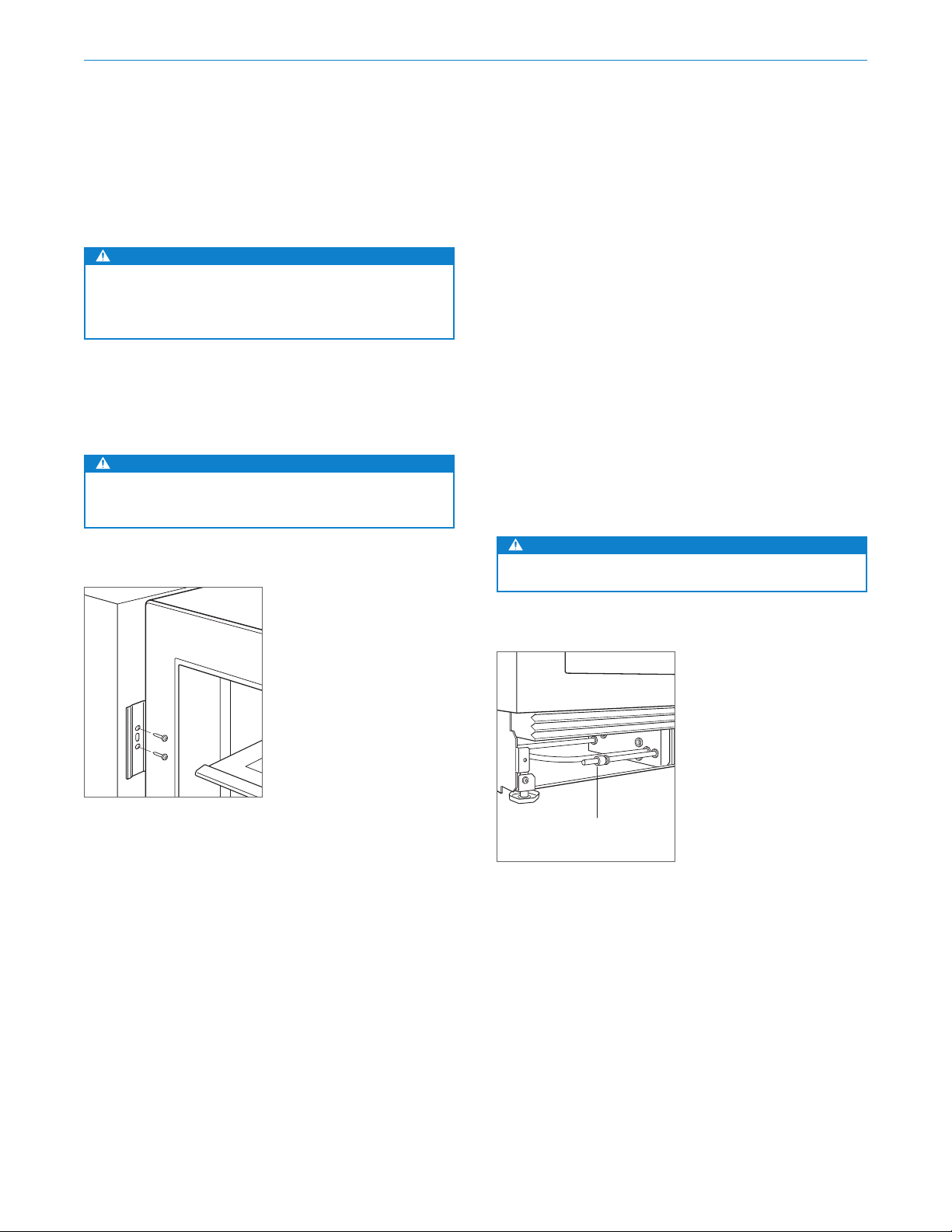
Plug the power cord into the grounded outlet. For model
DEU2450CI, insert the water supply line into the hole on
the back of the unit. Refer to the illustration below. Pull the
excess water line forward as the unit is slid into the opening. Verify the anti-tip bracket is properly engaged.
Alignment
LEVELING
Once the unit is in position, rotate the front legs clockwise
to raise and counterclockwise to lower. Rear height adjustment can be made from the front. Using a Phillips drive,
turn clockwise to raise the unit or counterclockwise to
lower. Use the lowest torque setting when using a power
drill. Do not turn the leveling legs by hand. Refer to the
illustration below.
When the unit is properly leveled, door adjustments are
less likely to be necessary.
IMPORTANT NOTE: Level the unit to the floor, not the
surrounding cabinetry. This could aect the operation of
the unit, such as door closing.
WARNING
To reduce the possibility of the unit tipping forward,
the front leveling legs must be in contact with the
floor.
HOLE FOR
WATER LINE
BACK OF UNIT
Water line (model DEU2450CI)
8 | Sub-Zero Customer Care 800.222.7820
ADJUSTMENT
Leveling
FRONT
REAR
ADJUSTMENT
Page 9
Installation
Alignment
ANCHORING
CAUTION
If using a power drill to predrill holes or install
screws, verify the drill chuck does not contact the
units face frame.
Adjust the depth of the unit to fit flush with the surrounding cabinetry. Allow for panel thickness. Once aligned,
verify the door opens properly, then install screws in each
bracket.
WARNING
To avoid a hazard due to instability of the appliance,
it must be fixed in accordance with the instructions.
Water Line
MODEL DEU2450CI
Under the unit, ⁄" plastic tubing is connected to the unit
with a preassembled ⁄" compression connection. The
water line fitting connection kit, provided with the unit,
contains a ⁄" compression union fitting for connection to
the household water line.
Purge the water line prior to final connection to the unit.
This will remove any debris that may be present in the
tubing from installing the new water line. Connect the
plastic tubing from the unit to the house water supply line
with the fitting connection kit provided. Refer to the
illustration below. Check all water line fittings for leaks.
IMPORTANT NOTE: Water lines cannot be exposed to
freezing temperatures.
WARNING
Connect to potable water supply only.
Anchoring
WATER LINE
CONNECTION
Water line connection
subzero.com | 9
Page 10

Door Panel
Stainless Steel Panel
Stainless steel panels are available through an authorized
Sub-Zero dealer. Stainless steel panels include a stainless
steel kickplate cover. The outdoor model requires the use
of a Sub-Zero stainless steel outdoor accessory panel. For
local dealer information, visit the find a showroom section
of our website, subzero.com.
Minimum ⁄"
(3) reveals are required.
Custom Panel
A custom door panel and handle hardware must be
installed.
(16) minimum to ⁄" (19) maximum thick panel is
A ⁄"
required. The panel cannot exceed the maximum panel
weight indicated in the chart below. The depth of each
model is 23⁄"
ning the finished opening depth.
Minimum ⁄"
PANEL WEIGHT MAX
24" Model 22 lb (10 kg)
Finish all sides of the custom panel. They will be visible
when the door is open.
A D-style handle is recommended. Locate the door handle
near the edge of the panel opposite the hinge and centered top to bottom. Stainless steel tubular and pro handles
are avail able through an authorized Sub-Zero dealer. For
local dealer information, visit the find a showroom section
of our website, subzero.com.
(587). Allow for panel thickness when plan-
(3) reveals are required.
10 | Sub-Zero Customer Care 800.222.7820
Page 11

Door Panel
Custom Panel
TOE KICK CLEARANCE
The height of the toe kick area can extend beyond the
typical toe kick height, provided it does not exceed the
dimensions in the illustration below. For questions
regarding the installation, call Sub-Zero Customer Care
at 800-222-7820.
341/2" (876)
TYPICAL
PRODUCT
HEIGHT
DOOR
PANEL
2" (51)
TO
41/2" (114)
FROM
FLOOR
HINGE
33/8" (86)*
DECORATIVE
KICKPLATE
HEIGHT
(587)
231/8"
TO BACK OF UNIT
DECORATIVE KICKPLATE
CANNOT EXTEND
BEYOND THIS
POINT
11/8" (29)
KICKPLATE
ADJUSTMENT
MAXIMUM DOOR OPENING
As the panel width and/or depth increases, so does the
potential for panel interference. Interference may be
minimized by using the 90° door stop.
DOOR OPEN
MAXIMUM 115°
3
/8" (10)
1
(3) REVEAL
/8"
ADJACENT
CABINETRY
DOOR
OPEN
90°
DOOR CLOSED
3
/4" (19) PANEL
31/2" (89)
MAX DEPTH
*Not included. Dimension will vary as the product height increases or decreases
from the typical product height.
Toe kick clearance (side view)
Maximum door opening (top view)
subzero.com | 11
Page 12

Panel Installation
Panel Installation
DOOR PANEL INSTALLATION
Typical panel dimensions are based on an 34⁄"
ished height with ⁄"
(3) reveals. Placement of the template
(876) fin-
must be adjusted for panels exceeding the typical dimensions.
Place the panel face down on a protected work surface.
Position the template flush with the top and sides of the
panel. Verify the correct side of the template is being used,
then mark and drill holes. Refer to the illustration below.
TOP OF DOOR PANEL
TOP OF DOOR PANEL
RIGHT SIDE DOOR PANEL
LEFT SIDE DOOR PANEL
Door panel template
Use a Torx drive to partially insert a #8 x ⁄" screw into the
second hole from the top on each side of the panel. The
screws should be approximately ⁄"
(4) proud of the panel
and will support the weight of the panel during installation.
Align the support screws on the back of the panel with the
slotted holes on both door mounting brackets. Refer to
the illustration below. Opening the door slightly may help
with alignment. Once the panel is supported by the screws,
partially insert a #8 x ⁄" screw into the second hole from
the bottom on each side of the panel, but do not tighten.
CAUTION
As reveals between cabinetry and the unit decrease,
severe finger pinching can occur while the door is
closing.
BACK OF PANEL
12 | Sub-Zero Customer Care 800.222.7820
Door panel mounting
Page 13

Panel Installation
Panel Installation
DOOR PANEL ADJUSTMENT
Close the door. Make any necessary adjustments to align
the panel and reveals.
For side-to-side adjustment, move the panel side to side,
then install and tighten all mounting screws.
For up-and-down and in-and-out adjustments, slightly
loosen the bracket screws. Depending on the level of
adjustment required, it may be helpful to loosen all of the
bracket screws which will allow for maximum adjustment.
Once the bracket screws are loosened, use a wrench to
rotate the cams to make adjustments. After the adjustments have been made, tighten all bracket screws. Refer to
the illustrations below.
IN-AND-OUT
CAM
BRACKET
SCREWS
In-and-out adjustment
BRACKET
SCREWS
UP-AND-DOWN
CAM
Up-and-down adjustment
subzero.com | 13
Page 14

Installation
Completion
DOOR TRIM INSTALLATION
After the door panel has been adjusted, install the decorative side trim to the door. To install, start at the top
and align the trim with the front and rear flanges on the
bracket, then snap into place by pushing the trim toward
the back of the panel. Once the top is secure, continue the
installation downward until the remaining trim is completely secure. Refer to the illustration below.
SIDE TRIM INSTALLATION
Install the decorative trim strip to the handle side of the
unit. The side trim snaps over the brackets attached to the
handle side of the unit. Refer to the illustration below.
KICKPLATE INSTALLATION
The kickplate must be removable for service. The floor
cannot interfere with removal. Finger-tighten the adjustment bracket nuts. Refer to the illustration below. Make
in-and-out adjustments, then wrench-tighten the bracket
nuts. Install the kickplate with the provided screws.
A decorative kickplate can be attached to the factoryinstalled kickplate. The three rows of vented louvers
cannot be covered. A decorative kickplate cannot be
attached to the outdoor model.
To install a decorative kickplate, remove the paper backing
from the magnets and attach the decorative kickplate to
the magnets. The magnets allow the decorative kickplate
to be removed if necessary.
Door side trim
14 | Sub-Zero Customer Care 800.222.7820
Unit side trim
KICKPLATE
ADJUSTMENT
Kickplate adjustment
MAGNET
SCREW
Kickplate installation
Page 15

Installation
Completion
WARNING
Follow all city and state laws when storing, recycling,
or discarding unused refrigerators and freezers.
Sub-Zero, Sub-Zero & Design, Sub-Zero & Snowflake Design, Dual Refrigeration, The Living Kitchen, Great American Kitchens The Fine Art of Kitchen Design, Wolf, Wolf &
Design, Wolf Gourmet, W & Design, red colored knobs, Cove, and Cove & Design are registered trademarks and service marks of Sub-Zero Group, Inc. and its subsidiaries.
All other trademarks are property of their respective owners in the United States and other countries.
subzero.com | 15
Page 16

Refrigeración bajo mostrador de la Serie de Diseño
Contenido
3 Refrigeración bajo mostrador de la Serie de Diseño
4 Dimensiones de abertura
5 Requisitos eléctricos
6 Requisitos de plomería
6 Preparación
7 Soporte antivuelco
7 Tope para puerta a 90°
8 Colocación
8 Alineación
9 Línea de agua
10 Panel de la puerta
12 Instalación del panel
14 Finalización
Las características y especificaciones están sujetas a
cambios sin previo aviso. Visite subzero.com/specs para
obtener la información más actualizada.
Aviso importante
Para garantizar que este producto se instale y opere de
la forma más segura y eficiente posible, tome nota de los
siguientes tipos de información resaltada en este manual:
AVISO IMPORTANTE señala la información que es
especialmente importante.
PRECAUCIÓN indica una situación en la que se pueden
sufrir heridas leves o provocar daños al producto si no se
siguen las instrucciones.
ADVERTENCIA indica peligro de que se produzcan heridas
graves o incluso la muerte si no se siguen las precauciones.
AVISO IMPORTANTE: En toda esta guía, las dimensiones
entre paréntesis son milímetros, a menos que se
especifique lo contrario.
AVISO IMPORTANTE: Guarde estas instrucciones para el
inspector eléctrico local.
2 | Atención al cliente de Sub-Zero 800.222.7820
Page 17

Refrigeración bajo mostrador de la Serie de Diseño
Información del producto
La información importante del producto, incluidos el
modelo y el número de serie de la unidad, se encuentra
en la placa de datos del producto. La placa de datos
se encuentra dentro del gabinete, en el área superior
izquierda de la unidad. Consulte la siguiente ilustración.
Si necesita servicio, póngase en contacto con el centro
de servicio autorizado de Sub-Zero y tenga a la mano el
modelo y número de serie de la máquina. Para obtener
los datos del centro de servicio autorizado de Sub-Zero
más cercano o si tiene preguntas acerca de la instalación,
visite la sección de soporte técnico en nuestra página de
Internet subzero.com o llame a la línea de atención al
cliente de Sub-Zero al 800-222-7820.
PLACA DE DATOS
Ubicación de la placa de datos
subzero.com | 3
Page 18

Preparación del sitio
VIST
NOTA: Los tubos de retorno de
ter
Dimensiones de abertura
MODELOS BAJO MOSTRADOR
PROFUNDIDAD DE
LA ABERTURA
24" (610)
DE
VISTA SUPERIOR
ANCHO DE LA
TUBO DE
RETORNO
31/2" (89)
DE
W
ABERTURA
GABINETE
CON MARCO
ALTURA DE LA
ABERTURA
H
A LATERAL VISTA FRONTAL
minar para que se ajusten a los gabinetes.
TUBO DE
RETORNO
31/2" (89)
DE
CON ACABADOS
W
GABINETES
SIN MARCO
31/2" (89) con acabados se podrán ver y se deben
TÍPICO
3
/4" (19)
DE
CON ACABADOS
La profundidad de cada modelo es de 23⁄" (587). Para
determinar la profundidad de la abertura ya con acabados,
considere el grosor del panel. Se necesita un tubo de
retorno de 3⁄"
(89) con acabados en todos los lados de la
abertura. Los gabinetes con marco necesitan material de
relleno de acabado detrás del marco frontal para lograr
una instalación adecuada. Consulte la ilustración.
INSTALACIÓN DOBLE
Si se instalan dos unidades lado a lado, puede ser
necesario un kit de instalación doble. Las instalaciones
sin una tira de relleno personalizada requieren un kit de
instalación doble. Si el uso de un kit de instalación doble
W
no está especificado, se recomienda utilizar una tira de
relleno de 2"
(51) entre las unidades. Las instalaciones
dobles sin una tira de relleno solo se pueden realizar
cuando se utilizan dos unidades con bisagras opuestas.
Revise las siguientes ilustraciones.
Los kits de instalación doble están disponibles a través
de un distribuidor autorizado de Sub-Zero. Para obtener
más información acerca de los distribuidores locales,
consulte la sección “encuentre una sala de exhibición” en
nuestra página web subzero.com. Para preguntas sobre
TÍPICO
3
/4" (19)
DE
RELLENO
la instalación, comuníquese con la línea de atención al
cliente de Sub-Zero al 800-222-7820.
ANCHURA DE ABERTURA DOBLE W
Dos modelos de 24" 48" (1219)
Se requiere kit de instalación doble.
DIMENSIONES DE ABERTURA W H
Modelo de 24" 24" (610) 34⁄" (876)
4 | Atención al cliente de Sub-Zero 800.222.7820
SIN TIRA DE RELLENO
Bisagras opuestas
TIRA DE RELLENO
Bisagras en el mismo lado
Page 19

Preparación del sitio
Requisitos eléctricos
La instalación debe cumplir con todos los códigos
eléctricos vigentes.
El suministro eléctrico debe colocarse dentro del área
sombreada que se muestra en la siguiente ilustración.
Se necesita un circuito independiente que le suministre
electricidad únicamente a este electrodoméstico.
AVISO IMPORTANTE: Para los modelos internos, no es
recomendable utilizar un interruptor circuito de fallos de
conexión a tierra (Ground Fault Circuit Interrupter, GFCI),
ya que puede interrumpir el funcionamiento de la unidad.
Para los modelos externos, es necesario instalar un
interruptor de circuito de fallos de conexión a tierra (GFCI)
para reducir el riesgo de descarga eléctrica.
El tomacorriente eléctrico debe colocarse de tal forma que
la clavija con conexión a tierra quede a la derecha de las
aspas más delgadas.
LADO DERECHO
DE LA ABERTURA
(76)
1
/4" (6)
3"
9"
(229)
4"
(102)
SUELO
Ubicación del suministro
eléctrico
PRECAUCIÓN
Un electricista calificado debe revisar el
tomacorriente para asegurarse de que la conexión
del cableado se haya realizado con la polaridad
correcta. Compruebe que el tomacorriente esté
debidamente conectado a tierra.
ADVERTENCIA
Si el cable de alimentación está dañado, debe ser
reemplazado por el fabricante, su agente de servicio
o personas calificadas de manera similar para evitar
un peligro.
ADVERTENCIA
No coloque múltiples tomas de corriente, enchufe
múltiple o suministros eléctricos portátiles en la
parte posterior del electrodoméstico.
ADVERTENCIA
No use un cable de extensión, adaptador de dos
clavijas ni retire la clavija con conexión a tierra del
cable de corriente.
REQUISITOS ELÉCTRICOS
Suministro eléctrico 115 V CA, 60 Hz
Servicio Circuito dedicado de 15 amperes
Receptáculo Conexión a tierra de 3 clavijas
subzero.com | 5
Page 20

Preparación del sitio
Requisitos de plomería
MODELO DEU2450CI
La instalación debe cumplir con todos los códigos de
plomería vigentes.
Para facilitar la instalación, empotre en la pared la
válvula de cierre de agua o colóquela en un gabinete
adjunto. Localice la línea de suministro de agua en la
zona sombreada que se muestra en la ilustración a
continuación. Conecte la línea de suministro de agua al
suministro de la casa con una válvula de cierre de fácil
acceso. No utilice válvulas autoperforantes.
Se requiere un filtro en línea cuando las condiciones del
agua tienen un alto contenido de sedimentos.
Se puede utilizar un sistema de ósmosis inversa siempre
y cuando la presión del agua que llegue a la unidad se
mantenga de forma constante entre 35 y 120 psi (de 2.4
a 8.3 bares) en todo momento. No es recomendable usar
tuberías de cobre para esta aplicación.
REQUISITOS DE PLOMERÍA
Tuberías de suministro de agua Tubería de cobre, trenzada de
acero inoxidable o PEX de ⁄"
de diámetro exterior
Presión del agua De 35 a 120 psi (de 2.8 a
8.3bares)
Tubería de exceso de agua para
la conexión
5' (1.5 m)
Preparación
Desembale la unidad e inspeccione si tiene algún daño.
Retire y recicle los materiales de embalaje. No deseche el
zócalo, el soporte antivuelco ni las piezas de montaje.
Para quitar el zócalo extraiga los dos tornillos para
montaje. Consulte la siguiente ilustración.
TORNILLO
Extracción del zócalo
LADO IZQUIERDO
DE LA ABERTURA
3"
(76)
EL ÁREA SE EXTIENDE
Ubicación del suministro de
agua
6 | Atención al cliente de Sub-Zero 800.222.7820
9"
(229)
EN EL SUELO
1
/2" (13)
4"
(102)
Page 21

Preparación del sitio
Soporte antivuelco
ADVERTENCIA
Para evitar que la unidad se vuelque hacia el frente,
debe instalarse el soporte antivuelco.
El soporte antivuelco debe sujetarse a la pared detrás
de la unidad con la pestaña del soporte ubicada ⁄"
por arriba de la parte superior de la unidad. Consulte la
siguiente ilustración. No colocar correctamente el soporte
antivuelco impedirá que la unidad quede bien enganchada.
SOPORTE
ANTIVUELCO
1
/4" (6)
(6)
Tope para puerta a 90°
Los pasadores del tope de la puerta proporcionados con la
unidad limitarán el giro de la puerta a 90°.
AVISO IMPORTANTE: Si se desea tener una abertura de
puerta de 90°, se deben instalar los pasadores antes de
instalar la unidad en la abertura.
Para instalar, abra la puerta a aproximadamente 80°.
Inserte un pasador de bisagra en cada bisagra. Consulte
la siguiente ilustración.
PASADOR DEL TOPE
DE LA PUERTA
Soporte antivuelco
Tope para puerta a 90°
subzero.com | 7
Page 22

Instalación
Colocación
PRECAUCIÓN
Antes de mover la unidad a su posición, asegúrese de
que la puerta esté cerrada y proteja cualquier suelo
con acabado.
ADVERTENCIA
Cuando coloque el electrodoméstico, asegúrese de que
el cable de alimentación no esté atrapado ni dañado.
Use una plataforma rodante para mover la unidad cerca de
la abertura.
Si la unidad ha estado o está acostada o de lado, debe
ponerla de pie y dejarla así durante un mínimo de 24 horas
antes de conectarla al suministro eléctrico.
Enchufe el cable de alimentación en la toma de tierra.
Para el modelo DEU2450CI, inserte la línea de suministro
de agua en el orificio en la parte posterior de la unidad.
Consulte la siguiente ilustración. Tire de la línea de exceso
de agua hacia adelante mientras la unidad se desliza por
la abertura. Verifique que el soporte antivuelco esté bien
colocado.
Alineación
NIVELACIÓN
Una vez que la unidad esté en su lugar, gire las patas
frontales en sentido de las agujas del reloj para elevar y en
sentido contrario a las agujas del reloj para bajar. El ajuste
de la altura de la parte posterior se puede realizar desde
la parte delantera. Con un destornillador Phillips, gire en
sentido de las manecillas del reloj para levantar la unidad o
en sentido opuesto de las manecillas del reloj para bajarla.
Utilice la velocidad más baja de torsión cuando utilice un
taladro eléctrico. No ajuste las patas niveladoras con la
mano. Consulte la siguiente ilustración.
Cuando la unidad esté bien nivelada, será menos probable
que tenga que ajustar las puertas.
AVISO IMPORTANTE: Nivele la unidad con el suelo, no
con los gabinetes que la rodean. Esto podría afectar el
funcionamiento de la unidad, por ejemplo, el cerrado de
la puerta.
ADVERTENCIA
Para reducir la posibilidad de que la unidad se
vuelque hacia adelante, las patas niveladoras
delanteras deben estar en contacto con el suelo.
ORIFICIO PARA LA
LÍNEA DE AGUA
PARTE POSTERIOR DE LA UNIDAD
Línea de agua (modelo
DEU2450CI)
8 | Atención al cliente de Sub-Zero 800.222.7820
AJUSTE
FRONTAL
Nivelación
AJUSTE DE LA
PARTE TRASERA
Page 23

Instalación
Alineación
ANCLAJE
PRECAUCIÓN
Si va a utilizar un taladro eléctrico para hacer orificios
o instalar tornillos, verifique que el portabrocas no
entre en contacto con el marco de la cara de la unidad.
Ajuste la profundidad de la unidad para que quede al ras
con los gabinetes que la rodean. Hay que tener en cuenta
el grosor del panel. Una vez alineado, verifique que la
puerta se abre correctamente, luego instale los tornillos
en cada soporte.
ADVERTENCIA
Para evitar un peligro debido a la inestabilidad del
electrodoméstico, se debe fijar este de acuerdo con
las instrucciones.
Línea de agua
MODELO DEU2450CI
Debajo de la unidad, un tubo de plástico de ⁄ "está
conectado a la unidad con una conexión de compresión
de ⁄" preensamblada. El kit para instalar la conexión
de la línea de agua, que viene con la unidad, contiene
un accesorio para unión de compresión de ⁄" para
conectarlo a la toma de agua doméstica.
Purgue la línea de agua antes de hacer la conexión final
a la unidad. Esto eliminará cualquier residuo que pueda
haber quedado en la tubería al instalar la nueva línea
de agua. Conecte el tubo de plástico de la unidad al
suministro de agua doméstico con el kit de instalación de
la conexión que viene con la unidad. Consulte la siguiente
ilustración. Revise todos los accesorios de la línea de agua
para detectar fugas.
AVISO IMPORTANTE: Las líneas de agua no pueden
quedar expuestas a temperaturas de congelación.
ADVERTENCIA
Conecte solo al suministro de agua potable.
Anclaje
CONEXIÓN DE LA
LÍNEA DE AGUA
Conexión de la línea de agua
subzero.com | 9
Page 24

Panel de la puerta
Panel de acero inoxidable.
Están disponibles paneles de acero inoxidable con los
distribuidores autorizados Sub-Zero. El modelo externo
requiere que se utilicen paneles accesorios externos
de acero inoxidable de Sub-Zero. Para obtener más
información acerca de los distribuidores locales, consulte
la sección “encuentre una sala de exhibición” en nuestra
página web subzero.com.
Se requiere un mínimo de margen de ⁄"
(3).
Panel personalizado
Deben instalarse paneles de puerta personalizados y
herrajes de manijas.
Se requiere un panel de grosor mínimo de ⁄"
un máximo de ⁄"
máximo peso del panel indicado en la tabla siguiente.
La profundidad de cada modelo es de 23⁄"
determinar la profundidad de la abertura ya con acabados,
considere el grosor del panel.
Se requiere un mínimo de margen de ⁄"
PESO DEL PANEL MÁX
Modelo de 24" 22 lb (10 kg)
Aplique el acabado a todos los lados de los paneles
personalizados. Estos serán visibles con la puerta abierta.
Se recomienda usar manijas estilo D. Ubique las manijas de
las puertas cerca del borde del panel opuesto a la bisagra
y centre entre los extremos superior e inferior. Están
disponibles manijas tubulares y pro de acero inoxidable
con los distribuidores autorizados Sub-Zero. Para obtener
más información acerca de los distribuidores locales,
consulte la sección “encuentre una sala de exhibición” en
nuestra página web subzero.com.
(19). El panel no puede exceder el
(16) a
(587). Para
(3).
10 | Atención al cliente de Sub-Zero 800.222.7820
Page 25

Panel de la puerta
Panel personalizado
ESPACIO DEL ZÓCALO
La altura de la zona del zócalo puede ser mayor que
la altura típica, siempre y cuando no se excedan las
dimensiones de la ilustración siguiente. Para preguntas
sobre la instalación, comuníquese con la línea de atención
al cliente de Sub-Zero al 800-222-7820.
341/2" (876)
ALTURA
TÍPICA DEL
PRODUCTO
PANEL
DE LA
PUERTA
41/2" (114)
EL SUELO
2" (51)
A
DESDE
BISAGRA
33/8" (86)*
ALTURA DEL
ZÓCALO
DECORATIVO
PARTE POSTERIOR
(587)
231/8"
EN LA
DE LA UNIDAD
ZÓCALO DECORATIVO
NO SE PUEDE EXTENDER
MÁS ALLÁ DE ESTO
PUNTO
11/8" (29)
AJUSTE DEL
ZÓCALO
ABERTURA MÁXIMA DE LA PUERTA
A medida que el ancho o la profundidad del panel
aumenta, también lo hace el potencial de interferencia del
panel. Se puede minimizar la interferencia al usar un tope
para puerta a 90°.
PUERTA ABIERTA
A MÁXIMO 115°
3
/8" (10)
MÁRGENES DE
GABINETES
ADJUNTOS
1
/8" (3)
PUERTA
ABIERTA
90°
A
PANEL DE LA PUERTA
CERRADA
3
/4" (19)
31/2" (89)
PROFUNDIDAD MÁX.
*No incluido. La dimensión variará a medida que la altura del producto aumente
o disminuya con respecto a la altura típica del producto.
Separación del zócalo (vista lateral)
Abertura de la puerta a máximo (vista superior)
subzero.com | 11
Page 26

Instalación de los paneles
Instalación de los paneles
INSTALACIÓN DEL PANEL DE LA PUERTA
Las dimensiones típicas del panel están basadas en una
altura terminada de 34⁄"
(876) con márgenes de ⁄" (3). La
colocación de la plantilla se debe ajustar para paneles que
exceden las dimensiones típicas.
Coloque el panel boca abajo sobre una superficie de
trabajo protegida. Coloque la plantilla a ras con la parte
superior y los lados del panel. Compruebe que está usando
el lado correcto de la plantilla, luego marque y taladre los
orificios. Consulte la siguiente ilustración.
PARTE SUPERIOR DEL
PANEL DE LA PUERTA
TOP OF DOOR PANEL
RIGHT SIDE DOOR PANEL
LEFT SIDE DOOR PANEL
Plantilla del panel de la puerta
Utilice el destornillador Torx para insertar parcialmente
un tornillo #8 x ⁄" en el segundo orificio desde la parte
superior en cada lado del panel. Los tornillos deben
sobresalir aproximadamente ⁄"
(4) del panel y soportar el
peso del panel durante la instalación.
Alinee los tornillos de soporte en la parte posterior del
panel con los agujeros ranurados en los dos soportes de
montaje de la puerta. Consulte la siguiente ilustración.
Abrir la puerta un poco puede ayudar con la alineación.
Una vez que el panel esté soportado por los tornillos,
inserte parcialmente un tornillo #8 x ⁄" en el segundo
orificio desde la parte inferior en cada lado del panel, pero
no lo apriete.
PRECAUCIÓN
Mientras más disminuyan los márgenes entre los
gabinetes y la unidad, al cerrase la puerta se pueden
pellizcar fuertemente los dedos.
PARTE POSTERIOR
DEL PANEL
12 | Atención al cliente de Sub-Zero 800.222.7820
Montaje del panel de la puerta
Page 27

Instalación de los paneles
Instalación de los paneles
AJUSTE DEL PANEL DE LA PUERTA
Cierre la puerta. Haga cualquier ajuste necesario para
alinear el panel y los márgenes.
Para el ajuste de lado a lado, mueva el panel de lado a
lado, luego instale y apriete todos los tornillos de montaje.
Para los ajustes de arriba y hacia abajo, y hacia adentro y hacia
afuera, afloje un poco los tornillos del soporte. Dependiendo
del nivel de ajuste requerido, puede ser útil aflojar todos los
tornillos del soporte lo que permitirá un ajuste máximo. Una
vez que ha aflojado los tornillos del soporte, use una llave
hexagonal para girar las levas para realizar los ajustes. Después
de realizar los ajustes, apriete todos los tornillos del soporte.
Revise las siguientes ilustraciones.
LEVA HACIA
ADENTRO Y
HACIA AFUERA
TORNILLOS
PARA EL
SOPORTE
Ajuste hacia adentro y hacia
afuera
TORNILLOS
PARA EL
SOPORTE
LEVA HACIA
ARRIBA Y
HACIA ABAJO
Ajuste hacia arriba y hacia abajo
subzero.com | 13
Page 28

Instalación
Finalización
INSTALACIÓN DEL RIBETE DE LA PUERTA
Una vez que el panel de la puerta haya sido ajustado,
instale el lado decorativo del ribete en la puerta. Para
instalarlo, comience en la parte superior alinee el ribete
con las bridas frontal y posterior en el soporte y colóquelo
a presión en su lugar, empujando el ribete hacia la parte
posterior del panel. Una vez que la parte superior esté
asegurada, siga la instalación hacia abajo hasta que el
ribete restante esté completamente asegurado. Consulte la
siguiente ilustración.
INSTALACIÓN DEL RIBETE LATERAL
Instale la tira de ribete decorativo en el lado de la manija
de la unidad. El ribete lateral se abrocha sobre el soporte
unido al lado de la manija de la unidad. Consulte la
siguiente ilustración.
INSTALACIÓN DEL ZÓCALO
El zócalo debe ser desmontable para sacarlo cuando sea
necesario hacerle servicio a la máquina. El suelo no debe
interferir al desmontarlo. Apriete con los dedos las tuercas
del soporte de ajuste. Consulte la siguiente ilustración.
Haga ajustes hacia adentro y hacia afuera, luego apriete
con llave las tuercas del soporte. Instale el zócalo con los
tornillos proporcionados.
Se puede colocar un zócalo decorativa a el zócalo
instalada de fábrica. Las tres filas de rejillas de ventilación
no pueden ser cubiertas. No se puede sujetar un zócalo
decorativo al modelo externo.
Para instalar un zócalo decorativo, retire el papel protector
de los imanes y adhiera el zócalo decorativo a los imanes.
Los imanes permiten retirar el zócalo decorativo si
fuese necesario.
Ribete del lado de la puerta
14 | Atención al cliente de Sub-Zero 800.222.7820
Ribete del lado de la unidad
Ajuste del zócalo
AJUSTE
DEL ZÓCALO
TORNILLO
IMÁN
Instalación del zócalo
Page 29

Instalación
Finalización
ADVERTENCIA
Siga todas las leyes estatales y locales para
almacenar, reciclar o desechar los refrigeradores y
congeladores no utilizados.
Sub-Zero, Sub-Zero & Design, Sub-Zero & Snowflake Design, Dual Refrigeration, The Living Kitchen, Great American Kitchens The Fine Art of Kitchen Design, Wolf, Wolf &
Design, Wolf Gourmet, W & Design, perillas de color rojo, Cove, and Cove & Design son marcas registradas y marcas de servicio de Sub-Zero Group, Inc. y sus asociados.
Todas las demás marcas registradas son propiedad de sus dueños respectivos en los Estados Unidos y otros países.
subzero.com | 15
Page 30

Réfrigération sous le comptoir série Concepteur
Table des matières
3 Réfrigération sous le comptoir série Concepteur
4 Dimensions de l’ouverture
5 Exigences électriques
6 Exigences de plomberie
6 Préparation
7 Installation du support antibasculement
7 Butée de porte de 90°
8 Emplacement
8 Alignement
9 Conduite d’alimentation en eau
10 Panneau de porte
12 Installation du panneau
14 Achèvement
Les caractéristiques et les spécifications peuvent être
modifiées en tout temps sans préavis. Visitez subzero.com/
specs pour obtenir les renseignements les plus récents.
Remarque importante
Pour s’assurer que ce produit est installé et utilisé en toute
sécurité et aussi ecacement que possible, prenez note
des types de renseignement mis en évidence tout au long
de ce guide :
REMARQUE IMPORTANTE met en évidence des
renseignements qui sont particulièrement importants.
MISE EN GARDE indique une situation où une blessure
mineure ou des dommages au produit peuvent se produire
si les directives ne sont pas respectées.
AVERTISSEMENT décrit un danger qui peut causer une
blessure grave ou la mort si les précautions ne sont
pas respectées.
REMARQUE IMPORTANTE : Tout au long de ce guide, les
dimensions entre parenthèses sont en millimètres à moins
d’indication contraire.
REMARQUE IMPORTANTE : Conservez ces directives pour
l’inspecteur en électricité local.
2 | Service à la clientèle de Sub-Zero 800.222.7820
Page 31

Réfrigération sous le comptoir série Concepteur
Renseignements sur le produit
Des renseignements importants sur le produit, y compris
les numéros de modèle et de série, se trouvent sur la
plaque signalétique du produit. La plaque signalétique est
située à l’intérieur de l’armoire dans la zone supérieure
gauche de l’unité. Reportez-vous à l’illustration ci-dessous.
Si vous avez besoin de service, communiquez avec le
service Sub-Zero certifié par l’usine avec les numéros
de modèle et de série. Pour obtenir le nom du centre
de service Sub-Zero certifié par l’usine le plus près de
chez vous ou si vous avez des questions concernant
l’installation, consultez la section Assistance produits de
notre site Web, subzero.com, ou appelez le service à la
clientèle de Sub-Zero au 800-222-7820.
PLAQUE SIGNALÉTIQUE
Emplacement de la plaque
signalétique
subzero.com | 3
Page 32

Préparation du site
VUE DE PR
REMARQUE : Les retours finis de
finis pour s’agencer aux ar
Dimensions de l’ouverture
MODÈLES SOUS LE COMPTOIR
PROFONDEUR
D’OUVERTURE
24 po (610)
DE
HAUTEUR DE
L’OUVERTURE
H
OFIL VUE DE FACE
31/2 po (89) seront visibles et doivent être
moires.
TYPIQUE
3
/4 po (19)
RETOUR FINI
31/2 po (89)
DE
DE
VUE DE DESSUS
L’OUVERTURE
RETOUR FINI
31/2 po (89)
DE
LARGEUR DE
W
TYPIQUE
DE
3
/4 po (19)
FILLER
La profondeur de chaque modèle est de 23⁄po (587).
Allouez de l’espace pour l’épaisseur du panneau durant
la planification de la profondeur de l’ouverture finie. Un
retour fini d’au moins 3½po
(89) est requis sur tous les
côtés de l’ouverture. Les armoires encadrées nécessitent
un matériau de remblayage supplémentaire derrière le
cadre avant pour obtenir une installation appropriée.
Reportez-vous à l’illustration.
INSTALLATION DOUBLE
Si deux unités sont installées côté à côte, une trousse
d’installation double pourra être requise. Les installations
sans languette de remplissage personnalisée nécessitent
une trousse d’installation double. Si une trousse d’installation
double n’est pas précisée, une languette de remplissage de
(51) est recommandée entre les unités. Les installations
2 po
doubles sans languette de remplissage ne peuvent être
réussies qu’en utilisant deux unités avec des charnières
opposées. Reportez-vous aux illustrations ci-dessous.
Les trousses d’installation double sont oertes par
les dépositaires Sub-Zero autorisés. Pour obtenir des
renseignements sur votre dépositaire local, visitez la
section salle d’exposition de notre site Web, subzero.
com. Si vous avez des questions au sujet de l’installation,
communiquez avec le service à la clientèle de SubZero au
800-222-7820.
W
DIMENSIONS
DE L’OUVERTURE
Modèle de 24 po 24po (610) 34½po (876)
4 | Service à la clientèle de Sub-Zero 800.222.7820
ARMOIRE
SANS CADRE
W
ARMOIRE
AVEC CADRE
W H
LARGEUR D’OUVERTURE DOUBLE W
Deux modèles de 24 po 48po (1219)
Trousse d’installation double requise.
SANS LANGUETTE DE REMPLISSAGE
Charnières opposées
LANGUETTE DE REMPLISSAGE
Charnières du même côté
Page 33

Préparation du site
Exigences électriques
L’installation doit se conformer à tous les codes
électriques applicables.
L’alimentation électrique doit se trouver à l’intérieur de la
zone ombragée indiquée dans l’illustration ci-dessous. Un
circuit séparé servant uniquement cet appareil est requis.
REMARQUE IMPORTANTE : Pour les modèles pour
l’intérieur, un disjoncteur de fuite de terre (GFCI) n’est pas
recommandé et peut interrompre le fonctionnement.
Pour le modèle pour l’extérieur, un disjoncteur de fuite
de terre (GFCI) est requis pour réduire le risque de
choc électrique.
La prise doit être placée de façon à ce que la broche
de mise à la terre se trouve à la droite des broches
plus minces.
CÔTÉ DROIT
DE L’OUVERTURE
9 po
(229)
4 po
(102)
PLANCHER
Emplacement de l’alimentation
électrique
3 po
(76)
1
/4 po (6)
MISE EN GARDE
La prise doit être vérifiée par un électricien
qualifié pour s’assurer qu’elle est câblée avec la
polarité appropriée. Assurez-vous que la prise est
correctement mise à la terre.
AVERTISSEMENT
Si le cordon d'alimentation est endommagé, il doit
être remplacé par le fabricant, son agent de service ou des personnes de qualification similaire afin
d'éviter tout danger.
AVERTISSEMENT
Ne placez pas des prises de courant portatives, une
rallonge multiprises ou des sources d’alimentation
portatives à l’arrière de l’appareil.
AVERTISSEMENT
N’utilisez pas une rallonge, un adaptateur à deux
broches et ne retirez pas la broche de mise à la terre
du cordon d’alimentation.
EXIGENCES ÉLECTRIQUES
Alimentation électrique 115 volts CA, 60 Hz
Service circuit dédié de 15 ampères
Prise Mise à la terre à trois broches
subzero.com | 5
Page 34

Préparation du site
Exigences de plomberie
MODÈLE DEU2450CI
L’installation doit se conformer à tous les codes de
plomberie applicables.
Pour faciliter l’installation, encastrez le robinet d’arrêt
de l’eau dans le mur ou installez-le dans une armoire
adjacente. Placez l’alimentation en eau dans la zone
ombragée indiquée dans l’illustration ci-dessous.
Connectez la conduite d'alimentation en eau à l'alimentation de la maison avec une vanne d'arrêt facilement
accessible. N'utilisez pas de valves auto-perforantes.
Un filtre en ligne est nécessaire lorsque les conditions de
l'eau ont une teneur élevée en sédiments.
Un système à osmose inverse peut être utilisé à condition
qu’il y ait une pression d’eau constante de 35 à 120 lb/po²
(2,4 à 8,3 bars) vers l’unité en tout temps. Une conduite en
cuivre n’est pas recommandée pour cette application.
EXIGENCES DE PLOMBERIE
Conduite d’alimentation en eau Tube PEX, en acier inoxydable
tressé ou en cuivre de ¼po
de diamètre extérieur
Pression d’eau 35-120 lb/po² (2,4-8,3 bars)
Conduite d’alimentation en eau
supplémentaire pour connexion
5 pi (1,5 m)
Préparation
Sortez l’unité de la boîte et examinez-la pour vous
assurer qu’elle n’est pas endommagée. Retirez et recyclez
les matériaux d’emballage. Ne jetez pas la plaque de
protection, le support antibasculement et la quincaillerie.
Retirez la plaque de protection en enlevant les deux vis de
montage. Reportez-vous à l’illustration ci-dessous.
VIS
Retrait de la plaque de
protection
CÔTÉ GAUCHE
DE L’OUVERTURE
3 po
LA ZONE SE PROLONGE DE
VERS L’AVANT SUR LE PLANCHER
Emplacement de l’alimentation
en eau
6 | Service à la clientèle de Sub-Zero 800.222.7820
(76)
9 po
(229)
4 po
(102)
1
/2 po (13)
Page 35

Préparation du site
Support antibasculement
AVERTISSEMENT
Pour empêcher l’unité de basculer vers l’avant, le
support antibasculement doit être installé.
Le support antibasculement doit être fixé au mur derrière
l’unité avec la bride du support située à une distance
de ⁄ po
Reportez-vous à l’illustration ci-dessous. Si le support
antibasculement n’est pas aligné adéquatement, il ne
s’enclenchera pas correctement.
1
(6) au-dessus de la partie supérieure de l’unité.
SUPPORT
ANTIBASCULEMENT
/4 po (6)
Butée de porte de 90°
Les goupilles de butée de porte fournies avec l’unité
limitent l’ouverture de la porte à 90°.
REMARQUE IMPORTANTE : Si vous souhaitez que la porte
s’ouvre à 90°, les goupilles doivent être installées avant de
placer l’unité dans l’ouverture.
Pour installer, ouvrez la porte à environ 80°. Insérez une
goupille de charnière dans chaque charnière. Reportezvous à l’illustration ci-dessous.
GOUPILLE D’ARRÊT
DE PORTE
Support antibasculement
Butée de porte de 90°
subzero.com | 7
Page 36

Installation
Mise en place
MISE EN GARDE
Avant de mettre l’unité en place, sécurisez la porte
en position fermée et protégez tout plancher fini.
AVERTISSEMENT
Lorsque vous placez l’appareil, vérifiez que le cordon
d’alimentation ne soit pas pris ou endommagé.
Utilisez un chariot à appareil pour déplacer l’unité près
de l’ouverture.
Si l’unité a été posée sur le dos ou le côté, elle doit être
mise debout pendant au moins 24 heures avant de
relier l’alimentation.
Branchez le cordon d'alimentation dans la prise mise à
la terre. Pour le modèle DEU2450CI, insérez la conduite
d'alimentation en eau dans le trou à l'arrière de l'unité.
Reportez-vous à l'illustration ci-dessous. Tirez la conduite
d'eau excédentaire vers l'avant lorsque l'unité est glissée
dans l'ouverture. Vérifiez que le support anti-bascule est
correctement engagé.
Alignement
NIVELLEMENT
Une fois l’unité en place, pivotez les pieds avant dans le
sens horaire pour la relever ou dans le sens antihoraire
pour l’abaisser. Le réglage de la hauteur arrière peut être
eectué à partir de l’avant. Au moyen d’un tournevis
cruciforme, tournez dans le sens horaire pour relever
l’unité ou dans le sens antihoraire pour l’abaisser. Utilisez
le réglage de couple le plus bas lorsque vous utilisez une
perceuse électrique. Ne tournez pas les pieds d’inclinaison
à la main. Reportez-vous à l’illustration ci-dessous.
Lorsque l’unité est correctement mise au niveau, des
réglages à la porte sont moins susceptibles d’être
nécessaires.
REMARQUE IMPORTANTE : Nivelez l’unité en fonction du
plancher, pas des armoires environnantes. Cela pourrait
aecter le fonctionnement de l’unité, comme la fermeture
de la porte.
AVERTISSEMENT
Afin de réduire le risque de basculement vers l’avant
de l’unité, les pieds de nivellement avant doivent être
en contact avec le sol.
TROU POUR
CONDUITE
D’ALIMENTATION
EN EAU
ARRIÈRE DE L’UNITÉ
Ligne d'eau (modèle DEU2450CI)
8 | Service à la clientèle de Sub-Zero 800.222.7820
RÉGLAGE
AVANT
Nivellement
RÉGLAGE
ARRIÈRE
Page 37

Installation
Alignement
ANCRAGE
MISE EN GARDE
Si vous utilisez une perceuse électrique pour prépercer des trous ou poser des vis, vérifiez que le
mandrin de la perceuse n’entre pas en contact avec
le cadre avant de l’unité.
Réglez la profondeur de l’unité afin qu’elle soit à égalité
avec les armoires adjacentes. Tenez compte de l’épaisseur
du panneau. Une fois alignée, vérifiez que les portes
s’ouvrent correctement, puis installez les vis dans
chaque support.
AVERTISSEMENT
Pour éviter tout danger associé à l’instabilité de
l’appareil, elle doit être corrigée conformément
aux directives.
Conduite d’alimentation en eau
MODÈLE DEU2450CI
Sous l'unité, un tube en plastique de ⁄ "est connecté
à l'unité avec une connexion de compression de ⁄"
préassemblée. La trousse de connexion du raccord de
la conduite d’alimentation en eau, fournie avec l’unité,
comprend un raccord d’union de compression de ⁄
(6) pour eectuer la connexion jusqu’à la conduite
po
d’alimentation en eau de la résidence.
Purgez la conduite d’alimentation en eau avant d’eectuer
la dernière connexion vers l’unité. Ceci éliminera tous les
débris qui pourraient se trouver dans la conduite suite à
l’installation de la nouvelle conduite d’alimentation en
eau. Reliez le tube en plastique de l’unité à la conduite
d’alimentation en eau de la résidence au moyen de la
trousse de connexion du raccord fournie. Reportez-vous à
l’illustration ci-dessous. Vérifiez que tous les raccords de la
conduite d’alimentation en eau n’aient pas de fuites.
REMARQUE IMPORTANTE : Les conduites d’alimentation
en eau ne doivent pas être exposées au gel.
AVERTISSEMENT
Reliez à une alimentation en eaupotable seulement.
Ancrage
CONNEXION DE LA CONDUITE
D’ALIMENTATION EN EAU
Connexion de la conduite
d’alimentation en eau
subzero.com | 9
Page 38

Panneau de porte
Panneau en acier inoxydable
Des panneaux en acier inoxydable sont oerts par les
dépositaires Sub-Zero autorisés. Le modèle pour l’extérieur
nécessite l’utilisation d’un panneau accessoire en acier
inoxydable pour l’extérieur de Sub-Zero. Pour obtenir
des renseignements sur votre dépositaire local, visitez la
section salle d’exposition de notre site Web, subzero.com.
Des jeux d’au moins ⁄po
(3) sont requis.
Panneau personnalisé
Un panneau de porte personnalisé et la quincaillerie de
poignée doivent être installés.
Un panneau mesurant un minimum de ⁄po
maximum de ⁄po
du panneau ne doit pas dépasser le poids de panneau
maximal indiqué dans le tableau ci-dessous. La profondeur
de chaque modèle est de 23⁄po
pour l’épaisseur du panneau durant la planification de la
profondeur de l’ouverture finie.
Des jeux d’au moins ⁄po
POIDS DU PANNEAU MAX.
Modèle de 24 po 22 lb (10 kg)
Finissez tous les côtés du panneau personnalisé. Ils seront
visibles lorsque la porte est ouverte.
Une poignée en forme de D est recommandée. Placez
la poignée de porte près du rebord du panneau opposé
à la charnière et au centre de haut en bas. Des poignées
tubulaires et professionnelles en acier inoxydable sont
oertes par les dépositaires Sub-Zero autorisés. Pour
obtenir des renseignements sur votre dépositaire local,
visitez la section salle d’exposition de notre site Web,
subzero.com.
(19) d’épaisseur est requis. Le poids
(587). Allouez de l’espace
(3) sont requis.
(16) et un
10 | Service à la clientèle de Sub-Zero 800.222.7820
Page 39

Panneau de porte
CHARNIÈRE
PANNEAU
DE
PORTE
231/8 po
(587)
VERS L’ARRIÈRE
DE L’UNITÉ
2 po (51)
À
41/2 po (114)
DU
PLANCHER
31/2 po (89)
PROFONDEUR MAX.
11/8 po (29)
RÉGLAGE DE
LA PLAQUE
DE PROTECTION
341/2 po (876)
HAUTEUR
TYPIQUE
DU PRODUIT
PLAQUE DE PROTECTION
DÉCORATIVE IMPOSSIBLE
DE PROLONGER AU DELÀ DE
ÇA POINT
33/8 po (86)*
HAUTEUR DE
LA PLAQUE
DE PROTECTION
DÉCORATIVE
*Non inclus. La dimension variera à mesure que la hauteur du produit augmente
ou diminue par rapport à la hauteur typique du produit.
Panneau personnalisé
DÉGAGEMENT DE LA PLAQUE DE BUTÉE
La hauteur de la zone de la plaque de butée peut se
prolonger au-delà de la hauteur typique de la plaque de
butée, à condition qu’elle ne dépasse pas les dimensions
dans l’illustration ci-dessous. Si vous avez des questions
au sujet de l’installation, communiquez avec le service à la
clientèle de Sub-Zero au 800-222-7820.
OUVERTURE MAXIMALE DE LA PORTE
L’augmentation de la largeur ou de la profondeur du
panneau augmente aussi la possibilité d’interférence du
panneau. L’interférence peut être minimisée en utilisant
une butée de porte de 90°.
OUVERTURE MAXIMALE
DE PORTE DE 115°
3
/8 po (10)
JEU DE
ARMOIRE
ADJACENTE
1
/8 po
OUVERTURE
DE
PORTE
DE
(3)
90°
PANNEAU DE PORTE
FERMÉE DE
3
/4 po (19)
Dégagement de la plaque de butée (vue latérale)
Ouverture maximale de la porte (vue de dessus)
subzero.com | 11
Page 40

Installation du panneau
Installation du panneau
INSTALLATION DU PANNEAU DE PORTE
Les dimensions typiques d’un panneau sont fondées
sur une hauteur finie de 34½ po
(3). La position du gabarit doit être ajustée pour les
⁄po
(876) avec des jeux de
panneaux qui dépassent les dimensions typiques.
Placez le panneau vers le bas sur une surface de travail
protégée. Placez le gabarit à égalité avec le haut et les
côtés du panneau. Assurez-vous d’utiliser le bon côté du
gabarit, puis marquez et percez les trous. Reportez-vous à
l’illustration ci-dessous.
HAUT DU PANNEAU DE PORTE
TOP OF DOOR PANEL
RIGHT SIDE DOOR PANEL
LEFT SIDE DOOR PANEL
Utilisez un entraînement Torx pour partiellement insérer
une vis n° 8 x ½ po dans le deuxième trou à partir du haut
de chaque côté du panneau. Les vis doivent dépasser le
panneau d’environ ⁄ po
(4) et soutiendront le poids du
panneau pendant l’installation.
Alignez les vis de soutien à l’arrière du panneau avec les
trous allongés sur les deux supports de montage de porte.
Reportez-vous à l’illustration ci-dessous. Le fait d’ouvrir la
porte légèrement peut aider à eectuer l’alignement. Une
fois le panneau soutenu par les vis, insérez partiellement
une vis n° 8 x ½ po dans le deuxième trou à partir du bas
de chaque côté du panneau, mais ne serrez pas.
MISE EN GARDE
Lorsque les jeux entre les armoires et l’unité
diminuent, il y a des risques de pincements graves
des doigts pendant la fermeture de la porte.
ARRIÈRE DU PANNEAU
Gabarit du panneau de porte
Montage du panneau de porte
12 | Service à la clientèle de Sub-Zero 800.222.7820
Page 41

Installation du panneau
Installation du panneau
RÉGLAGE DU PANNEAU DE LA PORTE
Fermez la porte. Eectuez les réglages nécessaires pour
aligner le panneau et les jeux.
Pour le réglage d’un côté à l’autre, déplacez le panneau
d’un côté à l’autre, puis installez et serrez toutes les vis
de montage.
Pour les réglages de haut en bas et vers l’intérieur ou
l’extérieur, desserrez légèrement les vis de support. Selon
le niveau de réglage requis, il pourra s’avérer utile de
desserrer toutes les vis de support pour permettre un
réglage maximal. Une fois les vis de support desserrées,
utilisez une clé pour pivoter les cames pour eectuer les
réglages. Une fois les réglages terminés, serrez toutes les
vis de support. Reportez-vous aux illustrations ci-dessous.
CAME
INTÉRIEUREXTÉRIEUR
VIS DE
SUPPORT
Réglage vers l’intérieur ou
l’extérieur
VIS DE
SUPPORT
CAME DE HAUT
EN BAS
Réglage de haut en bas
subzero.com | 13
Page 42

Installation
Achèvement
INSTALLATION DE LA GARNITURE DE PORTE
Une fois le panneau de porte bien ajusté, installez la
garniture décorative latérale sur la porte. Pour installer,
commencez par le haut et alignez la garniture avec les
brides avant et arrière du support, puis enclenchez en
place en poussant la garniture vers l’arrière du panneau.
Une fois la partie supérieure sécurisée, continuez
l’installation vers le bas jusqu’à ce que la garniture
restante soit complètement fixée. Reportez-vous à
l’illustration ci-dessous.
INSTALLATION DE LA GARNITURE LATÉRALE
Installez la bande de garniture décorative du côté de la
poignée de l’unité. La garniture latérale s’enclenche sur les
supports fixés sur le côté poignée de l’unité. Reportez-vous
à l’illustration ci-dessous.
INSTALLATION DE LA PLAQUE DE PROTECTION
La plaque de protection doit pouvoir être enlevée
pour toute réparation. Le plancher ne doit pas nuire à
l’enlèvement. Serrez manuellement les écrous de réglage
des supports. Reportez-vous à l’illustration ci-dessous.
Eectuez des réglages vers l’intérieur ou l’extérieur, puis
serrez les écrous de support avec une clé. Installez la
plaque de protection avec les vis fournies.
Une plaque de protection décorative peut être fixée à la
plaque de protection installée en usine. Les trois rangées
de persiennes ventilées ne doivent pas être couvertes. Une
plaque de protection décorative ne peut pas être fixée au
modèle pour l’extérieur.
Pour installer la plaque de protection décorative, retirez
l’endos en papier des aimants et fixez la plaque de
protection décorative aux aimants. Les aimants permettent
le retrait de la plaque de protection décorative si
nécessaire.
Garniture latérale de porte
14 | Service à la clientèle de Sub-Zero 800.222.7820
Garniture latérale de l’unité
RÉGLAGE DE LA PLAQUE
DE PROTECTION
Réglage de la plaque de
protection
AIMANT
VIS
Installation de la plaque de
protection
Page 43

Installation
Achèvement
AVERTISSEMENT
Respectez toutes les lois provinciales et locales lors
de l’entreposage, le recyclage ou l’élimination des
réfrigérateurs et des congélateurs non utilisés.
Sub-Zero, Sub-Zero & Design, Sub-Zero & Snowflake Design, Dual Refrigeration, The Living Kitchen, Great American Kitchens The Fine Art of Kitchen Design, Wolf, Wolf &
Design, Wolf Gourmet, W & Design, les boutons de couleur rouge, Cove et Cove & Design sont des marques déposées et de service de Sub-Zero Group, Inc. et ses filiales.
Toutes les autres marques de commerce appartiennent à leurs propriétaires respectifs aux États-Unis et dans d'autres pays.
subzero.com | 15
Page 44

SUB-ZERO, INC. P.O. BOX 44848 MADISON, WI 53744 SUBZERO.COM 800.222.7820
9042175 REV-A 9/2020
 Loading...