

Page 1

COLD ROOM CONTROLLER
USER MANUAL
www.ascontrols.com
INDIA
CRC-1001 / CRC-1001-C
Page 2
DESCRIPTION
PARAMETER
Introduction
Pg.
No.
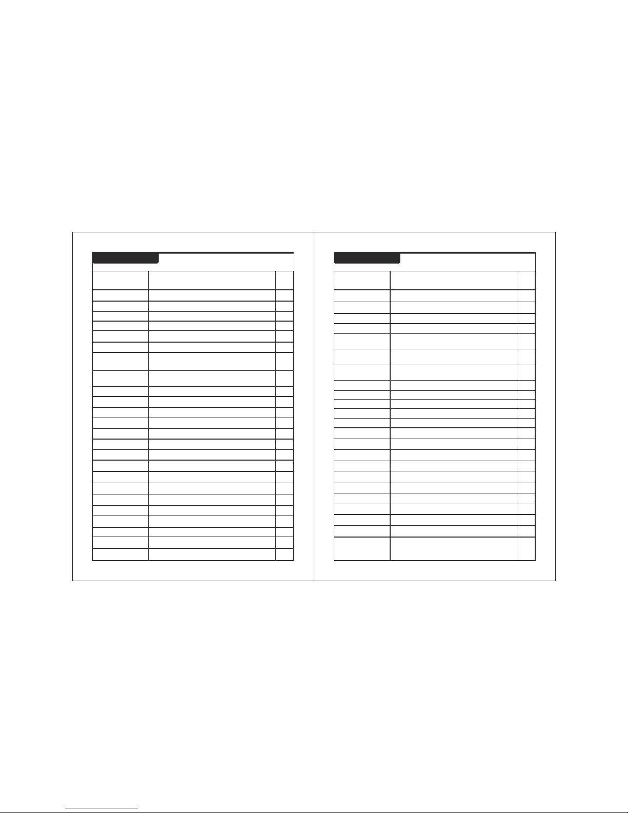
Index Index
01
DESCRIPTION
PARAMETER
Pg.
No.
02
Get to Know Your Controller
Parameter List
4
5
To set the cut-out point of the controller.
To set maximum allowable high temperature
limit.
SET POINT
P2
To set the Minimum Cooling Temperature.P3
To set the differential for compressor restart.
P4
To set probe calibration.
P5
To set time delay between relay restart time.
To set duration of defrost.
P6
P7
To set defrost frequency.
P8
To set power on defrost delay.
P9
To enable or disable Buzzer.
BUZ
To set under voltage limit.
UV
To set over voltage limit
OV
To set voltage differential.
V0
AL
Power on time delay for alarm.
5
6
6
8
8
10
7
7
7
8
9
9
9
10
To set time delay for voltage sensing.
V1
10
To set Over current limit.
OL
11
To set Under current limit.
UL
10-11
Key Introduction
5
To set Current sensing delay.
C2
11
D0
To enable or Disable HP sensing.
12
3
Main Programming Mode
5
Suggested wiring diagram for CRC-1001-C
To enable or disable LP sensing.
D1
To set fault sensing logic.
D2
To set LP sensing delay.
D3
To set reset mode for HP fault.
D4
To set Compressor Relay
status on Probe Failure.
E1
To set Evap fan status when
compressor is OFF.
E2
To set EVAP Fan operation at door open.
E4
End of programming.
EP
Technical Data
Suggested wiring diagram for CRC-1001
E3
To set Crankcase Heater operation
when compressor is OFF.
12
14
14
14
17
18
19
12
13
13
13
20
To set Display at defrosting.
E7
14
To set time delay to switch off the light .
LD
15
To change password.
PW
15
To set Unit ID. (For CRC-1001-C only)
Unit ID
16
Factory set parameter.
FS
15
Compressor run Hours.
CRH
15
Clear Compressor Run Hours.
CCRH
16
To activate Keypad Lock.
KEYPAD LOCK
16
Caution & Warranty
21
To enable/disable Power Switch.
PO
17
Page 3

The CRC-1001/CRC-1001-C are single set point cold room
controllers. The Sub-Zero CRC-1001/CRC-1001-C are
aesthetically superior versions of their predecessors.
A number of parameters are displayed alphanumerically to set
up the instrument for each specific function.
The CRC-1001/CRC-1001-C controller can be used for
several applications with a measuring range from
O O
-50.0 C to50.0 C.
The controller controls the defrost in the system based on time
based where the compressor is stopped. It is also possible to
select the interval between defrosts and a maximum time out
after which the defrost is interrupted.
There are safety features which include shutting down the
system incase of a fault from a pressure control or similar
device.
A series of “safety controls” (delay at start-up, minimum disable
time, minimum time between activation) protects the
compressors from close starts. In case of probe error or
temperature alarm, the instrument signals the event through
acoustic signal and by closing the relay contact. By pressing
the mute key, the buzzer is silenced.
Introduction
03 04
Get to Know Your Controller
Items included
NO.
1.
2.
3.
4.
QTY
ITEMS
CONTROLLER
CATALOGUE
NTC SENSOR 3 METER
1
1
1
3
6 X 25 SCREW
R
CRC-1001
FAULT LOG VOLT
Amp.
HP/LP
UL/OL UV/OV
E
RST
PRG
SET
AUX
Dot Matrix LED Display
LED
Indications
Lamp
Key
Reset
Key
Defrost
Key
Program Mode
Key
Up / Volt.
Key
Down / Amp.
Key
Set Key
Power ON/OFF
Key
Fault
Log Key
N
C
E
Y
G
S
R
T
E
O
M
P
E
Page 4
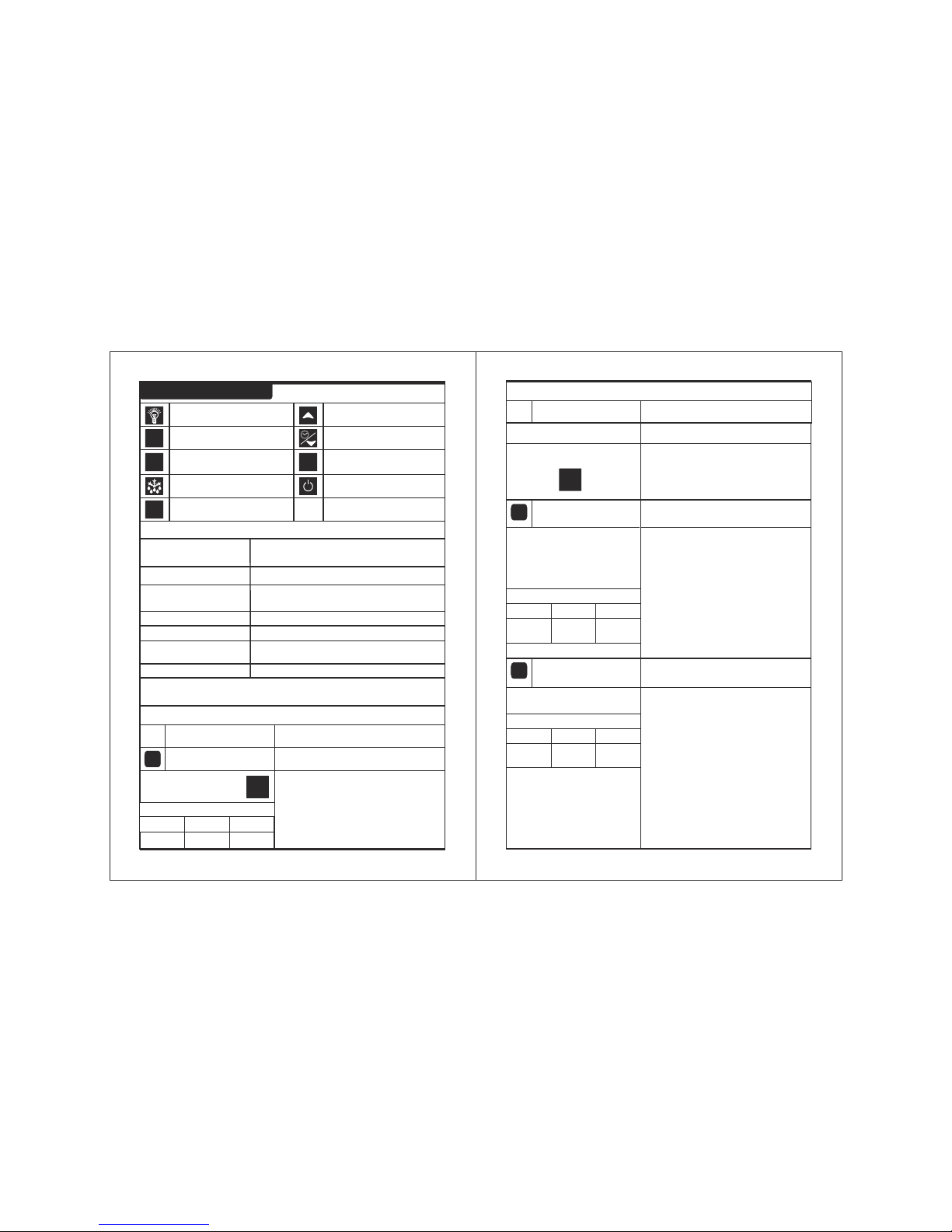
Key Introduction
Auxiliary/Fault Log Key
Alarm Reset Key
Defrost Key
RST
AUX
PRG
Program Key
Up/Volt Key
SET
Down/Amp. Key
Set Key
Power Key
Lamp ON/OFF Key
Press PRG Key to Enter Programming mode
/ ESC Key.
1> USER PROGRAM
MAIN SYSTEM PROGRAMMING MODE
Press AUX/FAULT LOG Key to View last
9 Fault Log.
3> FAULT LOG
05
SET POINT To set the cut-out point of the controller.
Display will change to set value.
The set point value can now be changed
by using the UP/DOWN key. After
desired value, press the SET key & you
will see “-- ” which confirms that the set
point has been stored in memory.
01
Press and hold SET key
for 2 seconds and
Release.
P3+0.5
P2-0.5
0.0ºC
SET
Min: MINIMUM Max : MAXIMUM
Fact. Set : FACTORY SETTING(DEFAULT)
Sr.
No.
Parameter setting method
Description of parameters and functions.
Parameter
Range
Min Max
Fact. Set
02
P2
Parameter
Function : To set maximum allowable
high temperature limit.
To change P2 parameter,
press the set key.
Use UP/DOWN key to set desired value.
Example : Setting this parameter
0
at 30.0 C will not allow the set point to go
0
above 30.0 C also if the temperature
0
reaches 30.0 C, the display will show HT
(High Temperature). The alarm will be
ON. But at power on till the AL delay is
over controller will not generate HT Alarm.
Once set at a particular value, this will
not allow the set point to go above this
value and below P3 setting.
03
P3
Parameter
Function : To set minimum allowable low
temperature limit.
Use UP/DOWN key to set desired value.
Example : Setting this parameter
0
at -30.0 C will not allow the set point to
0
go below -30.0 C also if the temperature
0
reaches -30.0 C, the display will show
LT (Low Temperature). The alarm will be
ON.
Once set at a particular value, this will
not allow the set point to go below this
value and above P2 setting.
To change parameter,
press the set key.
P3
Set Point
+0.5
50.0ºC 50.0ºC
-50.0ºC
Set Point
-0.5ºC
-50.0ºC
06
PRG
To set other parameter
Press & hold PRG key for
2 seconds
Display will show ‘P2’ and scroll the
description of the parameter.
To go to other parameters ,
use up / down keys.
Range
Min Max
Fact. Set
Sr.
No.
Parameter setting method
Description of parameters and functions.
Parameter
Range
Min Max
Fact. Set
Press RST Key to reset alarm relay & buzzer.
4> Mute
Press SET Key to Enter Set mode.
2> SET MODE
Press Defrost Key for manual defrost.
5> Manual Defrost
Press Down/Amp Key to see the compressor
current.
6> View Current
Press UP/Volt Key to see the voltage.
7> View Voltage
Page 5

07
Sr.
No.
Parameter setting method
Description of parameters and functions.
Parameter
P5
Parameter
Use UP/DOWN keys to set desired
value.
Example :
In time it may be possible that the
display may be offset by a degree or so.
To compensate for this error, you may
need to add or minus the degrees
required to achieve the correct
temperature.
The temperature on the
O
display is 28.0 C, whereas the actual
O
temperature is 30.0 C. You will need to
O
set this parameter to 2.0 C, which
means that once out of the programming
parameter, the display will show the
O O O
temperature 30.0 C (28.0 C + 2.0 C).
To change P5
press the set key.
parameter,
05
Function: To set probe calibration.
-10.0ºC 10.0ºC 0.0ºC
Range
Min Max
Fact. Set
P6
Parameter
Use UP/DOWN keys to set desired value.
Example :
This parameter is used to protect the fan
from restarting in a short period of time
and can be set between 0 to 20 minutes.
If this parameter is set at 3
minutes, the compressor will cut off at
the set temperature, but will not restart
for a minimum of 3 minutes, even if the
differential is achieved earlier. This
To change P6
press the set key.
parameter,
06
Function : To set time delay between
relay restart time.
1 Min 20 Min 3 Min
Range
Min Max
Fact. Set
Use UP/DOWN keys to set desired value.
Example(Cooling Mode) : If the set
0
point is set at 10.0 C and differential is
0
set at 2.0 C, then when the system
0
reaches 10.0 C, the comp. relay will
0
cutout. Since the differential is 2.0 C, the
0
comp. Relay will cutin at 12.0 C
0 0
(10.0 C + 2.0 C).
04
P4
Parameter
Function: To set the differential for
compressor restart.
To change P4
press the set key.
parameter,
0.5ºC 20.0ºC 2.0ºC
Range
Min Max
Fact. Set
08
Sr.
No.
Parameter setting method
Description of parameters and functions.
Parameter
P7
Parameter
07
Function : To set duration of defrost.
To change the P7 Parameter,
press the set key.
Use UP/DOWN keys to set desired value.
0 Min 99 Min 30 Min
Range
Min Max
Fact. Set
This is maximum amount of time allowed
for defrost. If set to 0, there will be no
defrost cycle
Example : If P7 is set to 30 Mins and
P8 parameter is set to 1 Hr. then after
every 1 Hr defrosting will take place for
30 mins. In defrosting Compressor ,
Evap Fan relay willl be OFF.
P8
Parameter
08
Function : To set defrost frequency.
To change the P8 Parameter,
press the set key.
Use UP/DOWN keys to set desired value.
1 Hrs 31 Hrs 6 Hrs
Range
Min Max
Fact. Set
This is the amount of time between two
defrost cycles.
Example : same as P7 parameter.
P9
Parameter
09
Function : To set power on defrost delay.
To change the P9 Parameter
parameter, press the set key.
Use UP/DOWN keys to set desired value.
0 Min 99 Min 30 Min
Range
Min Max
Fact. Set
This is the amount of time at power on
after which defrosting will take place
once.
Example : If P9 parameter is 30 mins
then at power after 30 mins defrosting
will take place once.
parameter is good to protect the life of
the compressor when there are power
fluctuations and the compressor is
switched off and on within a few seconds.
Page 6

Sr.
No.
Parameter setting method
Description of parameters and functions.
Parameter
Use UP/DOWN keys to set desired value.
ENB : Buzzer Enabled.
DIS : Buzzer Disabled.
10
BUZ
Parameter
Function: To enable or disable Buzzer.
To change BUZ
press the set key.
parameter,
DIS ENB ENB
Range
Min Max
Fact. Set
Use the UP/DOWN keys to get desired
value and press SET key.
11
AL
Parameter
Function: Power on time delay for alarm.
To change AL
press the set key.
parameter,
0 Min 99 Min 30 Min
Range
Min Max
Fact. Set
Use UP/DOWN keys to set desired
value.
Example : If this parameter is set to
180V then if the voltage is less than
180V it will show UV fault on display and
Compressor Relay will be off.
12
UV
Parameter
Function: To set under voltage limit.
To change UV
press the set key.
parameter,
180V (OV-10)V 180V
Range
Min Max
Fact. Set
Sr.
No.
Parameter setting method
Description of parameters and functions.
Parameter
OV
Parameter
13
Function : To set over voltage limit
To change the OV Parameter
parameter, press the set key.
Use UP/DOWN keys to set desired value.
(UV+5)V 260 240
Range
Min Max
Fact. Set
Example : If this parameter is set to
240V then if the voltage is above than
240V it will show OV fault on display
and Compressor Relay will be off.
V1
Parameter
15
Function : To set time delay for
voltage sensing.
To change the V1 Parameter
parameter, press the set key.
Use UP/DOWN keys to set desired value.
5 Sec 30 Sec 5 Sec
Range
Min Max
Fact. Set
Example : If V1 parameter is 5, then if
voltage fault condition occures and
stays continuously for 5 sec then only
fault is valid.
UL
Parameter
16
Function : To set Under current limit.
To change the UL Parameter
parameter, press the set key.
Use UP/DOWN keys to set desired value.
0.0A (OL-1.0)A 1.0A
Range
Min Max
Fact. Set
This parameter used to switch off the
compressor incase it draws lower
current than the set current.
V0
Parameter
14
Function : To set voltage differential.
To change the V0 Parameter
parameter, press the set key.
Use UP/DOWN keys to set desired value.
5V 50V 5V
Range
Min Max
Fact. Set
Example : If this parameter is set to 5V
then for OV fault when voltage is grater
than OV-5 then only this fault is cleared.
For UV fault then when the voltage is
greater than UV+5 then only UV fault
will be cleared.
09
10
Example : If you set this parameter to
20min, once the power is switch on, the
alarm for Ht/Lt will not activate for 20
minutes after the power is switched on.
This is most useful to avoid the nuisance
alarms when the ambient are high when
machine is switched on after long time.
Page 7

11
12
OL
Parameter
17
Function : To set Over current limit.
To change the OL parameter,
press the set key.
Use UP/DOWN keys to set desired
value.
This parameter used to switch off the
compressor incase it draws higher
current than the set current.
Example : If this parameter is set at
10.0A, the controller will trip compressor
if it draws more than 10.0A.Controller
will restart the compressor after the set
time delay. If after 3 retries within 1hour,
current drawn is still more than 10.0A,
the controller will trip the compressor on
fault and activate the respective alarm
relay. Also display will flash “OL”.
(UL+1.0)A 18.0A 10.0A
Range
Min Max
Fact. Set
Range
Min Max
Fact. Set
Use UP/DOWN keys to set desired value.
Example :
ENB = HP sensing is enabled.
DIS = HP sensing is disabled
If this parameter is set to
Setting this parameter to disable will
ignore HP fault for compressor. If this
parameter is set to Enable then controller
will detect HP trip.
To change the D0 parameter,
press the set key.
D0
Parameter
19
Function : To enable or Disable HP
sensing.
DIS
ENB
ENB
Range
Min Max
Fact. Set
To change the C2 parameter,
press the set key.
C2
Parameter
18
Function: To set Current sensing delay.
Use UP/DOWN keys to set desired
value.
Example : If C2 parameter is 1 Sec
then, any current fault will be valid only
when it exsists for more than 1 sec.
0 Sec 60 Sec 5 Sec
Range
Min Max
Fact. Set
Range
Min Max
Fact. Set
Sr.
No.
Parameter setting method
Description of parameters and functions.
Parameter
Sr.
No.
Parameter setting method
Description of parameters and functions.
Parameter
D2
Parameter
21
To change D2 parameter,
press the set key.
0V
230V
Function: To set fault sensing logic.
230V
Use UP/DOWN keys to set desired
value.
0v =
rip the
compressor.
230V =
rip the
compressor.
0V at HP/LP/AUX input will be
sensed as fault and t
230V at HP/LP/AUX input will be
sensed as fault and t
Range
Min
Max
Fact. Set
Example : If this parameter is set at
1.0A, the controller will trip compressor if
it draws less than 1.0A. Controller will
restart the compressor after the set time
delay. If after 3 retries within 1hour,
current drawn is still less than 1.0A, the
controller will trip the compressor on fault
and activate the respective alarm relay.
Also display will flash “UL”.
Use UP/DOWN keys to set desired
value.
Example:
If this parameter is set to
ENB = LP sensing is enabled.
DIS = LP sensing is disabled.
Setting this parameter to disable will
ignore LP fault for compressor. If this
parameter is set to Enable then controller
will detect LP trip.
To change D1
parameter, press the set key.
DIS
ENB
D1
Parameter
20
ENB
Function: To enable or disable LP
sensing.
Range
Min
Max
Fact. Set
Page 8

13
14
To change E1 parameter,
press the set key.
E1
Parameter
24
Range
Min Max
Fact. Set
Range
Min Max
Fact. Set
When set to
ON = Relay will stay ON.
CYC = Relay performs a duty cycle of
10 minutes ON and
4minutes OFF.
OFF = Relay will stay OFF.
ON OFF CYC
Function : To set Compressor Relay
status on Probe Failure.
Use UP/DOWN keys to set desired
value.
Sr.
No.
Parameter setting method
Description of parameters and functions.
Parameter
Sr.
No.
Parameter setting method
Description of parameters and functions.
Parameter
To change D4 parameter,
press the set key.
D4
Parameter
23
Function : To set reset mode for HP fault.
MAN
AUTO
MAN
Range
Min Max
Fact. Set
Range
Min Max
Fact. Set
Use UP/DOWN keys to set desired
value.
MAN = Manual Mode
AUTO = Auto mode
If this parameter set to “MAN” mode HP
fault will be cleared only after pressing
reset key for 2 seconds.
If this parameter is set to “AUTO” mode
HP fault will be cleared automatically
when it is healthy.
E7
Parameter
Use UP/DOWN keys to set desired
value.
TEMP = At defrosting temperature
will be dispalyed.
DEF = At Defrosting 'Defrost ON'
will scroll.
28
Function: To set Display at defrosting.
To change E7 parameter,
press the SET key.
TEMP DEF
TEMP
Range
Min Max
Fact. Set
Range
Min Max
Fact. Set
OFF
ON
ON
E3
Parameter
Use UP/DOWN keys to set desired
value.
OFF = Heater will stay Off.
ON = Heater will stay On.
at compressor off condition.
Crankcase
Crankcase
26
Function : To set Crankcase Heater
operation when compressor is OFF.
To change E3 parameter,
press the set key.
Range
Min Max
Fact. Set
Range
Min Max
Fact. Set
Use UP/DOWN keys to set desired
value.
OFF = Evap Fan will stay OFF.
ON = Evap Fan will stay ON.
at door open condition.
E4
Parameter
27
Function: To set EVAP Fan operation at
door open.
To change E4 parameter,
press the set key.
OFF ON ON
Range
Min Max
Fact. Set
Range
Min Max
Fact. Set
To change D3 parameter,
press the set key.
0 Sec
22
MinMin
Use UP/DOWN keys to set desired value.
Example : If this parameter is set at 30
seconds, the system will ignore low
pressure alarm for 30 sec from
compressor on. In this manner, a false
alarm can be avoided due to low
pressure at compressor start up.
180 Sec
30 Sec
D3
Parameter
Function : To set LP sensing delay.
Range
Max
Fact. Set
Range
Max
Fact. Set
E2
Parameter
25
Function : To set Evap fan status when
compressor is OFF.
Use UP/DOWN keys to set desired
value.
OFF = Evaporator Fan will stay OFF.
ON = Evaporator Fan will stay ON.
at compressor off condition.
To change E2 parameter,
press the set key.
OFF ON ON
Range
Min Max
Fact. Set
Range
Min Max
Fact. Set
Page 9

15
Sr.
No.
Parameter setting method
Description of parameters and functions.
Parameter
Example : If this parameter is set to 7
mins then, when light is switched on after
7 mins it will be switch off automatically.
0
9999
0
To change PW parameter,
press the SET key.
PW
Parameter
30
Function : To change password.
Use UP/DOWN key to change password.
User can enter into program
mode only if correct password is
entered. If the password is wrong it will
show ‘INVALID PASSWORD’.
Range
Min Max
Fact. Set
Range
Min Max
Fact. Set
To change CRH parameter,
press the SET key.
CRH
Parameter
32
Function: Compressor run Hours.
It will display compressor run hours. It's
a read only parameter.
LD
Parameter
Use UP/DOWN keys to set desired
value.
This parameter is used set the time
delay to automatically switch off the light.
If LD is set to 0 then this parameter is
disabled.
29
Function : To set time delay to switch off
the light .
To change LD parameter,
press the SET key.
0 Min 30 Min 7 Min
Range
Min Max
Fact. Set
Range
Min Max
Fact. Set
16
Sr.
No.
Parameter setting method
Description of parameters and functions.
Parameter
KEYPAD LOCK
34
To change Keypad Lock
parameter, press the set key.
NO YES NO
Function: To activate Keypad Lock.
This parameter can lock the keypad so
that tempering is not possible by bystanders.
NO - deactivates keypad lock.
YES - activates keypad lock.
When locked all parameters can only be
viewed, but not modified.
Range
Min Max
Fact. Set
Range
Min Max
Fact. Set
NO
YES
NO
To change CCRH parameter,
press the SET key.
CCRH
33
Function : Clear Compressor Run Hours.
If t his par ame ter is s et t o ‘YES ’
com pr ess or ru n ho ur s (CRH ) a re
cleared.
Range
Min Max
Fact. Set
Range
Min Max
Fact. Set
NO
YES
NO
To change FS parameter,
press the SET key.
FS
Parameter
Function : To restore default settings of
the controller.
Use UP/DOWN keys to set desired value.
When set to YES all parameters
are programmed to factory
values.
Useful to debug setting related
problems.
23
31
Range
Min Max
Fact. Set
Range
Min Max
Fact. Set
Unit ID
Parameter
This parameter is used to set the Unit ID of
the device.
35
Function: To set Unit ID.
(For CRC-1001-C only)
To change Unit ID
parameter, press the SET key.
1 240
1
Range
Min Max
Fact. Set
Range
Min Max
Fact. Set
Page 10

17
Sr.
No.
Parameter setting method
Description of parameters and functions.
Parameter
EP
Parameter
Once the SET key is pressed, the control
goes into the normal mode and displays
the temperature and all settings are
recorded.
37
Function: To end programming.
To end programming
parameter, press the set key.
Technical Data
18
Housing : ABS Plastic.
Front Cover : Red Ploycarbonate plastic.
Dimensions : Length 227mm, Width 200mm, Depth 93 mm
Mounting : Panel/Wall mounting with screws.
Connection : Screw terminal blocks.
2.5sq mm one wire/terminal only.
Display : 0.56”, 5X7 Dot Matrix LED display.
Data Storage : Non-Volatile EEPROM Memory.
Power Input (Options) : 230Vac +/-10%, 50-60Hz, Other on request.
0 0
Operating Temp : 5 C to 50 C(non-condensing).
0 0
Storage temp : -20 C to 70 C(non-condensing).
Output :
Compressor Relay : 20A/250Vac.
Evap Relay : 10(3)A/250Vac.
Crankcase Heater : 8(2)A/250Vac.
Light Relay : 5A/250Vac.
Alarm Relay : 5A/250Vac.
Input : 1 NTC Probe.
0 0
Range : -50.0 C to 50.0 C.
0
Resolution : 0.1 C.
0
Accuracy : +/-1 C.
0 0
Probe Tolerance at 25 C : +/-0.3 C.
Alarm (Buzzer) : SZ-B75. 10V,10mA.
RS485 Connectivity : Modbus RTU Protocol
(for CRC-1001-C only) Baud Rate : 9600, N, 8, 1
Device ID : 1 (By Default)
<
Use UP/DOWN keys to get desired
value & press SET key to confirm.
DIS = Disable power switch
ENB = Enables power switch
Controller has power switch, which
if enable puts controller in active or
stand by state.
If press for 2 seconds controller will
go in stand by mode, display will
scroll message “STAND BY MODE”.
To again switch to ACTIVE WORKING
MODE, press power switch again for 2
seconds.
DIS
ENB
DIS
To change PO parameter,
press the SET key.
PO
Parameter
Function : To enable/disable Power
Switch.
23
36
Range
Min Max
Fact. Set
Range
Min Max
Fact. Set
Page 11

19
Suggested Wiring Diagram for CRC-1001
15 16
17
18 19
HP
LP
LP HP AUX
AUX
230V
N L
Caution : Wiring for 230Vac Load Only.
3
21
4
PHASE
NEUTRAL
5
6
7
8 9 10
11 12
13
14
NO NO NOC C C
COMP
Alarm 250 Vac
5Amax
CCH EVAP
NO C
LIGHT
NO C
ALARM
TEMP. DOOR
Light or Contact
5A Max
Compressor
or Contactor Coil
(250VAC, 20Amax)
CCH or Contactor Coil
(250VAC, 8(2)Amax)
Evap or Contactor Coil
(250VAC, 10(3)Amax)
20
Suggested wiring Diagram for CRC-1001-C
20
21 22
230V
N L
Caution : Wiring for 230Vac Load Only.
21
PHASE
NEUTRAL
12
13
14 17
18 19
NO C
COMP
Alarm 250 Vac
5Amax
3
4
NOC
CCH
5
6
NO C
EVAP
7
8 9 10
NO C
LIGHT
NO C
ALARM
HP
LP
LP HP AUX
AUX
TEMP. DOOR
Light or Contact
5A Max
15 16
RS485
- +
Compressor
or Contactor Coil
(250VAC, 20Amax)
CCH or Contactor Coil
(250VAC, 8(2)Amax)
Evap or Contactor Coil
(250VAC, Amax)10(3)
Page 12

21
WIRING : The probe and its corresponding wires should never be installed
in a conduit next to control or power supply lines. The electrical wiring
should be done as shown in the diagram. The power supply circuit should
be connected to a protection switch. The terminals admit wires of upto
2.5sq mm.
WARNING : Improper wiring may cause irreparable damage and personal
injury. Kindly ensure that wiring is done by qualified personnel only.
Maintenance : Cleaning : Clean the surface of the controller with a soft
moist cloth. Do not use abrasive detergents, petrol, alcohol or solvents.
Controller
Controller should be installed in a place protected by vibration, water and
corrosive gasses and where ambient temperature does not exceed the values
specified in the technical data.
Probe
To give a correct reading, the probe must be installed in a place protected from
thermal influences, which may affect the temperature to be controlled.
Caution
22
The information in this document is subject to change in order to improve
reliability, design or function without prior notice and does not represent a
commitment on the part of the company. In no event will the company be liable
for direct, indirect, special, incidental or consequential damage arising out of
the use or inability to use the product or documentation, even if advised of the
possibility of such damages. No part of this manual may be reproduced or
transmitted in any form or by any means without the prior written permission of
the company.
Notice
Disclaimer
Warranty
This manual & its contents remain the sole property of A.S.Controls Pvt.Ltd.,
India and shall not be reproduced or distributed without authorization. Although
great care has been taken in the preparations of this document, the company
or its vendors in no event will be liable for direct, indirect, special, incidental or
consequential damage arising out of the use or inability to use the product or
documentation, even if advised of the possibility of such damages. No part of
this manual may be reproduced or transmitted in any form or by any means
without the prior written permission of the company. A.S.Controls Pvt.Ltd.
reserves the right to make and changes or improvements without prior notice.
This product is warranted against defects in materials and workmanship for a
period of one year from the date of purchase. During the warranty period,
product determined by us to be defective in form or function will be repaired or,
at our option, replaced at no charge. This warranty does not apply if the product
has been damaged by accident, abuse, and misuse or as a result of service or
modification other than by the company. This warranty is in lieu of any other
warranty expressed or implied. In no event shall the company be held liable for
incidental or consequential damages, such as lost revenue or lost business
opportunity arising from the purchase of this product.
Page 13

INDIA
Ball Valves
Globe Valves
Hand Valves
Flow Switches
Solenoid Valves
OUR OTHER PRODUCTS
Cold Room Controller
Chiller Controller
Two Compressors Controller
Heating Controller
Humidity Controller
Pressure Controller
TM
04 / 18.06.13
 Loading...