

Page 1

Built-In Refrigeration Installation Guide
Page 2

BUILT-IN REFRIGERATION
Contents
3 Built-In Refrigeration
4 Opening Dimensions
8 Dual Installation
8 Electrical
9 Plumbing
9 Preparation
10 Anti-Tip Bracket
12 Placement
12 Water Line
13 Custom Panels
16 Alignment
17 Completion
Features and specications are subject to change at any
time without notice. Visit subzero.com/specs for the most
up-to-date information.
Important Note
To ensure this product is installed and operated as safely
and efciently as possible, take note of the following types
of highlighted information throughout this guide:
IMPORTANT NOTE highlights information that is especially
important.
CAUTION indicates a situation where minor injury or product
damage may occur if instructions are not followed.
WARNING states a hazard that may cause serious injury or
death if precautions are not followed.
IMPORTANT NOTE: Throughout this guide, dimensions in
parentheses are millimeters unless otherwise specied.
IMPORTANT NOTE: Save these instructions for the local
electrical inspector.
Page 3

BUILT-IN REFRIGERATION
Product Information
Important product information including the model and
serial number are listed on the product rating plate. The
rating plate is located at the top frame of the unit, inside the
door. Refer to the illustration below.
If service is necessary, contact Sub-Zero factory certied
service with the model and serial number. For the name
of the nearest Sub-Zero factory certied service or for
questions regarding the installation, visit the contact & support section of our website, subzero.com or call Sub-Zero
customer care at 800-222-7820.
RATING
PLATE
Tools and Materials
• Screwdrivers—standard and Phillips.
• Power drill.
• Drill bits (masonry bits required for concrete installation).
• Torx drives—T-10, 15 and 20.
• Standard Allen wrench set.
• Standard socket and wrench set.
• 2' and 4' levels.
• Tubing cutter.
1
• 3' of
• Saddle valve.
• Material to protect home, ooring and cabinetry during
/4" OD copper, braided stainless steel or PEX
tubing.
installation.
Rating plate location.
subzero.com | 3
Page 4

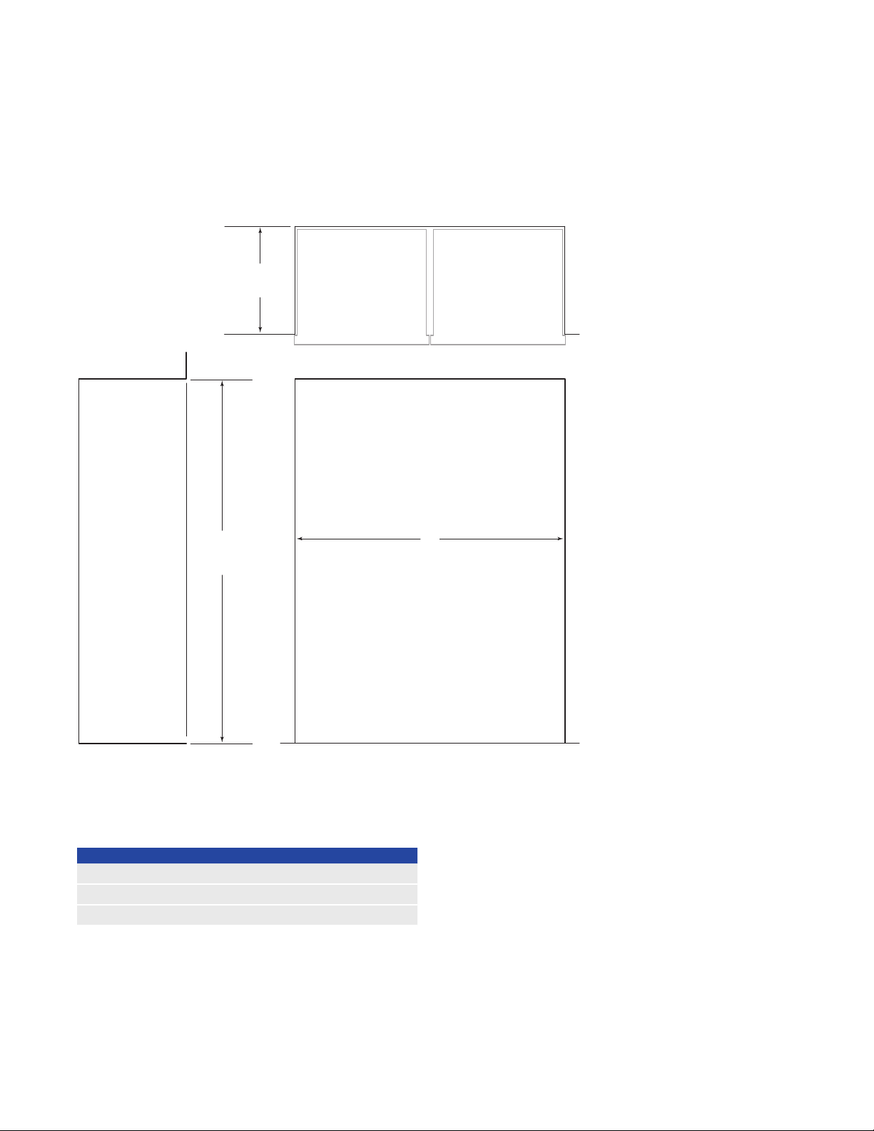
SITE PREPARATION
SIDE
Opening Dimensions
STANDARD INSTALLATION
24" (610)
OPENING
DEPTH
TOP VIEW
833/4"
(2127)
OPENING
HEIGHT
VIEW
NOTE: Shaded line represents profile of unit.
W
OPENING WIDTH
FRONT VIEW
OPENING WIDTH W
1
BI-36R, BI-36RG, BI-36F 35
/2" (902)
BI-30U, BI-30UG 291/2" (749)
BI-36U, BI-36UG, BI-36UFD 351/2" (902)
BI-36S 351/2" (902)
BI-42UFD 411/2" (1054)
BI-42S, BI-42SID, BI-42SD 411/2" (1054)
BI-48S, BI-48SID, BI-48SD 471/2" (1206)
If two units are installed side by side, refer to page 6.
4 | Sub-Zero Customer Care 800.222.7820
Page 5

SIDE
SITE PREPARATION
Opening Dimensions
FLUSH INSET INSTALLATION
263/16"
(665)
FLUSH
INSET
DEPTH
23/16"
(56)
TOP VIEW
FINISHED
CLEATS*
1
/4"
(6)
84"
(2134)
FLUSH
INSET
HEIGHT
VIEW
*3" (76) typical depth. Shaded areas will be visible and should be finished to match cabinetry.
NOTE: Shaded line represents profile of unit with
3
/4" (19) panel.
11/4"
(32)
FLUSH INSET WIDTH
FRONT VIEW
W
4" (102)
11/4"
(32)
3"
(76)*
TYPICAL
23/16"
(56)
FLUSH INSET WIDTH W
BI-36R, BI-36RG, BI-36F 38"
(965)
BI-30U, BI-30UG 32" (813)
BI-36U, BI-36UG, BI-36UFD 38" (965)
BI-36S 38" (965)
BI-42UFD 44" (1118)
BI-42S, BI-42SID, BI-42SD 44" (1118)
BI-48S, BI-48SID, BI-48SD 50" (1270)
Dimensions assume a 3/4" (19) panel thickness. If two units
are installed side by side, refer to page 7.
subzero.com | 5
Page 6
SITE PREPARATION
Opening Dimensions
DUAL STANDARD INSTALLATION
24"
OPENING
DEPTH
(610)
TOP VIEW
833/4"
(2127)
OPENING
HEIGHT
NOTE: Shaded line represents profile of unit.
DUAL OPENING WIDTH W
(762) Models 59
Two 30"
3
/4" (1518)
30" (762) and 36" (914) Models 653/4" (1670)
Two 36" (914) Models 713/4" (1822)
W
OPENING WIDTH
FRONT VIEWSIDE VIEW
A dual installation kit will be required for this installation.
6 | Sub-Zero Customer Care 800.222.7820
Page 7

84"
(2134)
FLUSH
INSET
HEIGHT
1
/4"
(6)
263/16"
(665)
FLUSH
INSET
DEPTH
23/16"
(56)
*3"
(76)
typical depth. Shaded areas will be visible and should be finished to match cabinetry.
NOTE: Shaded line represents profile of unit with
3
/4"
(19)
panel.
FRONT VIEWSIDE VIEW
TOP VIEW
FINISHED
CLEATS*
11/4"
(32)
W
FLUSH INSET WIDTH
4" (102)
11/4"
(32)
23/16"
(56)
3"
(76)*
TYPICAL
SITE PREPARATION
Opening Dimensions
DUAL FLUSH INSET INSTALLATION
DUAL FLUSH INSET WIDTH W
(762) Models 62
Two 30"
1
/4" (1581)
30" (762) and 36" (914) Models 681/4" (1734)
Two 36" (914) Models 741/4" (1886)
Dimensions assume a 3/4" (19) panel thickness. A dual installation kit will be required for this installation.
subzero.com | 7
Page 8

SITE PREPARATION
Dual Installation
If two units are installed side by side, a dual installation kit
may be required. Installations without a custom ller strip
require a dual installation kit. If a dual installation kit is not
specied, a 2"
Dual installations without a ller strip can only be accomplished using two units with opposite hinges. Refer to the
illustrations below.
Dual installation kits are available through an authorized
Sub-Zero dealer. For local dealer information, visit the nd a
showroom section of our website, subzero.com. For questions regarding the installation, call Sub-Zero customer care
at 800-222-7820.
(51) ller strip is recommended between units.
Electrical
Installation must comply with all applicable electrical codes.
The electrical supply should be located within the shaded
area shown in the illustration below. A separate circuit, servicing only this appliance is required. A ground fault circuit
interrupter (GFCI) is not recommended and may cause interruption of operation.
ELECTRICAL REQUIREMENTS
Electrical Supply 115 VAC, 60 Hz
Service 15 amp
Receptacle 3-prong grounding-type
CAUTION
The outlet must be checked by a qualied electrician to
be sure that it is wired with the correct polarity. Verify
that the outlet is properly grounded.
WARNING
Do not use an extension cord, two-prong adapter or
remove the power cord ground prong.
WITHOUT FILLER STRIP
Opposite hinges.
FILLER STRIP
Same side hinges.
7"
E
(178)
6"
(152)
751/2" (1918)
FROM FLOOR
RIGHT SIDE
OF OPENING
Electrical supply location.
8 | Sub-Zero Customer Care 800.222.7820
Page 9

SITE PREPARATION
Plumbing
Installation must comply with all applicable plumbing codes.
The water supply line should be located within the shaded
area shown in the illustration below. The water supply line
should be connected to the house supply with an easily
accessible shut-off valve. Do not use self-piercing valves.
The water supply line must not interfere with installation of
the anti-tip brackets.
A reverse osmosis system can be used provided there is
constant water pressure of 35–120 psi
to the unit at all times. In this application, the water ltration
system must be bypassed by removing the lter. A copper
line is not recommended for this application.
PLUMBING REQUIREMENTS
Water Supply
Pressure 35–120 psi
Excess Line for Connection 36" (914)
(2.4–8.3 bar) supplied
1
/4" OD copper, braided
stainless steel or PEX tubing
(2.4–8.3 bar)
Preparation
Uncrate the unit and inspect for damage. Remove the wood
base and discard shipping bolts and brackets. Remove and
recycle packing materials. Do not discard the kickplate, antitip brackets and hardware.
Completely retract the front leveling legs to allow the unit to
be moved into position. The front and rear leveling legs can
be adjusted from the front once the unit is in position.
Remove the drain pan from the base of the unit to avoid
damage, and allow for proper appliance dolly placement.
The grille assembly should be removed prior to moving the
unit. To remove, pull out on the bottom edge of the grille and
rotate upward. Loosen the back two grille mounting screws
and remove the front two grille mounting screws. Refer to
the illustrations below. With the grille held rmly, pull forward
to remove.
BACK GRILLE
SCREW
RIGHT SIDE
OF OPENING
18" (457)
1
AREA EXTENDS
FORWARD ON FLOOR
Water supply location.
/2" (13)
6" (152)
3" (76)
FRONT
GRILLE SCREW
Grille removal.
Grille mounting screws.
subzero.com | 9
Page 10

SITE PREPARATION
Anti-Tip Bracket
WARNING
To prevent the unit from tipping forward, the anti-tip
brackets must be installed.
The two anti-tip brackets must be installed exactly 24"
(610)
from the front of the opening to the back of the
brackets and a minimum of 4"
opening. This depth will increase to 26
inset installation based on
(102) from the sides of the
3
3
/4" (19) thick panels. Failure to
/16" (665) for a ush
properly position the anti-tip brackets will prevent proper
engagement.
Use all anti-tip bracket hardware as instructed for wood or
concrete oors.
IMPORTANT NOTE: For wood or concrete oor applications,
if the #12 screws do not hit a wall stud or wall plate, use the
#8 screws and #12 washers with the wall anchors.
IMPORTANT NOTE: In some installations the subooring or
nished oor may necessitate angling the screws used to
fasten the anti-tip brackets to the back wall.
ANTI-TIP HARDWARE
2 Anti-tip brackets
1
12 #12 x 2
4
12 #12 at washers
4 #8–18 x 1
4 Nylon Zip-it
/2" pan head screws
3
/8"–16 x 33/4" wedge anchors
1
/4" truss head screws
®
wall anchors
WOOD FLOOR APPLICATION
After properly locating the anti-tip brackets in the opening,
3
drill pilot holes
/16" (5) diameter maximum in the wall studs
or wall plate. Use the #12 screws and washers to secure the
brackets. Verify the screws penetrate through the ooring
3
material and into wall studs or wall plate a minimum of
(19)
. Refer to the illustration below.
/4"
CONCRETE FLOOR APPLICATION
After properly locating the anti-tip brackets in the opening,
3
drill pilot holes
or wall plate. Drill
a minimum of 1
washers to secure the brackets to the wall, and use the
/16" (5) diameter maximum in the wall studs
3
/8" (10) diameter holes into the concrete
1
/2" (38) deep. Use the #12 screws and
3
/8"
wedge anchors to secure the brackets to the oor. Verify
the screws penetrate wall studs or wall plate a minimum of
3
/4" (19). Refer to the illustration below.
24"
(610)
4" (102)
MIN
24"
(610)
4" (102)
MIN
10 | Sub-Zero Customer Care 800.222.7820
WALL PLATE
SUBFLOORING
Wood oor.
FINISHED
FLOORING
WOOD FLOOR
WALL PLATE
WALL PLATE
SUBFLOORING
SUBFLOORING
CONCRETE
CONCRETE
FLOOR
FLOOR
Concrete oor.
FINISHED
FINISHED
FLOORING
FLOORING
11/2"(38)
11/2"(38)
min
MIN
Page 11

SITE PREPARATION
Anti-Tip Bracket
CONCRETE WEDGE ANCHOR INSTALLATION:
1 Drill a
3
/8" (10) diameter hole any depth exceeding the
minimum embedment. Clean the hole or drill additional
depth to accommodate drill nes.
2 Assemble the washer and nut ush with the end of
anchor to protect threads. Drive the anchor through the
material to be fastened until the washer is ush with the
surface material.
3 Expand the anchor by tightening the nut 3–5 turns past
hand-tight position or to 25 foot-pounds of torque.
WARNING
Verify there are no electrical wires or plumbing in the
area which the screws could penetrate.
CAUTION
Always wear safety glasses and use other necessary protective devices or apparel when installing or
working with anchors.
Anchors are not recommended for use in lightweight
masonry material such as block or brick, or for use in
new concrete which has not had sufcient time to cure.
The use of core drills is not recommended to drill holes
for the anchors.
subzero.com | 11
Page 12

INSTALLATION
Placement
CAUTION
Before moving the unit into position, secure door(s)
closed and protect any nished ooring.
Use an appliance dolly to move the unit near the opening.
If the unit has been on its back or side, it must stand upright
for a minimum of 24 hours before connecting power.
Plug the power cord into the grounded outlet and roll the
unit into position. Verify the anti-tip brackets are properly
engaged.
IMPORTANT NOTE: If used, side panels will need to be
installed before the unit is placed in its nal position. Refer
to page 15.
Water Line
Approximately 3' (.9 m) of 1/4" plastic tubing is connected to
the unit with a preassembled
under the unit. The water line tting connection kit, provided
with the unit, contains a
connection to the household water line.
Purge the water line prior to nal connection to the unit. This
will remove any debris that may be present in the tubing
from installing the new water line.
Place the sleeve and nut on the water line and fasten
to the connection at the end of the tubing. Do not over
tighten. Check all water line ttings for leaks. Verify the
drain pan can be installed and removed without water line
interference.
IMPORTANT NOTE: If a reverse osmosis system used, it is
recommended that the water ltration system be bypassed
by removing the lter.
IMPORTANT NOTE: Water lines can not be exposed to
freezing temperatures.
1
/4" compression connection
1
/4" compression union tting for
12 | Sub-Zero Customer Care 800.222.7820
Page 13

PANEL INSTALLATION
Custom Panels
For overlay and ush inset applications, custom door and
grille panels must be installed. Panel size is critical for a
proper t. To verify panel requirements and dimensions,
refer to the Sub-Zero design guide at subzero.com/specs.
IMPORTANT NOTE: Flush inset applications require a
1
minimum
/2" (13) reveal on all sides.
Finish all sides of custom panels. They may be visible
when the door is open or through the window of glass door
models.
EXTERNAL DISPENSER
For external dispenser models, the dispenser glasswell will
need to be removed before custom panels can be installed.
IMPORTANT NOTE: The total panel thickness (including
backer and spacer, if used) in the glasswell area can range
1
/4" (6) to a maximum 11/8" (29). If the panel is thicker,
from
the area must be routed to 1
1
/8" (29) maximum thickness.
To remove the glasswell, lift the water grille up and out.
Remove the control panel by removing the center plastic
mandrel supports. Tilt the control panel out and disconnect
the wire harness (blue side up) from the back side. Remove
the bezel by removing the four screws. Refer to the illustrations below.
Once custom panels have been installed, reverse the procedure to reinstall the glasswell.
ICE
WATER
LOCK
INDICATOR
LIGHT
Dispenser glasswell.
WATER
GRILLE
Glasswell removal.
subzero.com | 13
Page 14

PANEL INSTALLATION
Custom Panels
DOOR PANELS
To install custom door panels, remove the handle side trim
molding. Insert a screwdriver tip into the top corner slot
on the handle side and pop out the trim. For the drawer,
insert a screwdriver tip into the slot on either side of the trim
running along the top of the drawer and pop out the trim.
Remove the screws and frame. Refer to the illustrations
below.
1
The door has a
into. If the panel is thicker than a
around the panel or mount the panel on a sheet of
/4" (6) frame for the custom panel to slide
1
/4" (6), rout an edge
1
/4" (6)
thick material, then insert into the frame.
A .10"
(3) space is required between the backer panel and
the custom panel to allow the panel to slide into the door
frame. Refer to the illustrations below for critical dimensions.
Install handle hardware before inserting the panel. Large
D-style handles are recommended rather than knobs. Screw
heads must be countersunk into the panel.
Slide the panel into the frame.
To reinstall the door trim molding, insert the top of the trim
into grooves at the top of the door and work downward,
snapping the trim into clips on the door frame. For the
drawer, start at one end and move towards the opposite
end, snapping the trim into the clips.
SPACER PANEL
CUSTOM PANEL
BACKER PANEL
TRIM
CUSTOM
PANEL
SPACER
PANEL
BACKER
PANEL
Door side trim.
Drawer top trim.
5
/16" (8) min
1
/8" (3) (OVERLAY)
Panel assembly cross section
(overlay).
3
/4"
(19)
typical
.10" (3)
1
/4" (6)
Panel assembly rear view.
14 | Sub-Zero Customer Care 800.222.7820
Page 15

PANEL INSTALLATION
84"
(2134)
24"
(610)
ROUT TO
3
/16" (5)
(OVER-AND-UNDER
MODELS)
OPTIONAL
TOE KICK
CUT-OUT
4" (102)
201/2"
(521)
53/4"
(146)
17/8"(48)
1" (25)
41/4" (108)
ROUT TO
1
/8" (3)
FRONT
OF SIDE
PANEL
25/8"
(67)
MAIN
FRAME
SIDE PANEL
ROUTING
1" (25)
17/8" (48)
1
/8" (3)
1
/2" (13)
Custom Panels
GRILLE PANEL
Remove the bottom grille frame by extracting the lower
two corner screws from each side of the grille assembly.
Refer to the illustration below.
With the bottom section removed, slide the custom grille
1
panel into the frame. If the panel is thinner than
/4" (6), a
ller material will need to be installed to achieve a proper
t. Once the panel is installed, reattach the bottom grille
frame by sliding the corner brackets back into position, then
reinstall the four corner screws.
BOTTOM
GRILLE
FRAME
SIDE PANEL
When installing a custom side panel, an accessory kit is
required and is available through an authorized Sub-Zero
dealer. For local dealer information, visit the nd a showroom section of our website, subzero.com. Stainless steel
and white enamel side panels are also available from an
authorized Sub-Zero dealer.
IMPORTANT NOTE: The use of side panels may change the
width of the opening.
A custom side panel must be a minimum of 24"
1
/2" (13) thick. Routing will be necessary for the side
and
(610) deep
panel to t ush against the side of the unit. Refer to the
illustrations below.
IMPORTANT NOTE: The height of the side panel will vary
with the height of the grille. Verify the nished height before
modifying panels.
IMPORTANT NOTE: For over-and-under and French door
models, additional routing will be necessary to accommodate the lower hinge plate of the refrigerator.
Grille frame assembly.
Routing detail.
Side panel dimensions.
subzero.com | 15
Page 16

INSTALLATION
Alignment
LEVELING
Once the unit is in position, turn the front leveling legs
clockwise to adjust the height. The rear height adjustment
3
can be made from the front of the roller base. Using a
3
socket, turn the
/8" hex bolt clockwise to raise the unit or
/8"
counterclockwise to lower. Use the lowest torque setting
when using a power drill. Do not turn the rear leveling legs
by hand. Refer to the illustration below.
When the unit is properly leveled, door and drawer adjustments are less likely to be necessary.
IMPORTANT NOTE: Level the unit to the oor, not sur-
rounding cabinetry. This could affect the operation of the
unit, such as door closing.
WARNING
To reduce the possibility of the unit tipping forward, the
front leveling legs must be in contact with the oor.
DOOR ADJUSTMENT
The doors of side-by-side and over-and-under models can
be adjusted in and out, and side to side tilt. The doors of
side-by-side models can also be adjusted up and down.
To make adjustments, slightly loosening the two upper hinge
1
bolts on the upper hinge plate using a
/2" wrench. Refer to
the illustration below.
In-and-out adjustment | For a left-hinge door, using a
5
/32" allen wrench, turn the adjustment bolt clockwise to
bring the handle side of the door inward, and counterclockwise to move the handle side outward. Reverse directions
for a right-hinge door.
Side-to-side tilt adjustment | For a left-hinge door, using a
3
/8" wrench, turn the adjustment bolt clockwise to raise the
handle side of the door, and counterclockwise to lower the
handle side. Reverse directions for a right-hinge door.
Up-and-down adjustment | For a left-hinge door, using a
1
/4" allen wrench, turn the adjustment bolt clockwise to raise
the door and counterclockwise to lower. Refer to the illustration below. Reverse directions for a right-hinge door.
FRONT
LEVELING LEG
REAR
ADJUSTMENT
Rear roller base adjustment.
UPPER
HINGE BOLTS
SIDE-TO-SIDE
TILT ADJUSTMENT
Door adjustment bolts.
IN-AND-OUT
ADJUSTMENT
Up-and-down door adjustment.
16 | Sub-Zero Customer Care 800.222.7820
Page 17

INSTALLATION
Completion
GRILLE INSTALLATION
Install the grille assembly and check for proper t. The grille
is designed to rest on the upper door hinge(s) to minimize
the reveal between the top of the door and bottom of the
grille. To eliminate interference, the grille height can be
adjusted. Loosen the four grille adjustment screws (two on
each side) and adjust the grille height as needed. Refer to
the illustration below.
BACK GRILLE
SCREW
GRILLE SCREW
Grille height adjustment.
FRONT
GRILLE
ADJUSTMENT
SCREW
ANCHORING
After the unit has been leveled and door adjustment completed, anchor the unit to the opening to ensure a proper t
and secure installation.
To anchor the top of the unit, open the grille and install the
screws provided, through the grille frame into cabinetry.
There are several hole locations. Refer to the illustration
below. Check for proper door clearance by opening the
door.
To anchor the bottom of the unit, drive a screw through the
side hole inside each roller base assembly. The screw will
need to go in at an angle to attach properly. Refer to the
illustration below. Additional material may be needed behind
the cleat to ensure sufcient anchoring.
CAUTION
If the screws provided are not suitable for the installation, use adequate screws.
ANCHORING
SCREWS
Top anchoring.
Bottom anchoring.
ANCHORING
SCREW
subzero.com | 17
Page 18

INSTALLATION
Completion
Reinstall the drain pan and verify it is in the proper position.
Install the kickplate using screws to attach it to brackets on
the inside of each roller base. Refer to the illustration below.
The kickplate must be removable for service. The oor
cannot interfere with removal. Refer to the label mounted on
the kickplate support for height clearance.
Turn power on by touching POWER on the control panel.
Install the light diffuser by aligning the slots of the light
diffuser onto the bracket pegs and pulling forward so the
tabs on the slots engage the bracket pegs. Refer to the
illustration below.
PEG
SLOT
WATER FILTER BYPASS
If the water ltration system will not be utilized, it can be
placed in water lter bypass mode by removing the water
lter. Refer to the illustration below. Follow these steps to
remove the water lter:
1 Pull out on the bottom edge of the grille assembly and
tilt the grille frame upward.
2 To remove the cartridge, rotate the cartridge counter-
clockwise one-quarter turn and pull out. Refer to the
illustration below.
WATER FILTER
WATER
FILTER
Kickplate installation.
Light diffuser installation.
Location of water lter.
Water lter removal.
18 | Sub-Zero Customer Care 800.222.7820
Page 19

INSTALLATION
Completion
90° DOOR STOP
The doors of all models open to 110°. A 90° door stop is
provided with the unit (located behind the grille). Additional
90° door stop kits are available through an authorized
Sub-Zero dealer.
WARNING
Follow all city and state laws when storing, recycling or
discarding unused refrigerators and freezers.
Sub-Zero, Sub-Zero & Design, Dual Refrigeration, Constant Care, The Living Kitchen, Great American Kitchens The Fine Art of Kitchen Design, and Ingredients are registered trademarks and service marks of Sub-Zero, Inc. Wolf, Wolf & Design, Wolf Gourmet, W & Design and the color red as applied to knobs are registered trademarks and service marks of Wolf
Appliance, Inc. (collectively, the “Company Marks.”) All other trademarks or registered trademarks are property of their respective owners in the United States and other countries.
subzero.com | 19
Page 20

UNIDAD DE REFRIGERACIÓN INTEGRADA
Contenido
3 Unidad de refrigeración integrada
4 Dimensiones de abertura
8 Instalación doble
8 Instalación eléctrica
9 Plomería
9 Preparación
10 Soporte antivuelco
12 Colocación
12 Línea de agua
13 Paneles personalizados
16 Alineación
17 Finalización
Aviso importante
Para garantizar que este producto sea instalado y operado
de la forma más segura y eciente posible, tome nota de los
siguientes tipos de información resaltada en esta guía:
AVISO IMPORTANTE resalta la información que es
especialmente importante.
PRECAUCIÓN indica una situación en la que se pueden
sufrir heridas leves o provocar daños al producto si no se
siguen las instrucciones.
ADVERTENCIA indica peligro de que se produzcan heridas
graves o incluso la muerte si no se siguen las precauciones.
AVISO IMPORTANTE: En toda esta guía, las dimensiones
entre paréntesis son milímetros, a menos que se especique
lo contrario.
2 | Línea de atención al cliente de Sub-Zero 800.222.7820
Page 21

UNIDAD DE REFRIGERACIÓN INTEGRADA
Información del producto
La información importante del producto, incluido el modelo
y número de serie de la unidad se encuentran en la placa
de datos del producto. La placa de datos se encuentra en
el marco superior de la unidad, en el interior de la puerta.
Consulte la siguiente ilustración.
Si necesita servicio, póngase en contacto con el centro
de servicio autorizado de Sub-Zero y tenga a la mano el
modelo y número de serie de la unidad. Para obtener los
datos del centro de servicio autorizado de Sub-Zero más
cercano o si tiene preguntas acerca de la instalación, visite
la sección de contacto y soporte técnico en nuestra página
de Internet, subzero.com o llame a la línea de atención al
cliente de Sub-Zero al 800-222-7820.
PLACA DE
DATOS
Herramientas y materiales
• Destornilladores (estándar y Phillips).
• Taladro eléctrico.
• Brocas (se requieren brocas de mampostería para
instalación en concreto).
• Destornilladores Torx - T-10, 15 y 20.
• Juego de llaves Allen estándar.
• Juego de llaves estándar y de vaso.
• Niveles 2' y 4'.
• Cortador de tubos.
• 3' de tubería de cobre, trenzada de acero inoxidable o
PEX de
• Válvula de asiento.
• Material para proteger la casa, el piso y los gabinetes
durante la instalación.
1
/4" de diámetro exterior.
Ubicación de la placa de datos.
subzero.com | 3
Page 22

PREPARACIÓN DEL SITIO
Dimensiones de abertura
INSTALACIÓN ESTÁNDAR
24" (610)
PROFUNDIDAD
DE LA ABERTURA
VISTA SUPERIOR
24" (610)
PROFUNDIDAD DE
LA ABERTURA
833/4"
(2127)
ALTURA DE
LA ABERTURA
ANCHURA DE ABERTURA
A
VISTA FRONTALVISTA LATERAL
ANCHURA DE ABERTURA A
1
BI-36R, BI-36RG, BI-36F 35
/2" (902)
BI-30U, BI-30UG 291/2" (746)
BI-36U, BI-36UG, BI-36UFD 351/2" (902)
BI-36S 351/2" (902)
BI-42UFD 411/2" (1054)
BI-42S, BI-42SID, BI-42SD 411/2" (1054)
BI-48S, BI-48SID, BI-48SD 471/2" (1206)
Si instala dos unidades lado a lado, consulte la página 6.
4 | Línea de atención al cliente de Sub-Zero 800.222.7820
Page 23

11/4"
(32)
24" (610)
PROFUNDIDAD
DE ABERTURA A
LA CORNAMUSA
CORNAMUSA
VISTA SUPERIOR
263/16"
(665)
PROFUNDIDAD
DE LA
INSTALACIÓN
EMPOTRABLE
23/16" (56)
Típico
3"
(76)
11/4"
(32)
24" (610)
PROFUNDIDAD
DE ABERTURA A
LA CORNAMUSA
CORNAMUSA
VISTA SUPERIOR
263/16"
(665)
PROFUNDIDAD
DE LA
INSTALACIÓN
EMPOTRABLE
23/16" (56)
24" (610)
PROFUNDIDAD
DE ABERTURA
A LA CORNAMUSA
11/4"
(32)
23/16" (56)
CORNAMUSA
EL ÁREA
SOMBREADA
SE DEBE
TERMINAR
Típico
3"
(76)
4" (102)
Típico
3"
(76)
PREPARACIÓN DEL SITIO
Dimensiones de abertura
INSTALACIÓN EMPOTRABLE
CORNAMUSA
24" (610)
PROFUNDIDAD A
LA CORNAMUSA
263/16" (665)
PROFUNDIDAD DE LA
INSTALACIÓN EMPOTRABLE
23/16"
(56)
263/16"
(665)
PROFUNDIDAD
DE LA
INSTALACIÓN
EMPOTRABLE
1
/4"
(6)
833/4"
(2127)
ALTURA A LA
CORNAMUSA
(2134)
ALTURA DE LA
INSTALACIÓN
EMPOTRABLE
24" (610)
PROFUNDIDAD A
LA CORNAMUSA
23/16"
(56)
11/4"
(32)
84"
VISTA SUPERIOR
11/4"
(32)
UNIDAD CON
PANEL DE 3/4" (19)
ANCHO A LA CORNAMUSA
ANCHO DE LA
INSTALACIÓN EMPOTRABLE
CORNAMUSA
DETALLE A
A
B
11/4"
(32)
Detalle A
Detalle B
VISTA LATERAL
VISTA FRONTAL
ANCHURA DE ABERTURA A B
1
BI-36R, BI-36RG, BI-36F 35
/2" (902) 38" (965)
BI-30U, BI-30UG 291/2" (746) 32" (813)
BI-36U, BI-36UG, BI-36UFD 351/2" (902) 38" (965)
BI-36S 351/2" (902) 38" (965)
BI-42UFD 411/2" (1054) 44" (1118)
BI-42S, BI-42SID, BI-42SD 411/2" (1054) 44" (1118)
BI-48S, BI-48SID, BI-48SD 471/2" (1206) 50" (1270)
DETALLE B
Las dimensiones toman en consideración un panel de 3/4"
(19) de grosor. Si instala dos unidades lado a lado, consulte
la página 7.
subzero.com | 5
Page 24

PREPARACIÓN DEL SITIO
Dimensiones de abertura
INSTALACIÓN ESTÁNDAR DOBLE
24" (610)
PROFUNDIDAD DE
LA ABERTURA
VISTA SUPERIOR
24" (610)
PROFUNDIDAD DE
LA ABERTURA
833/4"
(2127)
ALTURA DE
LA ABERTURA
ANCHURA DE ABERTURA
VISTA FRONTALVISTA LATERAL
ANCHURA DE ABERTURA A
Dos modelos de 30"
(762) 59
3
/4" (1518)
Modelos de 30" (762) y 36" (914) 653/4" (1670)
Dos modelos de 36" (914) 713/4" (1822)
A
Para esta instalación se requiere un kit de instalación doble.
6 | Línea de atención al cliente de Sub-Zero 800.222.7820
Page 25

263/16"
(665)
PROFUNDIDAD
DE LA
INSTALACIÓN
EMPOTRABLE
VISTA FRONTAL
VISTA SUPERIOR
23/16"
(56)
A
ANCHO A LA CORNAMUSA
B
ANCHO DE LA INSTALACIÓN EMPOTRABLE
11/4"
(32)
11/4"
(32)
VISTA LATERAL
84"
(2134)
ALTURA DE LA
INSTALACIÓN
EMPOTRABLE
1
/4"
(6)
24"
(610)
PROFUNDIDAD A
LA CORNAMUSA
263/16"
(665)
PROFUNDIDAD
DE LA
INSTALACIÓN
EMPOTRABLE
23/16"
(56)
CORNAMUSA
DOS UNIDADES CON
PANEL DE 3/4" (19)
DETALLE A
DETALLE B
11/4"
(32)
CORNAMUSA
24"
(610)
PROFUNDIDAD A
LA CORNAMUSA
833/4"
(2127)
ALTURA A LA
CORNAMUSA
11/4"
(32)
24" (610)
PROFUNDIDAD
DE ABERTURA A
LA CORNAMUSA
CORNAMUSA
VISTA SUPERIOR
263/16"
(665)
PROFUNDIDAD
DE LA
INSTALACIÓN
EMPOTRABLE
23/16" (56)
Típico
3"
(76)
11/4"
(32)
24" (610)
PROFUNDIDAD
DE ABERTURA A
LA CORNAMUSA
CORNAMUSA
VISTA SUPERIOR
263/16"
(665)
PROFUNDIDAD
DE LA
INSTALACIÓN
EMPOTRABLE
23/16" (56)
24" (610)
PROFUNDIDAD
DE ABERTURA
A LA CORNAMUSA
11/4"
(32)
23/16" (56)
CORNAMUSA
EL ÁREA
SOMBREADA
SE DEBE
TERMINAR
Típico
3"
(76)
4" (102)
Típico
3" (76)
PREPARACIÓN DEL SITIO
Dimensiones de abertura
INSTALACIÓN DE DOS UNIDADES EMPOTRABLE
Detalle A
ANCHURA DE ABERTURA A B
Dos modelos de 30"
(762) 59
3
/4" (1518) 621/4" (1581)
Modelos de 30" (762) y 36" (914) 653/4" (1670) 681/4" (1734)
Dos modelos de 36" (914) 713/4" (1822) 741/4" (1886)
Detalle B
Las dimensiones toman en consideración un panel de 3/4"
(19) de grosor. Para esta instalación se requiere un kit de
instalación doble.
subzero.com | 7
Page 26

PREPARACIÓN DEL SITIO
Instalación doble
Si se instalan dos unidades lado a lado, puede ser
necesario un kit de instalación doble. Las instalaciones
sin una tira de relleno personalizada requieren un kit de
instalación doble. Si el uso de un kit de instalación doble no
está especicado, se recomienda utilizar una tira de relleno
(51) entre las unidades. Las instalaciones dobles
de 2"
sin una tira de relleno sólo se pueden realizar cuando se
utilizan dos unidades con bisagras opuestas. Consulte las
siguientes ilustraciones.
Los kits de instalación doble están disponibles a través de
un distribuidor autorizado de Sub-Zero. Para obtener más
información acerca de los distribuidores locales, visite la
sección para encontrar una sala de exhibición de nuestro
sitio web, subzero.com. Si tiene preguntas con respecto
a la instalación, llame a la línea de atención al cliente de
Sub-Zero al 800-222-7820.
Instalación eléctrica
La instalación debe cumplir con todos los códigos eléctricos
aplicables.
El suministro eléctrico debe colocarse dentro del área
sombreada que se muestra en la siguiente ilustración.
Es necesario un circuito independiente, que dé servicio
únicamente a este aparato. No es recomendable
utilizar un circuito de fallos de conexión a tierra (GFCI,
por sus siglas en inglés) ya que puede interrumpir el
funcionamiento de la unidad.
REQUISITOS ELÉCTRICOS
Suministro eléctrico 115 V CA, 60 Hz
Interruptor de circuito 15 amperes
Receptáculo Conexión a tierra de 3 clavijas
PRECAUCIÓN
Un electricista calicado debe revisar el tomacorriente
para asegurarse de que la conexión se haya
realizado con la polaridad correcta. Verique que el
tomacorriente esté debidamente conectado a tierra.
SIN TIRA DE RELLENO
Bisagras opuestas.
TIRA DE RELLENO
Bisagras en el mismo lado.
ADVERTENCIA
No utilice un cable de extensión, adaptador de dos
clavijas ni retire la clavija con conexión a tierra del
cable de alimentación.
VISTA FRONTAL
7"
E
(178)
6"
(152)
751/2"
(1918)
DESDE
EL SUELO
Ubicación del suministro
eléctrico.
8 | Línea de atención al cliente de Sub-Zero 800.222.7820
Page 27

PREPARACIÓN DEL SITIO
VISTA SUPERIOR
PARED
POSTERIOR
1
/2"
(13)
18" (457)
6"
(152)
Plomería
La instalación debe cumplir con todos los códigos de
plomería aplicables.
La línea del suministro de agua debe colocarse dentro del área
sombreada que se muestra en las siguientes ilustraciones. La
línea del suministro de agua debe conectarse al suministro
doméstico con una válvula de cierre de fácil acceso. Evite utilizar
válvulas- autoperforantes. La línea del suministro de agua no
debe interferir con la instalación de los soportes antivuelco.
Se puede utilizar un sistema de ósmosis inversa siempre y
cuando la presión del agua que llegue a la unidad se mantenga
de forma constante entre 35 y 120 psi
todo momento. En esta aplicación, se debe desviar el sistema
de ltrado de agua mediante la extracción del ltro. No es
recomendable utilizar una línea de cobre para esta aplicación.
REQUISITOS DE PLOMERÍA
Línea de suministro de agua Tubería de cobre, trenzada de
acero inoxidable o PEX de 1/4" de
Presión del agua De 35 a 120 psi
Línea de exceso de agua para
la conexión
(de 2.4 a 8.3 bares) en
diámetro exterior.
(de 2.4 a 8.3 bares)
36" (914)
Preparación
Desembale la unidad e inspeccione si tiene algún
daño. Retire la base de madera y deseche los pernos y
soportes de transporte. Retire y recicle los materiales de
embalaje. No deseche el zócalo, los soportes antivuelco
ni las piezas de montaje.
Repliegue completamente las patas niveladoras delanteras
para que pueda mover la unidad a su posición. Las patas
niveladoras delanteras y traseras se pueden ajustar desde el
frente de la unidad una vez que la misma está en su posición.
Retire la bandeja de drenaje de la base de la unidad para
evitar que se dañe y permitir que se pueda colocar bien la
plataforma rodante.
Debe quitar el conjunto de la rejilla antes de mover la
unidad. Para quitarlo, jale el borde inferior de la rejilla hacia
fuera y gire hacia arriba. Aoje los dos tornillos traseros de
montaje de la rejilla y quite los dos tornillos delanteros de
montaje de la rejilla. Consulte las siguientes ilustraciones.
Sujete la rejilla con rmeza, jale hacia adelante para quitarla.
18" (457)
SUELO
VISTA FRONTAL
6"
(152)
3" (76)
Ubicación del suministro de
agua (atrás).
PARED
POSTERIOR
18" (457)
VISTA SUPERIOR
1
/2"
(13)
6"
(152)
Ubicación del suministro de
agua (abajo).
Extracción de la rejilla.
TORNILLO
TRASERO DE
LA REJILLA
TORNILLO
DELANTERO DE
LA REJILLA
Tornillos de montaje de la rejilla.
subzero.com | 9
Page 28

PREPARACIÓN DEL SITIO
Soporte antivuelco
ADVERTENCIA
Para evitar que la unidad se incline hacia delante
y proporcionar una instalación estable, la unidad
debe estar asegurada en su lugar con los soportes
antivuelco.
Los dos soportes antivuelco deben estar instalados
exactamente a 24"
(610) de la parte delantera de la
abertura hasta la parte trasera de los soportes y un
mínimo de 4"
profundidad se incrementará a 26
una instalación empotrable con paneles con
(102) desde los lados de la abertura. Esta
3
/16" (665) si se trata de
3
/4" (19) de
grosor. No colocar correctamente los soportes antivuelco
impedirá que la unidad quede bien enganchada.
Utilice todas las piezas de montaje de los soportes
antivuelco de acuerdo con las instrucciones para suelos de
madera o de concreto.
AVISO IMPORTANTE: Para aplicaciones en suelo de madera
o de concreto, si los tornillos del # 12 no alcanzan un
travesaño o la placa de pared, utilice tornillos del # 8 y
arandelas del # 12 con los anclajes de pared.
AVISO IMPORTANTE: En algunas instalaciones el contrapiso
o el suelo terminado pueden necesitar inclinar los tornillos
utilizados para sujetar los soportes antivuelco a la pared del
fondo.
APLICACIÓN EN SUELO DE MADERA
Después de ubicar apropiadamente los soportes antivuelco
en la abertura en bruto, taladre los oricios guía con un
3
diámetro máximo de
/16" (5) en los travesaños o en la placa
de la pared. Utilice los tornillos #12 y las arandelas para
sujetar los soportes. Compruebe que los tornillos penetren
a través del material del suelo y los travesaños o la placa
3
de la pared un mínimo de
/4" (19). Consulte la siguiente
ilustración.
APLICACIÓN EN PISO DE CONCRETO
Después de ubicar apropiadamente los soportes antivuelco
en la abertura de la pared, taladre los oricios guía con un
3
diámetro máximo de
de la pared. Taladre oricios con un diámetro de
el concreto con una profundidad mínima de 1
/16" (5) en los travesaños o en la placa
3
/8" (10) en
1
/2" (38). Utilice
los tornillos #12 y las arandelas para sujetar los soportes
3
a la pared, y utilice las anclas de cuña de
/8" para sujetar
los soportes al suelo. Compruebe que los tornillos penetren
3
los travesaños o la placa de la pared un mínimo de
/4" (19).
Consulte la siguiente ilustración.
PIEZAS DE MONTAJE ANTIVUELCO
2 Soportes antivuelco
1
12 Tornillos de cabeza plana del #12 x 2
3
4 Anclas de cuña de
/8"–16 x 33/4"
/2"
12 Arandelas planas del #12
1
4 Tornillos de cabeza segmentada del #8 x 1
/4"
4 Anclajes Nylon Zip-it® para pared
10 | Línea de atención al cliente de Sub-Zero 800.222.7820
PLACA
DE PARED
CONTRAPISO
SUELO DE MADERA
Suelo de madera.
24"
(610)
4" (102)
MIN
SUELO
TERMINADO
PLACA
WALL PLATE
DE PARED
SUBFLOORING
CONTRAPISO
SUELO DE
CONCRETE
CONCRETO
FLOOR
Suelo de concreto.
24"
(610)
4" (102)
MIN
FINISHED
SUELO
FLOORING
TERMINADO
11/2"(38)
11/2"(38)
min
MIN
Page 29

PREPARACIÓN DEL SITIO
Soporte antivuelco
INSTALACIÓN DE LAS ANCLAS DE CUÑA PARA CONCRETO:
1 Haga un oricio de
profundidad superior al empotrado mínimo. Limpie el
oricio o continúe taladrando para hacer el oricio más
profundo y que quepan los residuos en él.
2 Coloque la arandela y la tuerca al ras del extremo del
ancla para proteger las roscas. Inserte el ancla a través
del material que va a jar hasta que la arandela quede al
ras del material de la supercie.
3 Para expandir el ancla gire la tuerca de 3 a 5 vueltas para
ajustarla hasta que quede bien apretada o a 25 libras-pie
de torsión.
3
/8" (10) de diámetro con una
ADVERTENCIA
Verique que no haya cables eléctricos o tuberías en la
zona donde va a introducir los tornillos.
PRECAUCIÓN
Utilice siempre gafas de seguridad y otros dispositivos
o prendas de protección que sean necesarios al
instalar o trabajar con anclas.
No se recomienda el uso de anclas en material de
mampostería poco pesado, como son los bloques
o ladrillos, tampoco se recomienda utilizarlos en
concreto fresco que no haya tenido tiempo suciente
para curar. No se recomienda el uso de brocas huecas
para hacer los oricios para el ancla.
subzero.com | 11
Page 30

INSTALACIÓN
Colocación
PRECAUCIÓN
Antes de mover la unidad a su posición, asegúrese
de que las puertas estén cerradas y proteja cualquier
suelo con acabado.
Utilice una plataforma rodante para mover la unidad cerca
de la abertura.
Si la unidad ha estado o está acostada o de lado, debe
ponerla de pie y dejarla así durante un mínimo de 24 horas
antes de conectarla al suministro eléctrico.
Conecte el cable de alimentación a la conexión a tierra y
coloque la unidad en su sitio. Compruebe que los soportes
antivuelco estén bien enganchados.
AVISO IMPORTANTE: Si se utilizan, los paneles laterales
deberán instalarse antes de colocar la unidad en su
posición nal. Consulte la página 15.
Línea de agua
Debe conectar un tubo de plástico de aproximadamente
(.9 m) de
3'
1
de
para instalar la conexión de la tubería de agua, que viene con
la unidad, contiene un accesorio para unión de compresión de
1
/4" (6) para conectarlo a la toma de agua doméstica.
Purgue la línea de agua antes de hacer la conexión nal a la
unidad. Esto eliminará cualquier residuo que pueda haber
quedado en la tubería al instalar la nueva línea de agua.
Coloque la manga y la tuerca en la toma de agua y sujételos a
la conexión en el extremo de la tubería. No apriete demasiado.
Revise todos los accesorios de la línea de agua para detectar
fugas. Compruebe si puede instalar y quitar la bandeja de
drenaje sin interferir con la línea de agua.
AVISO IMPORTANTE: Si utiliza un sistema de ósmosis
inversa, se recomienda desviar el sistema de ltración de
agua mediante la extracción del ltro.
AVISO IMPORTANTE: Las líneas de agua no pueden quedar
expuestas a temperaturas de congelación.
1
/4" (6) a la unidad con una conexión de compresión
/4" (6) previamente ensamblada debajo de la unidad. El kit
12 | Línea de atención al cliente de Sub-Zero 800.222.7820
Page 31

INSTALACIÓN DE LOS PANELES
Paneles personalizados
Para aplicaciones revestibles y empotrables, es necesario
instalar las puertas personalizadas y los paneles de rejilla. El
tamaño del panel es fundamental para un buen ajuste. Para
vericar los requisitos y dimensiones del panel, consulte la
guía de diseño de Sub-Zero en subzero.com/specs.
AVISO IMPORTANTE: Las aplicaciones empotrables requieren
1
de un margen mínimo de
/2" (13) en todos los lados.
Asegúrese de que todos los lados de los paneles
personalizados tengan un buen acabado. Estos pueden
verse al abrir la puerta o a través de la ventana de los
modelos con puertas de vidrio.
DISPENSADOR EXTERNO
Para los modelos con dispensador externo, tendrá que
extraer la unidad del dispensador antes de que pueda
instalar los paneles personalizados.
AVISO IMPORTANTE: El grosor total del panel (incluido
el respaldo y el espaciador, si se utilizan) en el área de la
1
unidad del dispensador puede ir de
1
/8" (29). Si el panel es más grueso, la guía del área debe
1
tener un grosor máximo de 1
1
/4" (6) a un máximo de
/8" (29).
Para quitar la unidad del dispensador, levante la rejilla de
agua hacia arriba y hacia afuera. Para quitar el panel de
control, retire de los soportes centrales del mandril de
plástico. Incline el panel de control y desconecte el mazo de
cables (con el lado azul hacia arriba) desde la parte trasera.
Para extraer el engaste, quite los cuatro tornillos. Consulte
las siguientes ilustraciones.
Una vez que haya instalado los paneles personalizados,
invierta el procedimiento para reinstalar la unidad del
dispensador.
INDICADOR
DE BLOQUEO
Unidad del dispensador.
HIELO
AGUA
LUZ
REJILLA
DE AGUA
Extracción de la unidad del
dispensador.
subzero.com | 13
Page 32

INSTALACIÓN DE LOS PANELES
Paneles personalizados
PANELES DE PUERTA
Para instalar los paneles de puerta personalizados, retire
la moldura del ribete del lado de la manija. Inserte la punta
del destornillador en la ranura de la esquina superior del
lado de la manija y saque el ribete. Para el cajón, inserte
la punta del destornillador en la ranura en cada lado del
ribete que recorre la parte superior del cajón y saque el
ribete. Quite los tornillos y el marco. Consulte las siguientes
ilustraciones.
1
La puerta tiene un marco de
panel personalizado. Si el panel tiene un grosor mayor a
(6)
, coloque una guía alrededor del panel o monte el panel
en una hoja de material con un grosor de
/4" (6) donde se desliza el
1
/4" (6), luego
1
/4"
inserte en el marco.
Se necesita un espacio de .10"
(3) entre el panel de respaldo
y el panel personalizado para permitir que el panel se
deslice en el marco de la puerta. Consulte las siguientes
ilustraciones para ver las dimensiones críticas.
Instale las piezas de montaje de la manija antes de insertar
el panel. Es recomendable utilizar manijas estilo D en
lugar de perillas. Las cabezas de los tornillos deben ser
avellanadas en el panel.
Deslice el panel en el marco.
Para volver a instalar la moldura del ribete de la puerta,
inserte la parte superior del ribete en las ranuras de la parte
superior de la puerta y trabaje hacia abajo, ajustando el
ribete en los clips en el marco de la puerta. Para el cajón,
empiece en un extremo y desplácese hacia el extremo
opuesto, ajustando el ribete en los clips.
PANEL ESPACIADOR
PANEL PERSONALIZADO
PANEL
PERSONALIZADO
PANEL
ESPACIADOR
Ribete del lado de la puerta. Ribete del lado del cajón.
PANEL DE RESPALDO
RIBETE
5
/16" (8) min
1
/8" (3) (REVESTIBLE)
Sección transversal del montaje
del panel (superposición).
PANEL DE
RESPALDO
3
/4"
(19)
Típico
.10" (3)
1
/4" (6)
Vista posterior del montaje del
panel.
14 | Línea de atención al cliente de Sub-Zero 800.222.7820
Page 33

INSTALACIÓN DE LOS PANELES
84"
(2134)
24" (610)
GUÍA DE
3
/16" (5)
(MODELOS ARRIBA
Y ABAJO)
RECORTE
OPCIONAL DE
LA PLACA INFERIOR
4" (102)
201/2"
(521)
53/4"
(146)
17/8"(48)
1"
(25)
41/4" (108)
GUÍA DE 1/8"
FRENTE
DEL PANEL
LATERAL
25/8"
(67)
MARCO
PRINCIPAL
GUÍA DEL
PANEL
LATERAL
1" (25)
17/8" (48)
1
/8" (3)
1
/2" (13)
Paneles personalizados
PANEL DE REJILLA
Para quitar el marco de la rejilla inferior extraiga los tornillos
de las dos esquinas inferiores de cada lado de la rejilla.
Consulte la siguiente ilustración.
Una vez que haya retirado la sección inferior, deslice el panel
personalizado de la rejilla dentro del marco. Si el panel es
1
más delgado que
/4" (6), deberá instalar un material de
relleno para lograr un ajuste adecuado. Una vez que el panel
está instalado, vuelva a colocar el marco de la rejilla inferior,
deslice los soportes de las esquinas en su posición, luego
vuelva a instalar los tornillos de las cuatro esquinas.
MARCO DE
LA REJILLA
INFERIOR
PANEL LATERAL
Para instalar un panel lateral personalizado, necesitará un kit
de accesorios, disponible a través de un distribuidor autorizado
de Sub-Zero. Para obtener más información acerca de los
distribuidores locales, visite la sección para encontrar una sala
de exhibición de nuestro sitio web, subzero.com. También
puede encontrar paneles laterales de acero inoxidable y de
esmalte blanco disponibles en los establecimientos de los
distribuidores autorizados de Sub-Zero.
AVISO IMPORTANTE: El uso de paneles laterales puede
cambiar el ancho de la abertura en bruto.
Un panel lateral personalizado debe tener una profundidad
mínima de 24"
(610) y un grosor de
1
/2" (13). Será necesario
usar una guía para que el panel lateral quede a ras contra el
costado de la unidad. Consulte las siguientes ilustraciones.
AVISO IMPORTANTE: La altura del panel lateral variará
con la altura de la rejilla. Verique la altura nal antes de
modicar los paneles.
AVISO IMPORTANTE: Para los modelos arriba y abajo (over-
and-under) y con puertas francesas, será necesaria una guía
adicional para dar cabida a la placa de la bisagra inferior del
refrigerador.
Montaje del marco de la rejilla.
Detalle de la guía.
Dimensiones del panel lateral.
subzero.com | 15
Page 34

INSTALACIÓN
NIVELADORA
CIA AFUERA
Alineación
NIVELACIÓN
Una vez que la unidad está en posición, gire las patas
niveladoras delanteras en sentido de las manecillas del reloj
para ajustar la altura. El ajuste de la altura de la parte trasera
se puede realizar desde la parte delantera de la base rodante.
3
Con una llave de vaso de
3
/8" (9) en sentido de las manecillas del reloj para elevar
de
/8" (9), gire el perno hexagonal
la unidad o en sentido opuesto de las manecillas del reloj
para bajarla. Utilice la velocidad más baja para el par de
torsión cuando utilice un taladro eléctrico. No ajuste las
patas niveladoras traseras con la mano. Consulte la siguiente
ilustración.
Cuando la unidad está bien nivelada, no es tan necesario
ajustar de las puertas y los cajones.
AVISO IMPORTANTE: Nivele la unidad con el suelo, no con los
gabinetes que la rodean. Esto podría afectar el funcionamiento
de la unidad, por ejemplo el cerrado de la puerta.
ADVERTENCIA
Para reducir la posibilidad de que la unidad se vuelque
hacia adelante, las patas niveladoras delanteras deben
estar en contacto con el suelo.
AJUSTE DE LA PUERTA
La inclinación de las puertas de los modelos lado a lado
y arriba y abajo pueden ajustarse hacia adentro y hacia
afuera, y de lado a lado. Las puertas de los modelos de
puertas lado a lado también pueden ajustarse hacia arriba y
hacia abajo.
Para hacer los ajustes, aoje ligeramente los tornillos de las
dos bisagras superiores en la placa de la bisagra superior
1
con una llave de
/2" (12). Consulte la siguiente ilustración.
Ajuste hacia adentro y hacia afuera | Para una puerta con
5
bisagra izquierda, con una llave allen de
/32" (4), gire el perno
de ajuste en sentido de las manecillas del reloj para llevar el
lado de la manija hacia adentro, y en sentido opuesto de las
manecillas del reloj para llevar el lado de la manija hacia afuera.
Invierta las instrucciones para una puerta de bisagra derecha.
Ajuste de la inclinación lado a lado | Para una puerta con
3
bisagra izquierda, con una llave de
/8" (9), gire el perno de
ajuste en sentido de las manecillas del reloj para elevar el
lado de la manija, y en sentido opuesto de las manecillas
del reloj para bajar el lado de la manija. Invierta las
instrucciones para una puerta de bisagra derecha.
Ajuste hacia arriba y hacia abajo | Para una puerta con
1
bisagra izquierda, con una llave allen de
/4" (6), gire el perno
de ajuste en sentido de las manecillas del reloj para elevar la
puerta, y en sentido opuesto de las manecillas del reloj para
bajar la puerta. Consulte la siguiente ilustración. Invierta las
instrucciones para una puerta de bisagra derecha.
PATA
DELANTERA
AJUSTE DE LA
PARTE TRASERA
Ajuste de la base rodante
trasera.
16 | Línea de atención al cliente de Sub-Zero 800.222.7820
PERNOS DE LA
BISAGRA SUPERIOR
AJUSTE HACIA
ADENTRO Y HA
AJUSTE DE LA
INCLINACIÓN
LADO A LADO
Pernos para ajustar la puerta. Ajuste de la puerta hacia arriba
y hacia abajo.
Page 35

INSTALACIÓN
TORNILLO INFERIOR
DE LA REJILLA
TORNILLO
DELANTERO DE
LA REJILLA
TORNILLO
PARA AJUSTE
DE LA REJILLA
Finalización
INSTALACIÓN DE LA REJILLA
Instale el conjunto de la rejilla y verique que se ajuste
adecuadamente. La rejilla está diseñada para descansar en
la bisagra (o bisagras) superior de la puerta para minimizar
la vista entre la parte superior de la puerta y la parte inferior
de la rejilla. Para eliminar la interferencia, puede ajustar la
altura de la rejilla. Aoje los cuatro tornillos de ajuste de la
rejilla (dos en cada lado) y ajuste la altura de la rejilla según
sea necesario. Consulte la siguiente ilustración.
Ajuste de la altura de la rejilla.
ANCLAJE
Después de nivelar la unidad y completar el ajuste de la
puerta, je la unidad a la abertura para asegurarse de que
esté bien ajustada y la instalación sea segura.
Para jar la parte superior de la unidad, abra la rejilla e
instale los tornillos suministrados, en los gabinetes a través
del marco de la rejilla. Hay oricios en varios lugares.
Consulte la siguiente ilustración. Abra la puerta para
comprobar que ésta abre sin problemas.
Para jar la parte inferior de la unidad, introduzca un tornillo
a través del oricio lateral dentro de cada conjunto de la
base rodante. El tornillo debe entrar en un ángulo para que
quede bien sujeto. Consulte la siguiente ilustración. Puede
necesitar material adicional detrás de la cornamusa para
asegurar que la unidad tenga un buen anclaje.
PRECAUCIÓN
Si los tornillos proporcionados no son adecuados para
la instalación, utilice los tornillos adecuados.
TORNILLOS
DE ANCLAJE
Anclaje superior.
Anclaje inferior.
TORNILLO
DE ANCLAJE
subzero.com | 17
Page 36

INSTALACIÓN
Finalización
Vuelva a instalar la bandeja de drenaje y compruebe que
esté bien puesta.
Instale el zócalo y sujételo a los soportes con los tornillos
dentro de cada una de las bases rodantes. Consulte la
siguiente ilustración. El zócalo debe ser desmontable para
sacarlo cuando sea necesario dar servicio a la unidad. El suelo
no debe interferir al desmontarlo. Consulte la etiqueta técnica
en el zócalo para conocer la especicación de altura libre.
Para encender la unidad pulse el botón de ENCENDIDO en
el panel de control.
Para instalar el difusor de luz alinee las ranuras del difusor
de luz en las clavijas del soporte y jale hacia adelante para
que las lengüetas de las ranuras se enganchen con las
clavijas del soporte. Consulte la siguiente ilustración.
LENGÜETA
RANURA
DESVIACIÓN DEL FILTRO DE AGUA
Si no va a utilizar el sistema de ltrado, puede colocarlo en
el modo de desvío del ltro de agua mediante la extracción
del ltro de agua. Consulte la siguiente ilustración. Siga
estos pasos para extraer el ltro de agua:
1 Jale el borde inferior de la rejilla hacia fuera e incline el
marco de la rejilla hacia arriba.
2 Para extraer el cartucho, gire el cartucho un cuarto de
vuelta en sentido opuesto de las manecillas del reloj y
jálelo hacia afuera. Consulte la siguiente ilustración.
FILTRO DE AGUA
FILTRO
DE AGUA
Instalación del zócalo.
Instalación del difusor de luz.
Ubicación del ltro de agua.
Extracción del ltro de agua.
18 | Línea de atención al cliente de Sub-Zero 800.222.7820
Page 37

INSTALACIÓN
Finalización
TOPE PARA PUERTA A 90°
Las puertas de todos los modelos abren a 110°. Un tope
de para puerta a 90° se proporciona con la unidad (éste
se encuentra detrás de la rejilla). Los kits de topes para
puerta a 90° están disponibles a través de un distribuidor
autorizado de Sub-Zero.
ADVERTENCIA
Siga todas las leyes estatales y locales para almacenar,
reciclar o desechar los refrigeradores y congeladores
no utilizados.
Sub-Zero, Sub-Zero & Design, Dual Refrigeration, Constant Care, The Living Kitchen, Great American Kitchens The Fine Art of Kitchen Design e Ingredients
son marcas comerciales registradas y marcas de servicio de Sub-Zero, Inc. Wolf, Wolf & Design, Wolf Gourmet, W & Design y el color rojo aplicado
a las perillas son marcas comerciales registradas y marcas de servicio de Wolf Appliance, Inc. (en conjunto las “Marcas de la Compañía".) Todas las
demás marcas comerciales o marcas comerciales registradas son propiedad de sus respectivos propietarios en los Estados Unidos y otros países.
subzero.com | 19
Page 38

RÉFRIGÉRATION ENCASTRÉE
Table des matières
3 Réfrigération encastrée
4 Dimensions de l’ouverture
8 Installation double
8 Puissance
9 Plomberie
9 Préparation
10 Support antibasculement
12 Mise en place
12 Tuyau d’alimentation en eau
13 Panneaux personnalisés
16 Alignement
17 Achèvement
Remarque importante
Pour s’assurer que ce produit est installé et utilisé en toute
sécurité et aussi efcacement que possible, prenez note des
types de renseignement mis en évidence tout au long de ce
guide :
REMARQUE IMPORTANTE met en évidence des
renseignements qui sont particulièrement importants.
MISE EN GARDE indique une situation où une blessure
mineure ou des dommages au produit peuvent se produire
si les directives ne sont pas respectées.
AVERTISSEMENT décrit un danger qui peut causer une
blessure grave ou la mort si les précautions ne sont pas
respectées.
REMARQUE IMPORTANTE : tout au long de ce guide, les
dimensions entre parenthèses sont en millimètres à moins
d’indication contraire.
2 | Service à la clientèle de Sub-Zero 800.222.7820
Page 39

RÉFRIGÉRATION ENCASTRÉE
Renseignements sur le produit
Des renseignements importants sur le produit, y compris les
numéros de modèle et de série de votre unité, se trouvent
sur la plaque signalétique du produit. La plaque signalétique
est située sur le cadre supérieur de l’unité à l’intérieur de la
porte. Reportez-vous à l’illustration ci-dessous.
Si vous avez besoin de service, communiquez avec le
service Sub-Zero certié par l’usine et ayez les numéros de
modèle et de série de l’unité à la portée de la main. Pour
obtenir le nom du centre de service Sub-Zero certié par
l’usine près de chez vous ou si vous avez des questions
concernant l’installation, consultez la section Contact et
assistance de notre site Web, subzero.com ou appelez le
service à la clientèle de Sub-Zero au 800-222-7820.
PLAQUE
SIGNALÉTIQUE
Outils et matériaux
• Tournevis—standard et cruciforme.
• Perceuse électrique.
• Mèches (des mèches à maçonnerie sont requises pour
l’installation dans le béton).
• Tournevis à entraînement Torx—T-10, 15 et 20
• Ensemble de clés Allen standard.
• Ensemble de clés et douilles standard.
• Niveaux de 2 pi (601) et 4 pi (1 219).
• Coupe-tube.
• 3 pi (914) de tube PEX ou en acier inoxydable tressée en
cuivre de
• Vanne à étrier.
• Des matériaux pour protéger la résidence, le plancher et
les armoires pendant l’installation.
1
/4 po (6) de diamètre extérieur.
Emplacement de la plaque
signalétique.
subzero.com | 3
Page 40

PRÉPARATION DU SITE
Dimensions de l’ouverture
INSTALLATION STANDARD
PROFONDEUR
D'OUVERTURE
(610)
24 po
DE
VUE DE DESSUS
PROFONDEUR
D'OUVERTURE
(610)
24 po
DE
HAUTEUR
D'OUVERTURE
83 3/4 po
DE
(2 127)
LARGEUR DE L'OUVERTURE
A
VUE DE FACEVUE DE PROFIL
LARGEUR DE L’OUVERTURE A
1
BI-36R, BI-36RG, BI-36F 35
/2 po (902)
BI-30U, BI-30UG 291/2 po (746)
BI-36U, BI-36UG, BI-36UFD 351/2 po (902)
BI-36S 351/2 po (902)
BI-42UFD 411/2 po (1 054)
BI-42S, BI-42SID, BI-42SD 411/2 po (1 054)
BI-48S, BI-48SID, BI-48SD 471/2 po (1 206)
Si deux unités sont installées côté à côte, reportez-vous à la
page 6.
4 | Service à la clientèle de Sub-Zero 800.222.7820
Page 41

11/4 po
(32)
24 po (610)
PROFONDEUR
DE L'OUVERTURE
JUSQU'AU
TAQUET
TAQUET
VUE DE DESSUS
263/16 po
(665)
PROFONDEUR DE
L'AFFLEUREMENT
23/16 po (56)
3 po (76)
typique
11/4 po
(32)
24 po (610)
PROFONDEUR
DE L'OUVERTURE
JUSQU'AU
TAQUET
TAQUET
VUE DE DESSUS
263/16 po
(665)
PROFONDEUR DE
L'AFFLEUREMENT
23/16 po (56)
24 po (610)
PROFONDEUR
DE L'OUVERTURE
JUSQU'AU TAQUET
1
1
/4
po
(32)
2
3
/16
po (56)
TAQUET
LA ZONE
OMBRAGÉE
DOIT
ÊTRE FINIE
3 po
typique (76)
4 po (102)
3 po (76)
typique
PRÉPARATION DU SITE
Dimensions de l’ouverture
INSTALLATION À AFFLEUREMENT
TAQUET
24 po (610)
PROFONDEUR
JUSQU'AU TAQUET
3
26
/16 po (665)
PROFONDEUR DE
L'AFFLEUREMENT
2
3
/16 po
(56)
3
26
/16
PROFONDEUR DE
L'AFFLEUREMENT
1
/4
po
(6)
3
83
/4 po
(2127)
HAUTEUR
JUSQU'AU
TAQUET
HAUTEUR DE
L'AFFLEUREMENT
24 po (610)
PROFONDEUR
JUSQU'AU TAQUET
po (665)
23/16 po
(56)
11/4 po
(32)
84 po
(2134)
VUE DE DESSUS
11/4 po
(32)
UNITÉ AVEC
3
PANNEAU DE
LARGEUR JUSQU'AU TAQUET
LARGEUR DE L'AFFLEUREMENT
/4 po (19)
A
B
TAQUET
DÉTAIL A
11/4 po
(32)
Détail A
Détail B
VUE DE PROFIL
LARGEUR DE L’OUVERTURE A B
1
BI-36R, BI-36RG, BI-36F 35
/2 po (902) 38 po (965)
BI-30U, BI-30UG 291/2 po (746) 32 po (813)
BI-36U, BI-36UG, BI-36UFD 351/2 po (902) 38 po (965)
BI-36S 351/2 po (902) 38 po (965)
BI-42UFD 411/2 po (1 054) 44 po (1 118)
BI-42S, BI-42SID, BI-42SD 411/2 po (1 054) 44 po (1 118)
BI-48S, BI-48SID, BI-48SD 471/2 po (1 206) 50 po (1 270)
VUE DE FACE
DÉTAIL B
Les dimensions assument une épaisseur de panneau
3
/4 po (19). Si deux unités sont installées côté à côte,
de
reportez-vous à la page 7.
subzero.com | 5
Page 42

PRÉPARATION DU SITE
Dimensions de l’ouverture
INSTALLATION DOUBLE STANDARD
PROFONDEUR
D'OUVERTURE
24 po (610)
DE
VUE DE DESSUS
PROFONDEUR
D'OUVERTURE
(610)
24 po
DE
HAUTEUR
D'OUVERTURE
83 3/4 po
DE
(2 127)
LARGEUR DE L'OUVERTURE
VUE DE FACEVUE DE PROFIL
LARGEUR DE L’OUVERTURE A
Deux modèles de
30 po (762) 59
3
/4 po (1518)
Modèles de 30 po (762) et 36 po (914) 653/4 po (1 670)
Deux modèles de 36 po (914) 713/4 po (1 822)
A
Une trousse d’installation double sera requise pour cette
installation.
6 | Service à la clientèle de Sub-Zero 800.222.7820
Page 43

24 po
(610)
PROFONDEUR
JUSQU'AU
TAQUET
26
3
/16
po
(665)
PROFONDEUR DE
L'AFFLEUREMENT
VUE DE FACE
VUE DE DESSUS
2
3
/16
po
(56)
A
LARGEUR JUSQU'AU TAQUET
B
LARGEUR DE L'AFFLEUREMENT
11/4 po
(32)
11/4 po
(32)
VUE DE PROFIL
84 po
(2134)
HAUTEUR DE
L'AFFLEUREMENT
1
/4
po
(6)
24 po
(610)
PROFONDEUR JUSQU'AU
TAQUET
26
3
/16
po
(665)
PROFONDEUR DE
L'AFFLEUREMENT
2
3
/16
po
(56)
83
3
/4
po
(2127)
HAUTEUR
JUSQU'AU
TAQUET
TAQUET
DEUX UNITÉS AVEC
PANNEAU DE 3/4 po (19)
DÉTAIL A
DÉTAIL B
1
1
/4
po
(32)
TAQUET
11/4 po
(32)
24 po (610)
PROFONDEUR
DE L'OUVERTURE
JUSQU'AU
TAQUET
TAQUET
VUE DE DESSUS
263/16 po
(665)
PROFONDEUR DE
L'AFFLEUREMENT
23/16 po (56)
3 po (76)
typique
11/4 po
(32)
24 po (610)
PROFONDEUR
DE L'OUVERTURE
JUSQU'AU
TAQUET
TAQUET
VUE DE DESSUS
263/16 po
(665)
PROFONDEUR DE
L'AFFLEUREMENT
23/16 po (56)
24 po (610)
PROFONDEUR
DE L'OUVERTURE
JUSQU'AU TAQUET
1
1
/4
po
(32)
2
3
/16
po (56)
TAQUET
LA ZONE
OMBRAGÉE
DOIT
ÊTRE FINIE
3 po
typique (76)
4 po (102)
3 po (76)
typique
PRÉPARATION DU SITE
Dimensions de l’ouverture
INSTALLATION DOUBLE À AFFLEUREMENT
Détail A
LARGEUR DE L’OUVERTURE A B
Deux modèles de 30 po
(762) 59
Modèles de 30 po (762) et
3
/4 po (1 518) 621/4 po (1 581)
653/4 po (1 670) 681/4 po (1 734)
36 po (914)
Deux modèles de 36 po (914) 713/4 po (1 822) 741/4 po (1 886)
Détail B
Les dimensions assument une épaisseur de panneau de
3
/4 po (19). Une trousse d’installation double sera requise
pour cette installation.
subzero.com | 7
Page 44

PRÉPARATION DU SITE
Installation double
Si deux unités sont installées côté à côte, une trousse
d’installation double pourra être requise. Les installations
sans languette de remplissage personnalisée nécessitent
une trousse d’installation double. Si une trousse d’installation
double n’est pas précisée, une languette de remplissage de
(51) est recommandée entre les unités. Les installations
2 po
doubles sans languette de remplissage ne peuvent être
réussies qu’en utilisant deux unités avec des charnières
opposées. Reportez-vous aux illustrations ci-dessous.
Des trousses d’installation double sont offertes par
les dépositaires Sub-Zero autorisés. Pour obtenir des
renseignements sur le dépositaire local, visitez la section
Trouver une salle d’exposition de notre site Web, subzero.
com. Pour des questions concernant l’installation, appelez
le service à la clientèle de Sub-Zero au 800-222-7820.
Puissance
L’installation doit se conformer à tous les codes électriques
applicables.
L’alimentation électrique doit se trouver à l’intérieur de la
zone ombragée indiquée dans l’illustration ci-dessous.
Un circuit séparé servant uniquement cet appareil est
requis. Un disjoncteur de fuite de terre (GFCI) n’est pas
recommandé et peut interrompre le fonctionnement.
INSTALLATIONS ÉLECTRIQUES
Alimentation électrique 115 volts CA, 60 Hz
Disjoncteur 15 ampères
Prise mise à la terre à trois broches
MISE EN GARDE
Cette prise doit être vériée par un électricien
qualié pour s’assurer qu’elle est câblée avec la
polarité appropriée. Assurez-vous que la prise est
correctement mise à la terre.
AVERTISSEMENT
N’utilisez pas une rallonge ou un adaptateur à deux
broches et ne retirez pas la broche de mise à la terre
du cordon d’alimentation.
SANS LANGUETTE DE REMPLISSAGE
Charnières opposées.
8 | Service à la clientèle de Sub-Zero 800.222.7820
LANGUETTE DE REMPLISSAGE
Charnières du même côté.
VUE DE FACE
7 po
E
(178)
6 po
(152)
751/2 po
(1 918)
DU PLANCHER
Emplacement de l’alimentation
électrique
Page 45

PRÉPARATION DU SITE
VUE DE DESSUS
MUR ARRIÈRE
1
/2 po
(13)
18 po (457)
6 po
(152)
Plomberie
L’installation doit se conformer à tous les codes de
plomberie applicables.
Le tuyau d’alimentation en eau doit se trouver à l’intérieur de
la zone ombragée indiquée dans les illustrations ci-dessous.
Le tuyau d’alimentation en eau doit être relié à l’alimentation
de la maison avec un robinet d’arrêt facilement accessible.
N’utilisez pas des vannes à auto-perçage. Le tuyau
d’alimentation en eau ne doit pas nuire à l’installation des
supports antibasculement.
Un système à osmose inverse peut être utilisé à condition
qu’il y ait une pression d’eau constante de 35 à 120 psi
à 8,3 bars)
vers l’unité en tout temps. Dans cette application,
le système de ltration doit être dérivé en retirant le ltre.
Une conduite en cuivre n’est pas recommandée pour cette
application.
EXIGENCES DE PLOMBERIE
Tuyau d’alimentation en eau tube PEX ou en acier
inoxydable tressé en cuivre
de 1/4 po de diamètre
Pression d’eau 35–120 psi
Tuyau d’alimentation en eau
supplémentaire pour connexion
(2,4–8,3 bars)
(2,4
extérieur
36 po (914)
Préparation
Sortez l’unité de la boîte et examinez-la pour vous assurer
qu’elle n’est pas endommagée. Retirez la base en bois et
jetez les boulons et les supports d’expédition. Retirez et
recyclez les matériaux d’emballage. Ne jetez pas la plaque de
protection, les supports antibasculement et la quincaillerie.
Rentrez complètement les pieds de nivellement avant an
de pouvoir déplacer l’unité jusqu’à son emplacement. Les
pieds de nivellement avant et arrière peuvent être réglés à
partir de l’avant lorsque l’unité est en place.
Retirez la cuvette d’égouttement de la base de l’unité pour
éviter de l’endommager et permettre de bien placer le
chariot à appareil.
L’assemblage de la grille doit être retiré avant de déplacer
l’unité. Pour retirer, tirez le rebord inférieur de la grille vers
l’extérieur et tournez-le vers le haut. Desserrez les deux vis de
montage arrière de la grille et retirez les deux vis de montage
avant de la grille. Reportez-vous aux illustrations ci-dessous.
En tenant la grille fermement, tirez vers l’avant pour la retirer.
VIS ARRIÈRE
DE LA GRILLE
18 po (457)
PLANCHER
VUE DE FACE
6 po
(152)
3 po (76)
Emplacement de l’alimentation
en eau (arrière).
1
/2 po
MUR ARRIÈRE
18 po (457)
VUE DE DESSUS
(13)
6 po
(152)
Emplacement de l’alimentation
en eau (fond).
Retrait de la grille.
VIS AVANT
DE LA GRILLE
Vis de montage de la grille
subzero.com | 9
Page 46

PRÉPARATION DU SITE
Support antibasculement
AVERTISSEMENT
Pour empêcher l’unité de basculer vers l’avant et
obtenir une installation stable, elle doit être xée en
place au moyen des supports antibasculement.
Les deux supports antibasculement doivent être installés
exactement à une distance de 24 po
(610) de l’avant de
l’ouverture préliminaire jusqu’à l’arrière des supports et à
une distance d’au moins 4 po
préliminaire. Cette profondeur augmentera à 26
(102) des côtés de l’ouverture
3
/16 po (665)
pour une installation à afeurement avec des panneau de
3
/4 po (19) d’épaisseur. Si les supports antibasculement ne
sont pas alignés adéquatement, ils ne s’enclencheront pas
correctement.
Utilisez toute la quincaillerie pour support antibasculement
selon les directives pour les planchers en bois ou en béton.
REMARQUE IMPORTANTE : pour les applications sur des
planchers en bois ou en béton, si les vis n° 12 ne touchent
pas un poteau mural ou une plaque murale, utilisez les vis
n° 8 et les rondelles n° 12 avec les cales d’ancrage.
REMARQUE IMPORTANTE : dans certaines installations,
le sous-plancher ou le plancher ni peuvent nécessiter
l’inclinaison des vis utilisées pour xer les supports
antibasculement au mur arrière.
APPLICATION SUR UN PLANCHER EN BOIS
Après avoir correctement repéré les supports antibasculement
3
dans l’ouverture préliminaire, percez des avant-trous de
(5)
de diamètre au maximum dans les poteaux muraux ou la
/16 po
plaque murale. Utilisez les vis et les rondelles n° 12 pour xer
les supports. Vériez que les vis pénètrent dans le matériau du
plancher et dans les poteaux muraux ou la plaque murale d’une
3
distance d’au moins
/4 po (19). Reportez-vous à l’illustration
ci-dessous.
APPLICATION SUR UN PLANCHER EN BÉTON
Après avoir correctement repéré les supports antibasculement
3
dans l’ouverture préliminaire, percez des avant-trous de
(5)
de diamètre au maximum dans les poteaux muraux ou la
plaque murale. Percez des trous de
le béton d’une profondeur d’au moins 1
3
/8 po (10) de diamètre dans
1
/2 po (38). Utilisez les vis
/16 po
et les rondelles n° 12 pour xer les supports au mur et utilisez
3
les cales d’ancrage de
/8 po (10) pour xer les supports au
plancher. Vériez que les vis pénètrent dans les poteaux muraux
3
ou la plaque murale d’une distance d’au moins
/4 po (19).
Reportez-vous à l’illustration ci-dessous.
QUINCAILLERIE ANTIBASCULEMENT
2 Supports antibasculement
1
12 Vis à tête cylindrique bombée n°12 x 2
3
4 Cales d’ancrage de
/8 po –16 x 33/4 po
/2 po
12 Rondelles plates n°12
1
4 Vis à tête cylindrique bombée n°8 –18 x 1
/4 po
4 Cales d’ancrage au mur à glissière en nylon Zip-it
10 | Service à la clientèle de Sub-Zero 800.222.7820
4 po (102)
MIN.
FINISHED
PLANCHER
FLOORING
FINI
11/2"(38)
11/2 po (38)
min
MIN.
24 po
(610)
24 po
(610)
4 po (102)
®
PLAQUEMURALE
SOUS-PLANCHER
PLANCHER
EN BOIS
Plancher en bois.
MIN.
PLANCHER
FINI
WALL PLATE
PLAQUE MURALE
SUBFLOORING
SOUS-PLANCHER
CONCRETE
PLANCHER
FLOOR
EN BÉTON
Plancher en béton.
Page 47

PRÉPARATION DU SITE
Support antibasculement
INSTALLATION DE LA CALE D’ANCRAGE POUR BÉTON :
1) Percez un trou de
profondeur excédant le noyage minimal. Nettoyez le
trou ou continuez à percer plus profondément pour
accommoder les nes de perçage.
2) Assemblez la rondelle et l’écrou à égalité avec l’extrémité
de la cale d’ancrage pour protéger les lets. Enfoncez la
cale d’ancrage dans le matériau à xer jusqu’à ce que la
rondelle soit à égalité avec la surface du matériau.
3) Ouvrez la cale d’ancrage en serrant l’écrou de trois à
cinq tours au-delà de la position serrée à la main ou un
couple de 25 pi-lb (3,4 kg-m).
3
/8 po (10) de diamètre de toute
AVERTISSEMENT
Vériez qu’il n’y ait pas de ls électriques ou de plomberie
dans la zone qui pourraient être pénétrés par les vis.
MISE EN GARDE
Portez toujours des lunettes de sécurité et utilisez
d’autres dispositifs ou vêtements de protection
nécessaires lors de l’installation ou du travail avec des
dispositifs d’ancrage.
Il n’est pas recommandé d’utiliser des dispositifs
d’ancrage dans de la maçonnerie légère comme des
blocs ou de la brique, ou dans du nouveau béton qui
n’a pas eu assez de temps pour sécher. L’utilisation de
forets-aléseurs n’est pas recommandée pour percer les
trous des cales d’ancrage.
subzero.com | 11
Page 48

INSTALLATION
Mise en place
MISE EN GARDE
Avant de mettre l’unité en place, sécurisez la (les) porte(s)
en position fermée et protégez tout plancher ni.
Utilisez un chariot à appareil pour déplacer l’unité près de
l’ouverture.
Si l’unité a été posée sur le dos ou le côté, elle doit être
mise debout pendant au moins 24 heures avant de relier
l’alimentation.
Branchez le cordon d’alimentation dans une prise mise à
la terre et roulez l’unité en place. Vériez que les supports
antibasculement sont correctement enclenchés.
REMARQUE IMPORTANTE : le cas échéant, les panneaux
latéraux doivent être installés avant que l’unité soit placée
dans sa position nale. Reportez-vous à la page 15.
Tuyau d’alimentation en eau
Approximativement 3 pi (0,9 m) de tube en plastique de
1
/4 po (6) est relié à l’unité au moyen d’une connexion de
compression pré-assemblée de
trousse de connexion du raccord du tuyau d’alimentation
d’eau, fournie avec l’unité, comprend un raccord d’union de
1
compression de
/4 po pour relier jusqu’au tuyau d’alimentation
d’eau de la résidence.
Purgez le tuyau d’alimentation en eau avant d’effectuer
la dernière connexion vers l’unité. Ceci éliminera tous
les débris qui pourraient se trouver dans le tube suite à
l’installation du nouveau tuyau d’alimentation en eau.
Placez l’écrou et le manchon sur le tuyau d’alimentation en
eau et xez à la connexion à l’extrémité du tube. Ne serrez pas
trop. Vériez que tous les raccords du tuyau d’alimentation en
eau n’aient pas de fuites. Vériez que la cuvette d’égouttement
puisse être installée et retirée sans interférence de la part du
tuyau d’alimentation en eau.
REMARQUE IMPORTANTE : si un système à osmose inverse
est utilisé, il est recommandé que le système de ltration
d’eau soit contourné en retirant le ltre.
1
/4 po sous l’unité. La
REMARQUE IMPORTANTE : les tuyaux d’alimentation en eau
ne doivent pas être exposés au gel.
12 | Service à la clientèle de Sub-Zero 800.222.7820
Page 49

INSALLATION DES PANNEAUX
Panneaux personnalisés
Pour les applications à afeurement et à revêtement, des
panneaux de porte et de grille personnalisés doivent être
installés. La taille du panneau est critique pour obtenir
un ajustement approprié. Pour vérier les exigences et
les dimensions des panneaux, reportez-vous au guide de
conception Sub-Zero à subzero.com/specs.
REMARQUE IMPORTANTE : les applications à afeurement
1
nécessitent un jeu minimum de
/2 po (13) de tous les côtés.
Finissez tous les côtés des panneaux personnalisés. Ils
pourront être visibles lorsque la porte est ouverte ou par la
fenêtre des modèles à porte en verre.
DISTRIBUTEUR EXTÉRIEUR
Pour les modèles à distributeur extérieur, le puits à verre en
verre du distributeur doit être retiré avant de pouvoir installer
les panneaux personnalisés.
REMARQUE IMPORTANTE : l’épaisseur totale du panneau (y
compris le panneau de soutien et d’espacement, si utilisés)
1
dans la zone du puits à verre peut varier de
1
/8 po (29). Si le panneau est plus épais, la zone doit être
de 1
rainurée jusqu’à une épaisseur maximale de 1
/4 (6) à un maximum
1
/8 po (29).
Pour retirer le puits à verre, soulevez la grille d’eau vers le
haut et l’extérieur. Retirez le panneau de commande en retirant les supports du mandrin central en plastique. Inclinez
le panneau de commande vers l’extérieur et débranchez le
faisceau de câbles (côté bleu vers le haut) du côté arrière.
Retirez le quadrant en retirant les quatre vis. Reportez-vous
aux illustrations ci-dessous.
Une fois les panneaux personnalisés installés, inversez la
procédure pour réinstaller le puits à verre.
GLACE
EAU
INDICATEUR
DE BLOCAGE
Puits de verre du distributeur. Retrait du puits de verre.
LUMIÈRE
GRILLE
D'EAU
subzero.com | 13
Page 50

INSALLATION DES PANNEAUX
CEMENT
Panneaux personnalisés
PANNEAUX DE PORTE
Pour installer des panneaux de porte personnalisés, retirez
la moulure de la garniture latérale de la poignée. Insérez la
pointe d’un tournevis dans la fente du coin supérieur du
côté de la poignée et faites sortir la garniture. Pour le tiroir,
insérez la pointe d’un tournevis dans la fente d’un côté ou
l’autre de la garniture passant le long de la partie supérieure
du tiroir et faites sortir la garniture. Retirez les vis et le cadre.
Reportez-vous aux illustrations ci-dessous.
1
La porte possède un cadre de
/4 po (6) dans lequel le
panneau personnalisé peut se glisser. Si le panneau mesure
1
plus de
/4 po (6) d’épaisseur, rainurez une bordure le long
du panneau ou montez le panneau sur une feuille de maté-
1
riau de
/4 po (6) d’épaisseur, puis insérez-le dans le cadre.
Un espace de 0,10 po
(3) est requis entre le panneau d’appui et
le panneau personnalisé pour permettre au panneau de glisser
dans le cadre de la porte. Reportez-vous à l’illustration ci-dessous pour connaître les dimensions critiques.
Installez la quincaillerie de poignée avant d’insérer le panneau.
De grandes poignées en forme de D sont recommandées au
lieu de boutons. Les têtes de vis doivent être fraisées dans le
panneau.
Glissez le panneau dans le cadre.
Pour réinstaller la moulure de garnissage de la porte, insérez
sa partie supérieure dans les rainures sur la partie supérieure
de la porte et continuez vers le bas en enclenchant la garniture
dans les pinces du cadre de la porte. Pour le tiroir, commencez
à une extrémité et déplacez-vous vers l’extrémité opposée en
enclenchant la garniture dans les pinces.
PANNEAU D'ESPACEMENT
PANNEAU
PERSONNALISÉ
PANNEAU DE SOUTIEN
GARNITURE
PANNEAU
PERSONNALISÉ
PANNEAU
D'ESPA
PANNEAU DE
SOUTIEN
Garniture latérale de porte.
Garniture supérieure du tiroir.
5
/16 po (8) min.
1
/8 po (3) (À REVÊTEMENT)
Section transversale de
l’assemblage des panneaux
(à revêtement).
3
/4 po
(19)
typique
0,10 po
(3)
1
/4 po
(6)
Vue arrière de l’assemblage des
panneaux.
14 | Service à la clientèle de Sub-Zero 800.222.7820
Page 51

INSALLATION DES PANNEAUX
84 po
(2134)
24 po (610)
EFFECTUER UNE
RAINURE DE
3
/16 po (5)
(MODÈLES
À CONGÉLATEUR
INFÉRIEUR)
AJOUR POUR
PLAQUE DE
PROTECTION
EN OPTION
4 po (102)
201/2 po
(521)
53/4 po
(146)
17/8 po
(48)
1 po (25)
41/4 po (108)
EFFECTUER
UNE RAINURE
DE
1
/8 po (3)
AVANT DU
PANNEAU
LATÉRAL
25/8 po
(67)
CADRE
PRINCIPAL
RAINURE
DU PANNEAU
LATÉRAL
1 po (25)
17/8 po (48)
1
/8 po (3)
1
/2 po (13)
Panneaux personnalisés
PANNEAU DE LA GRILLE
Retirez le cadre inférieur de la grille en extrayant les vis des
deux coins inférieurs de chaque côté de l’assemblage de la
grille. Reportez-vous à l’illustration ci-dessous.
Une fois la section inférieure retirée, glissez le panneau de
grille personnalisé dans le cadre. Si le panneau mesure
1
moins de
/4 po (6) d’épaisseur, un matériau de remplissage
devra être installé pour obtenir un ajustement adéquat. Une
fois le panneau installé, replacez le cadre inférieur de la grille
en glissant les supports de coin en position, puis réinstallez
les quatre vis de coin.
CADRE
INFÉRIEUR
DE LA GRILLE
PANNEAU LATÉRAL
Lorsque vous installez un panneau latéral personnalisé, une
trousse d’accessoire est requise et offerte par un dépositaire
Sub-Zero autorisé. Pour obtenir des renseignements sur
les dépositaires locaux, visitez la section Salle d’exposition
de notre site Web, subzero.com. Des panneaux latéraux en
émail blanc et en acier inoxydable sont aussi offerts chez les
dépositaires Sub-Zero autorisés.
REMARQUE IMPORTANTE : l’utilisation de panneaux latéraux
peut modier la largeur de votre ouverture préliminaire.
Un panneau personnalisé doit mesurer au moins 24 po
1
de profondeur et
/2 po (13) d’épaisseur. Il sera nécessaire
(610)
d’effectuer une rainure an que le panneau latéral soit
afeuré contre le côté de l’unité. Reportez-vous aux
illustrations ci-dessous.
REMARQUE IMPORTANTE : la hauteur du panneau latéral
variera selon la hauteur de la grille. Vériez la hauteur nie
avant de modier les panneaux.
REMARQUE IMPORTANTE : pour les modèles à congélateur
inférieur et à portes à deux ventaux, une rainure
supplémentaire sera nécessaire pour accommoder la plaque
de charnière inférieure du réfrigérateur.
Assemblage du cadre de la
grille.
Détail de la rainure.
Dimensions des panneaux
latéraux.
subzero.com | 15
Page 52

INSTALLATION
Alignement
NIVELLEMENT
Une fois l’unité en position, tournez les pieds de nivellement
avant dans le sens horaire pour régler la hauteur. Le réglage
arrière de la hauteur peut être effectué à partir de l’avant de la
3
base à roulettes. Au moyen d’une douille de
3
boulon hexagonal de
/8 po dans le sens horaire pour relever
/8 po, tournez le
l’unité ou dans le sens antihoraire pour l’abaisser. Utilisez
le réglage de couple le plus bas lorsque vous utilisez une
perceuse électrique. Ne tournez pas les pieds d’inclinaison
arrière à la main. Reportez-vous à l’illustration ci-dessous.
Lorsque l’unité est correctement mise au niveau, des réglages
à la porte et au tiroir ne seront probablement pas nécessaires.
REMARQUE IMPORTANTE : nivelez l’unité en fonction du
plancher, pas des armoires environnantes. Cela pourrait affecter
le fonctionnement de l’unité, comme la fermeture de la porte.
AVERTISSEMENT
An de réduire le risque de basculement vers l’avant de
l’unité, les pieds de nivellement avant doivent être en
contact avec le sol.
AJUSTEMENT DE LA PORTE
Les portes des modèles côte à côte et à congélateur
inférieur peuvent être ajustées vers l’intérieur ou l’extérieur
et inclinées d’un côté à l’autre. Les portes des modèles côte
à côte peuvent aussi être ajustées vers le haut et le bas.
Pour effectuer des ajustements, desserrez légèrement les
deux boulons de la charnière supérieure sur la plaque de
1
charnière supérieure au moyen d’une clé de
/2 po (13).
Reportez-vous à l’illustration ci-dessous.
Ajustement de l’intérieur vers l’extérieur | Pour une porte
5
à charnière à gauche, au moyen d’une clé Allen de
/32 po
(4), tournez le boulon de réglage dans le sens horaire pour
déplacer le côté de la poignée vers l’intérieur et dans le sens
antihoraire pour déplacer le côté de la poignée vers l’extérieur.
Inversez les directives pour une porte à charnière à droite.
Ajustement d’inclinaison d’un côté à l’autre | Pour une
3
porte à charnière à gauche, au moyen d’une clé de
/8 po (4),
tournez le boulon de réglage dans le sens horaire pour relever
le côté où se trouve la poignée de la porte et dans le sens
antihoraire pour abaisser le côté où se trouve la poignée.
Inversez les directives pour une porte à charnière à droite.
Ajustement de haut en bas | Pour une porte à charnière à
1
gauche, au moyen d’une clé Allen de
/4 po (6), tournez le
boulon de réglage dans le sens horaire pour relever la porte
et dans le sens antihoraire pour l’abaisser. Reportez-vous
à l’illustration ci-dessous. Inversez les directives pour une
porte à charnière à droite.
PIED DE
NIVELLEMENT
AVANT
AJUSTEMENT ARRIÈRE
Réglage de la base à roulettes
arrière.
16 | Service à la clientèle de Sub-Zero 800.222.7820
BOULONS DE LA CHARNIÈRE
SUPÉRIEURE
RÉGLAGE DE L'INTÉRIEUR
VERS L'EXTÉRIEUR
RÉGLAGE DE L'INCLINAISON
LATÉRALE
Boulons de réglage de la porte Réglage de haut en bas de la
porte.
Page 53

INSTALLATION
Achèvement
INSTALLATION DE LA GRILLE
Installez l’assemblage de la grille et vériez son ajustement.
La grille est conçue pour être appuyée sur la (les)
charnière(s) de porte supérieure(s) an de minimiser le
jeu entre le dessus de la porte et le bas de la grille. Pour
éliminer l’interférence, la hauteur de la grille peut être
ajustée. Desserrez les quatre vis de réglage de la grille (deux
de chaque côté) et réglez la hauteur de la grille au besoin.
Reportez-vous à l’illustration ci-dessous.
VIS ARRIÈRE DE
LA GRILLE
VIS AVANT
DE LA GRILLE
Réglage de la hauteur de la
grille.
VIS DE
RÉGLAGE DE
LA GRILLE
ANCRAGE
Une fois l’unité mise au niveau et le réglage de la porte
terminé, ancrez l’unité à l’ouverture pour assurer un
ajustement adéquat et sécuriser l’installation.
Pour ancrer la partie supérieure de l’unité, ouvrez la grille
et installez les vis fournies à travers le cadre de la grille
dans les armoires. Il y a plusieurs emplacements de
trous. Reportez-vous à l’illustration ci-dessous. Vériez le
dégagement de la porte en l’ouvrant.
Pour ancrer la partie inférieure de l’unité, vissez une vis dans
le trou latéral à l’intérieur de chaque assemblage de base
de roulettes. La vis doit entrer en angle pour qu’elle se xe
correctement. Reportez-vous à l’illustration ci-dessous. Des
matériaux supplémentaires peuvent être requis derrière le
taquet pour assurer un ancrage sufsant.
MISE EN GARDE
Si les vis fournies ne sont pas appropriées pour
l’installation, utilisez des vis adéquates.
VIS
D'ANCRAGE
Ancrage supérieur.
Ancrage inférieur.
subzero.com | 17
VIS
D'ANCRAGE
Page 54

INSTALLATION
Achèvement
Réinstallez la cuvette d’égouttement et vériez qu’elle se
trouve à la bonne position.
Installez la plaque de protection au moyen de vis pour la
xer aux supports situés à l’intérieur de chaque base de
roulettes. Reportez-vous à l’illustration ci-dessous. La plaque
de protection doit pouvoir être enlevée pour toute réparation.
Le plancher ne doit pas nuire à l’enlèvement. Reportezvous à l’étiquette se trouvant sur le support de la plaque de
protection pour connaître la hauteur de dégagement.
Coupez le courant en appuyant sur la touche POWER sur le
panneau de commande.
Installez le diffuseur en alignant les fentes du diffuseur sur les
chevilles de support et en tirant vers l’avant de manière à ce
que les onglets sur les fentes s’enclenchent sur les chevilles
de support. Reportez-vous à l’illustration ci-dessous.
CHEVILLE
FENTE
DÉRIVATION DU FILTRE À EAU
Si le système de ltration d’eau ne sera pas utilisé, il peut
être mis en mode de dérivation du ltre à eau en retirant le
ltre à eau. Reportez-vous à l’illustration ci-dessous. Suivez
ces étapes pour retirer le ltre à eau :
1 Tirez le rebord inférieur de l’assemblage de la grille et
inclinez le cadre de la grille vers le haut.
2 Pour retirer la cartouche, pivotez-la dans le sens
antihoraire d’un quart de tour et tirez vers l’extérieur.
Reportez-vous à l’illustration ci-dessous.
FILTRE À EAU
FILTRE
À EAU
Emplacement du ltre à eau. Retrait du ltre à eau.
Installation de la plaque de
protection.
18 | Service à la clientèle de Sub-Zero 800.222.7820
Installation du diffuseur.
Page 55

INSTALLATION
Achèvement
BUTÉE DE PORTE DE 90°
Les portes de tous les modèles s’ouvrent jusqu’à 110°. Une
butée de porte de 90° est fournie avec l’unité (située derrière
la grille). D’autres trousses de butée de porte à 90° sont
offertes par tout dépositaire Sub-Zero autorisé.
AVERTISSEMENT
Respectez toutes les lois provinciales et locales lors de
l’entreposage, le recyclage ou l’élimination des réfrigérateurs et des congélateurs non utilisés.
Sub-Zero, Sub-Zero & Design, Dual Refrigeration, Constant Care, The Living Kitchen, Great American Kitchens The Fine Art of Kitchen Design et Ingredients sont des marques déposées
et de service de Sub-Zero, Inc. Wolf, Wolf & Design, Wolf Gourmet, W & Design et la couleur rouge qui se trouve sur les boutons sont des marques déposées et de service de Wolf Appliance,
Inc. (collectivement, les « Marques d’entreprise »). Toutes les autres marques de commerce ou déposées appartiennent à leurs propriétaires respectifs aux États-Unis et dans d’autres pays.
subzero.com | 19
Page 56

SUB-ZERO, INC. P.O. BOX 44848 MADISON, WI 53744 SUBZERO.COM 800.222.7820
7027031 REV-A 7/2013
Page 57

36"BUILT-INOVER-AND-UNDERREFRIGERATOR/FREEZER
BI-36U/S
FEATURES
Dualrefrigerationkeepsfoodfresherlonger
Airpurificationsystemfightsspoilage,odors
Crispersanddelidrawersinlow-temp,high-humidityzonesforoptimum
freshness
Microprocessorcontrolassurespeakperformance
Water-filtrationsystemforicereducescontaminants,chlorinetasteand
odor
Freshnesscardsformaximumfoodpreservation
Clear-view,triple-paneandUV-resistantglassdoor
RigorouslytestedinourU.S.manufacturingfacilitiestoensureatleast
20yearsofheavyuse
Exceptional24/7supportfromourCustomerCareteambasedin
Madison,Wisconsinandjustfootstepsfromourfactory
Over-and-underrefrigerator/freezerstorage
Magneticdoorsealsystemlocksincoldair
Automaticicemakerwith"maxice"feature
Adjustableshelvesformaximumconvenience
ACCESSORIES
Sidepanelinwhiteorstainlesssteel
Stainlesssteelkickplate
Grillesfor83"or88"finishedheight(84"isstandard)
Sidepanelmountingkit
Dualinstallationkitwithorwithoutdualwidegrille—84"finishedheight
Dozeneggcontainer
Replacementairpurificationcartridgeandwaterfilter
AccessoriesareavailablethroughanauthorizedSub-Zerodealer.
Forlocaldealerinformation,visitsubzero-wolf.com/locator.
HANDLEOPTIONS
PRODUCTDETAILS
REFRIGERATOR
•3Adjustableglassshelves
•1Stationaryglassshelf
•1High-humiditydrawerwithdividers
•1Storagedrawerwithdividers
•2Adjustabledoorshelves
•1Stationarydoorshelf
•Adjustabledairycompartment
FREEZER
•Full-extensionroll-outfreezerdrawer
•Two-tierwirestoragebaskets
•Automaticicemaker
Page 58

36"BUILT-INOVER-AND-UNDERREFRIGERATOR/FREEZER
PRODUCTSPECIFICATIONS
Model BI-36U/S
Dimensions 36"Wx84"Hx24"D
DoorClearance 371/4"
DrawerClearance 235/8"
Weight 515lb
RefrigeratorCapacity 16.4cuft
FreezerCapacity 5.3cuft
ElectricalSupply 115VAC,60Hz
ElectricalService 15ampdedicatedcircuit
PlumbingSupply 1/4"ODcopper,braidedstainlesssteelor
PEXtubing
PlumbingPressure 35–120psi
ELECTRICAL PLUMBING
INTERIORVIEW
Thisillustrationisintendedforinteriorreferenceonlyandmaynotrepresenttheexterior
ofthemodelbeingspecified.
DIMENSIONS
STANDARDINSTALLATION
 Loading...