

Page 1

BUILT-IN DESIGN GUIDE
Page 2

Contents
Built-In Design Options 4
Model Specifications 6
Planning Information 9
Framed Panels 12
Overlay Panels 18
Flush Inset Panels 22
Dispenser Specifications 28
Side Panels 29
Dual Installations 30
Accessories 37
Full-Scale Templates 38
Sub-Zero Warranty 42
Features and specifications indicated herein and on our
website are subject to change at any time without notice.
Check our website, subzero.com, for the most up-to-date
specifications.
SUB-ZERO®is a registered trademark of Sub-Zero, Inc.
Page 3

Built-In Refrigeration 3
subzerotrade.com
Introducing New Built-In Refrigeration. Beginning in Fall, 2008, you will have a new line of built-in refrigeration
to offer your clients. We have re-engineered—exterior and interior —our built-in product line to offer you the best in design
options, and your clients the best in food preservation. The 600 series as you understand it now will be gone and the new
offering will take its place. We will have new panel sizes, model numbers and many new features. Review this design
guide for general specification information and keep coming back to the trade section of our website, subzerotrade.com,
for new information during the coming months.
Model Numbers. The cross-reference chart below
provides a listing of the new built-in model numbers and
the existing 600 series model numbers they are replacing.
New Built-In Model 600 Series
ALL REFRIGERATOR / ALL FREEZER
BI-36R 601R
BI-36RG 601RG
BI-36F 601F
OVER-AND-UNDER
BI-30U 611
BI-30UG 611G
BI-36U 650
BI-36UG 650G
SIDE-BY-SIDE
BI-36S 661
BI-42S 642
BI-42SD 685
BI-48S 632
BI-48SD 695
EXAMPLES
BI-30UG/O-RH 611G/O-RH
BI-48SD/F 695/F
Model Number Key
MODEL BI-36UG/S/PH-RH
PRODUCT TYPE
WIDTH
STYLE
FEATURE
DESIGN
HANDLE
DOOR SWING
PRODUCT TYPE
Built-In Refrigeration BI
WIDTH
30" (762) 30
36" (914) 36
42" (1067) 42
48" (1219) 48
STYLE
All Refrigerator R
All Freezer F
Over-and-Under U
Side-by-Side S
FEATURE
Glass Door G
High Altitude Glass A
Ice and Water Dispenser D
DESIGN
Framed /F
Overlay or Flush Inset /O
Classic Stainless Steel /S
HANDLE (classic stainless steel models)
Tubular Handle /TH
Curved Handle /CH
Pro Handle /PH
DOOR SWING
Right-Hand Swing -RH
Left-Hand Swing -LH
Page 4

Built-In Design Options 4
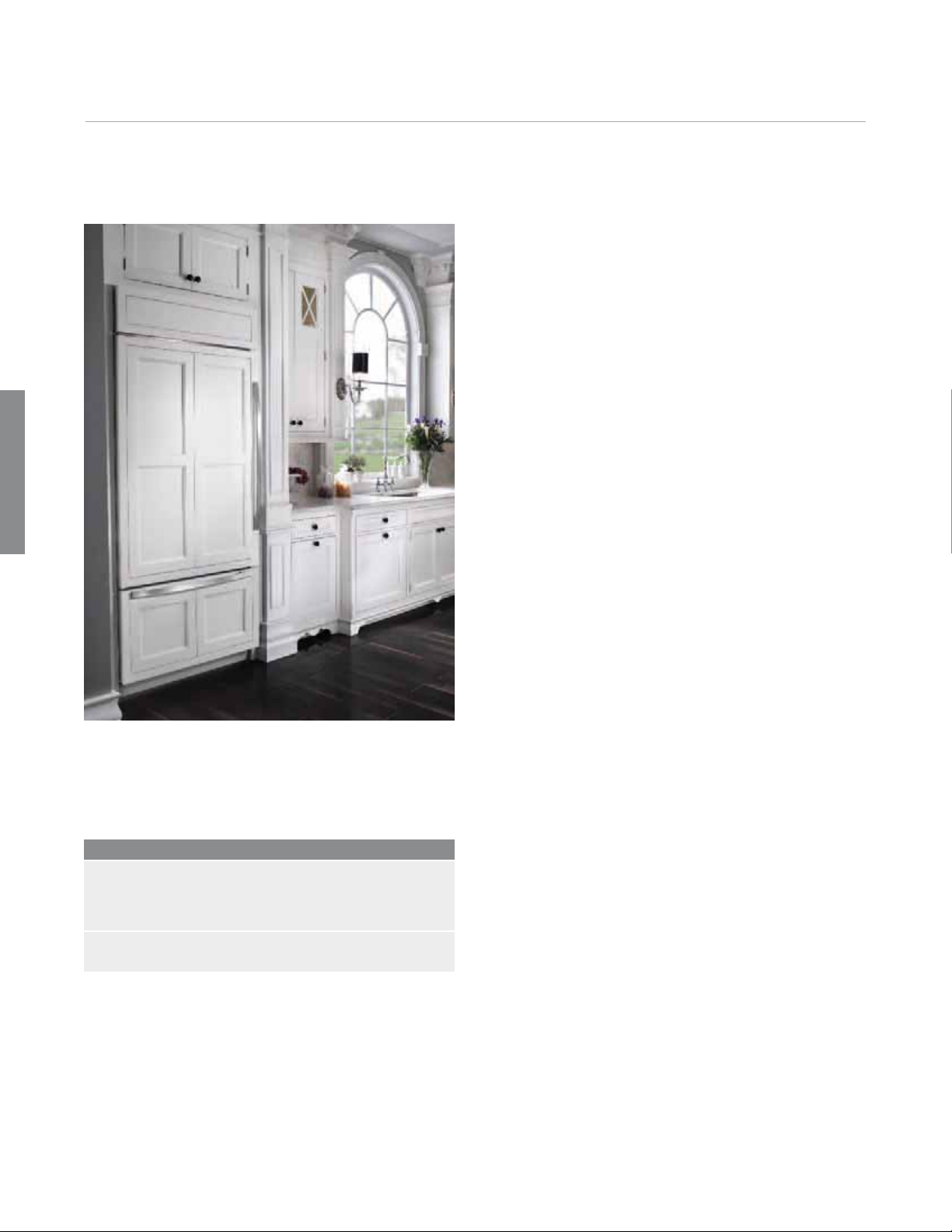
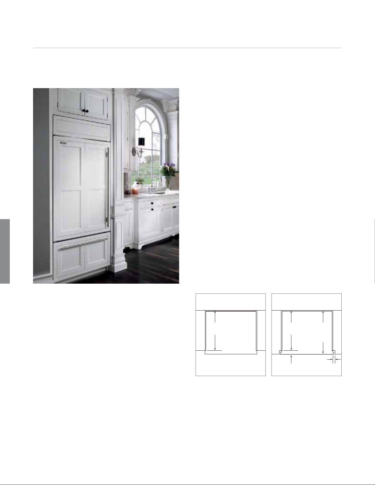
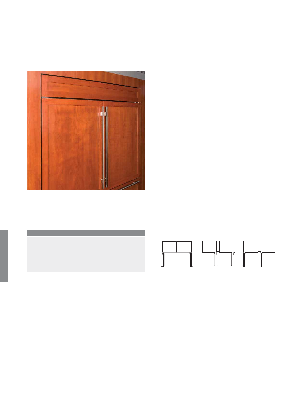
Built-In Design Options. A design classic is now even better. Four distinct design approaches provide limitless
flexibility for creating a beautiful kitchen. New lower profile hinges enable the new built-in units to merge more seamlessly
with surrounding cabinetry. Three handle options coordinate with Wolf cooking products.
Framed. Custom cabinetry
panels slide into the framed
door to blend into the kitchen
design. The framed design
comes with a standard
louvered grille and extruded
handles.
Overlay. Custom cabinet
overlay panels can be
combined with unique hardware for design flexibility.
Shown with curved handle
option to compliment Wolf
E Series ovens.
Page 5

Built-In Design Options 5
subzerotrade.com
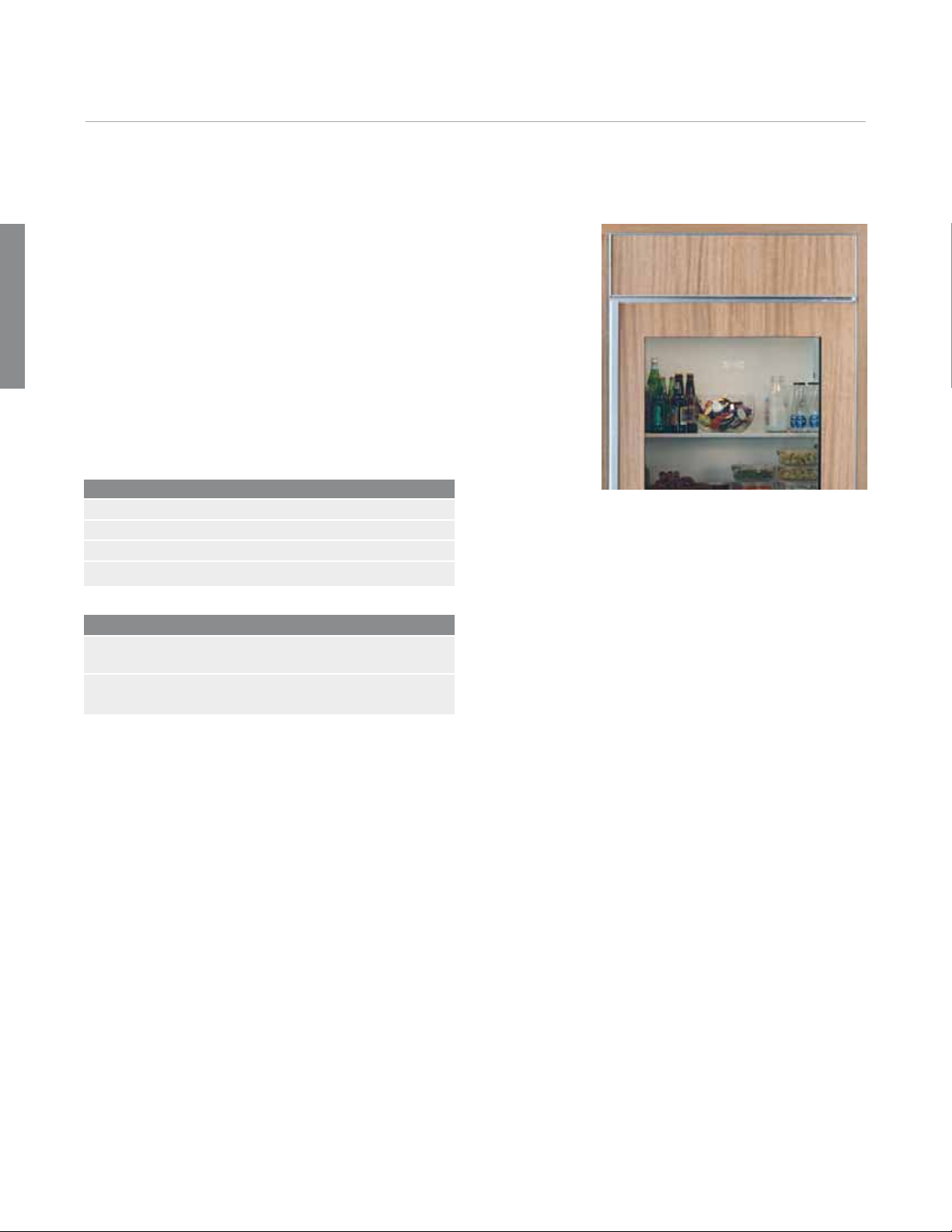
Flush Inset. This brand new
design option allows for a flush
door and grille. Classic,
platinum and carbon stainless
steel panels are available as
sales accessories. Shown with
tubular handle option to mirror
Wolf L Series ovens.
Stainless Steel. For a
professional look, classic
stainless is standard and
requires no customization.
To compliment the look of Wolf
ranges, choose the Pro handle
option shown here.
Page 6

Model Specifications 6
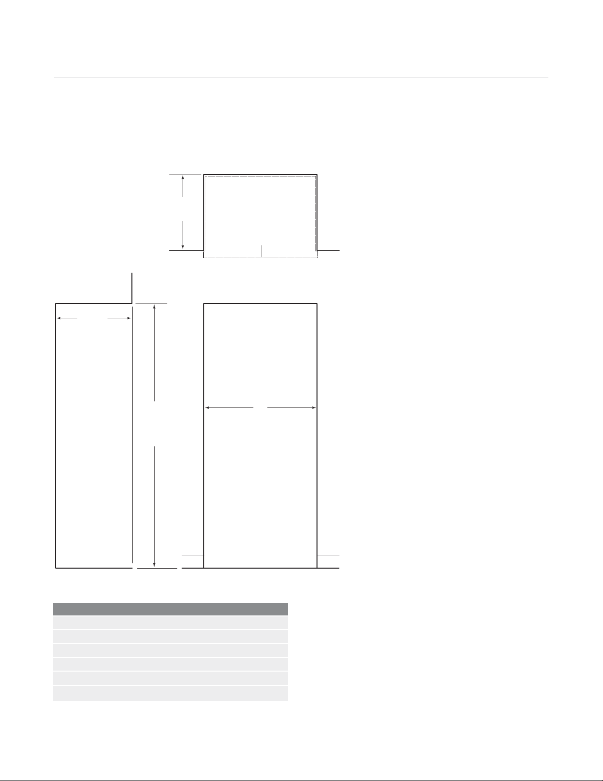
All Refrigerator / All Freezer Models
IMPORTANT NOTE:
The heights of the All
Refrigerator / All Freezer
Models have increased
from 73" (1854) to 84"
(2134).
84"
(2134)
36"
(914)
Model BI-36R
ALL REFRIGERATOR
Model BI-36RG
ALL REFRIGERATOR
GLASS DOOR
Over-and-Under Models
30"
(762)
(914)
30"
(762)
36"
36"
(914)
Model BI-36F
ALL FREEZER
36"
(914)
24"
(610)
SIDE VIEW
36"
(914)
84"
(2134)
24"
(610)
Model BI-30U Model BI-36UG
Model BI-30UG
WITH GLASS DOOR
Model BI-36U
WITH GLASS DOOR
SIDE VIEW
Page 7

Model Specifications 7
subzerotrade.com
Side-by-Side Models
84"
(2134)
36"
(914)
48"
(1219)
42"
(1067)
Model BI-42SModel BI-36S
Model BI-42SD
WITH DISPENSER
42"
(1067)
24"
(610)
SIDE VIEW
Models are shown in the stainless
steel design.
IMPORTANT NOTE: Throughout this
guide, dimensions in parentheses
are millimeters unless otherwise
specified.
84"
(2134)
48"
(1219)
24"
(610)
Model BI-48S
Model BI-48SD
WITH DISPENSER
SIDE VIEW
Page 8

Model Specifications 8
Door Clearance
237/8"
(606)
BEHIND
FRAME
A
C
23/8"
(60)
237/8"
(606)
BEHIND
FRAME
237/8"
(606)
BEHIND
C
BA
23/8"
(60)
FRAME
A
23/8"
(60)
All Refrigerator / All Freezer Models Over-and-Under Models Side-by-Side Models
Door Clearance
ALL REFRIGERATOR / ALL FREEZER A C
BI-36R, BI-36RG and BI-36F 371/4" (946) 17" (432)
OVER-AND-UNDER A B C
BI-30U and BI-30UG 311/4" (796) 235/8" (600) 141/2" (368)
BI-36U and BI-36UG 371/4" (946) 235/8" (600) 17" (432)
SIDE-BY-SIDE A C D
BI-36S 221/4" (565) 101/4" (260) 81/2" (216)
The doors of all built-in models open to a maximum of 110°.
A 90° door stop is shipped with all units. For additional
information, refer to the full-scale templates at the end of this
guide. The handle depth reflects the tubular, curved and pro
handles. For framed handle profile, refer to the full-scale
template on page 38.
IMPORTANT NOTE: For flush inset applications, add
to dimension (A).
BI-42S and BI-42SD 261/4" (668) 121/2" (318) 83/4" (222)
BI-48S and BI-48SD 30" (762) 14" (356) 93/4" (248)
CD
23/8"
(60)
1
/2"(13)
Interior Capacity / Weight
Capacity / Weight R F W
BI-36R 23.3 (660) 420 (191)
BI-36RG 23.5 (665) 430 (195)
BI-36F 22.8 (646) 406 (184)
BI-30U 12.7 (361) 4.1 (116) 462 (210)
BI-30UG 12.9 (367) 4.1 (116) 476 (216)
BI-36U 15.9 (450) 5.2 (148) 515 (234)
BI-36UG 16.1 (447) 5.2 (142) 529 (240)
Capacity / Weight R F W
BI-36S 12.2 (346) 8.0 (227) 538 (244)
BI-42S 16.0 (455) 8.0 (227) 582 (264)
BI-42SD 15.9 (452) 8.1 (230) 608 (276)
BI-48S 18.8 (532) 9.5 (269) 630 (286)
BI-48SD 18.7 (530) 9.6 (272) 656 (298)
Refrigerator (R) and freezer (F) interior capacities are listed in
cubic feet and (liters). Shipping weights (W) are listed in
pounds and (kilograms) and are based on stainless steel
models.
Page 9
Planning Information 9
subzerotrade.com
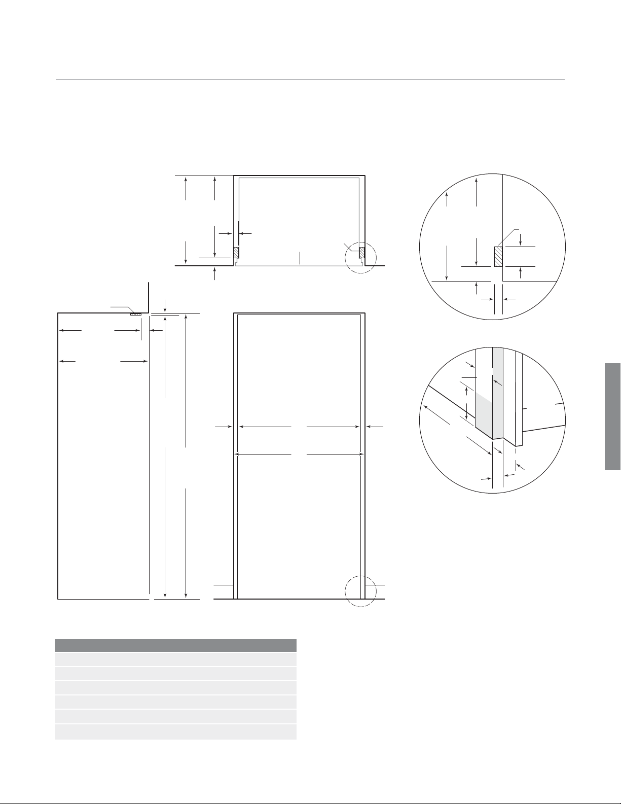
Standard Installation Opening Dimensions
Framed, Overlay and Classic Stainless Steel Models
TOP VIEW
24" (610)
OPENING
24" (610)
OPENING DEPTH
DEPTH
OUTLINE
OF UNIT WITH
3
/4" (19) PANEL
SIDE VIEW
833/4"
(2127)
OPENING
HEIGHT
83" min
(2108)
A
OPENING WIDTH
FRONT VIEW
Opening Width A
BI-36R, BI-36RG and BI-36F 351/2" (902)
BI-30U and BI-30UG 291/2" (746)
BI-36U and BI-36UG 351/2" (902)
BI-36S 351/2" (902)
BI-42S and BI-42SD 411/2" (1054)
BI-48S and BI-48SD 471/2" (1206)
IMPORTANT NOTE: If two units are installed side by side,
refer to pages 30–31 for dual standard installations.
Classic stainless steel models are ready to install out of the
box.
Page 10

Planning Information 10
Electrical Requirements. For all built-in models, the
electrical supply should be located within the shaded area
shown in the illustration. Follow the National Electrical
Code and local codes and ordinances when installing
the receptacle. A separate circuit, servicing only this
appliance is required.
IMPORTANT NOTE: A ground fault circuit interrupter
(GFCI) is not recommended and may cause interruption of
operation.
Electrical Requirements
Power Supply 115 V AC, 60 Hz
Circuit Breaker 15 amp
Receptacle 3-prong grounding-type
FRONT VIEW
Location of electrical supply.
7"
(178)
E
6"
(152)
751/2"
(1918)
Page 11
Planning Information 11
subzerotrade.com
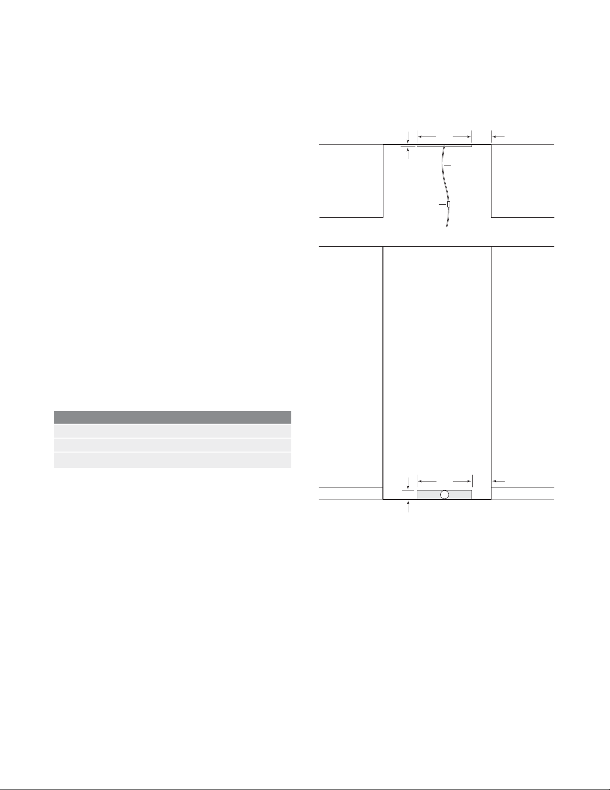
Plumbing Requirements. All built-in models with an
automatic ice maker come with a microbiological water
filtration system. The water supply line should be located
within the shaded area shown in the illustration. The
water supply line should be connected to the house
supply with an easily accessible shut-off valve between
the supply and the unit. Do not use self-piercing valves.
A saddle valve kit (4200880) is available from your
Sub-Zero dealer. The water line must not interfere with
installation of the anti-tip brackets.
IMPORTANT NOTE: A reverse osmosis system can be
used provided there is constant water pressure of 30 psi
(2.1 bar) to 100 psi (6.9 bar) supplied to the unit at all
times. In this application, the microbiological water filtration system should be set to bypass mode by removing
the water filter cartridge and inserting the bypass plug
(7005018) available from your Sub-Zero dealer. Installation
instructions packed with the unit will outline this
procedure.
Plumbing Requirements
Water Supply Line
Water Pressure 30–100 psi (2.1–6.9 bar)
Excess Water Line for Connection 36" (914)
1
/4" OD copper line
1
/2"
(13)
3" (76)
SHUT-OFF
VALV E
TOP VIEW
FRONT VIEW
18"
(457)
18"
(457)
W
(152)
WATER LINE
(152)
6"
6"
Location of water supply.
Page 12

Framed
Framed Panels 12
Framed Panels. If you and your client have ordered a
framed model, you will be adding panels to give the unit
the traditional Sub-Zero look. The framed panel design
option is available for all built-in framed models. For exact
door panel dimensions for built-in framed models, refer to
framed panel specifications on the following pages. Also
refer to the full-scale templates at the end of this guide
for additional panel and handle considerations.
The traditional framed models come with an elegant,
smooth, full-length handle. Optional extended full-length
handles that provide additional finger clearance for raised
panels are available through your Sub-Zero dealer.
Custom cabinetry panels slide into the framed door to
blend into the kitchen design. The framed design comes
with a standard louvered grille and extruded handles.
Framed Panel Requirements
MAX WEIGHT PER PANEL
BI-36R, BI-36RG and BI-36F 75 lbs (34 kg)
All Other Framed Models 50 lbs (23 kg)
MIN PANEL THICKNESS
All Framed Panels
1
/4" (6)
Page 13

Framed Panels 13
subzerotrade.com
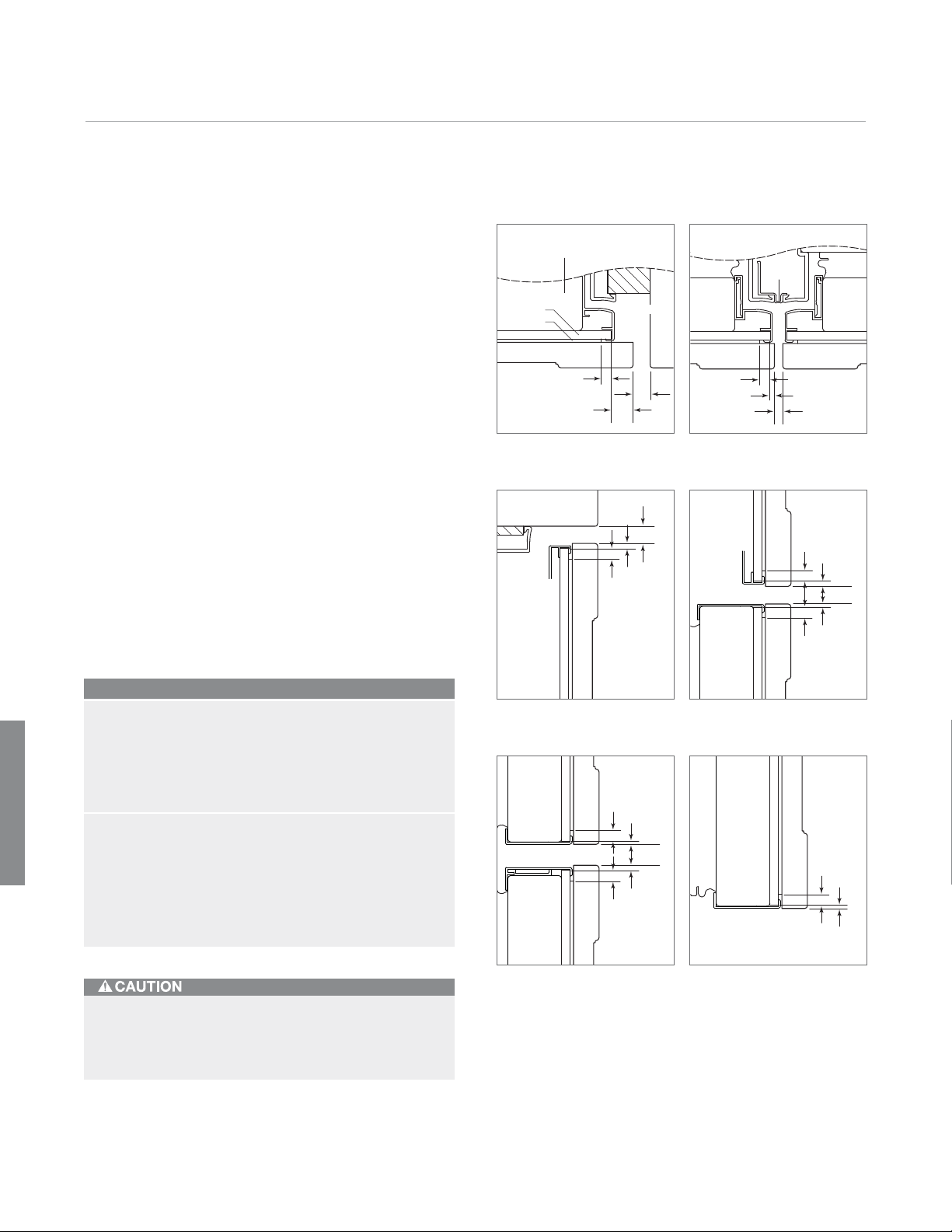
Framed Panels. If the thickness of the custom panels
is less than
of shim material to build the total thickness to
the panel is thicker than
1
/4" (6), they must be backed up with a sheet
1
/4" (6). If
1
/4" (6), a routed edge must be
provided around the panel to ensure a proper fit. Refer to
the illustrations.
IMPORTANT NOTE: On all framed models, routing,
recessing or optional extended handles may be required
on raised panels for finger clearance under the handle.
Refer to the full-scale templates at the end of this guide.
TRIM
REVEAL
1
/4" (6) min
1
/4" (6)
PANEL
MAIN FRAME
DOOR
TRIM
REVEAL
1
/4" (6) min
ROUT TO
1
/4" (6)
MAIN FRAME
DOOR
Framed
IMPORTANT NOTE: On glass door models, the edges of
the window cut-out will need to be finished, as they will
be exposed.
IMPORTANT NOTE: When installing two units in a side by
side application, refer to pages 30–31 for dual standard
installations. Be aware that rough opening dimensions are
different for this application.
Do not exceed the framed decorative panel dimensions. Exceeding dimensions could cause damage
to the panels and the Sub-Zero unit.
Panels1/4" (6) thick or less. Panels thicker than1/4" (6).
Page 14

Framed Panels 14
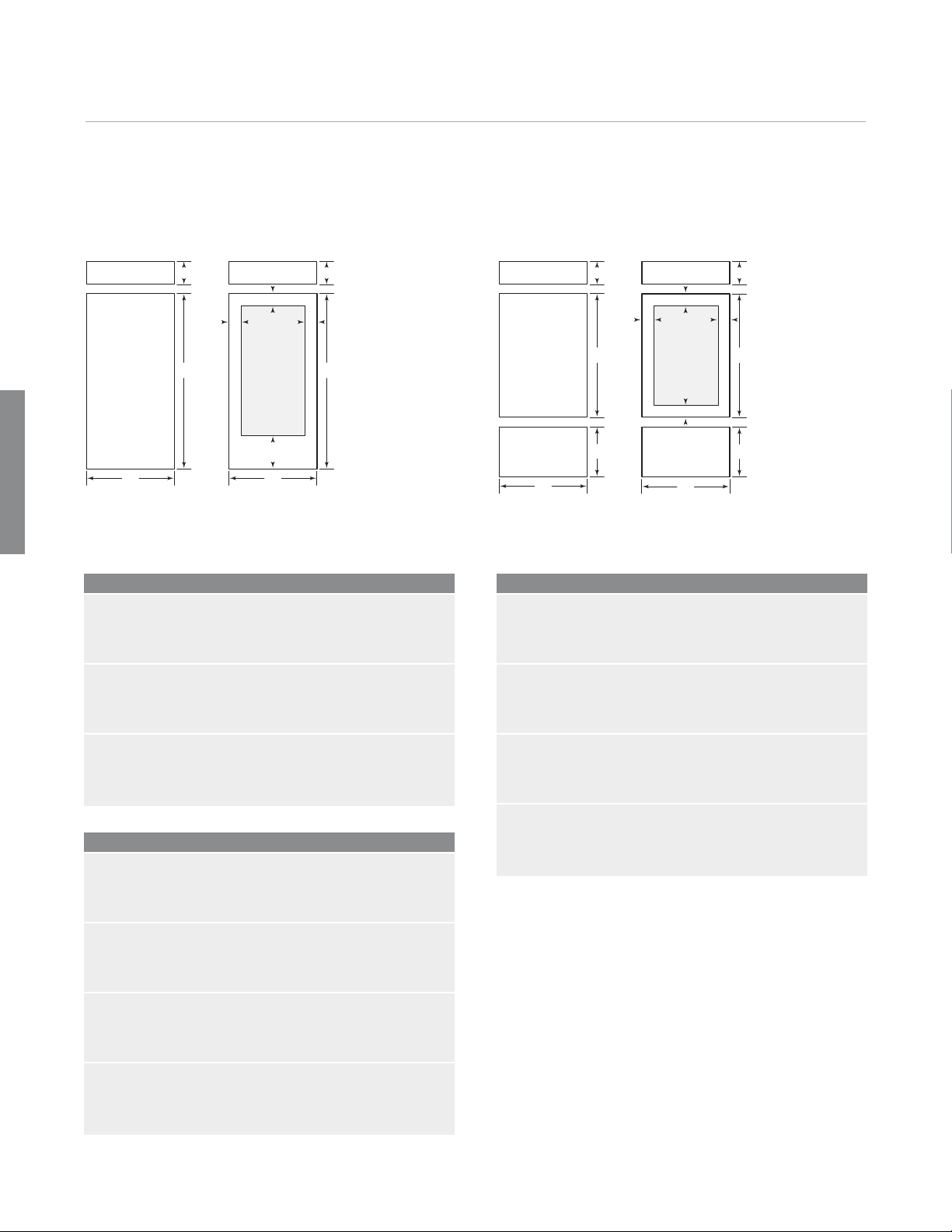
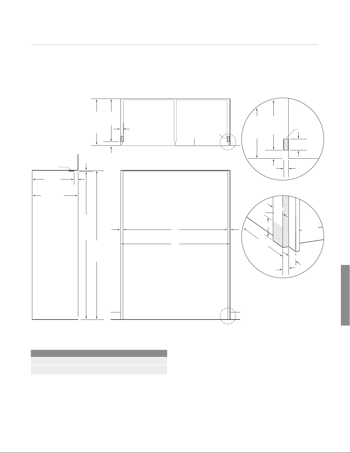
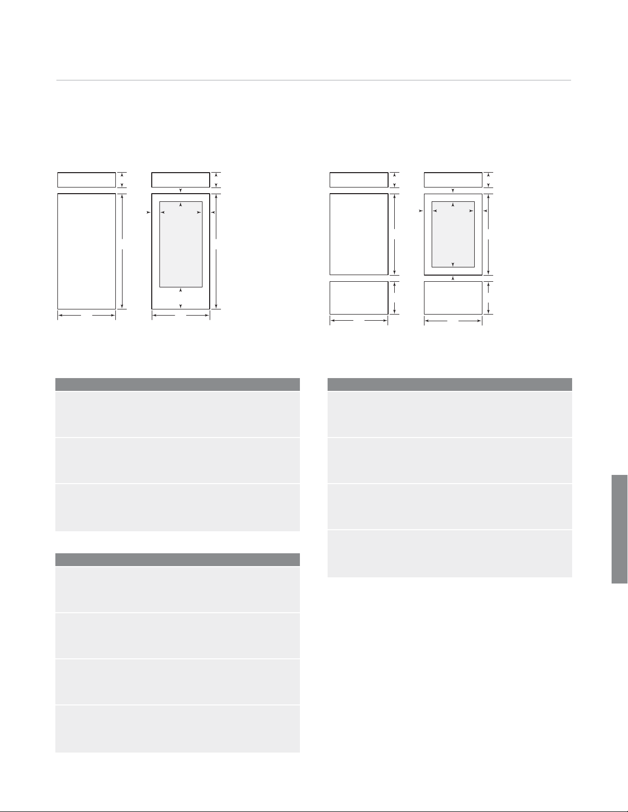
Framed Panel Specifications
Framed
A
A A
H
B
W
W
H
BI-36R / BI-36F BI-36RG
Models BI-36R, BI-36RG and BI-36F
REFRIGERATOR/FREEZER W H
Door Panel 353/4" (908) 699/16" (1767)
BI-36RG W H
Window Cut-Out 251/2" (648) 541/16" (1373)
AB
Cut-Out Location 53/16" (132) 105/16" (262)
A
A A
H
A
H
W
W
H
H
BI-30U / BI-36U BI-30UG / BI-36UG
Models BI-30U and BI-30UG
REFRIGERATOR W H
Door Panel 293/4" (756) 4915/16" (1268)
FREEZER W H
Drawer Panel 293/4" (756) 1811/16" (475)
BI-30UG W H
Window Cut-Out 191/2" (495) 3911/16" (1008)
Cut-Out Location 53/16" (132)
A
Models BI-36U and BI-36UG
REFRIGERATOR W H
Door Panel 353/4" (908) 4915/16" (1268)
FREEZER W H
Drawer Panel 353/4" (908) 1811/16" (475)
BI-36UG W H
Window Cut-Out 251/2" (648) 3911/16" (1008)
Cut-Out Location 53/16" (132)
A
Page 15

Framed Panels 15
subzerotrade.com
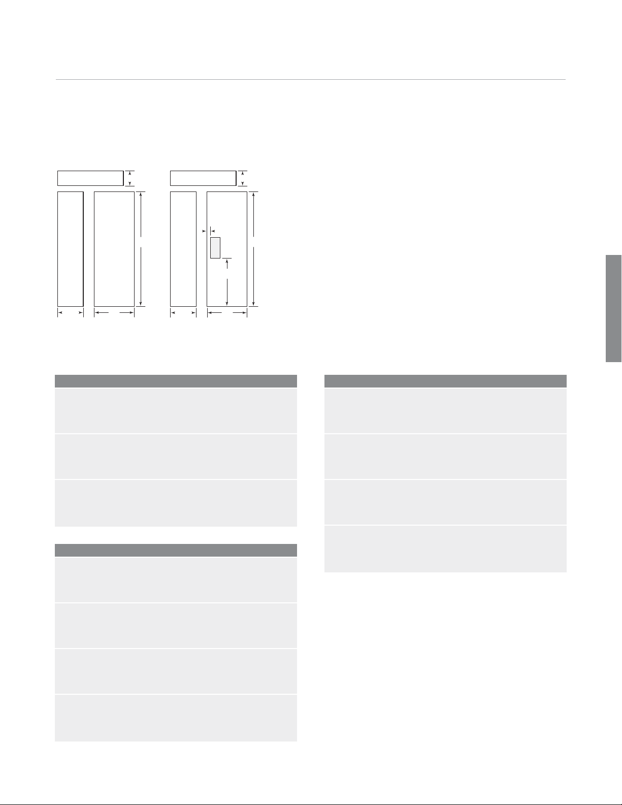
Framed Panel Specifications
A
H
H
B
Framed
WW
WW
BI-36S / BI-42S / BI-48S BI-42SD / BI-48SD
Model BI-36S
REFRIGERATOR W H
Door Panel 1913/16" (503) 699/16" (1767)
FREEZER W H
Door Panel 157/16" (392) 699/16" (1767)
Models BI-42S and BI-42SD
REFRIGERATOR W H
Door Panel 2413/16" (630) 699/16" (1767)
FREEZER W H
Door Panel 167/16" (418) 699/16" (1767)
BI-42SD W H
Dispenser Cut-Out 57/8" (149) 127/16" (316)
AB
Cut-Out Location 17/8" (48) 283/4" (730)
Models BI-48S and BI-48SD
REFRIGERATOR W H
Door Panel 281/2" (724) 699/16" (1767)
FREEZER W H
Door Panel 183/4" (418) 699/16" (1767)
BI-48SD W H
Dispenser Cut-Out 57/8" (149) 127/16" (316)
AB
Cut-Out Location 17/8" (48) 283/4" (730)
For Models BI-42SD and BI-48SD, panel thickness in the
1
dispenser area can range from
1
/8" (29). If the panel is thicker, you must rout out a mini-
1
1
/4" (6) flat landing area to accommodate the glasswell
mum
/4" (6) to a maximum of
bezel.
Page 16
Framed
Framed Panels 16
Optional Panel Grille. A louvered grille, providing an
4" (2134) overall unit height, is standard on framed
8
applications. You may choose to use Sub-Zero’s optional
panel grille for your application. The panel grilles can be
used with all built-in models and are available for 83"
(2108), 84" (2134) and 88" (2235) overall unit heights.
Grille panel dimensions listed are for a standard 84"
(2134) overall height of the unit. For an 83" (2108) overall
height, subtract 1" (25) from grille panel height dimensions. For an 88" (2235) overall height, add 4" (102) to
height dimensions.
Optional Grille Panel W H
30" (762) Models 293/4" (756) 815/16" (227)
36" (914) Models 353/4" (908) 815/16" (227)
42" (1067) Models 413/4" (1060) 815/16" (227)
48" (1219) Models 473/4" (1213) 815/16" (227)
Optional panel grille.
Grille Panel Requirements
MAX WEIGHT
Grille Panel 13 lbs (6 kg)
MIN PANEL THICKNESS
Grille Panel
1
/4" (6)
Page 17
Framed Panels 17
subzerotrade.com
Partial Framed Option. If you choose not to use
custom panels above and below the glasswell for
dispenser Model BI-42SD or BI-48SD, a stainless steel
insert panel is available as a sales accessory. This
accessory kit includes partial framed molding and classic
stainless steel panel to provide a spill-resistant finish
above and below the glasswell on the refrigerator door
only. The partial framed accessory kit (7004855) is
available through your Sub-Zero dealer. Refer to panel
dimensions for the partial framed option below.
H
WW
Framed
IMPORTANT NOTE: When using raised panels with the
partial framed kit, a
1
/2" (13) trim reveal down to1/4"(6)
thickness is necessary at the bezel for the panels to fit
properly.
Optional Partial Framed Panels
MODEL BI-42SD W H
Refrigerator Panel 151/16" (383) 699/16" (1767)
Freezer Panel 151/16" (383) 699/16" (1767)
MODEL BI-48SD W H
Refrigerator Panel 163/4" (425) 699/16" (1767)
Freezer Panel 163/4" (425) 699/16" (1767)
Partial Framed Kit
BI-42SD / BI-48SD
Partial Framed Option
Page 18
Overlay Panels 18
Overlay Panels. If you and your client have ordered
an overlay model, you will be adding panels and handles
to give the unit a more custom look. The overlay panel
design option is available for all built-in overlay models.
For exact door panel dimensions, refer to overlay panel
specifications on the following pages.
IMPORTANT NOTE: Overlay models can be used in a
overlay or a flush inset application. Be aware that the
application specified will affect panel sizes, rough opening dimensions and installation.
Overlay
Custom cabinet overlay panels can be combined with
unique hardware for design flexibility. Shown with curved
handle option to compliment Wolf E Series ovens.
Overlay Panel Requirements
MAX WEIGHT PER PANEL
BI-36R, BI-36RG and BI-36F 75 lbs (34 kg)
All Other Overlay Models 50 lbs (23 kg)
Grille Panel 13 lbs (6 kg)
MIN PANEL THICKNESS
All Overlay Panels
5
/8" (16)
The overlay design allows decorative panels to cover the
door trim for a more seamless appearance that blends
with the design of the room. The most common way to
achieve this look is to work with three panels—the decorative overlay panel which is typically
spacer panel and a
1
/4" (6) backer panel. Depending on
3
/4" (19), a .10" (3)
your cabinet manufacturer, this could also be one panel
routed for different dimensions.
Regardless of the physical construction of the panels
(three-panel assembly or routed panel), you will need to
follow the overlay panel specifications on the following
pages for exact sizing and panel placement to ensure a
proper fit.
Page 19
Overlay Panels 19
subzerotrade.com
Overlay Panels. The illustrations provide a cross
section view of the three-panel assembly showing placement of the trim and a rear view of the three-panel
assembly with critical dimensions, standard for all built-in
models.
Overlay grille panels for the panel grille match the design
of the overlay door panels. Dimensions for the grille panel
are listed in the overlay panel specifications on the following pages.
IMPORTANT NOTE: On glass door models, the edges of
the window cut-out will need to be finished, as they will
be exposed.
IMPORTANT NOTE: When installing two units in a side by
side application, refer to pages 30–31 for dual standard
installations. Be aware that rough opening dimensions are
different for this application.
Do not exceed the overlay decorative panel dimensions. Exceeding dimensions could cause damage
to the panels and the Sub-Zero unit.
SPACER PANEL
OVERLAY PANEL
BACKER PANEL
TRIM
5
/16" (8) min
1
/8"
(3)
Panel assembly cross
section.
OVERLAY
PANEL
3
/4"
(19)
typical
.10" (3)
1
/4" (6)
SPACER
PANEL
BACKER
PANEL
Panel assembly rear view.
Overlay
Page 20
Overlay Panels 20
Overlay Panel Specifications
Overlay
HH
A
A A
H
B
W
W
H
W
H H
A
A A
H
A
H
W
H
H
BI-36R / BI-36F BI-36RG BI-30U / BI-36U BI-30UG / BI-36UG
Models BI-36R, BI-36RG and BI-36F
REFRIGERATOR/FREEZER W H
Overlay Panel 36" (914) 693/4" (1772)
Spacer Panel 351/8" (892) 6815/16" (1751)
Backer Panel 353/4" (908) 699/16" (1767)
GRILLE W H
Overlay Panel 36" (914) 91/4" (235)
Spacer Panel 351/8" (892) 85/16" (211)
Backer Panel 353/4" (908) 815/16" (227)
BI-36RG W H
Window Cut-Out 251/2" (648) 541/8" (1375)
AB
Cut-Out Location 51/4" (133) 103/8" (264)
Models BI-30U and BI-30UG
REFRIGERATOR W H
Models BI-36U and BI-36UG
REFRIGERATOR W H
Overlay Panel 36" (914) 501/8" (1273)
Spacer Panel 351/8" (892) 495/16" (1253)
Backer Panel 353/4" (908) 4915/16" (1268)
FREEZER W H
Overlay Panel 36" (914) 19" (483)
Spacer Panel 351/8" (892) 181/16" (459)
Backer Panel 353/4" (908) 1811/16" (475)
GRILLE W H
Overlay Panel 36" (914) 91/4" (235)
Spacer Panel 351/8" (892) 85/16" (211)
Backer Panel 353/4" (908) 815/16" (227)
BI-36UG W H
Window Cut-Out 251/2" (648) 395/8" (1006)
Cut-Out Location 51/4" (133)
Overlay Panel 30" (762) 501/8" (1273)
Spacer Panel 291/8" (740) 495/16" (1253)
Backer Panel 293/4" (756) 4915/16" (1268)
FREEZER W H
Overlay Panel 30" (762) 19" (483)
Spacer Panel 291/8" (740) 181/16" (459)
Backer Panel 293/4" (756) 1811/16" (475)
GRILLE WH
Grille panel dimensions listed are for a standard 84" (2134)
overall height of the unit. For an 83" (2108) overall height,
subtract 1" (25) from grille panel height dimensions. For an
88" (2235) overall height, add 4" (102) to height dimensions.
Width dimensions do not vary.
Overlay Panel 30" (762) 91/4" (235)
Spacer Panel 291/8" (740) 85/16" (211)
Backer Panel 293/4" (756) 815/16" (227)
BI-30UG W H
Window Cut-Out 191/2" (495) 395/8" (1006)
A
Cut-Out Location 51/4" (133)
A
Page 21
Overlay Panels 21
subzerotrade.com
Overlay Panel Specifications
H H
A
H
WW
BI-36S / BI-42S / BI-48S BI-42SD / BI-48SD
H
B
WW
Overlay
Model BI-36S
REFRIGERATOR W H
Overlay Panel 201/16" (510) 693/4" (1772)
Spacer Panel 193/16" (487) 6815/16" (1751)
Backer Panel 1913/16" (503) 699/16" (1767)
FREEZER W H
Overlay Panel 1511/16" (398) 693/4" (1772)
Spacer Panel 1413/16" (376) 6815/16" (1751)
Backer Panel 157/16" (392) 699/16" (1767)
GRILLE W H
Overlay Panel 36" (914) 91/4" (235)
Spacer Panel 351/8" (892) 85/16" (211)
Backer Panel 353/4" (908) 815/16" (227)
Models BI-42S and BI-42SD
REFRIGERATOR W H
Overlay Panel 251/16" (637) 693/4" (1772)
Spacer Panel 243/16" (614) 6815/16" (1751)
Backer Panel 2413/16" (630) 699/16" (1767)
FREEZER W H
Overlay Panel 1611/16" (424) 693/4" (1772)
Spacer Panel 1513/16" (402) 6815/16" (1751)
Backer Panel 167/16" (418) 699/16" (1767)
GRILLE W H
Overlay Panel 42" (1067) 91/4" (235)
Spacer Panel 411/8" (1045) 85/16" (211)
Backer Panel 413/4" (1060) 815/16" (227)
BI-42SD W H
Dispenser Cut-Out 57/8" (149) 127/16" (316)
AB
Cut-Out Location 2" (51) 2813/16" (732)
Models BI-48S and BI-48SD
REFRIGERATOR W H
Overlay Panel 283/4" (730) 693/4" (1772)
Spacer Panel 277/8" (708) 6815/16" (1751)
Backer Panel 281/2" (724) 699/16" (1767)
FREEZER W H
Overlay Panel 19" (483) 693/4" (1772)
Spacer Panel 181/8" (460) 6815/16" (1751)
Backer Panel 183/4" (476) 699/16" (1767)
GRILLE W H
Overlay Panel 48" (1219) 91/4" (235)
Spacer Panel 471/8" (1197) 85/16" (211)
Backer Panel 473/4" (1213) 815/16" (227)
BI-48SD W H
Dispenser Cut-Out 57/8" (149) 127/16" (316)
AB
Cut-Out Location 2" (51) 2813/16" (732)
Grille panel dimensions listed are for a standard 84" (2134)
overall height of the unit. For an 83" (2108) overall height,
subtract 1" (25) from grille panel height dimensions. For an
88" (2235) overall height, add 4" (102) to height dimensions.
Width dimensions do not vary.
Page 22
Flush Inset
Flush Inset Application 22
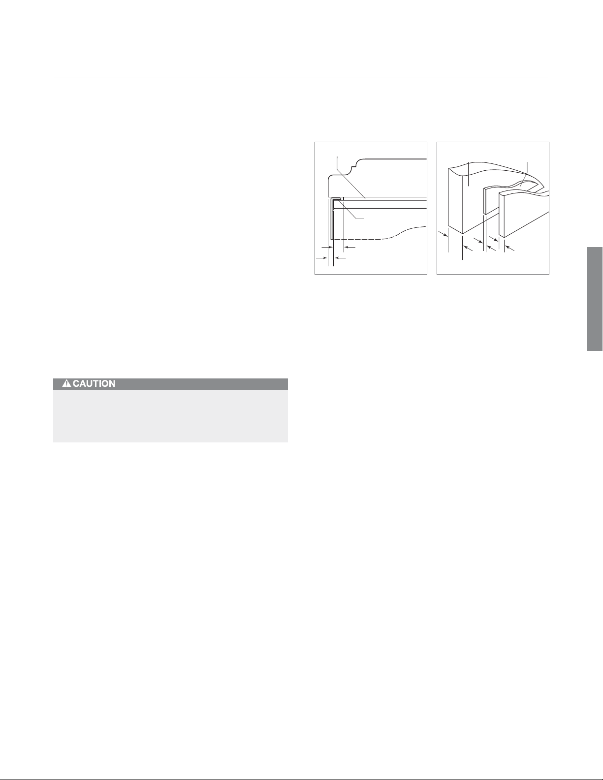
Flush Inset Application. It is necessary to consider
the following points when planning for a flush inset
application:
• The flush inset depth is 2
standard opening.
• The flush inset width is 2
standard opening.
• The flush inset height is1/4" (6) higher than the
standard opening.
• Panel widths increase to achieve the flush inset look.
• You must allow a
1
of the unit and grille to allow for proper door swing
and airflow.
IMPORTANT NOTE: Do not confuse the flush inset application as being a separate model. This is an overlay unit in a
flush installation. The same model is used in an overlay or
flush inset application.
Rough opening dimensions for the new flush inset application assume the use of a
illustrations below show the difference between standard
and flush inset installations.
3
/16" (56) deeper than the
1
/2" (64) wider than the
/2" (13) reveal around the perimeter
3
/4" (19) decorative panel. The
This brand new design option allows for a flush door and
grille. Classic, platinum and carbon stainless steel panels
are available as sales accessories. Shown with tubular
handle option to mirror Wolf L Series ovens.
FLUSH INSET INSTALLATION
3
/4" (19) PANEL
STANDARD INSTALLATION
24" (610)
OPENING
DEPTH
TOP VIEW
WITH
24" (610)
OPENING
DEPTH
23/16"
(56)
TOP VIEW
263/16"
(665)
FLUSH
INSET
DEPTH
Standard installation. Flush inset installation.
11/4"
(32)
Page 23
Flush Inset Application 23
11/4"
(32)
24"
(610)
OPENING
DEPTH
TO CLEAT
CLEAT
TOP VIEW
263/16"
(665)
FLUSH
INSET
DEPTH
23/16"
(56)
3"
(76)
typical
24"
(610)
OPENING
DEPTH TO
CLEAT
11/4"
(32)
23/16"
(56)
CLEAT
SHADED
AREA
MUST BE
FINISHED
3"
typical
(76)
4"
(102)
subzerotrade.com
Flush Inset Installation Opening Dimensions
TOP VIEW
24" (610)
CLEAT
1
(6)
263/16"
/4"
(665)
FLUSH
INSET
DEPTH
DEPTH
TO CLEAT
23/16"
(56)
11/4"
(32)
OUTLINE
OF UNIT WITH
3
/4" (19) PANEL
CLEAT
DETAIL A
24" (610)
DEPTH TO CLEAT
263/16" (665)
FLUSH INSET DEPTH
SIDE VIEW
23/16"
(56)
833/4"
(2127)
HEIGHT
TO CLEAT
83" min
(2108)
84"
(2134)
FLUSH
INSET
HEIGHT
11/4"
(32)
A
WIDTH TO CLEAT
B
FLUSH INSET WIDTH
DETAIL B
FRONT VIEW
11/4"
(32)
Detail A
Flush Inset
Detail B
Flush Inset Opening Widths A B
BI-36R, BI-36RG and BI-36F 351/2" (902) 38" (965)
BI-30U and BI-30UG 291/2" (746) 32" (813)
BI-36U and BI-36UG 351/2" (902) 38" (965)
BI-36S 351/2" (902) 38" (965)
BI-42S and BI-42SD 411/2" (1054) 44" (1118)
BI-48S and BI-48SD 471/2" (1206) 50" (1270)
IMPORTANT NOTE: Dimensions assume a3/4" (19) panel
thickness.
IMPORTANT NOTE: If two units are installed side by side,
refer to pages 32–33 for dual flush inset installations.
Page 24
Flush Inset
Flush Inset Panels 24
Flush Inset Panels. The flush inset application allows
decorative panels on the front of the unit to be flush with
surrounding cabinetry and is available for all built-in
overlay models. For exact panel dimensions, refer to flush
inset panel specifications on the following pages.
The flush inset design allows decorative panels to cover
the door trim for a seamless appearance that blends with
the design of the room. The most common way to
achieve this look is to work with three panels—the decorative flush inset panel which is typically
(3) spacer panel and a
1
/4" (6) backer panel. Depending
3
/4" (19), a .10"
on your cabinet manufacturer, this could also be one
panel routed for different dimensions.
Regardless of the physical construction of the panels
(three-panel assembly or routed panel), you will need to
follow the flush inset panel specifications on the following
pages for exact sizing and panel placement to ensure a
proper fit.
The illustration to the right provides a rear view of the
three-panel assembly with critical dimensions, standard
for all built-in models.
Do not exceed the flush inset decorative panel
dimensions. Exceeding dimensions could cause
damage to the panels and the Sub-Zero unit.
Flush Inset Panel Requirements
MAX WEIGHT PER PANEL
BI-36R, BI-36RG and BI-36F 75 lbs (34 kg)
All Other Flush Inset Models 50 lbs (23 kg)
Grille Panel 13 lbs (6 kg)
MIN PANEL THICKNESS
All Flush Inset Panels
FLUSH INSET
PANEL
5
/8" (16)
SPACER
PANEL
BACKER
PANEL
IMPORTANT NOTE: The inside edges of the rough open-
ing as well as the sides and a portion of the back side of
the decorative panels will need to be finished, as they will
be exposed when the doors are open.
IMPORTANT NOTE: On glass door models, the edges of
the window cut-out will need to be finished, as they will
be exposed.
IMPORTANT NOTE: For flush inset panels thicker than
3
/4"
(19), a 90˚ door stop may be needed to avoid interference
with adjacent cabinets. Refer to the full-scale templates
at the end of this guide.
IMPORTANT NOTE: When installing two units side by side
in a flush inset application, refer to pages 32–35 for dual
flush inset installations. Be aware that rough opening
dimensions, panel sizes and offsets are different for this
application.
3
/4"
(19)
typical
.10" (3)
1
/4" (6)
Three-panel assembly
Page 25
Flush Inset Panels 25
subzerotrade.com
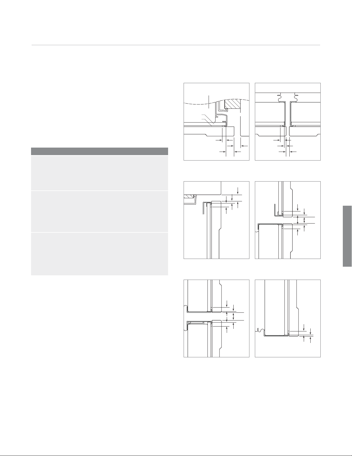
Flush Inset Panels. Illustrations A–F provide panel
offsets and reveals for all built-in models in a flush inset
application. Refer to the chart below for reference to the
illustrations relating to your specific model.
For additional information on model specific panel
reveals, visit the Specification Library section of our
website, subzerotrade.com.
Panel Offsets Illus.
ALL REFRIGERATOR / ALL FREEZER
Door / Grille Sides A
Grille Top C
Grille Bottom / Door Top D
Door Bottom F
OVER-AND-UNDER
Door / Drawer / Grille Sides A
Grille Top C
Grille Bottom / Door Top D
Door Bottom / Drawer Top E
Drawer Bottom F
SIDE-BY-SIDE
Doors (hinge) / Grille Sides A
Doors (handle) Sides B
Grille Top C
Grille Bottom / Door Top D
Door Bottom F
5
/16" (8)
TOP VIEW
CABINETRY
1
/2"
(13)
5
/8"
(16)
DOOR DOOR
5
/16" (8)
1
DOOR / DRAWER / GRILLE
BACKER
SPACER
FLUSH INSET PANEL
Illus. A Illus. B
CABINETRY
1
GRILLE
1
5
/16"
(8)
SIDE VIEW
/8"
(3)
/2"(13)
GRILLE
DOOR
Illus. C Illus. D
/8" (3)
TOP VIEW
1
/4" (6)
REVEAL
5
/16"
5
(8)
3
5
/16"
(8)
SIDE VIEW
/32"
(4)
/32"
(2)
1
/2"(13)
Flush Inset
5
/16"
3
(8)
/32"
5
/16"
(8)
SIDE VIEW
(2)
5
/8"(16)
5
/32"
(4)
DOOR
DRAWER
Illus. E Illus. F
DOOR /
DRAWER
SIDE VIEW
5
/16"
(8)
3
/32"
(2)
Page 26

Flush Inset Panels 26
Flush Inset Panel Specifications
Flush Inset
HH
A
A A
H
B
W
W
H
W
H H
B
A A
H
B
H
W
H
H
BI-36R / BI-36F BI-36RG BI-30U / BI-36U BI-30UG / BI-36UG
Models BI-36R, BI-36RG and BI-36F
REFRIGERATOR/FREEZER W H
Flush Inset Panel 37" (940) 693/4" (1772)
Spacer Panel 351/8" (892) 6815/16" (1751)
Backer Panel 353/4" (908) 699/16" (1767)
GRILLE W H
Flush Inset Panel 37" (940) 91/4" (235)
Spacer Panel 351/8" (892) 85/16" (211)
Backer Panel 353/4" (908) 815/16" (227)
BI-36RG W H
Window Cut-Out 251/2" (648) 541/8" (1375)
AB
Cut-Out Location 53/4" (146) 103/8" (264)
Models BI-36U and BI-36UG
REFRIGERATOR W H
Flush Inset Panel 37" (940) 501/8" (1273)
Spacer Panel 351/8" (892) 495/16" (1253)
Backer Panel 353/4" (908) 4915/16" (1268)
FREEZER W H
Flush Inset Panel 37" (940) 19" (483)
Spacer Panel 351/8" (892) 181/16" (459)
Backer Panel 353/4" (908) 1811/16" (475)
GRILLE W H
Flush Inset Panel 37" (940) 91/4" (235)
Spacer Panel 351/8" (892) 85/16" (211)
Backer Panel 353/4" (908) 815/16" (227)
BI-36UG W H
Window Cut-Out 251/2" (648) 395/8" (1006)
Models BI-30U and BI-30UG
REFRIGERATOR W H
Cut-Out Location 53/4" (146) 51/4" (133)
Flush Inset Panel 31" (787) 501/8" (1273)
Spacer Panel 291/8" (740) 495/16" (1253)
Backer Panel 293/4" (756) 4915/16" (1268)
FREEZER W H
Flush Inset Panel 31" (787) 19" (483)
Spacer Panel 291/8" (740) 181/16" (459)
Backer Panel 293/4" (756) 1811/16" (475)
GRILLE WH
Grille panel dimensions listed are for a standard 84" (2134)
overall height of the unit. For an 83" (2108) overall height,
subtract 1" (25) from grille panel height dimensions. For an
88" (2235) overall height, add 4" (102) to height dimensions.
Width dimensions do not vary.
Flush Inset Panel 31" (787) 91/4" (235)
Spacer Panel 291/8" (740) 85/16" (211)
Backer Panel 293/4" (756) 815/16" (227)
BI-30UG W H
Window Cut-Out 191/2" (495) 395/8" (1006)
AB
Cut-Out Location 53/4" (146) 51/4" (133)
AB
Page 27

Flush Inset Panels 27
subzerotrade.com
Flush Inset Panel Specifications
H H
A
H
H
B
WW
WW
BI-36S / BI-42S / BI-48S BI-42SD / BI-48SD
Model BI-36S
REFRIGERATOR W H
Flush Inset Panel 209/16" (522) 693/4" (1772)
Spacer Panel 193/16" (487) 6815/16" (1751)
Backer Panel 1913/16" (503) 699/16" (1767)
FREEZER W H
Flush Inset Panel 163/16" (411) 693/4" (1772)
Spacer Panel 1413/16" (376) 6815/16" (1751)
Backer Panel 157/16" (392) 699/16" (1767)
GRILLE W H
Flush Inset Panel 37" (940) 91/4" (235)
Spacer Panel 351/8" (892) 85/16" (211)
Backer Panel 353/4" (908) 815/16" (227)
Models BI-42S and BI-42SD
REFRIGERATOR W H
Flush Inset Panel 259/16" (649) 693/4" (1772)
Spacer Panel 243/16" (614) 6815/16" (1751)
Backer Panel 2413/16" (630) 699/16" (1767)
FREEZER W H
Flush Inset Panel 173/16" (437) 693/4" (1772)
Spacer Panel 1513/16" (402) 6815/16" (1751)
Backer Panel 167/16" (418) 699/16" (1767)
GRILLE W H
Flush Inset Panel 43" (1092) 91/4" (235)
Spacer Panel 411/8" (1045) 85/16" (211)
Backer Panel 413/4" (1060) 815/16" (227)
DISPENSER (BI-42SD) W H
Dispenser Cut-Out 57/8" (149) 127/16" (316)
AB
Cut-Out Location 2" (51) 2813/16" (732)
Models BI-48S and BI-48SD
REFRIGERATOR W H
Flush Inset Panel 291/4" (743) 693/4" (1772)
Spacer Panel 277/8" (708) 6815/16" (1751)
Backer Panel 281/2" (724) 699/16" (1767)
FREEZER W H
Flush Inset Panel 191/2" (495) 693/4" (1772)
Spacer Panel 181/8" (460) 6815/16" (1751)
Backer Panel 183/4" (476) 699/16" (1767)
GRILLE W H
Flush Inset Panel 49" (1245) 91/4" (235)
Spacer Panel 471/8" (1197) 85/16" (211)
Backer Panel 473/4" (1213) 815/16" (227)
DISPENSER (BI-48SD) W H
Cut-Out 57/8" (149) 127/16" (316)
AB
Cut-Out Location 2" (51) 2813/16" (732)
Grille panel dimensions listed are for a standard 84" (2134)
overall height of the unit. For an 83" (2108) overall height,
subtract 1" (25) from grille panel height dimensions. For an
88" (2235) overall height, add 4" (102) to height dimensions.
Width dimensions do not vary.
Flush Inset
Page 28

Dispenser Specifications 28
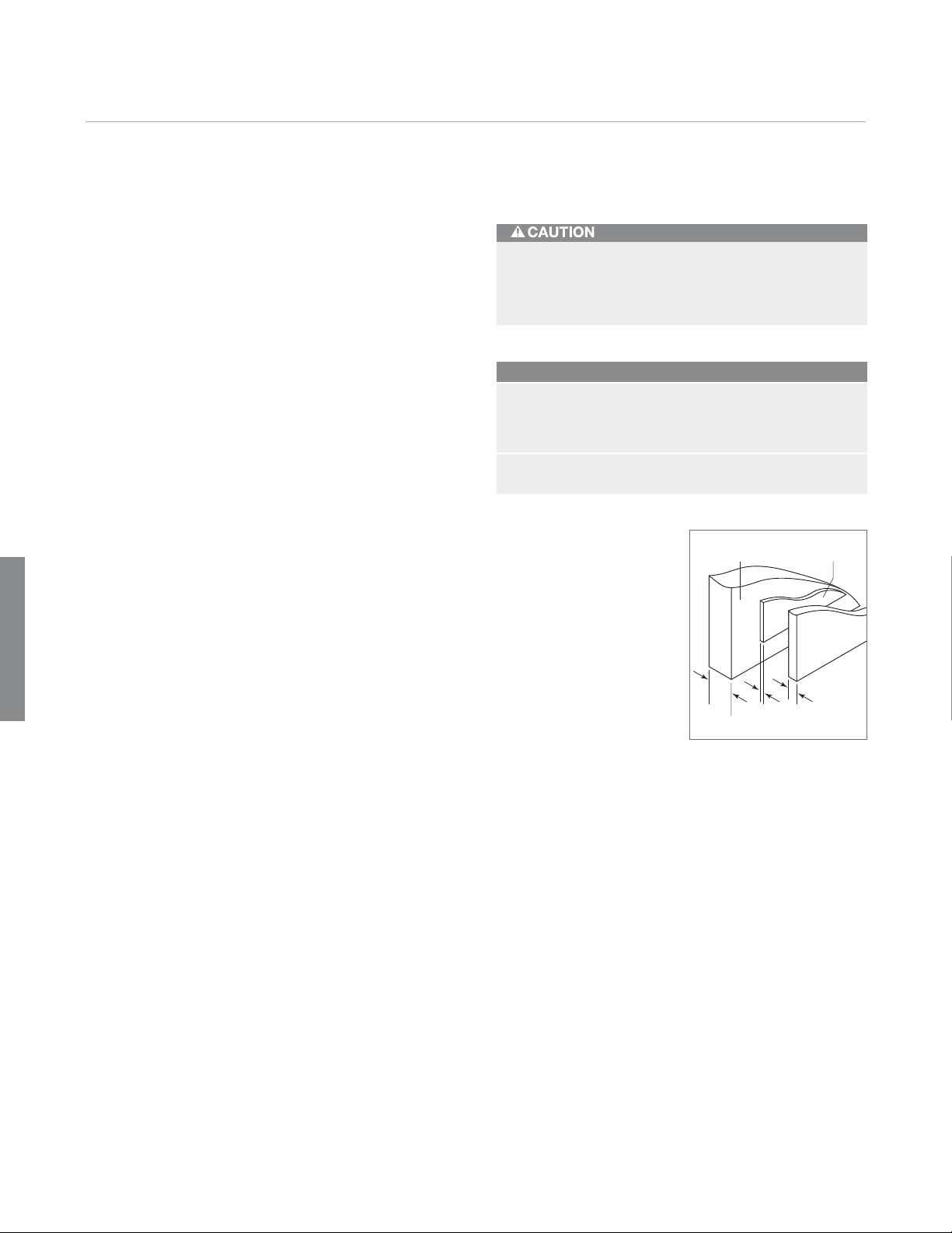
Dispenser Area. For Models BI-42SD and BI-48SD,
the refrigerator door panel must include a cut-out to
accommodate the dispenser glasswell and bezel. The
thickness of the panel in this area can range from
to a maximum of 1
1
/8" (29).
IMPORTANT NOTE: Regardless of the thickness of the
panel for Model BI-42SD or BI-48SD, you must plan for a
flat landing area for the decorative bezel surrounding the
glasswell area. The illustration to the right provides exact
bezel dimensions. Refer to the appropriate panel specifications page for exact cut-out location. This landing area
can be accomplished in a number of different ways.
These photos show two options.
One option (flush) is to rout the panel so the bezel will be
flush with rails and stiles. You must rout a space to
accommodate the height and width of the bezel. The
width of the stile immediately adjacent to the bezel must
7
be 1
/16" (37). Do not cut the entire stile to this dimen-
sion.
The other option (proud) shows a boxed out landing area
for the bezel using stiles and rails to create this space. In
this application, the bezel will sit proud of the stiles and
rails. The total thickness of the panels at this level must
not exceed 1
1
/8" (29).
For overlay and flush inset Models BI-42SD and BI-48SD,
mounting placement of the refrigerator door handle must
assure proper access to the glasswell and adequate
clearance under the handle. The handle placement illustration shows the relation of the refrigerator door handle
to the glasswell bezel on stainless steel models.
1
/4"(6)
Flush option.
5
/8"
(16)
65/16" (160)
127/8"
(327)
Dispenser dimensions.
Proud option.
3
/32"
(2)
1"
(25)
1
/8" (3)
radius
Handle placement.
2"
(51)
Glasswell
Profile
Handle
Profile
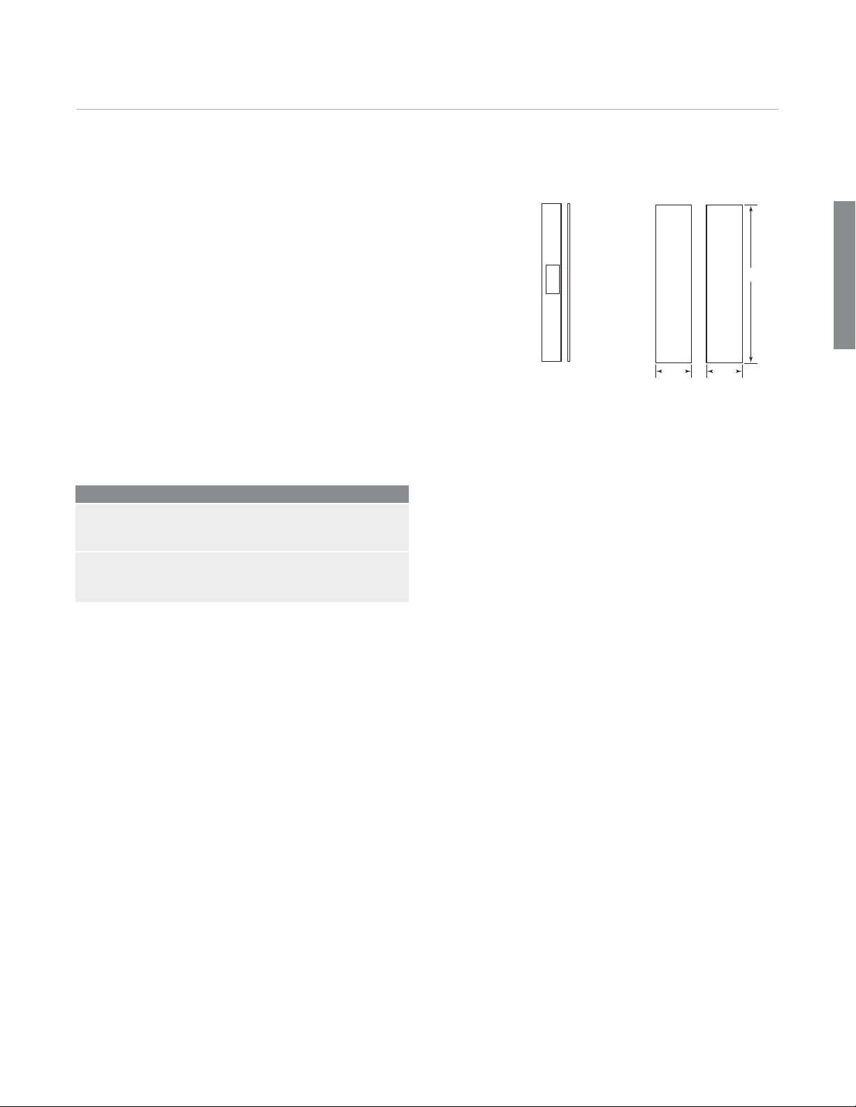
Page 29

Side Panels 29
subzerotrade.com
Side Panels. Side panels can be used with all framed,
overlay, flush inset and stainless steel design applications. When planning for side panels with the installation
of a built-in model, you need to be aware of the space
configuration to achieve a pleasing fit. Depending on the
exact panel you are using with your unit, the height of the
panel may vary.
IMPORTANT NOTE: The use of side panels may change
the width of your rough opening.
When installing a built-in unit with a custom side panel,
an accessory kit (7003407) is required. Classic stainless
steel and white enamel side panels are also available
through your Sub-Zero dealer.
The side panel will need to be a minimum of 24" (610)
deep and
sions illustration for additional specifications. Routing will
be necessary in order for the side panel to fit flush
against the side of the unit. Refer also to the routing
detail illustration.
IMPORTANT NOTE: If you have a Model BI-30U, BI-30UG,
BI-36U or BI-36UG, extra routing will be necessary to
avoid having the panel hit the refrigerator lower hinge
plate.
1
/2" (13) thick. Refer to the side panel dimen-
24" (610)
FRONT
OF SIDE
PANEL
1
ROUT TO
/8" (3)
17/8"(48)
1" (25)
41/4" (108)
ROUT TO
3
/16" (5)
(OVER-AND-UNDER
MODELS)
4" (102)
OPTIONAL
TOE KICK
CUT-OUT
53/4"
(146)
201/2"
(521)
Side panel dimensions.
(2134)
25/8"
(67)
84"
1" (25)
1
/8" (3)
1
/2" (13)
MAIN
FRAME
Routing Detail.
17/8" (48)
SIDE PANEL
ROUTING
Page 30

Dual Installations 30
Dual Standard Installations. Two framed, overlay
or stainless steel units may be placed side by side in a
dual installation. Some dual standard installations will
require a dual installation kit, available through your
Sub-Zero dealer. If you are installing two units side by
side in a flush inset application refer to page 33.
A custom filler strip can be used in between two units in a
framed, overlay or stainless steel design application. It is
recommended that the filler strip be at least 2" (51) wide,
to prevent condensation between the units. Be sure to
add the filler strip width to your rough opening width.
Refer to the full-scale template on page 41.
Dual installations without a filler strip can only be accomplished using two units with opposite hinges as shown in
illustration A below. The dual installations shown in illustrations B and C require a filler strip.
Dual Installations
Dual Standard Installation
Dual Installation Panel Requirements
MAX WEIGHT PER PANEL
BI-36R, BI-36RG and BI-36F 75 lbs (34 kg)
All Other Models 50 lbs (23 kg)
Dual Wide Grille Panel 26 lbs (12 kg)
MIN PANEL THICKNESS
Framed Panels
Overlay and Flush Inset Panels
1
/4" (6)
5
/8" (16)
IMPORTANT NOTE: For the application shown in illustra-
tion A, a dual installation accessory kit is required. Refer
to page 36 for information on dual installation accessory
kits.
WITHOUT FILLER STRIP
Illus. A
FILLER STRIP REQUIRED
FILLER STRIP REQUIRED
Illus. B Illus. C
Page 31

Dual Installations 31
subzerotrade.com
Dual Standard Installation Opening Dimensions
Framed, Overlay and Classic Stainless Steel Models
TOP VIEW
24" (610)
OPENING
24" (610)
OPENING DEPTH
DEPTH
OUTLINE
OF TWO UNITS WITH
3
/4" (19) PANEL
833/4"
(2127)
OPENING
HEIGHT
83" min
(2108)
Opening Widths A
Two 30" (762) Models 593/4" (1518)
Two 36" (914) Models 713/4" (1822)
A
OPENING WIDTH
FRONT VIEWSIDE VIEW
IMPORTANT NOTE: A dual installation kit will be required for
this installation.
Classic stainless steel models are ready to install out of the
box.
Dual Installations
Page 32
Dual Installations 32
Dual Flush Inset Installation. Installing two built-in
models side by side in a flush inset application will require
adjustments to the dimensions of your finished rough
opening, panel sizes and panel offsets. It will also require
a dual installation kit, available through your Sub-Zero
dealer.
Dual installations without a filler strip can only be accomplished using two units with opposite hinges as shown in
illustration A below. The dual installations shown in illustrations B and C require a filler strip. Illustration A is the
only application that will accommodate the dual wide grille.
IMPORTANT NOTE: The application shown in illustration A
can only be achieved by installing dual flush inset panels.
Failure to install dual flush inset panels will cause the
handle side of the panels to collide when closing. In this
application a dual installation accessory kit is also
required.
Dual Installations
Dual Flush Inset Installation
Dual Installation Panel Requirements
MAX WEIGHT PER PANEL
BI-36R, BI-36RG and BI-36F 75 lbs (34 kg)
All Other Models 50 lbs (23 kg)
Dual Wide Grille Panel 26 lbs (12 kg)
MIN PANEL THICKNESS
Flush Inset Panels
5
/8" (16)
Dual flush inset panels and dual installation kits are available through your Sub-Zero dealer. Refer to pages 34–35
for dual flush inset panel specifications and page 36 for
information on dual installation accessory kits.
WITHOUT FILLER STRIP
Illus. A
FILLER STRIP REQUIRED FILLER STRIP REQUIRED
Illus. B Illus. C
Page 33
Dual Installations 33
11/4"
(32)
24"
(610)
OPENING
DEPTH
TO CLEAT
CLEAT
TOP VIEW
263/16"
(665)
FLUSH
INSET
DEPTH
23/16"
(56)
3"
(76)
typical
24"
(610)
OPENING
DEPTH TO
CLEAT
11/4"
(32)
23/16"
(56)
CLEAT
SHADED
AREA
MUST BE
FINISHED
3"
typical
(76)
4"
(102)
subzerotrade.com
Dual Flush Inset Installation Opening Dimensions
TOP VIEW
610)
24" (
263/16"
DEPTH
(665)
TO CLEAT
FLUSH
CLEAT
24" (610)
DEPTH TO CLEAT
263/16" (665)
FLUSH INSET DEPTH
23/16"
(56)
INSET
DEPTH
1
/4"
(6)
23/16"
(56)
11/4"
(32)
OUTLINE OF
TWO UNITS WITH
3
/4" (19) PANEL
CLEAT
DETAIL A
Detail A
833/4"
(2127)
HEIGHT
TO CLEAT
83" min
(2108)
(2134)
FLUSH
INSET
HEIGHT
84"
11/4"
(32)
SIDE VIEW
Opening Widths A B
Two 30" (762) Models 593/4" (1518) 621/4" (1581)
Two 36" (914) Models 713/4" (1822) 741/4" (1886)
A
WIDTH TO CLEAT
B
FLUSH INSET WIDTH
FRONT VIEW
IMPORTANT NOTE: Dimensions assume a3/4" (19) panel
thickness. A dual installation kit will be required for this
installation.
DETAIL B
11/4"
(32)
Detail B
Dual Installations
Page 34
Dual Installations 34
Dual Installations
Flush Inset Panels—Dual Installation. When
installing two built-in models side by side in a flush inset
application, you must decrease the width of the decorative flush inset panels by
offsets will also need to be made. These adjustments are
needed to achieve a proper fit and to ensure the panels
do not collide when closing. Panel dimensions in the
chart below have been adjusted to reflect the decrease in
panel dimensions.
IMPORTANT NOTE: If a filler strip is not used, dual instal-
lations can only be accomplished using two units with
opposite hinges.
Illustrations A–F provide panel offsets and reveals for all
built-in models in a flush inset application. Refer to the
chart below for reference to the illustrations relating to
your specific model. All reveals are
wise specified.
For additional information on model specific panel
reveals, visit the Specification Library section of our
website, subzerotrade.com.
Panel Offsets Illus.
ALL REFRIGERATOR / ALL FREEZER
Doors (hinge) / Grille Sides A
Doors (handle) Sides B
Grille Top C
Grille Bottom / Door Top D
Door Bottom F
OVER-AND-UNDER
Doors (hinge) / Drawer / Grille Sides A
Doors (handle) Sides B
Grille Top C
Grille Bottom / Door Top D
Door Bottom / Drawer Top E
Drawer Bottom F
1
/2". Adjustments to the panel
1
/2" (13) unless other-
5
/16" (8)
TOP VIEW
CABINETRY
1
/2"
(13)
5
/8"
(16)
DOOR DOOR
5
/16" (8)
1
DOOR / DRAWER / GRILLE
BACKER
SPACER
FLUSH INSET PANEL
Illus. A Illus. B
CABINETRY
1
GRILLE
1
5
/16"
(8)
SIDE VIEW
/8"
(3)
/2"(13)
GRILLE
DOOR
Illus. C Illus. D
5
/16"
3
(8)
/32"
5
/16"
(8)
SIDE VIEW
(2)
5
/8"(16)
5
/32"
(4)
DOOR
DRAWER
/8" (3)
DOOR /
DRAWER
TOP VIEW
DUAL
TRIM
SIDE VIEW
1
/4" (6)
REVEAL
5
/16"
5
(8)
3
5
/16"
(8)
SIDE VIEW
5
/32"
(4)
/32"
(2)
/16"
(8)
1
/2"(13)
3
/32"
(2)
Do not exceed the flush inset decorative panel
dimensions. Exceeding dimensions could cause
damage to the panels and the Sub-Zero unit.
Illus. E Illus. F
Page 35
Dual Installations 35
subzerotrade.com
Flush Inset Panel Specifications—Dual Installation
HH
A
A A
H
B
W
W
H
W
H H
B
A A
H
B
H
W
H
H
BI-36R / BI-36F BI-36RG BI-30U / BI-36U BI-30UG / BI-36UG
Models BI-36R, BI-36RG and BI-36F
REFRIGERATOR/FREEZER W H
Flush Inset Panel 361/2" (927) 693/4" (1772)
Spacer Panel 351/8" (892) 6815/16" (1751)
Backer Panel 353/4" (908) 699/16" (1767)
GRILLE W H
Flush Inset Panel 361/2" (927) 91/4" (235)
Spacer Panel 351/8" (892) 85/16" (211)
Backer Panel 353/4" (908) 815/16" (227)
BI-36RG W H
Window Cut-Out 251/2" (648) 541/8" (1375)
AB
Cut-Out Location 53/4" (146) 103/8" (264)
Models BI-36U and BI-36UG
REFRIGERATOR W H
Flush Inset Panel 361/2" (927) 501/8" (1273)
Spacer Panel 351/8" (892) 495/16" (1253)
Backer Panel 353/4" (908) 4915/16" (1268)
FREEZER W H
Flush Inset Panel 361/2" (927) 19" (483)
Spacer Panel 351/8" (892) 181/16" (459)
Backer Panel 353/4" (908) 1811/16" (475)
GRILLE W H
Flush Inset Panel 361/2" (927) 91/4" (235)
Spacer Panel 351/8" (892) 85/16" (211)
Backer Panel 353/4" (908) 815/16" (227)
BI-36UG W H
Window Cut-Out 251/2" (648) 395/8" (1006)
Models BI-30U and BI-30UG
REFRIGERATOR W H
Cut-Out Location 53/4" (146) 51/4" (133)
Flush Inset Panel 301/2" (775) 501/8" (1273)
Spacer Panel 291/8" (740) 495/16" (1253)
Backer Panel 293/4" (756) 4915/16" (1268)
FREEZER W H
Flush Inset Panel 301/2" (775) 19" (483)
Spacer Panel 291/8" (740) 181/16" (459)
Backer Panel 293/4" (756) 1811/16" (475)
GRILLE WH
Grille panel dimensions listed are for a standard 84" (2134)
overall height of the unit. For an 83" (2108) overall height,
subtract 1" (25) from grille panel height dimensions. For an
88" (2235) overall height, add 4" (102) to height dimensions.
Width dimensions do not vary.
For dual wide grilles, refer to page 36.
Flush Inset Panel 301/2" (775) 91/4" (235)
Spacer Panel 291/8" (740) 85/16" (211)
Backer Panel 293/4" (756) 815/16" (227)
BI-30UG W H
Window Cut-Out 191/2" (495) 395/8" (1006)
AB
Cut-Out Location 53/4" (146) 51/4" (133)
Dual Installations
AB
Page 36

Dual Installations 36
Dual Installation Kit with Dual Wide Grille.
This kit will replace the existing grilles that ship with the
units and span the entire width of both units. The kit
1
includes a
/4" (6) center trim strip (required for proper
installation of the dual wide grille), heater, dual kickplate
and mounting hardware. Dual wide grilles are available for
all built-in models and design applications. The overlay
dual installation kit with grille will accept overlay and dual
flush inset panels. For dual wide grille panel dimensions,
refer to the panel specifications below for your design
application. Grille panel dimensions listed are for a
standard 84" (2134) overall height of the unit.
Dual Wide Grille—Overlay Panels
Two 30" (762) Models
DUAL WIDE GRILLE W H
Overlay Panel 601/4" (1530) 91/4" (235)
Spacer Panel 593/8" (1558) 85/16" (211)
Backer Panel 60" (1524) 815/16" (227)
Dual Wide Grille—Flush Inset Panels
Dual Installation Kit. This kit is available for those
who choose to utilize the individual grilles that ship with
each unit. The kit includes a
the reveal between the units and grilles), heater and
mounting hardware. This dual installation kit is not
required if a custom filler strip is used. The filler strip
should be a minimum of 2" (51) wide. Refer to full-scale
template on page 41 for more information.
Two 36" (914) Models
DUAL WIDE GRILLE W H
Overlay Panel 721/4" (1835) 91/4" (235)
Spacer Panel 713/8" (1813) 85/16" (211)
Backer Panel 72" (1829) 815/16" (227)
1
/4" (6) filler strip (which fills
Dual Installations
Two 30" (762) Models
DUAL WIDE GRILLE W H
Flush Inset Panel 611/4" (1556) 91/4" (235)
Spacer Panel 593/8" (1558) 85/16" (211)
Backer Panel 60" (1524) 815/16" (227)
Two 36" (914) Models
DUAL WIDE GRILLE W H
Flush Inset Panel 731/4" (1861) 91/4" (235)
Spacer Panel 713/8" (1813) 85/16" (211)
Backer Panel 72" (1829) 815/16" (227)
Page 37

Built-In Accessories 37
subzerotrade.com
Accessories. These optional accessories are available for built-in models. Be aware that some accessories can not be
used with every model. Accessories are available through your Sub-Zero dealer. To obtain local dealer information, visit
the Showroom Locator section of our website, subzero.com.
• Front panels for framed design in white and classic
stainless steel—not available for glass door models.
• Front panels for flush inset application in classic,
platinum and carbon stainless steel with tubular,
curved and pro handles.
• Louvered, panel and stainless steel grilles for 83"
(2108) and 88" (2235) overall heights. Built-in models
come standard with a grille for an 84" (2134) overall
height of the unit.
• Side panels in white and classic stainless steel.
• Custom side panel mounting kit.
• Extended framed handles for framed models with
raised panels.
• Decorative stainless steel handles available in tubular,
curved and pro styles in a variety of lengths. For
standard handle lengths, refer to the chart.
• Retrofit kits for use with 600 series panels. Allows for
existing 600 series panels to be used on a new built-in
model—not available for Models BI-36R, BI-36RG, BI36F, BI-30UG, BI-36UG, BI-42SD and BI-48SD.
Standard Handle Lengths
ALL REFRIGERATOR / ALL FREEZER / SIDE-BY-SIDE MODELS
Tubular Handle 637/8" (1622)
Pro Handle 451/8" (1146)
Curved Handle 575/8" (1464)
Stud Spacing 437/8" (1114)
BI-30U and BI-30UG DOOR DRAWER
Tubular Handle 441/4" (1124) 245/16" (633)
Pro Handle 371/2" (952) 21" (533)
Curved Handle 453/16" (1148) 251/4" (641)
Stud Spacing 361/4" (921) 165/16" (414)
BI-36U and BI-36UG DOOR DRAWER
Tubular Handle 441/4" (1124) 305/16" (770)
Pro Handle 371/2" (952) 231/2" (597)
Curved Handle 453/16" (1148) 311/4" (796)
Stud Spacing 361/4" (921) 225/16" (567)
• Dual installation kit for use when placing units side by
side. Kits available with or without the dual wide grille
assembly.
• Partial framed kit for dispenser Models BI-42SD and
BI-48SD. Includes a stainless steel trim piece to be
used above and below the dispenser.
Page 38
Panel Thickness and Handle Profile 38
OPTIONAL EXTENDED
FULL-LENGTH HANDLE
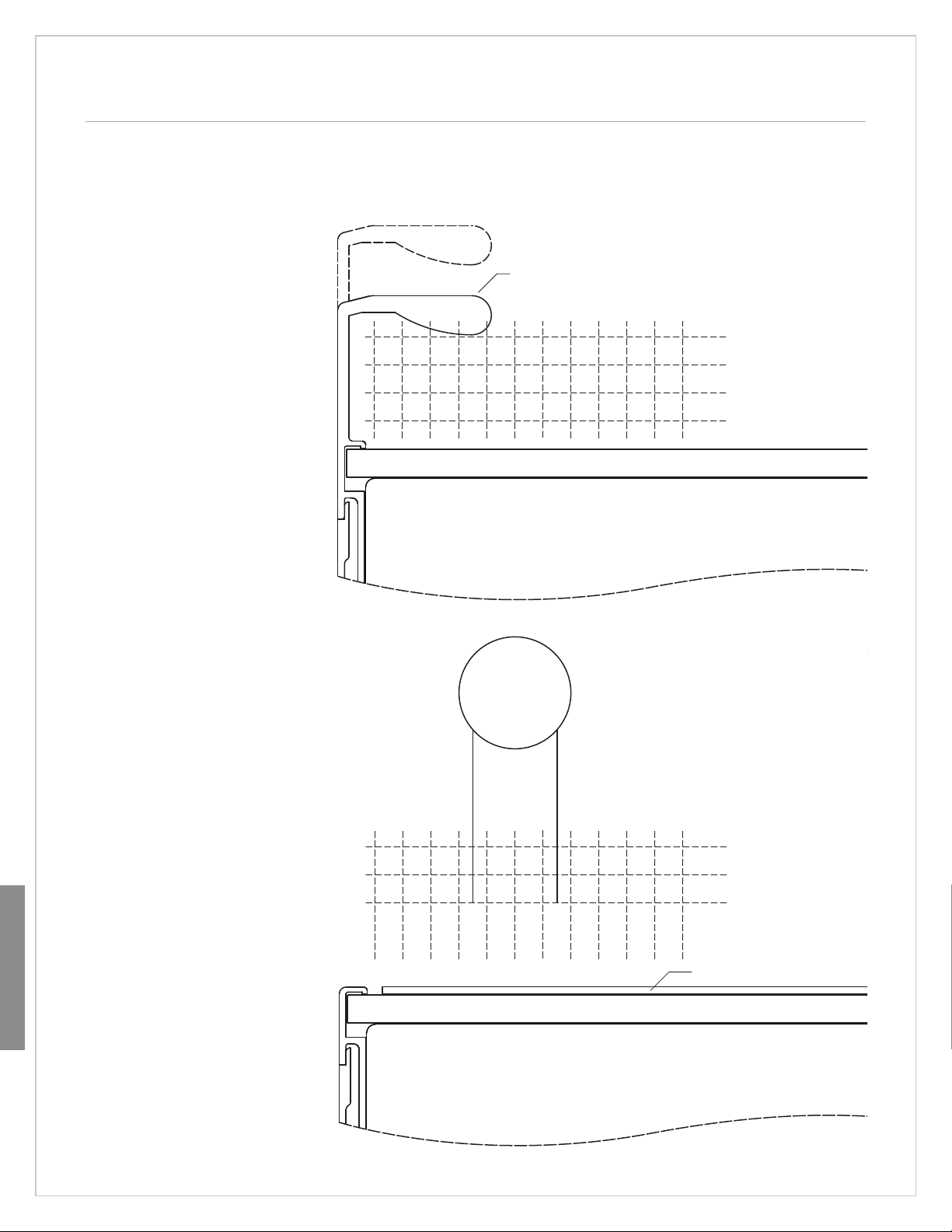
Framed. The top full-scale
template shows handle placement and panel thickness for
framed applications.
1"
(25)
1
/4" (6) FRAMED PANEL
STANDARD
FULL-LENGTH HANDLE
2"
(51)
DOOR
3"
(76)
11/4" (32) PANEL
1" (25) PANEL
3
/4" (19) PANEL
1
/2" (13) PANEL
Full-Scale Templates
Overlay and Flush Inset.
The bottom full-scale template
shows handle placement and
panel thickness for overlay and
flush inset applications.
IMPORTANT NOTE: Panel thickness does not include the
backer panel and .10" (3) spacer
panel.
IMPORTANT NOTE: The panel
must be a minimum of
thick to support mounting the
handle hardware.
Mount door handles close to the
opening edge of the door for
ease of opening.
1
/4"(6)
5
/8"(16)
1"
(25)
1
/4" (6) BACKER PANEL
DOOR
DEPTH OF TUBULAR, CURVED
AND PRO HANDLES
2"
(51)
3"
(76)
11/4" (32) PANEL
1" (25) PANEL
3
/4" (19) PANEL
.10" (3) SPACER PANEL
Page 39
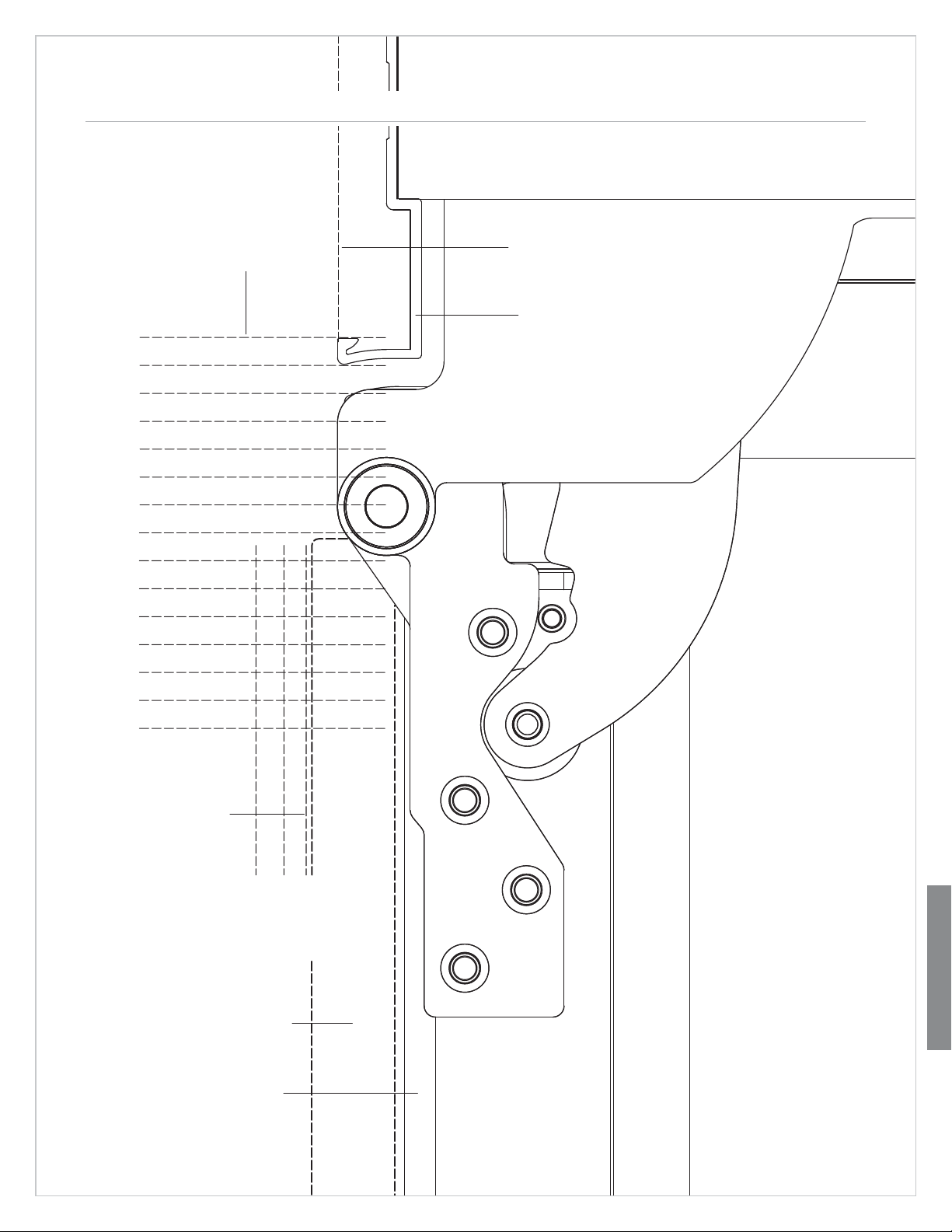
Overlay Panel Application—90° Door Opening 39
SUB-ZERO UNIT
237/8" (606)
TO REAR OF UNIT
(0)
0"
1
(6)
"
4
/
1
(13)
"
2
/
3
(19)
"
4
/
(25)
1"
1
(32)
"
4
/
1
1
(38)
"
2
/
1
3
(44)
"
4
/
1
(51)
2"
1
(57)
"
4
/
2
1
(63)
"
2
/
2
3
(70)
"
4
/
2
OVERALL WIDTH
OF UNIT
MAIN FRAME
subzerotrade.com
DOOR CLOSED
TOP VIEW
(76)
3"
1
(83)
"
4
/
3
1
(89)
"
2
/
3
APPROX THICKNESS
OF WRAPPED STAINLESS
STEEL DOOR
(32) PANEL
"
4
/
1
1
OVERLAY PANEL
3
/4" (19) THICK
(TYPICAL)
1
4"(6)
/
PA N
EL
(25) PANEL
1"
(19) PANEL
"
4
/
3
DOOR OPEN 90˚
This full-scale template
shows what considerations
you need to make for
overlay panel applications
and how they may interact
with adjacent cabinets and
countertops.
Full-Scale Templates
Page 40
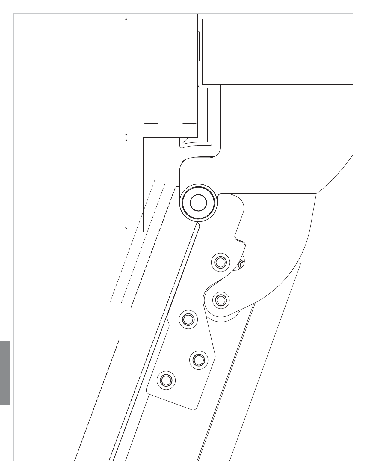
Flush Inset Panel Application—110° Door Opening 40
SUB-ZERO UNITCABINETRY
This full-scale template
shows what considerations
you need to make for flush
inset panel applications and
how they may interact with
adjacent cabinets and
countertops.
IMPORTANT NOTE: For
flush inset panels thicker
3
than
/4" (19), a 90˚ door
stop may be needed to
avoid interference with
adjacent cabinets.
Dimensions in parentheses
are in millimeters unless
otherwise specified.
24" (610)
TO BACK WALL
23/16" (56)
ASSUMES
3
/4" (19)
FLUSH INSET
PANEL
THICKNESS
11/4" (32)
MAIN FRAME
Full-Scale Templates
FLUSH INSET PANEL
3
/4" (19) THICK
(TYPICAL)
4
/
1
1
(32)PANEL
"
1
PA NE L
1"
4
/
(25)PANEL
(6)
"
3
(19)PANEL
"
4
/
TOP VIEW
DOOR OPEN 110˚
Page 41
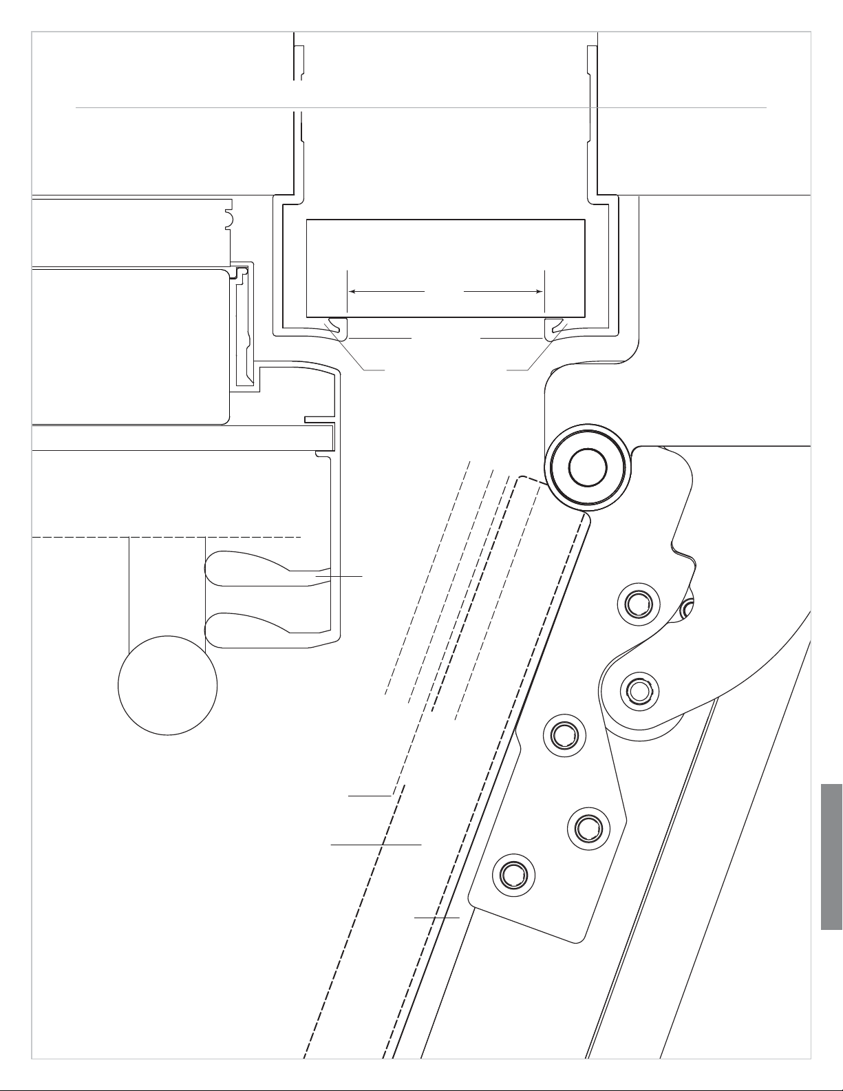
Panel and Handle Profile—110° Door Opening 41
subzerotrade.com
TOP VIEW
FILLER STRIP
2" (51)
SUB-ZERO UNITSUB-ZERO UNIT
DOOR CLOSED
APPROX PROFILE OF
STAINLESS STEE WRAPPED
DOOR AND HANDLE
This full-scale template
shows the panel and handle
profile for a dual installation
with a 2" (51) filler strip at
110˚ door opening.
Interference of door panels
with handles at maximum
door opening may require
the use of an optional 90˚
door stop available through
your Sub-Zero dealer.
Dimensions in parentheses
are in millimeters unless
otherwise specified.
OPTIONAL
FRAMED EXTENDED
FULL-LENGTH HANDLE
APPROX THICKNESS OF
WRAPPED STAINLESS
STEEL DOOR
OVERLAY PANEL
3
/4" (19) THICK
(TYPICAL)
MAIN FRAME
ALLOW FOR FILLER LAP
BEHIND FLANGE
STANDARD
FRAMED
FULL-LENGTH
HANDLE
(25) PANEL
1"
"
4
/
PA N
(19)
"
4
/
3
(6)
"
4
/
1
1
(32) PANEL
1
PA NEL
EL
(13) PANEL
"
2
/
1
Full-Scale Templates
DOOR OPEN 110˚
Page 42

Sub-Zero Products Limited Warranty
RESIDENTIAL USE ONLY
FULL FIVE YEAR SEALED SYSTEM WARRANTY
LIMITED SIXTH THROUGH TWELFTH YEAR WARRANTY ON THE SEALED SYSTEM
FULL TWO YEAR WARRANTY ON TOTAL PRODUCT*
FULL FIVE YEAR SEALED SYSTEM WARRANTY
For five years from the date of original installation, your Sub-Zero warranty covers all parts and labor to repair or
replace any components that prove to be defective in materials or workmanship in the sealed system.The sealed
system consists of the compressor, condenser, evaporator, drier and all connecting tubing.
FULL TWO YEAR WARRANTY*
For two years from the date of original installation, your Sub-Zero warranty covers all parts and labor to repair or
replace any part of the product, that proves to be defective in materials or workmanship.
LIMITED SIXTH THROUGH TWELFTH YEAR SEALED SYSTEM WARRANTY
From the 6th through the 12th year from the date of original installation, your Sub-Zero warranty covers all parts
that prove to be defective in materials or workmanship in the sealed system (parts only). The sealed system
consists of the compressor, condenser, evaporator, drier and all connecting tubing.
TERMS APPLICABLE TO EACH WARRANTY
All service provided by Sub-Zero under the above warranty must be performed by an authorized Sub-Zero service
center, unless otherwise specified by Sub-Zero. Service will be provided in the home during the normal business
hours. This warranty applies only to products installed for normal residential use. Details regarding a non-residential warranty are available upon request.
The warranty applies only to products installed in any one of the fifty states of the United States, the District of
Columbia or the ten provinces of Canada. This warranty does not cover any parts or labor to correct any defect
caused by negligence, accident or improper use, maintenance, installation, service or repair, including but not
limited to improper removal and reinstallation (whether in the unit or at a remote location) of the condensing unit.
THE REMEDIES DESCRIBED ABOVE FOR EACH WARRANTY ARE THE ONLY ONES THAT SUB-ZERO WILL
PROVIDE, EITHER UNDER THESE WARRANTIES OR UNDER ANY WARRANTY ARISING BY OPERATION OF
LAW. SUB-ZERO WILL NOT BE RESPONSIBLE FOR ANY CONSEQUENTIAL OR INCIDENTAL DAMAGES ARISING FROM THE BREACH OF THESE WARRANTIES OR ANY OTHER WARRANTIES, WHETHER EXPRESS,
IMPLIED OR STATUTORY.
Some states do not allow the exclusion or limitation of incidental or consequential damages, so the above limitation or exclusion may not apply to you. This warranty gives you specific legal rights and you may also have other
legal rights, which vary from state to state.
To receive parts and/or service and the name of the Sub-Zero authorized service center nearest you, contact your
Sub-Zero dealer, distributor or the Sub-Zero Customer Service Department, P. O. Box 44130, Madison Wisconsin, 53744-4130; check the Contact & Support section of our website, subzero.com, or call 800-222-7820.
*Stainless Steel (classic, platinum and carbon) doors, panels, product frames and stainless interior surfaces are
covered by a limited 60 day parts and labor warranty for cosmetic defects.
*Replacement water filter and air purification cartridges are not covered by the product warranty.
Page 43

©Sub-Zero, Inc. all rights reserved. The information and images in this guide are the copyright property of Sub-Zero, Inc. Neither this guide nor
any information or images contained herein may be copied or used in whole or in part without the express written permission of Sub-Zero, Inc.
Page 44

Sub-Zero, Inc.
PO Box 44130
Madison, WI 53744-4130
800.222.7820
subzero.com
BIDG 6 /2008
 Loading...