

Page 1

INSTALLATION GUIDE
Integrated Refrigeration
Page 2

Contents
Important Note
Integrated Refrigeration . . . . . . . . . . . . . . . . . . . . . . . . . . 3
Model Specifications . . . . . . . . . . . . . . . . . . . . . . . . . . . . 4
Site Preparation . . . . . . . . . . . . . . . . . . . . . . . . . . . . . . . . . 7
Integrated Installation . . . . . . . . . . . . . . . . . . . . . . . . . . . 12
Service Information . . . . . . . . . . . . . . . . . . . . . . . . . . . . . 22
Features and specifications are subject to change at any time
without notice. Visit sub zero.com/specs for the most up- todate information.
IMPORTANT NOTE: Throughout this guide, dimensions in
parentheses are millimeters unless otherwise specified.
o ensure the safe and efficient installation of Sub-Zero
T
equipment, please take note of the following types of
highlighted information throughout this guide:
IMPORTANT NOTE highlights information that is especially
relevant to a problem-free installation.
CAUTION signals a situation where minor injury or product
damage may occur if instructions are not followed.
WARNING states a hazard that may cause serious injury or
death if precautions are not followed.
Page 3
Integrated Refrigeration 3
subzero.com/specs
Sub-Zero Integrated Refrigeration
he importance of th e installation of the Sub-Zero
T
integrated unit c annot be overemphasized. Installation
should be done by a qua lified installer.
Before you begin the installation process, it is recommended that you read this entire installation guide. There
are key details that you should take special care to
observe during th e installation. By reading these instructions carefully, you will make the installation process
easier, problem-free a nd most importantly, safe.
Any questions or problems regarding the installation
should be directed to your authorized Sub-Zero dealer or
Sub-Zero customer care at 800-222-7820. You may also
check the contact & support sectionofour website,
subzero.com.
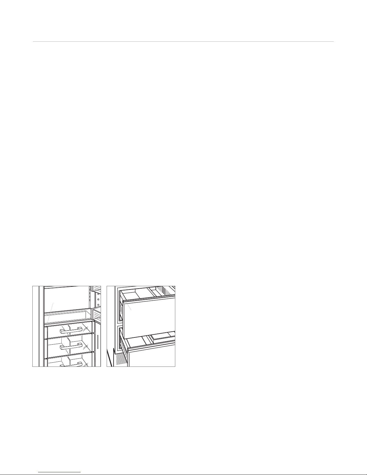
Important product information, including the model and
serial number of yo ur unit are listed on the product rating
plate. For column m odels, the rating plate is located inside
the top drawer near t he drawer guide opposite the hinge.
For tall and drawer m odels, the rating plate is located
inside the cabinet, to the left of the upper drawer. Refer to
the illustrations below.
Before You Start
ake sure the opening dimensions, door and drawer
M
clearances, ele ctrical service and plumb ing are correct for
the model you are about to install. Refer to specifications
on the following pa ges.
IMPORTANT NOTE: The inside edges of the rough
opening, as well as t he sides and a portion of the
backside of the dec orative panels will need to b e finished,
as they will be expos ed when the doors are open.
TOOLS AND MATERIALS REQUIRED
• Appliance dolly a ble to support 500 lbs (227 kg) and
adequate manpower to handle the weight of the unit.
• Phillips and slot ted screwdrivers.
• Allen, standard and crescent wrenches.
• Various sized pli ers.
5
•
/16" hex bolt nut dri ver.
• Cordless drill and assorted drill bits.
• Level—2' (.6 m) and 4' (1.2 m) recommended.
• 4'
(1.2 m) of
PEX tubing and sadd le valve for water line (do not use
self-piercing valves).
1
/4" copper, braided stainless steel or
RATING PLATE
• Tubing cutter.
• Masonite, plywo od, pressed fiberboard, cardboard or
RATING PLATE
other suitable ma terial to protect finished flooring.
• Appropriate materials to cover and protect the home
and furnishings during in stallation.
Tall and drawer mode ls.Column models.
Page 4
Model Specifications 4
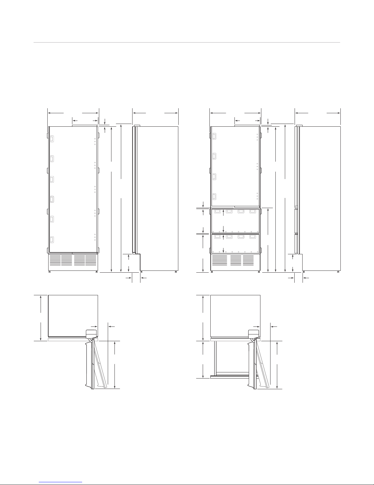
27" (
686)
14"(356)
15/8"
(41)
24"
(610)
81"
(2057)
TO TOPOF
OPENNG
24" (
610)
789/16"
(1995)
93/4"(248)
4"
(102)
1
/2" (13) ± ADJUSTMENT IN LEVELING LEGS
251/2"
(648)
45/8"
(117)
DIMENSIONS WILL VARY WITH PANEL THICKNESS
27" (686)
14"(356)
13
/16"
(21)
341/2"
(876)
24"
(610)
203/8"
(518)
101/4"
(
260)
131/4"
(337)
DIMENSIONS WILL VARY WITH PANEL THICKNESS
1
/2"
(13)
3
/8"
(10)
191/2"
(495)
251/2"
(648)
45/8"
(117)
80"
(2032)
TO TOP OF
OPENNG
24" (610)
789/16"
(
1995)
93/4"
(248)
4"
(102)
HEIGHT DIMENSIONS ±
1
/2" (13)
Overall Dimensions
COLUMN MODELS
27" (6 86) TALL MODE LS
MODELS IC-27R AND IC-27FI
MODELS 700TR, 700TFI AND 700TCI
Page 5
Model Specifications 5
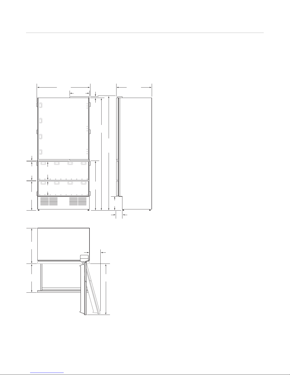
36" (914)
14"(356)
80"
(2032)
TO TOP OF
OPENNG
24" (610)
15/16"
(
33)
7713/16"
(1976)
341/2"
(876)
24"
(610)
203/8"
(518)
101/4"
(260)
131/4"
(337)
93/4"
(248)
4"
(102)
DIMENSIONS WILL VARY WITH PANEL THICKNESS
1
/2"
(13)
3
/8"
(10)
191/2"
(495)
341/2"
(876)
7" (178)
HEIGHT DIMENSIONS ±
1
/2" (13)
subzero.com/specs
Overall Dimensions
36" (9 14) TALL MODE LS
MODELS 736TR, 736TFI AND 736TCI
Page 6
Model Specifications 6
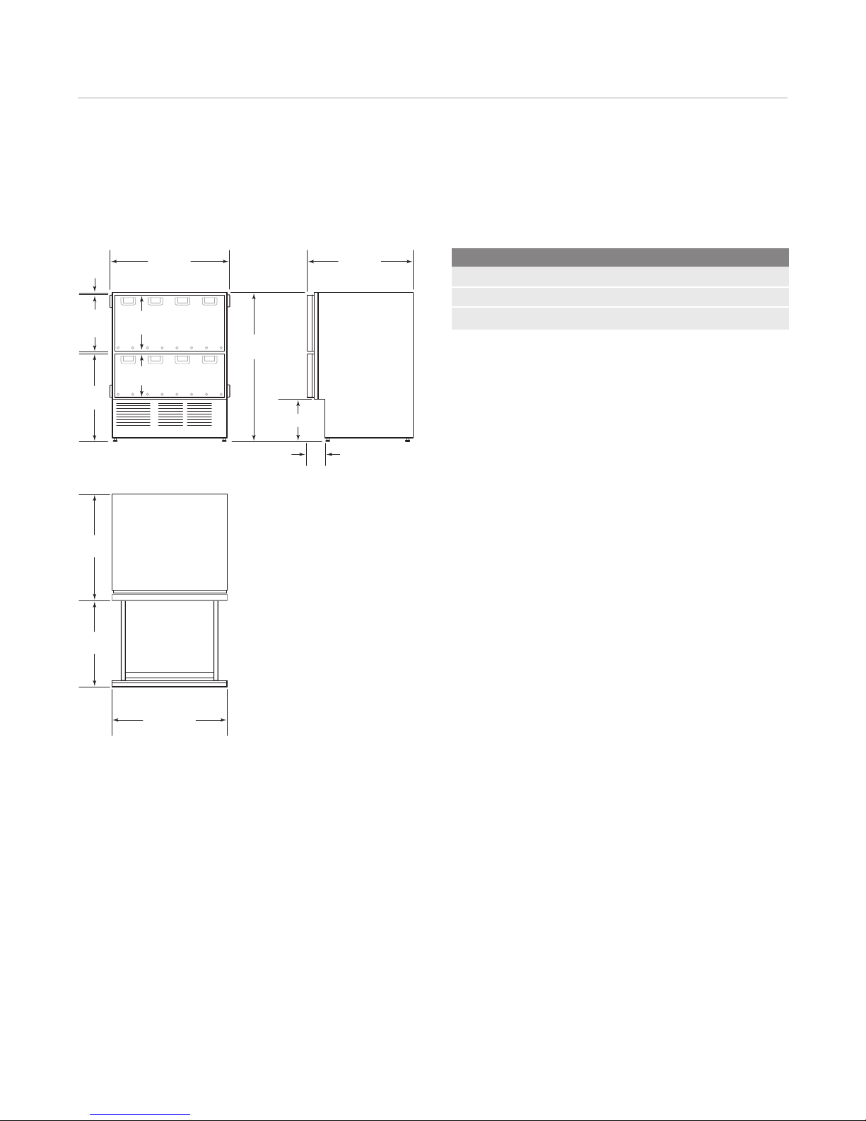
27" (686)
341/2"
(876)
24"
(610)
203/8"
(518)
DIMENSIONS WILL VARY WITH PANEL THICKNESS
1
/2"
(13)
3
/8"
(10)
191/2"
(495)
257/8" (657)
24" (
610)
93/4" (248)
4"
(102)
101/4"
(260)
131/4"
(337)
HEIGHT DIMENSIONS ±
1
/2" (13)
Overall Dimensions
DRAWER MODELS SPECIFICATIONS
Shipping Weight lbs (kg)
IC-27R, IC-27FI, 700TR, 700TFI and 700TCI 360 (163)
736TR, 736TFI and 736TCI 480 (218)
700BR, 700BF(I) and 700BC(I) 190 (86)
MODELS 700BR, 700BF(I) AND 700BC(I)
Page 7
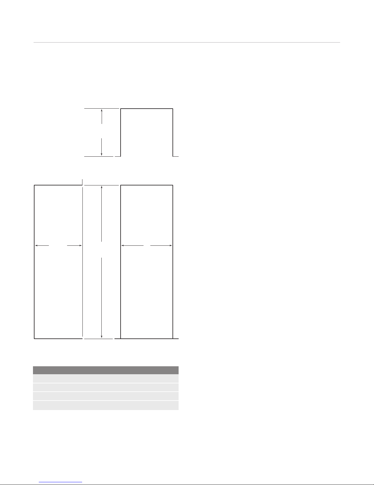
Site Preparation 7
25" (635)
OPENING
DEPTH
A
OPENING WIDTH
25" (
635)
OPENING DEPTH
B
OPENING
H
EIGHT
TOP VIEW
FRONT VIEWSIDE VIEW
subzero.com/specs
Opening Dimensions
INTEGRATED MODELS
IMPORTANT NOTE: The depth of each integ rated model is
24" (610) from the front of the unit to its back. Your design
may necessitate moving th e unit back or cabinets forward to
achieve a flush fit. This will require a minimum rough opening
depth of 25"
(635).
Opening Dimensions AB
700TR, 700TFI, 700TCI 27" (686) 80" (2032)
736TR, 736TFI, 736TCI 36" (914) 80" (2032)
IC-27R and IC-27FI 27" (686) 81" (2057)
700BR, 700BF(I), 700BC(I) 27" (686) 341/2" (876)
Page 8
Site Preparation 8
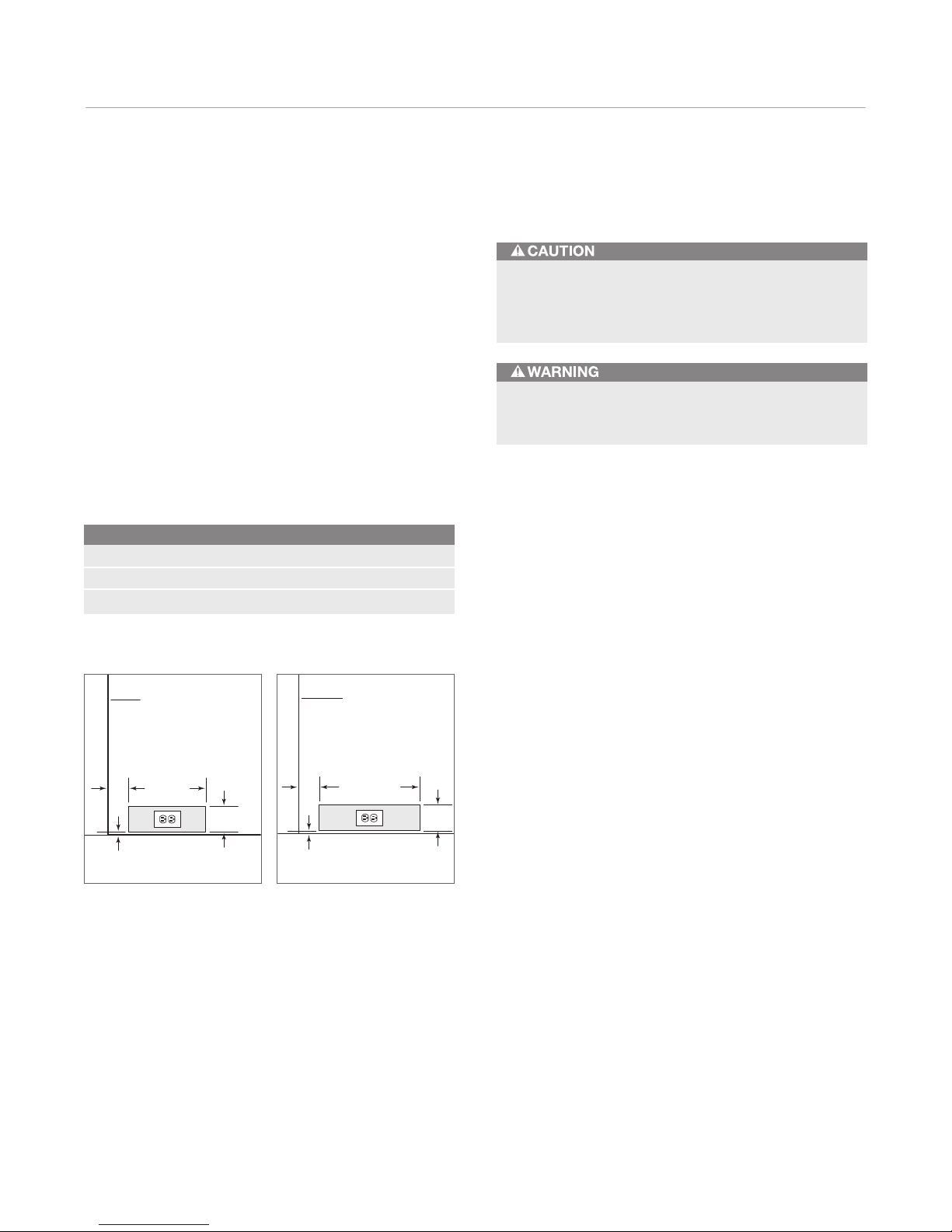
13" (330)
1
/4"
(6)
41/2"
(
114
)
LEFT SIDE
OF OPENING
FLOOR
21/2"
(64)
FRONT VIEW
171/2" (445)
41/2"
(
114
)
FRONT VIEW
FLOOR
1
/4"
(6)
LEFT SIDE
OF OPENING
21/2"
(64)
Electrical Requirements
he electrical sup ply should be located within the shaded
T
area shown in the illustrations below. Follow the National
Electrical Code a nd local codes and ordinances when
installing the receptacle. A separate circuit, servicing only
this appliance is required. A ground fault circuit interrupter
(GFCI) is not recommended and may cause interruption of
operation.
The outlet must be checked by a qualified electrician
to be sure that it is wired with the correct polarity. Verify
that the outlet is properly grounded.
IMPORTANT NOTE: It is critical that the electrical outlet be
located within th e shaded area shown so it does not interfere with installation of the anti-tip bracket. It must be
flush with the back w all and positioned with the grounding
prong to the right of the thinner blades.
Electrical Requirements
Power Supply 115 V AC, 60 Hz
Circuit Breaker 15 amp
Receptacle 3-prong grounding-type
Do not use an extension cord or two-prong adapter.
Do not remove the power supply cord ground prong.
27" (686) models. 36" (914) models.
Page 9
Site Preparation 9
3" (76)
9"
(229)
3
/4"
(19)
FLOOR
21/2" (64)
FRONT VIEW
9"
(229)
6"
(152)
TOP VIEW
11/2"
(38)
21/2" (64)
BACK
WALL
11/2" (38)
131/2"
(343)
3" (76)
FRONT VIEW
3
/4"
(19)
FLOOR
21/2" (64)
1
3
1
/2"
(343)
TOP VIEW
6"
(152)
11/2"
(38)
BACK
WALL
21/2" (64)
11/2" (38)
subzero.com/specs
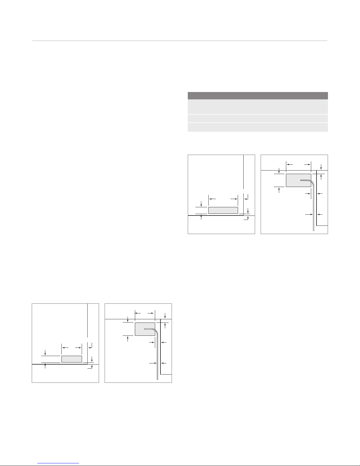
Plumbing Requirements
or integrated mod els with an automatic ice maker, the
F
water supply line s hould be located through the floor o r
back wall, within t he shaded area shown in the illustrations. Routing th e line in these locations will avoid any
interference with the anti-tip bracket.
IMPORTANT NOTE: Do not route the water supply line in
front of the compressor tray. The tray must be slid forward
for service.
The water supply li ne should be connected to the house
supply with an easi ly accessible shut-off valve bet ween
the supply and the un it. Do not use self-piercing valves.
A saddle valve kit is a vailable from your authorized
Sub-Zero dealer.
An in-line filter i s required when water conditions have
a high sediment con tent.
Plumbing Requirements
Water Supply Line
1
/4" OD copper, braided stainless steel
or PEX tubing
Water Pressure 20–100 psi (1.4–6.9 bar)
Excess Water Line for Connection 27" (686)
A reverse osmosis system can be used provided there i s
constant water pressure of 20 psi
(6.9 bar) supplied to the unit at all times. In some cases,
(1.4 bar) to 100 psi
a reverse osmosis water filter system may not be able to
maintain the mini mum pressure consistently. A copper line
is not recommended for this application.
IMPORTANT NOTE: All installations must meet local
plumbing code requirements.
27" (686) models.
36" (914) models.
Page 10
Site Preparation 10
A
A
SUBFLOORING
WOOD FLOOR
WALL PLATE
FINISHED
FLOORING
A
A
SUBFLOORING
CONCRETE
FLOOR
WALL PLATE
FINISHED
FLOORING
11/2"(38)
min
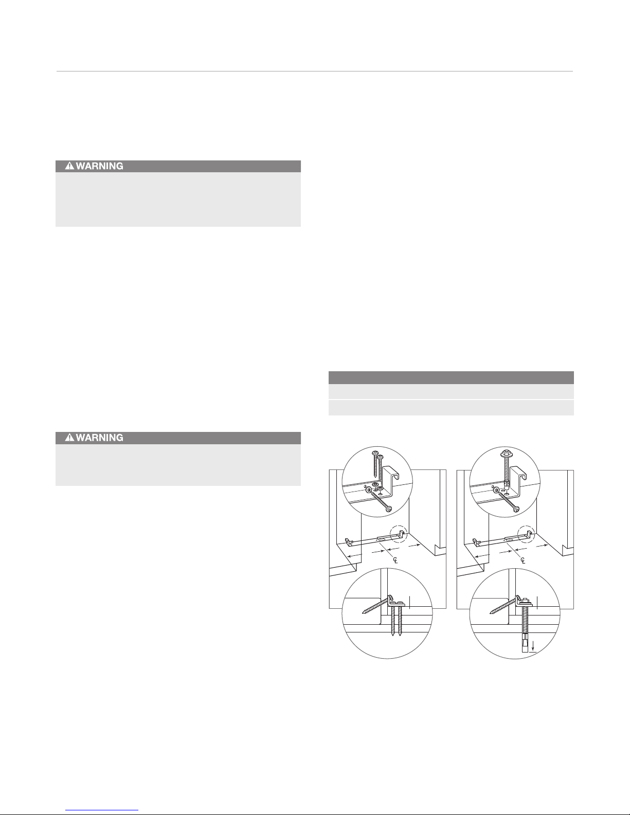
Anti-Tip Bracket Installation
WOOD FLOOR APPLICATIONS
To prevent the unit from tipping forward and provide
a stable installation, the unit must be secured in place
with the anti-tip bracket provided with the unit.
An anti-tip brack et and hardware is provided with the integrated unit. Plac ement of the anti-tip bracket is critical to
a stable installation. The anti-tip bracket must be installed
on a solid base.
If you are installing the unit in a space deeper than 24"
(610), be su re to locate the anti -tip bracket so that it
engages the unit properly. It is important that the anti-tip
bracket is placed 2 4"
(610) from the front of the unit
(without panels) to the back of the anti-tip bracket.
IMPORTANT NOTE: In some installations the subflooring
or finished floor m ay require angling the wood screws
used to fasten the an ti-tip bracket to the back wall.
Make sure there are no electrical wires or plumbing
in the area which the screws could penetrate.
Use the six #12 x 21/2" wood screws and the six1/4" flat
washers provided. Drill pilot holes
3
/16" (5) diameter
maximum, and make s ure the screws penetrate through
the flooring mate rial and into the wall plate a minimum of
3
/4" (19). Make sure the screws hold tight. Re fer to the
illustration be low.
CONCRETE FLOOR APPLICATIONS
Use the two3/8" x 33/4" concrete wedge anchors, two
#12 x 2
1
/2" wood screws and two1/4" flat washers
provided. Make sure the ancho rs and screws hold tight.
Refer to the illustration below.
Anti-Tip Bracket Placement A
27" (686) Models 131/2" (343)
36" (914) Models 18" (457)
Wood floor. Concrete floor.
Page 11
Site Preparation 11
subzero.com/specs
Anti-Tip Bracket Installation
INSTALL CONCRETE WEDGE ANCHORS:
1) Drill a3/8" (10) diameter hole any depth exceeding the
minimum embedment. Clean the hole or continue
drilling additional depth to accommodate drill fines.
Use a carbide drill b it manufactured within ANSI
B94.12-77.
2) Assemble the washer and nut flush with the en d of
anchor to protect threads. Drive the anchor throu gh the
material to be fast ened until the washer is flush with
the surface mater ial.
3) Expand the anchor by tightening the nut 3–5 t urns past
hand-tight posi tion or to 25 foot-pounds of torque.
Always wear safety glasses and use other necessary
protective devices or apparel when installing or
working with anchors.
Anchors are not recommended for use in lightweight
masonry material such as block or brick, or for use in
new concrete which has not had sufficient time to cure.
The use of core drills is not recommended to drill holes
for the anchors.
Position the Unit
Before moving the integrated unit into position, secure
the door closed, remove drawers and protect any
finished flooring.
Uncrate the integ rated unit and inspect for any damage.
Remove the wood bas e and discard the shipping bolts
that hold the wood ba se to the bottom of the unit. Remove
all packing mater ials and tape.
The drawers shoul d be removed and placed aside until
you are ready for installation of the panels. Remove the
decorative top an d side moldings and the kickplate/grille.
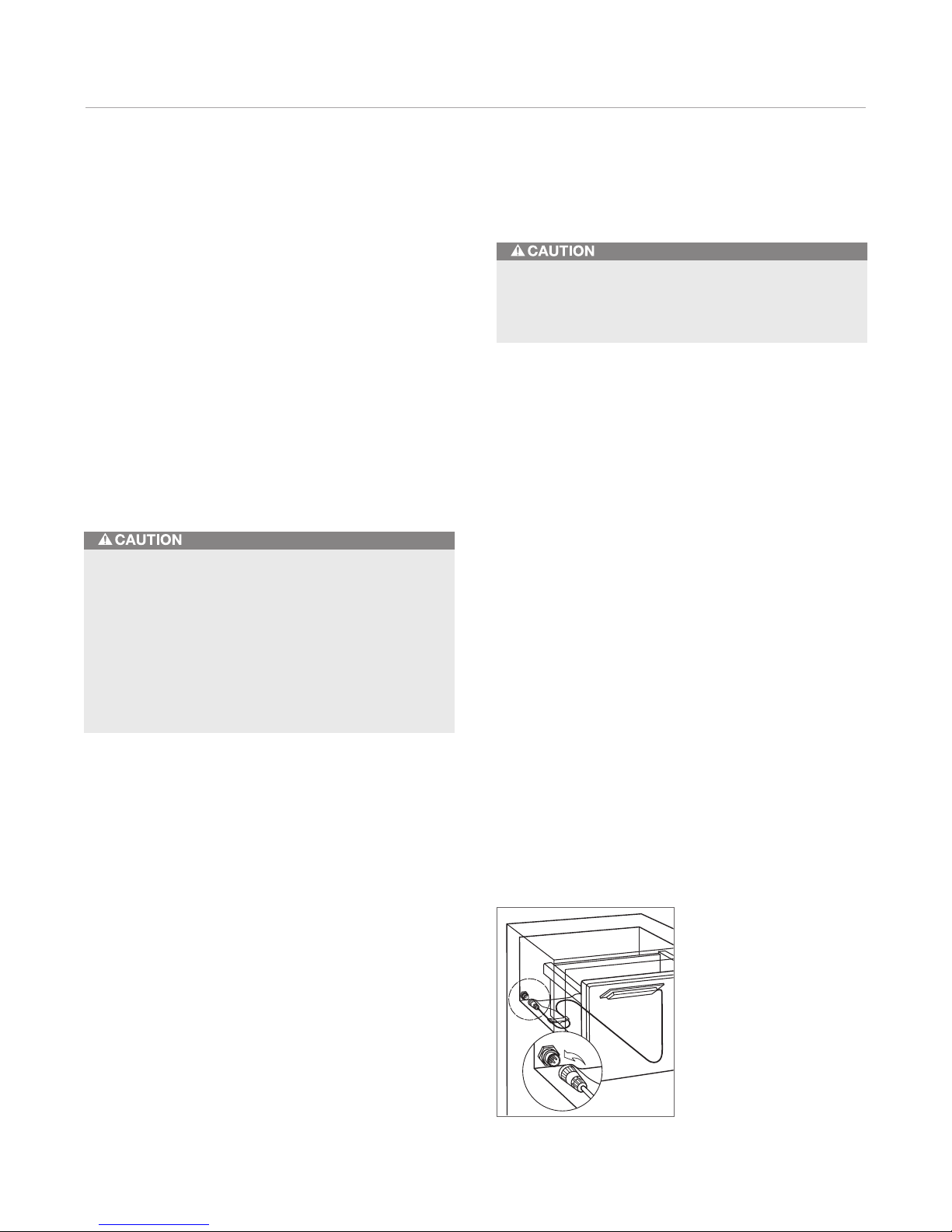
IMPORTANT NOTE: For drawer models, the top drawer
has a control cable that needs to be disconnected before
removing this drawer. Refer to the illustration below for
placement and how t o disconnect this fitting.
Retract the front leveling legs all the way up to allow the
unit to be moved into p osition more easily. You will extend
the leveling legs w hen the unit is in its final position to
reduce the possibility of the unit tipping forward.
Use an appliance do lly to move the integrated unit near
the rough opening. Position the dolly at the side of the unit
to prevent damage to finished surfaces.
IMPORTANT NOTE: If for any reason the integrated unit
has been laid on its ba ck or side, you must allow the unit
to stand upright fo r a minimum of 24 hours before connecting power.
Control cable.
Page 12
Integrated Installation 12
UNIT
ON/OFF
C
O
L
D
E
R
W
A
R
M
E
R
R
E
F
R
I
G
E
R
A
T
O
R
F
R
E
E
Z
E
R
C
O
L
D
E
R
W
A
R
M
E
R
I
C
E
O
N
/
O
F
F
O
N
/
O
F
F
U
N
I
T
O
N
/
O
F
F
UNIT
ON/OFF
Position the Unit
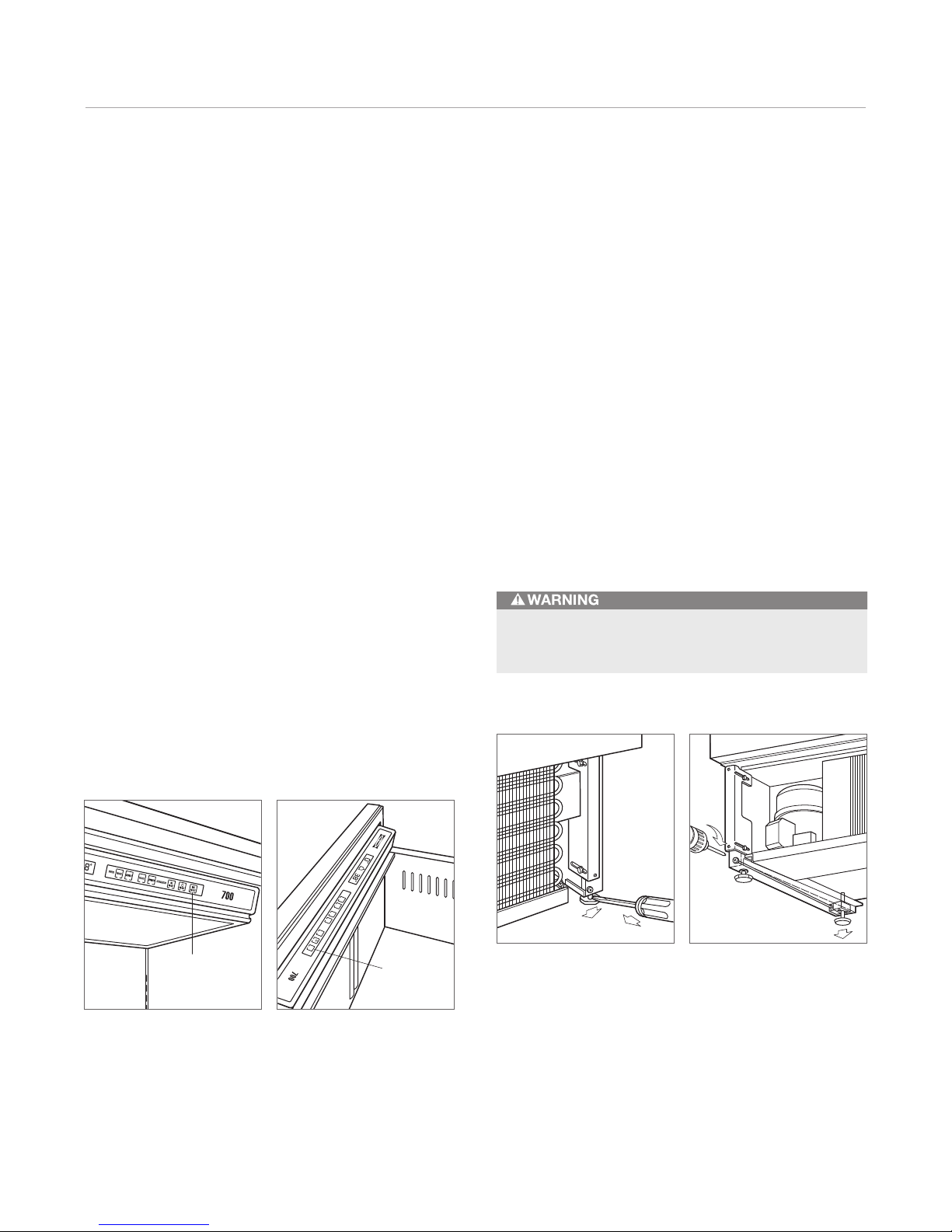
lug the power cord into the grounded electrical outlet.
P
With power applied to the appliance, check for lighting
and cooling. Press the UNIT ON/OFF key pad on the
control panel (POWER for column models). Refer to the
illustrations b elow. Once you are satisfied that the unit is
operating properly, shut off power to the electrical outlet at
the circuit breaker and proceed.
If two integrated u nits are installed closer than 2"
one another, refer to dual installations on page 20.
Pre-level the unit before moving into position. This is to
allow the unit to eng age the anti-tip bracket properly.
Slide the unit into p osition, making sure the anti-tip
bracket is engaged properly. Extend the front lev eling legs
down approximately
3
/16" (5) to make ad ditional adjust-
ments easier.
When the integrated unit is installed, the anti-tip bracket
will be positioned just below the engaging bracket on the
unit. It is not neces sary to raise the unit up so that it locks
into the anti-tip b racket, but the unit must be in alignment
with the anti-tip b racket.
(51) to
Level the Unit
evel the integrated unit by turning the front leveling legs
L
clockwise to rais e or counterclockwise to lower the unit.
To assist you in adjusting the front leveling legs up or
down, use a standard screwdriver blade and place it in the
front leveling leg as shown in the illustration below.
The rear leveling legs are adjusted from the front of the
base by turning the Phillips head screw as shown in the
illustration be low.
IMPORTANT NOTE: The rear leveling legs will only move
1
/16" (2) for ever y 18 revolutions on the Phillips hea d screw.
Do not over torque. Use the lowest torque setting on any
power screwdriver. Do not turn the rear leveling legs by
hand.
Once the unit is leve led, secure the unit in place by using
the side mounting c lips and #8 x
To reduce the possibility of the unit tipping forward,
the front leveling legs must be in contact with the floor.
1
/2" screws provided.
The floor under the i ntegrated unit must be at the same
level as the surrounding finished floor to allow the compressor tray to be slid forward for service.
On/off key pad—tall mode l. On/off key pad—drawer model.
Front leveling legs. Rear leveling legs.
Page 13
Integrated Installation 13
TOP
MOLDING
SIDE
MOLDING
PEX
TUBING
subzero.com/specs
Molding Installation
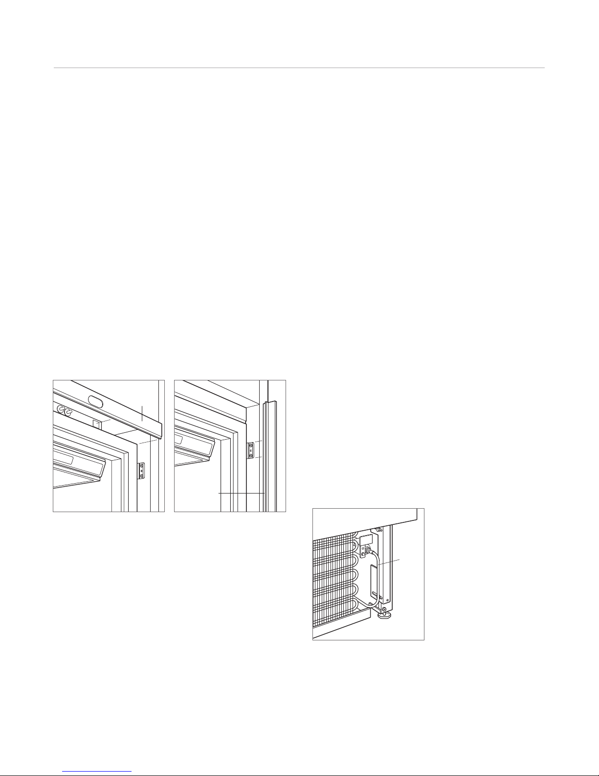
nstall the decorative white molding strips to the top and
I
sides of the integrated unit for a finished look. The top
molding strip, us ed on column and tall models, must be
installed before the side molding can be attached. The top
molding strip is he ld in place by double-sided velcro. The
side molding stri ps snap into place over brackets attached
to the side of the unit . Refer to the illustrations below for
positioning. Fo r installations where units are side by side,
refer to dual installations on page 20.
If you choose, the mo lding strips may be painted to match
surrounding cabinetry. Follow these steps: Rough up the
surface to be paint ed with fine grit sandpaper. Wipe with
alcohol to ensure that the surface is clean and dry. Use an
appliance or indu strial grade, oil base, high gloss enamel
paint.
Water Line Co nnection
QUICK CONNECT WATER VALVE
For units with an ice m aker, the quick connect water valve
and PEX tubing are located on the bottom right side of the
unit.
To connect the ice maker water line, attach the union
fitting to the hous e water supply line. Pull the coiled gray
PEX tubing with red cap and captured nut toward the
house water suppl y line. Remove and discard the red cap.
Then attach the tub ing to the union with the nut. Tighten
all connections. Recoil the excess tubing under the unit.
Refer to the illustration below.
Turn on the water supply and check all fittings for leaks.
Make sure the electrical harness is attached to the
solenoid.
An in-line filter i s required when water conditions have
a high sediment con tent.
The ice maker will no t fill with water immediately. Allow 24
hours for proper ice production. The first container of ice
should be discarded. As with any new connection, there
may be impurities i n the ice from the water supply line.
Top molding. Side molding.
IMPORTANT NOTE: Water lines must not be exposed to
freezing temperatures. Exposure could cause damage to
the unit and home.
Water li ne connection.
Page 14
Integrated Installation 14
MOUNTING
BRACKET
Kickplate/Grille Installation
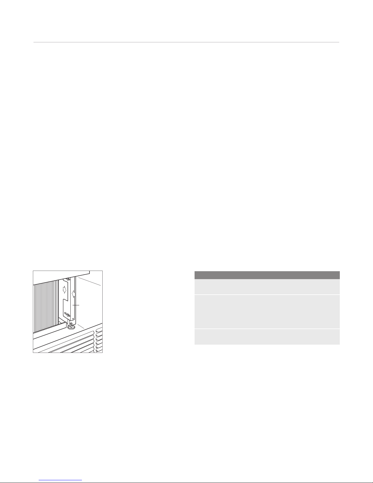
nce the integrated unit is secured, the kickplate/ grille
O
can be installed. T he mounting bracket may be adjusted
slightly forward or back so the kickplate/grille wi ll fit flush
with the surrounding area. Refer to the illustration below.
The kickplate/grille must be removable for service. The
floor cannot inte rfere with removal.
Turn power back on to the electrical outle t.
IMPORTANT NOTE: The unit must be allowed to have
ventilation through the fins of the kickplate/ grille. You may
cover the solid area, but do not block the fins. The lower
drawer panel or the d oor panel of a column unit may hang
in front of the fins, but the baseboard molding must not
cover them.
If you choose, the ki ckplate/grille may be pai nted another
color. Follow these steps: Rough up the surfa ce to be
painted with fine g rit sandpaper. Wipe with alcohol to
ensure that the surface is clean and dry. Use an appliance
or industrial gra de, oil base, high gloss enamel paint.
Panel Considerations
he integrated des ign utilizes custom wood or other
T
decorative pane ls and handles provided by the custo mer.
Stainless steel p anels are available as accessories through
your authorized S ub-Zero dealer. For local dealer information, visit the fin d a showroom section of our website,
subzero.com.
Check panel dimen sions before proceeding. Additional
panel information can be found in the Sub-Zero design
guide and on our webs ite, subzero.com.
IMPORTANT NOTE: A portion of the backside of the
decorative pane ls will need to be finished, as they will be
exposed when the do ors are open.
D-style handles a re recommended. Handl es should be
located on the oppo site side from the hinge, centered on
the cabinet door, and on the top center area of the drawer
panel. Screw heads may have to be countersunk to ensure
that hardware does not interfere with the panel fitting flush.
It is recommended that the door panel of a tall model be
installed first , then the upper and lower drawer panels.
Kickplate /grille installation.
Panel Requirements
COLU MN MODELS MAX WEIG HT
Door Panel 65 lbs (29 kg)
TALL AND DRAWER MODELS MAX WEIG HT
27" (686) Door Panel 40 lbs (18 kg)
27" (686) Drawer Panel 12 lbs (5 kg)
36" (914) Door Panel 53 lbs (24 kg)
36" (914) Drawer Panel 16 lbs (7 kg)
PANEL T HICKNE SS MINIMUM
All Panels
5
/8" (16)
Page 15
Integrated Installation 15
453/8"
(1153)
263/4" (679)
PANELWIDTH
139/16"
(345)
1611/16"
(424)
4" (102)
453/8"
(1153)
353/4" (908)
PANELWIDTH
139/16"
(345)
1611/16"
(424)
27" (686)
FINISHED OPENING
4" (102)
36" (914)
FINISHED OPENING
797/8"
(2029)
797/8"
(2029)
767/8"
(1953)
263/4" (679)
PANELWIDTH
4" (102)
807/8"
(2054)
27" (686)
FINISHED OPENING
1
/8"
(3)
1
/8"
(3)
1
/8"
(3)
1
/8"
(3)
1
/8"
(3)
1
/8"
(3)
1
/8"
(3)
subzero.com/specs
Panel Considerations
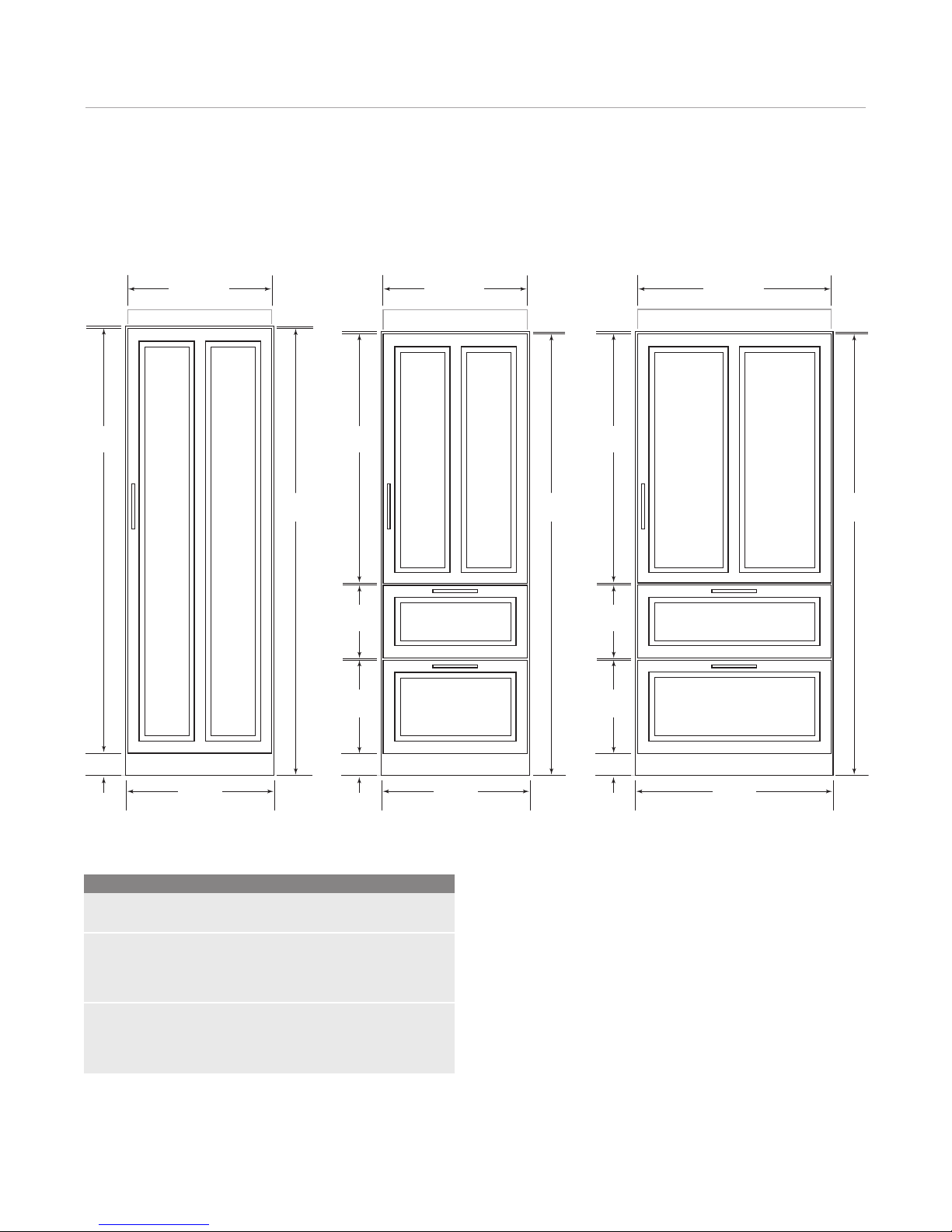
TYPICAL PANEL DIMENSIONS
Typical Panel Dimensions
COLU MN MODELS WH
Door 263/4" (679) 767/8" (1953)
27" (6 86) MODELS WH
Door 263/4" (679) 453/8" (1153)
Top Drawer 263/4" (679) 139/16" (345)
Bottom Drawer 263/4" (679) 1611/16" (424)
36" (9 14) MODELS WH
Door 353/4" (908) 453/8" (1153)
Top Drawer 353/4" (908) 139/16" (345)
Bottom Drawer 353/4" (908) 1611/16" (424)
Panel dimensions are based on a1/8" (3) reveal. A reveal of up
1
/4" (6) is possible with adj ustments to panel dimen sions.
to
Page 16
Integrated Installation 16
INTEGRATED UNIT
(SIDE VIEW)
11/2"
(38)
25" (635) TO WALL
HINGE
DECORATIVE VALANCE
CANNOT EXTEND BEYOND
THE FRONT OF THE MOLDING
DECORATIVE VALANCE
REMOVABLE MOLDING
TYPICAL
HEIGHT
OF DOOR
PANEL
MINIMUM
HEIGHT
OVERALL
HEIGHT
1
/8"(3)
1
/8"(3)
DOOR
PANEL
25" (635) TO WALL
HEIGHT
OF PANEL
I
NTEGRATED UNIT
(SIDE VIEW)
25/8" (67) TO 4" (102)
BASE MOLDING
MUST BE
R
EMOVABLE—
4" (102) MAX
HEIGHT
KICKPLATE /GRILLE
CAN BE ADJUSTED
FORWARD
KICKPLATE /GRILLE
4" (102) TO 9"(229)
FROM FLOOR
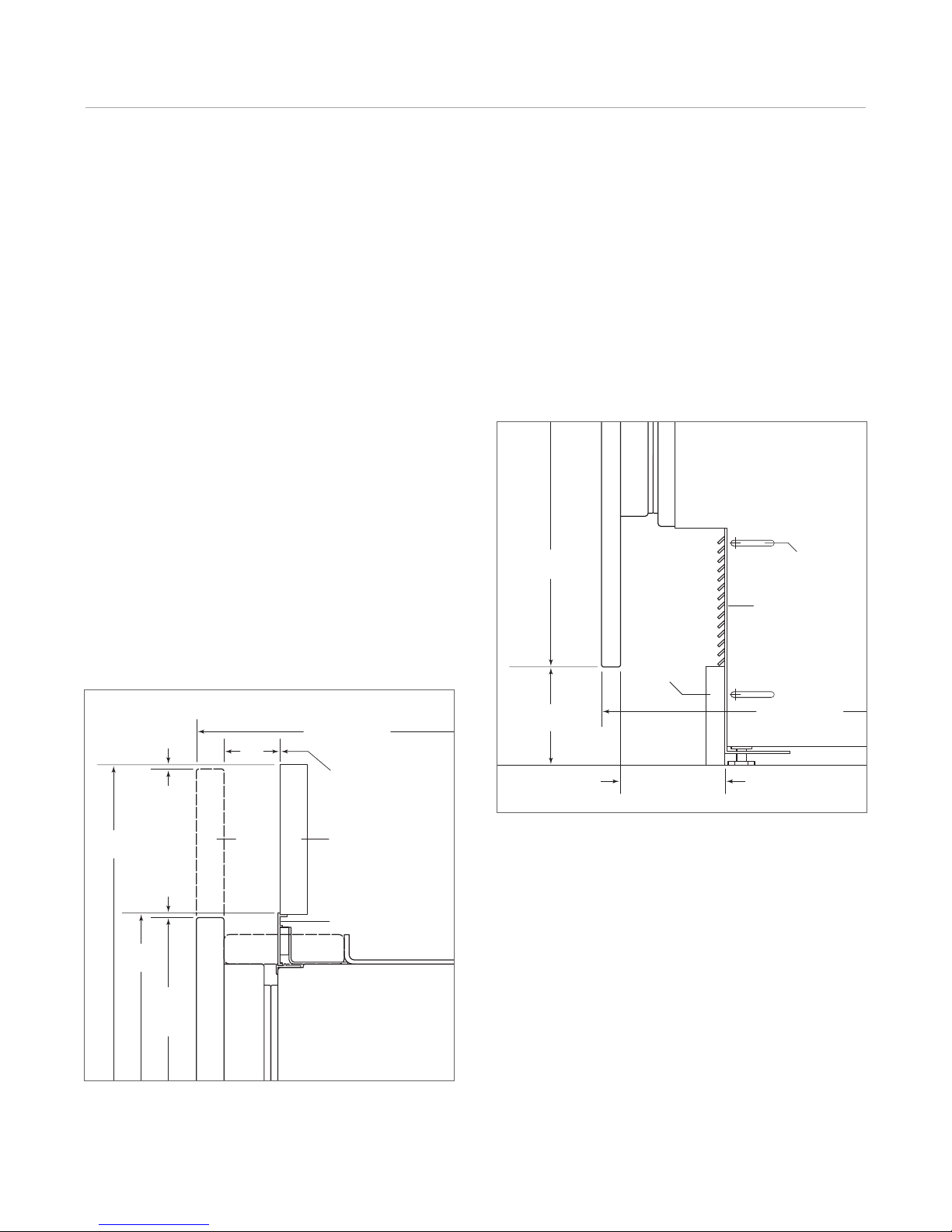
Panel Considerations
DOOR PANEL HEIGHT
The height of the doo r panel can extend beyond the
typical panel hei ght, provided you do not exceed the pa nel
weight limit.
A minimum finished height of 80"
(686) and 36 " (914) tall models. For the 27" (686) integrated
(2032) is required for 27"
column, a minimum finished height of 81" (205 7) is required.
Therefore, when installing a tall model next to a column,
the minimum finis hed height is 81"
(2057). For installations
taller than 80" (2032) or 81" (2057), a d ecorative valance
will be needed to fin ish off the height to the finished surrounding cabinetry.
The illustration below shows how the panel may be
extended and what y ou need to consider to finish the area
behind the door pan el.
IMPORTANT NOTE: The decorative valance used to finish
the area behind the door panel must stay behind the front
plane of the finished molding.
TOE KICK CLEARANCE
The toe kick clearance can vary with the height of the
panel. You must keep a minimum space of 4"
(102) clea r
below the bottom ed ge of the panel for proper venting. In
addition, any dec orative base molding must b e removable
and cannot exceed 4 "
(102) in hei ght.
Upper valence.
Kickplate/grille area.
Page 17
Integrated Installation 17
subzero.com/specs
Panel Installation
DOOR PANEL INSTALLATION
Remove the two piec es of mounting hardware attached to
the front of the door and set aside. Place the door panel
lying face down on a protected surface to ensure that the
front is not scratched or damaged.
Position the plas tic template as indicated on the template.
One side is for a right -hinge unit and the other side is for a
left-hinge unit . Verify that you are using the correct side.
Once you have locat ed the proper position of the
template, mark th e pilot holes indicated on the template.
Remove the template and drill the pilot holes. Next, place
the bottom holes of t he bracket over the pre-drilled ho les
and secure with the #8 x
1
/2" screws provided. After the
bracket has been se cured to the pilot holes, drill the
remaining bracket holes and secure the bracket to the
panel with screws provided.
IMPORTANT NOTE: Dimensions are based on a
1
/8" (3)
reveal. A reveal of up to1/4" (6) is possible. Panel dimensions must be adjus ted accordingly.
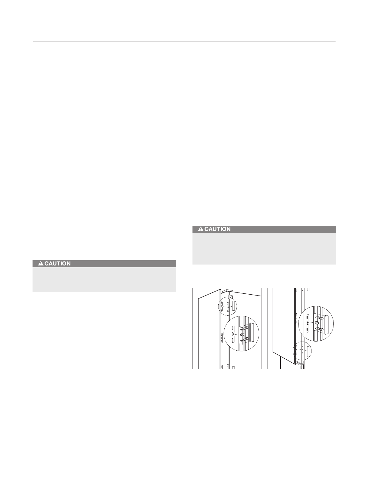
efore attaching the door panel to the door, place a screw
B
in the center of the up per and lower mounting positions,
just enough that th e slotted holes on the hinge si de door
panel bracket wil l slide under the heads. These positioning
screws will support the door panel during installation and
adjustment. Ref er to the illustrations bel ow.
Install the door pa nel by engaging the tabbed bracket to
the handle side of th e door first and then sliding the hinge
side mounting bra cket onto the positioning screws on the
hinge side of the doo r. The pane l can be adjusted
1
/4" (6)
up and down and side to s ide.
Once the door panel i s in place and adjusted correctly,
attach the remaining #10 x
1
/2" screws to the hinge side
mounting bracket and install the magnetic caps as shown
in the illustration below.
As the reveal between cabinets and the unit decreases,
the potential exists for severe finger pinching if fingers
are placed in the opening when the door is closing.
Exercise caution when drilling holes for mounting
hardware. This is especially critical with inset panels.
Mounting position—column. Mounting position—tall model.
Page 18
Integrated Installation 18
53/16" (132)
55/16"
(135)
87/16"
(214)
115/16"
(287)
11/4"
(32)
11/4"
(32)
237/8" (606) FOR 27" UNITS
3
2
7
/8" (835) FOR 36" UNITS
LH DOOR SWING
BACK OF PANEL
RH DOOR SWING
BACK OF PANEL
BACK OF PANEL
BACK OF PANEL
17/16"(37)
811/16"*
(221)
73/16"*
(183)
24" (610)
113/16"(46)
LH DOOR SWING
BACK OF PANEL
RH DOOR SWING
BACK OF PANEL
*Dimensions are based on a 4" (102) toe kick.
Panel Installation
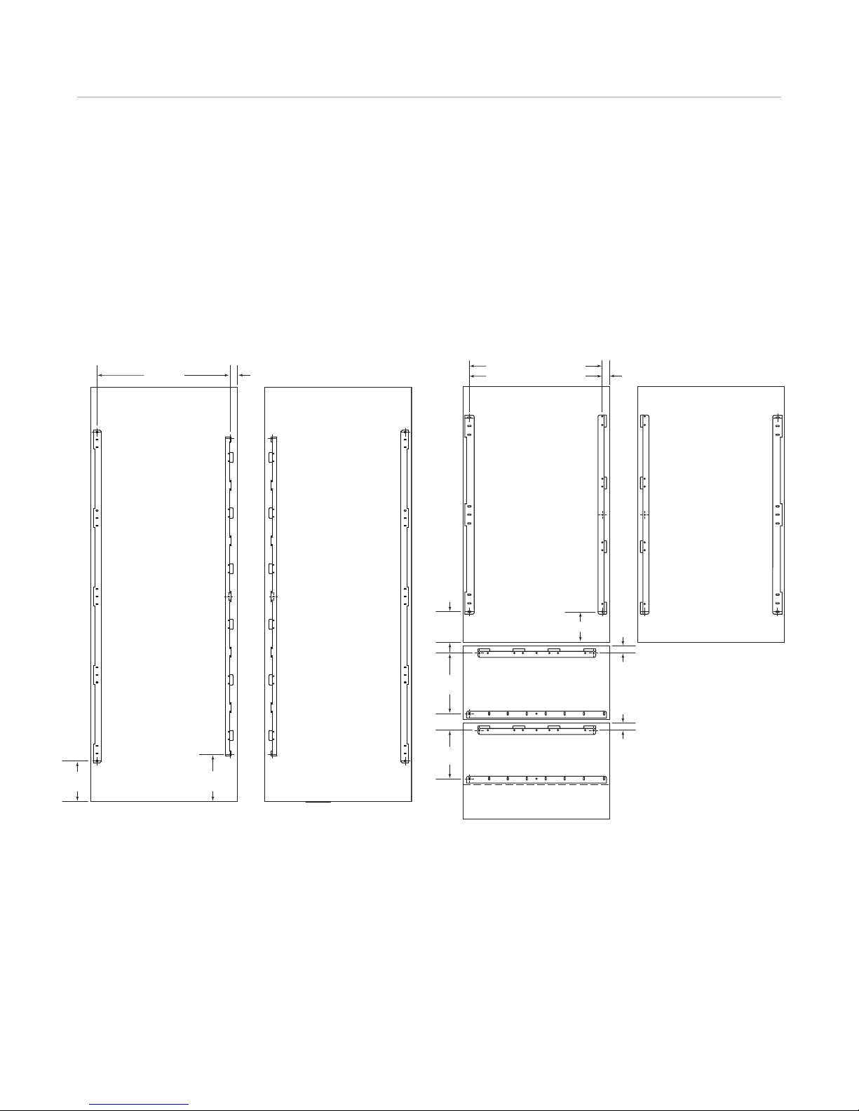
PANEL BRACKET POSITIONING
The illustrations below show placement of panel mounting
brackets. Dimen sions are based on a 4"
1
a
/8" (3) reveal. A reveal of up to1/4" (6) is possible, but
panel dimensions need to be adjusted accordingly.
(102) toe ki ck and
COLUMN MODELS TALL AND DRAWE R MODELS
Page 19
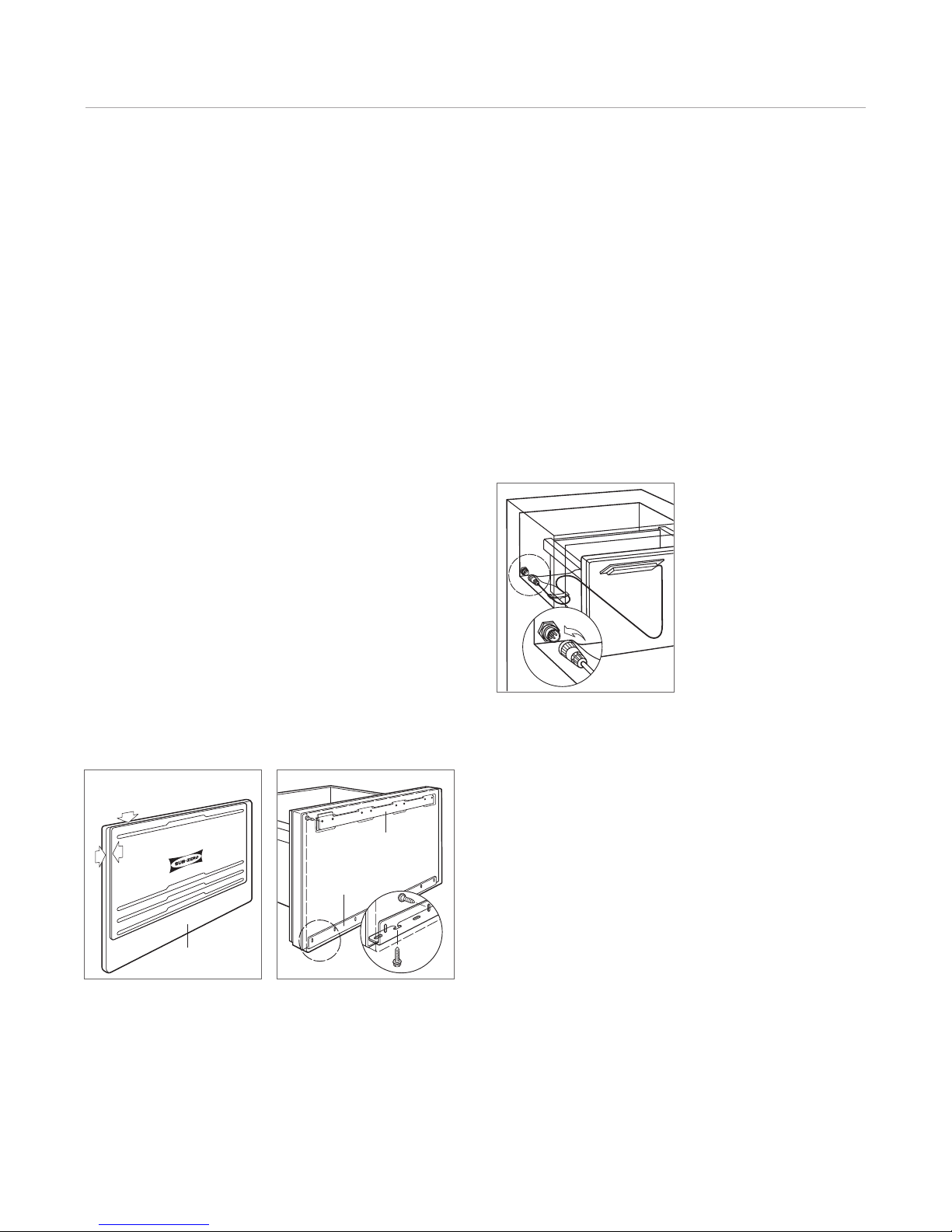
Integrated Installation 19
BACK OF PANEL
TEMPLATE FLUSH WITH
TOP OF PANEL
SIDE
EDGE GAP
WILL VARY
TABBED BRACKET
L BRACKET
subzero.com/specs
Panel Installation
ith the two mounting brackets in place, install the
DRAWER PANEL INSTALLATION
Remove the mounting hardware provided and set aside.
As with the door pane l, you should work on the back side
of each drawer pane l to protect the front surface.
Position the top ed ge of the template flush with the top
edge of each drawer. For the top drawer, there is onl y one
location for the lo wer mounting bracket. The bottom
drawer allows a sec ond option by inverting the lower
mounting bracket, depending on the height and thickness
of the panel. Refer t o the illustration below.
Secure the template in place and mark the pilot holes.
Remove the template and drill pilot holes for mounting the
bracket. Place th e mounting brackets in the proper
location with the t abbed bracket on top and L-bracket on
the bottom of the pan el. Fasten brackets securely wit h the
1
#8 x
/2" screws provided. Refer to the illustration below.
W
drawer panel by eng aging the top tabbed bracket first,
then slide the lowe r L-bracket onto the positioning screws.
Each drawer panel c an be adjusted
1
/4" (6) up and down
and side to side. Fas ten all screws to the lower L-bracket
to secure the drawer panel.
The drawers can be pl aced back in the unit. Reconnect
the control cable for the top drawer (drawer models only).
Refer to the illustration below.
To help with the placement of the drawer panels, exam ine
the lower L-bracket and panel to determine the slotted
holes on the bracket that will be used. Then position
screws into the lower portion of the drawer that correspond with these sl ots. Leave the screws out slightly s o
the slotted holes w ill slide under the heads.
Templat e position. Drawer panel installation.
Control cable.
Page 20
Integrated Installation 20
Dual Installations
wo integrated uni ts may be placed side by side in a dual
T
installation. P anel width dimensions will vary slightly from
single installations. A dual installation kit is required for
installations w ith 2"
Dual installation kits are available through your autho rized
Sub-Zero dealer.
IMPORTANT NOTE: If a 27" (686) unit is installed next to a
36"
(914) tall m odel, the decorative front panel s will align,
(51) or less space between un its.
90° Door Stop
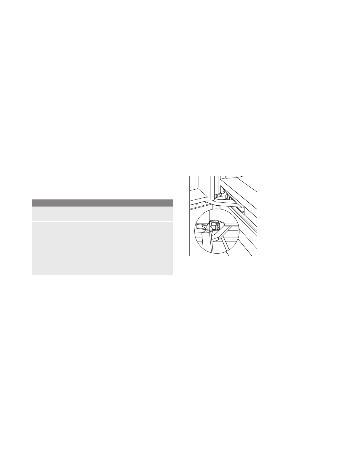
he door of integrated columns and tall models opens
T
to 105°. A 90° door sto p is built into the hinge system for
installations w here the door opening must be limited.
To engage the door stop, use the blade edge of a
standard screwdriver and rotate the cam in the center
portion of the hing e. You must make this adjustment to
both the bottom and t op hinge. Refer to the illustration
below.
however, the face frames will not. This is only a pparent
when both doors are open at the same time. Due to a
more robust hinge on 36"
(914) unit s, the face frame was
reconfigured to maintain a consistent overall panel hei ght.
Typical Panel Dimensions
COLU MN MODELS WH
Door 2613/16" (681) 767/8" (1953)
686)
27" (
MODE LS WH
Door 2613/16" (681) 453/8" (1153)
Top Drawer 2613/16" (681) 139/16" (345)
Bottom Drawer 2613/16" (681) 1611/16" (424)
36" (9 14) MODELS WH
Door 3513/16" (910) 453/8" (1153)
Top Drawer 3513/16" (910) 139/16" (345)
Bottom Drawer 3513/16" (910) 1611/16" (424)
90° door stop.
Page 21

Integrated Installation 21
subzero.com/specs
Installation Checklist
o ensure a safe and proper installation, the following
T
checklist shoul d be completed by the installer to ensure
that no part of the ins tallation has been overlooked.
INSTALLATION CHECKLIST
Have all packing ma terials been removed?
Turn the unit on. Is it operating properly?
Is the power cord plugged into a properly grounded
outlet, which has b een installed in accordance with all
applicable elec trical codes?
For units with an aut omatic ice maker, is the water
supply line conne cted and not leaking? Is the water
supply turned on and ice maker control on?
Has the anti-tip br acket been installed securely an d
properly engaging the unit?
Is the unit leveled p roperly with all leveling legs mak ing
contact with the fl oor? Has the kickplate/grille been
installed?
Are panels attached securely and properly align ed?
Has the door been ali gned for proper appearance and
operation?
Does the customer u nderstand the unit's oper ation?
Does the customer h ave the warranty package?
Have any installation or service problems been noted
on the product registration card? Has the registration
card been mailed in?
Have stainless st eel panels been inspected for any
imperfections? This is to be done by the authorized
Sub-Zero dealer or installer with the customer, upon
completion of ins tallation. Stainless steel panels are
covered by a limited 60-day warranty for cosmetic
defects.
Page 22
Service Information 22
Service Information
f service is necessary, maintain the quality built in to your
I
integrated unit b y calling Sub-Zero factory certified
service.
For the name and numb er of Sub-Zero factory certified
service nearest you, check the contact & support section
of our website, sub zero.com or call Sub-Zero customer
care at 800-222-7820.
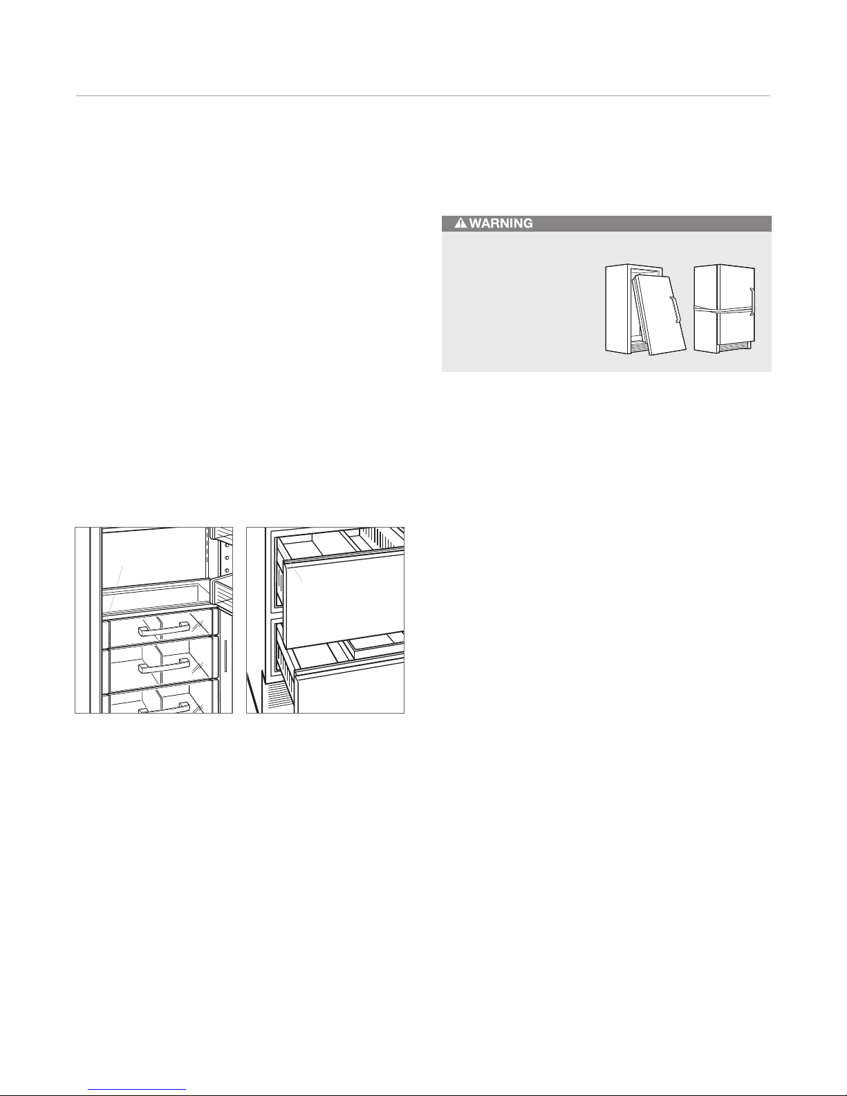
When calling for se rvice, you will need the model and
serial numbers of y our unit. Both numbers are listed on t he
product rating plate. For column models, the rating plate
is located inside t he top drawer near the drawer guide
opposite the hing e. For tall and drawer models, the rating
plate is located in side the cabinet, to the left of the upper
drawer. Refer to the illustrations below.
If you are storing or disposing of your old refrigerator or
freezer, please do it
safely. Remove the
doors or tightly secure
the doors closed.
Child entrapment
accidents can be tragic.
RATING PLATE
RATING PLATE
Tall and drawer mode ls.Column models.
Page 23

The information and images in this guide are the copyright property of Sub-Zero, Inc. Neither this guide nor any information or images contained herein may be
copied or used in whole or in part without the express written permission of Sub-Zero, Inc. ©Sub-Zero, Inc. all rights reserved.
Wolf, Wolf & Design, Wolf Gourmet, W & Design and the color red as applied to knobs are registered trademarks and service marks of Wolf Applian ce, Inc.
Sub-Zero, Sub-Zero & Design, Dual Refrigeration, Constant Care and The Living Kitchen are registered trademarks and servi ce marks of Sub-Zero, Inc.
(collectively,the“Company Marks.”) All other trademarks or registered trademarks are property of their respective owners in the United States and other countries.
Page 24
SU B-ZER O, IN C. P. O . BOX 4 4848 MA DISON , W I 5374 4 SUBZE RO.CO M 800 .222. 7820
702 3602 REV-A 12 /2011
 Loading...