

Page 1
IInntteeggrraatteedd
IInntteeggrraatteedd
((770000--
((770000--
33
33
TTAALLLL))
TTAALLLL))
SSeerriieess
SSeerriieess
© SUB-ZERO FREEZER COMPANY INC. 2006 ALL RIGHTS RESERVED JOB AID #3758412 (Revision B - December 2006)
TTeecchhnniiccaall
SSeerrvviiccee MMaannuuaall
Page 2

Page 3

Integrated
Integrated
(700-
(700-
3
3
TTALL)
ALL)
Series
Series
General Information
1-1
#3758412 - Revision B - December, 2006
SECTION 1
GENERAL
INFORMATION
Page 4
General Information
Integrated
Integrated
(700-
(700-
3
3
TTALL)
ALL)
Series
Series
1-2
#3758412 - Revision B - December, 2006
TECHNICAL ASSISTANCE
If you should have any questions regarding the
700-3 Series and/or this manual, please contact:
Sub-Zero Freezer Company, Inc.
ATTN: Service Department
P.O. Box 44988
Madison, WI 53744 - 4988
Customer Service & Parts / Warranty Claims
Phone #: (800) 222 - 7820
Technical Assistance
Phone #: (800) 919 - 8324
Customer Service & Technical Assistance
Facsimile #: (608) 441 - 5887
Parts / Warranty Claims
Facsimile #: (608) 441 - 5886
Service Department E-Mail Address:
customerservice@subzero.com
Office Hours:
7:00 AM to 7:00 PM Central Time
Monday through Friday
IMPORTANT SAFETY INFORMATION
Below are Product Safety Labels used in this manual.
The "Signal Words" used are WARNING or CAUTION.
When reviewing this manual, please note these different Product Safety Labels placed at the beginning of
certain sections of this manual. You must follow the
instructions given in the boxes of the Product Safety
Labels in order to avoid personal injury and/or product
damage.
The sample Product Safety Labels below illustrate the
precautions that should be taken when the signal word
is observed.
INTRODUCTION
This Technical Service Manual has been compiled to provide the most recent service information for 700-3 Series
Tall units. This information will enable the service technician to troubleshoot and diagnose malfunctions, perform
necessary repairs, and return a unit to proper operational condition.
The service technician should read the complete instructions contained in this manual before initiating any repairs on
a 700-3 Tall Series unit.
INDICATES THAT HAZARDOUS OR UNSAFE PRACTICES COULD RESULT IN SEVERE PERSONAL
INJURY OR DEATH.
Indicates that hazardous or unsafe practices could
result in minor personal injury, and/or product damage, and/or property damage.
In addition, please pay attention to the signal word
“NOTE”, which highlights information that is espe-
cially important for the topic being covered.
This manual is designed to be used by Authorized Service Personnel only. Sub-Zero Freezer Co., Inc.
assumes no responsibility for any repairs made on Sub-Zero refrigeration units by anyone other than
Authorized Service Technicians.
Information and images contained in this manual are the copyright property of Sub-Zero Freezer Company, Inc.
Neither this manual nor any information or images contained herein may be copied or used in whole or in part
without the express written consent of Sub-Zero Freezer Company, Inc.
© Sub-Zero Freezer Company, Inc, all rights reserved.
Page 5
Integrated
Integrated
(700-
(700-
3
3
TTALL)
ALL)
Series
Series
General Information
1-3
#3758412 - Revision B - December, 2006
Section 1 - General Information 1-1
Introduction ....................................................................... 1-2
Important Safety Information ............................................ 1-2
Technical Assistance ........................................................ 1-2
Table of Contents ............................................................. 1-3
Warranty Information ........................................................ 1-5
Model Description ............................................................. 1-6
Section 2 - Installation Information 2-1
Installation Considerations ............................................... 2-2
Unit leveling ................................................................. 2-2
Door & Drawer Adjustment ........................................... 2-3
Door Stop Adjustment .................................................. 2-3
Dual Unit Installation .................................................... 2-4
Section 3 - Electronic Control System Information 3-1
Terminology & Component Descriptions .......................... 3-2
Basic Electronic Control System ....................................... 3-3
Control Board Layout & Summary Table ......................... 3-4
Control Panel Layout ....................................................... 3-5
Basic Electronic Control Input Operations ....................... 3-5
Unit ON/OFF ................................................................ 3-5
Adjusting Set-Point (Temp. Adjustment) ...................... 3-6
Icemaker System ON/OFF ........................................... 3-6
Door Ajar Alarm Feature ON/OFF ................................ 3-6
Unique Electronic Control Input Operations .................... 3-7
Temperature Units Selection Mode .............................. 3-7
Sabbath Mode .............................................................. 3-8
Showroom Mode .......................................................... 3-8
Manual Zone Disable Mode .......................................... 3-9
Manual Freezer Evaporator Defrost ............................. 3-9
Functions of the Electronic Control System ................... 3-10
Supply Power to the Lighting System ........................ 3-10
Monitor, Regulate & Display Compartment Temp’s ..... 3-11
Control Variable Speed Compressor (700TF/I-3) ........ 3-12
Control Condenser Fan Run ....................................... 3-13
Refrigerator “Fan-Assisted Off-Cycle Defrost” ............. 3-14
Freezer “Adaptive Defrost” .......................................... 3-15
Monitor Compressor Run, Display Service ................. 3-16
Monitor Speed Signal to Variable Speed Comp.,
Display Service (700TF/I-3) ......................................... 3-17
Monitor Ice Making System, Display Service .............. 3-18
Possible Error Indicators ................................................ 3-19
700TC/I-3 & 736TC/I-3 ................................................. 3-19
700TR-3 & 736TR-3 .................................................... 3-20
700TF/I-3 ..................................................................... 3-21
Troubleshooting Input Operations ................................... 3-22
Diagnostic Mode ........................................................ 3-22
Thermistor Location Code Tables ........................... 3-23
Diagnostic Mode Indicators ...................................... 3-23
Error Code Table ...................................................... 3-24
Clearing Error Codes ................................................ 3-24
Manual Component Activation Mode ........................... 3-25
Temperature Log Recall Mode ................................... 3-26
Compartment Temp. History Only ............................ 3-26
Compartment & Evaporator Temp. History .............. 3-27
Possible Event Indicators ..................................... 3-28
Temperature Log Index Chart ................................ 3-29
Section 4 - Sealed System Information 4-1
HFC-134a Refrigerant Service Information ...................... 4-2
General Rules for Working with 134a Refrigerant ........ 4-2
Sealed System Repair Procedures .............................. 4-3
Sealed System Operation ................................................ 4-4
Sealed System Refrigerant Flow Diagrams ..................... 4-6
Models 700TC/I-3 & 736TC/I-3 ...................................... 4-6
Models 700TR-3 & 736TR-3 .......................................... 4-7
Model 700TF/I-3 ............................................................ 4-7
Section 5 - Air Flow & Fan Blade Spacing 5-1
Models 700TC/I-3 & 736TC/I-3 .......................................... 5-2
Models 700TR-3 & 736TR-3 .............................................. 5-3
Model 700TF/I-3 ................................................................ 5-3
Section 6 - Icemaker Information
6-1
Modular Icemaker ........................................................... 6-2
Modular Icemaker Operation ...................................... 6-2
Additional Icemaker Operation Notes ......................... 6-3
What Happens During Ejector Blade Rotation ............ 6-3
Modular Icemaker Test Procedures ................................ 6-4
Voltage Tests ................................................................ 6-4
Continuity Tests & Thermostat Inspection ................... 6-4
Water Fill Adjustment ...................................................... 6-5
Icemaker Disassembly .................................................... 6-5
Module/Motor Assembly ............................................. 6-5
Mold/Heater Assembly ............................................... 6-5
Ejector Blades and/or Ice Stripper .............................. 6-5
Icemaker Thermostat ................................................. 6-5
Section 7 - Component Access and Removal 7-1
Component Access and Removal ............................ 7-2
WARNINGS & CAUTIONS ................................................ 7-2
Exterior Cosmetic and Mechanical Components ......... 7-3
Kickplate/Grille .............................................................. 7-3
Side Molding Strip .......................................................... 7-3
Upper Compartment Light Switch and Fan Switch ........ 7-3
Drawer Assembly .......................................................... 7-4
Door & Drawer Gasket ................................................. 7-4
Door Assembly ............................................................. 7-5
Upper and Lower Hinge Assembly ................................ 7-5
TABLE OF CONTENTS
Page #
Page #
Page 6
General Information
Integrated
Integrated
(700-
(700-
3
3
TTALL)
ALL)
Series
Series
1-4
#3758412 - Revision B - December, 2006
Interior Cosmetic, Mechanical and Electrical
Components ................................................................... 7-6
Door Shelf and Dairy Compartment ............................ 7-6
Compartment Shelf ....................................................... 7-6
Upper Light Diffuser ...................................................... 7-7
Light Bulb...................................................................... 7-7
Control Board ................................................................ 7-8
Control Panel Assembly ................................................ 7-8
Upper Evaporator Cover / Air Duct ............................... 7-9
Upper Evaporator Fan Shroud Assy ............................. 7-9
Upper Compartment Evaporator Fan Assy .................. 7-10
Upper Compartment Thermistor ...................................7-10
Upper Evap. Thermistor (All Except 700TF/I-3) .......... 7-10
Drawer Closer Assembly .............................................. 7-11
Drawer Slide Assembly ................................................ 7-11
Drawer Slide Pin ....................................................... 7-11
Icemaker Assy. (All Models w/Icemaker) .................... 7-11
Heat Exchanger Cover ................................................ 7-12
Lower Evap. Cover Assy (700TR-3, 736TR-3) ........... 7-12
Lower Evap. Fan Assy (700TR-3, 736TR-3) .............. 7-12
Lwr Cmprtmnt Thermistor (700TR-3, 736TR-3) ........... 7-13
Lwr Evap. Thermistor (700TR-3, 736TR-3) ................. 7-13
Lower Evaporator Cover Assy
(700TC/I-3, 700TF/I-3, 736TC/I-3) ............................... 7-13
Drain Trough Heater
(700TC/I-3, 700TF/I-3, 736TC/I-3) ............................... 7-14
Lower Evaporator Fan Shroud
(700TC/I-3, 700TF/I-3, 736TC/I-3) ............................... 7-14
Lower Evaporator Fan Assy
(700TC/I-3, 700TF/I-3, 736TC/I-3) ............................... 7-14
Defrost Terminator
(700TC/I-3, 700TF/I-3, 736TC/I-3) ............................... 7-15
Defrost Heater (700TC/I-3, 700TF/I-3, 736TC/I-3) ...... 7-15
Switch Enclosure Assembly ......................................... 7-16
Lower Evaporator Thermistor
(700TC/I-3, 700TF/I-3, 736TC/I-3) ............................... 7-16
Lower Compartment Thermistor
(700TC/I-3, 700TF/I-3, 736TC/I-3) ............................... 7-17
Fill Tube Heater (700TC/I-3, 700TF/I-3, 736TC/I-3) .... 7-17
Lower Compartment Light / Fan / Icemaker Switch ..... 7-17
Compressor Area Electrical & Mechanical
Components ................................................................... 7-18
IM Water Valve (700TC/I-3, 700TF/I-3, 736TC/I-3) ..... 7-18
Condenser Fan Assembly ........................................... 7-19
Sealed System Components ....................................... 7-20
Upper Compartment Evap (All Except 700TF/I-3) ...... 7-20
Lower Compartment Evaporator ................................ 7-20
High-Side Filter-Drier ................................................... 7-21
Compressor ................................................................. 7-22
Condenser .................................................................... 7-23
Upper Compartment Heat Exchanger ......................... 7-24
Lower Compartment Heat Exchanger ......................... 7-25
Page #
Page #
Section 8 - Troubleshooting Guides 8-1
How to Use Error Code Troubleshooting Guide ............... 8-2
Error Code Table ............................................................ 8-2
Error Code Troubleshooting Guide ................................ 8-3
How to Use the General Troubleshooting Guide ............. 8-5
General TS Guide Table of Contents ............................. 8-6
Sealed System Troubleshooting / Diagnostic Tables .... 8-20
Normal Operating Pressures ....................................... 8-20
Pressure Indications ................................................... 8-21
Temperature/Low Side Pressure.................................. 8-21
Membrane Switch / Ribbon Cable Test .......................... 8-22
Door Hinge Operation Test & Corrections ..................... 8-23
Section 9 - Technical Data Tables 9-1
Model 700TC/I-3 .............................................................. 9-2
Model 700TR-3 ............................................................... 9-3
Model 700TF/I-3 .............................................................. 9-4
Model 736TC/I-3 .............................................................. 9-5
Model 736TR-3 .............................................................. 9-6
Section 10 - W
iring Diagrams 10-1
700TC/I-3 Wiring Diagram .............................................. 10-2
700TC/I-3 Wiring Schematic ........................................ 10-3
700TR-3 Wiring Diagram ................................................ 10-4
700TR-3 Wiring Schematic .......................................... 10-5
700TR-3 Wiring Diagram ................................................. 10-6
700TR-3 Wiring Schematic ......................................... 10-7
700TF/I-3 Wiring Diagram ............................................. 10-8
700TF/I-3 Wiring Schematic ...................................... 10-9
736TC/I-3 Wiring Diagram ............................................ 10-10
736TC/I-3 Wiring Schematic ...................................... 10-11
736TR-3 Wiring Diagram ............................................... 10-12
736TR-3 Wiring Schematic ........................................ 10-13
Page 7
Integrated
Integrated
(700-
(700-
3
3
TTALL)
ALL)
Series
Series
General Information
1-5
#3758412 - Revision B - December, 2006
736TCI 3 0000000
7.0
9.0 8.1 R134a
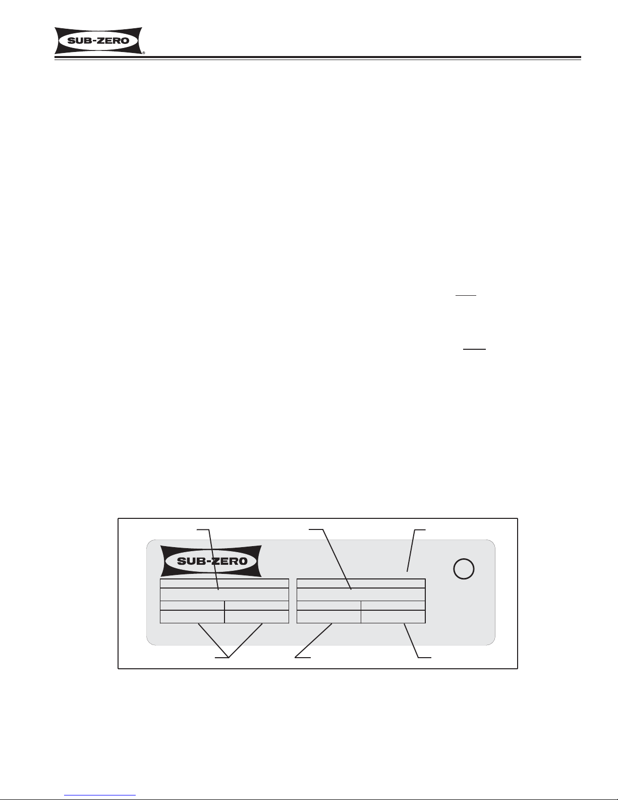
Figure 1-1. Serial Tag Layout
(The serial number tag is located on the left side wall of the upper drawer compartment.)
Jul 2005
Model Number
Serial Number
Manufacture Date
Refrigerant Charge
Total Amps Refrigerant Type
WARRANTY INFORMATION
This page summarizes the 2, 5 & 12 Year Residential
Warranty provided with every Sub-Zero, as well as two
special warranties:
• Non-Residential Warranty - Applies to units installed
in non-residential applications.
• Display/Model Home Warranty - Applies to distribu-
tor or dealer display units, and units in model
homes, sold three years after date of manufacture.
Following the warranty summaries are details and notes
about the warranties.
TWO, FIVE & TWELVE YEAR Warranty
• 2 year TOTAL PRODUCT, *parts and labor.
• 5 Year SEALED SYSTEM, **parts and labor.
• 6th - 12th year LIMITED SEALED SYSTEM, **parts
only.
ONE & FIVE YEAR Non-Residential Warranty
(Example: Office, Yacht, etc.)
• 1 Year TOTAL PRODUCT, *parts and labor.
• 5 Year SEALED SYSTEM, **parts and labor.
ONE & FIVE YEAR Display/Model Home Warranty
(Display units sold three years after date of manufacture)
• 1 Year TOTAL PRODUCT, *parts and labor.
• 5 Year SEALED SYSTEM, **parts and labor.
Warranty Details:
* Includes, but is not limited to the following:
Electronic Control System Components, Fan & Light
Switches, Fan Motors & Blades, Defrost & Drain
Heaters, Defrost Terminator, Drain Pan, Drain Tubes,
Wiring, Light sockets & bulbs, Icemaker, Water Valve,
Door hinges, Door closers & Cams, Compressor
Electricals, etc. . .
* Stainless Steel (Classic, Platinum & Carbon) doors,
panels and product frames are covered by a limited 60
day parts and labor warranty for cosmetic defects.
** Includes the following:
Compressors, Condenser, Evaporators, Filter-Driers,
Heat-exchangers, All Tubing that Carries the Freon.
NOTE: Condenser Fan Motors, Freon, Solder and
compressor electricals are NOT
considered sealed
system parts.
Warranty Notes:
• All warranties begin at unit's initial installation date.
• All Warranty and Service information collected by SubZero is arranged and stored under the unit serial number, and the customer's last name.
Sub-Zero requests that you have the model and serial
number available whenever contacting the factory or
parts distributor.
• The serial tag is located on the left wall of the upper
drawer compartment.
REFRIGERATOR
PRODUCT SERVICE 1-800-222-7820
MODEL
MADISON, WI
REFRIGERANT
FREEZER
FREEZER CO., INC.
SERIAL NUMBER
TOTAL AMPS
115Vac, 60Hz, 1 Phase
LISTED HOUSEHOLD
REFRIGERATOR OR FREEZER
U
R
O
L
CUS
LISTED
776N
Date Code
ALSO VERIFIED IN
ACCORDANCE WITH
ENERGY STANDARD
CAN/CSA-C300-91
Page 8
General Information
Integrated
Integrated
(700-
(700-
3
3
TTALL)
ALL)
Series
Series
1-6
#3758412 - Revision B - December, 2006
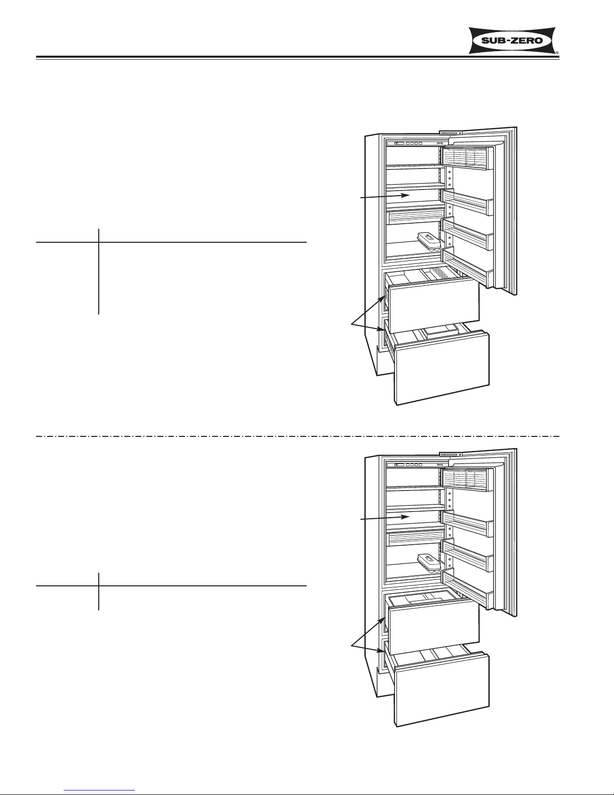
Figure 1-2. Model 700TC-3 & 700TCI-3
Lower Two
Drawer
Freezer
Zone
MODEL DESCRIPTIONS
This page briefly describes the models covered in this 700-3 Tall Unit Technical Service Manual.
Upper
Refrigerator
Zone
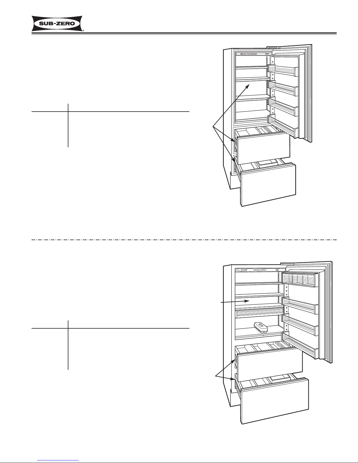
Figure 1-3. Model 700TR-3
Lower Two
Drawer
Refrigerator
Zone
Upper
Refrigerator
Zone
700TC-3
700TCI-3
MODEL DESCRIPTION
700 Series, 27
” Wide
Tall Combination
Refrigerator/Freezer
, 3rd Design Build
7
00 Series, 27” Wide
Tall Combination
Refrigerator/Freezer
, w/Icemaker, 3rd Design
Build
700TR-3
MODEL DESCRIPTION
700 Series, 27” Wide Tall Refrigerator, 3rd
Design Build
Page 9
Integrated
Integrated
(700-
(700-
3
3
TTALL)
ALL)
Series
Series
General Information
1-7
#3758412 - Revision B - December, 2006
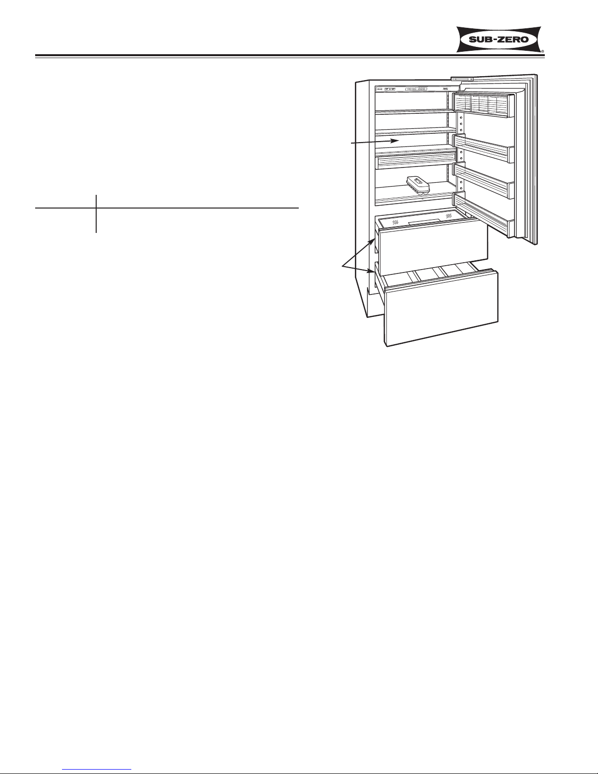
Figure 1-4. Model 700TF-3 & 700TFI-3
All
Freezer
Zone
700TF-3
700TFI-3
MODEL DESCRIPTION
700 Series, 27
” Wide
Tall Freezer, 3rd Design
Build, Variable Speed Compressor
700 Series, 27” Wide Tall Freezer, w/Icemaker,
3rd Design Build, Variable Speed Compressor
Figure 1-5. Model 736TC-3 & 736TCI-3
Lower Two
Drawer
Freezer
Zone
Upper
Refrigerator
Zone
736TC-3
736TCI-3
MODEL DESCRIPTION
700 Series, 36” Wide Tall Combination
Refrigerator/Freezer,
3rd Design Build
700 Series, 36” Wide Tall Combination
Refrigerator/Freezer
, w/
Icemaker, 3rd Design
Build
Page 10
General Information
Integrated
Integrated
(700-
(700-
3
3
TTALL)
ALL)
Series
Series
1-8
#3758412 - Revision B - December, 2006
Figure 1-6. Model 736TR-3
Lower Two
Drawer
Refrigerator
Zone
Upper
Refrigerator
Zone
736TR-3
MODEL DESCRIPTION
700 Series, 36” Wide Tall Refrigerator, 3rd
Design Build
Page 11
Integrated
Integrated
(700-
(700-
3
3
TTALL)
ALL)
Series
Series
Installation Information
2-1
#3758412 - Revision B - December, 2006
SECTION 2
INSTALLATION
INFORMATION
Page 12
Installation Information
Integrated
Integrated
(700-
(700-
3
3
TTALL)
ALL)
Series
Series
2-2
#3758412 - Revision B - December, 2006
UNIT COULD TIP FORWARD UNDER CERTAIN LOAD CONDITIONS. FAILURE TO INSTALL ANTI-TIP COMPONENTS AND EXTEND LEVELERS TO THE FLOOR ACCORDING TO INSTALLATION MANUAL COULD
RESULT IN SERIOUS PERSONAL INJURY OR DEATH.
INSTALLATION CONSIDERATIONS
This section covers some of the more common installation issues seen by a service technician. An improper installation, though not a valid service issue, has the potential to lead to a customer placing a call for service. Installation
related customer complaints could include, but are not limited to: Unit leveling, unit movement, door misalignment,
doors and drawers not sealing, internal frost or condensation, warm compartment temperatures, exterior condensation, etc.. .
NOTE: If additional installation information is needed, refer to the complete Installation Manual and/or installation
video, or contact the Sub-Zero Technical Assistance Department.
Unit Leveling
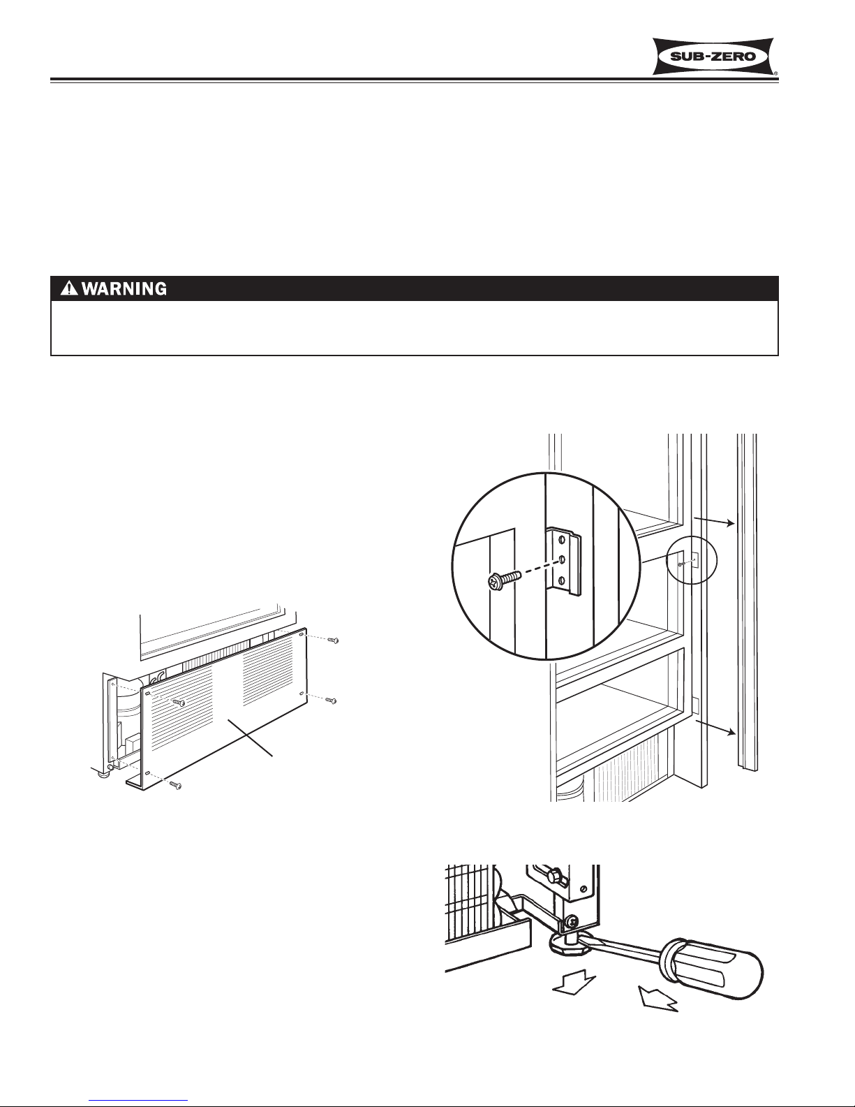
NOTE: The kickplate/grille must be removed before
leveling (See Figure 2-1). If the unit has already been
anchored to the cabinets, the side molding strips must
be removed and the anchor screws must be extracted
from the unit to cabinet brackets before leveling (See
Figure 2-2). These components must be reinstalled
after leveling.
Figure 2-2. Side Molding & Bracket
Figure 2-1. Kickplate/Grille Removal
Figure 2-3. Adjusting Front Levelers
To level the unit, turn the front leveling legs counterclockwise to raise the front or clockwise to lower it. To
assist in turning the front leveling legs up or down, use
a standard straight-blade screwdriver and place it in the
foot of the front leg, then rotate the leveler foot in the
desired direction (See Figure 2-3).
Kickplate / Grille
Page 13
Integrated
Integrated
(700-
(700-
3
3
TTALL)
ALL)
Series
Series
Installation Information
2-3
#3758412 - Revision B - December, 2006
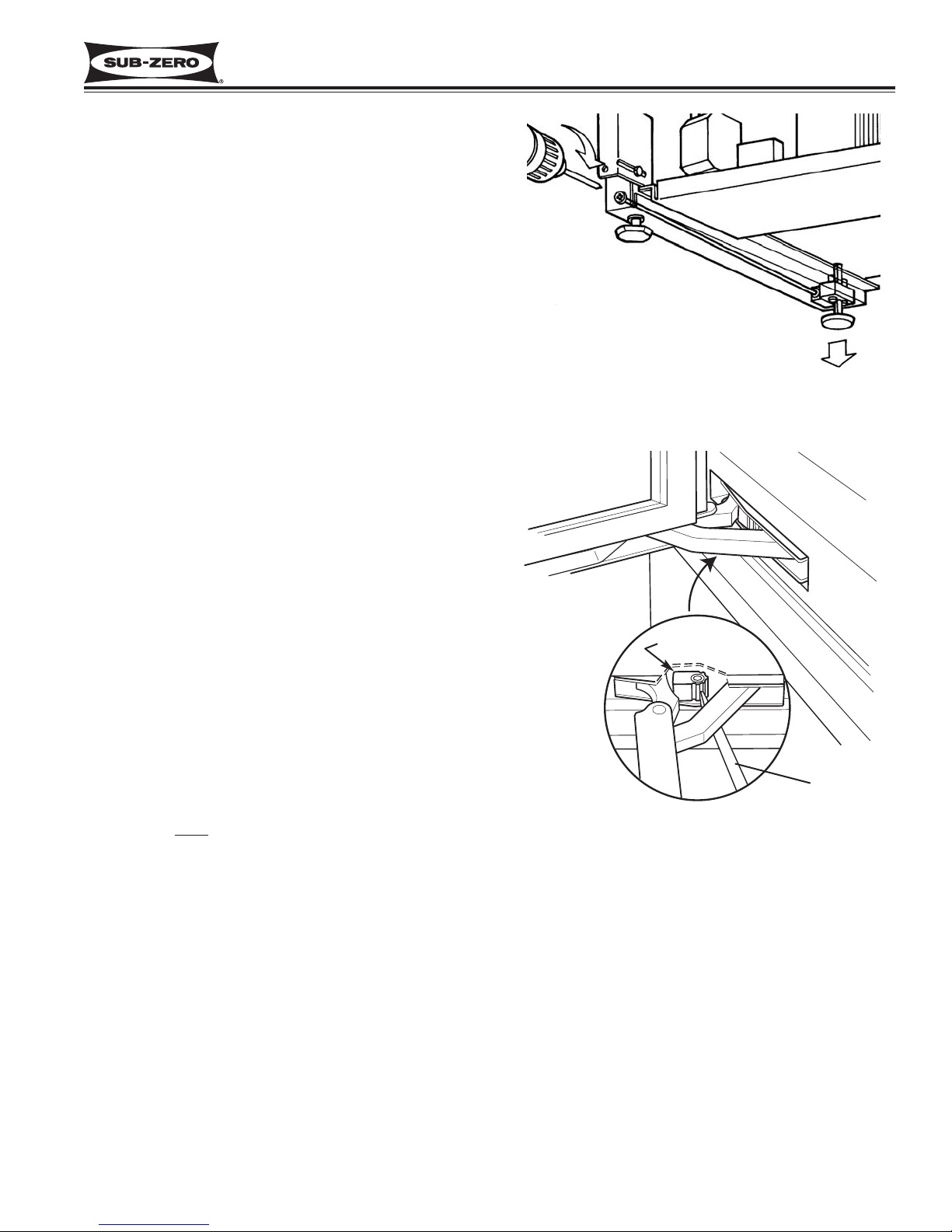
Figure 2-4. Adjusting Rear Levelers
Figure 2-5. 90° Door Stop Cam
Screwdriver
The rear levelers are adjusted from the front of the
base by turning the Phillips head adjusting screw. The
long adjusting screw reaches all the way to the rear leveler assembly. Turn the screw clockwise to raise the
rear or counterclockwise to lower it (See Figure 2-4).
NOTE: The rear leveling legs will only move 1/16” for
every 18 revolutions of the Phillips head screw. Do not
over torque. Use the lowest torque setting on any
power screwdriver. Do not turn rear leveling legs by
hand, doing so will damage the assembly.
Door and Drawer Adjustment
The doors and drawers on 700-2 Series units are nonadjustable. Instead, the door and/or drawer panels
must be adjusted if there is an alignment problem.
Refer to the Installation Manual and/or installation video
for panel installation and adjustment.
NOTE: The unit must be level before attempting to
adjust the door and drawer panels.
NOTE: If the door has problems closing, see Tall Unit
Door Hinge Operation Test Procedures and Corrections
at the end of the Troubleshooting Guide.
Door Stop Adjustment
700-2 Series tall units have a 90° door stop cam built
into the hinge system. The 90° door stop cam is located in the center portion of each hinge. To adjust it, use
a standard straight-blade screwdriver to rotate the cam
until it reaches the stop point (See Figure 2-5).
NOTE: You must
make this adjustment at both bottom
and top hinge.
90° Stop Cam
Page 14
Installation Information
Integrated
Integrated
(700-
(700-
3
3
TTALL)
ALL)
Series
Series
2-4
#3758412 - Revision B - December, 2006
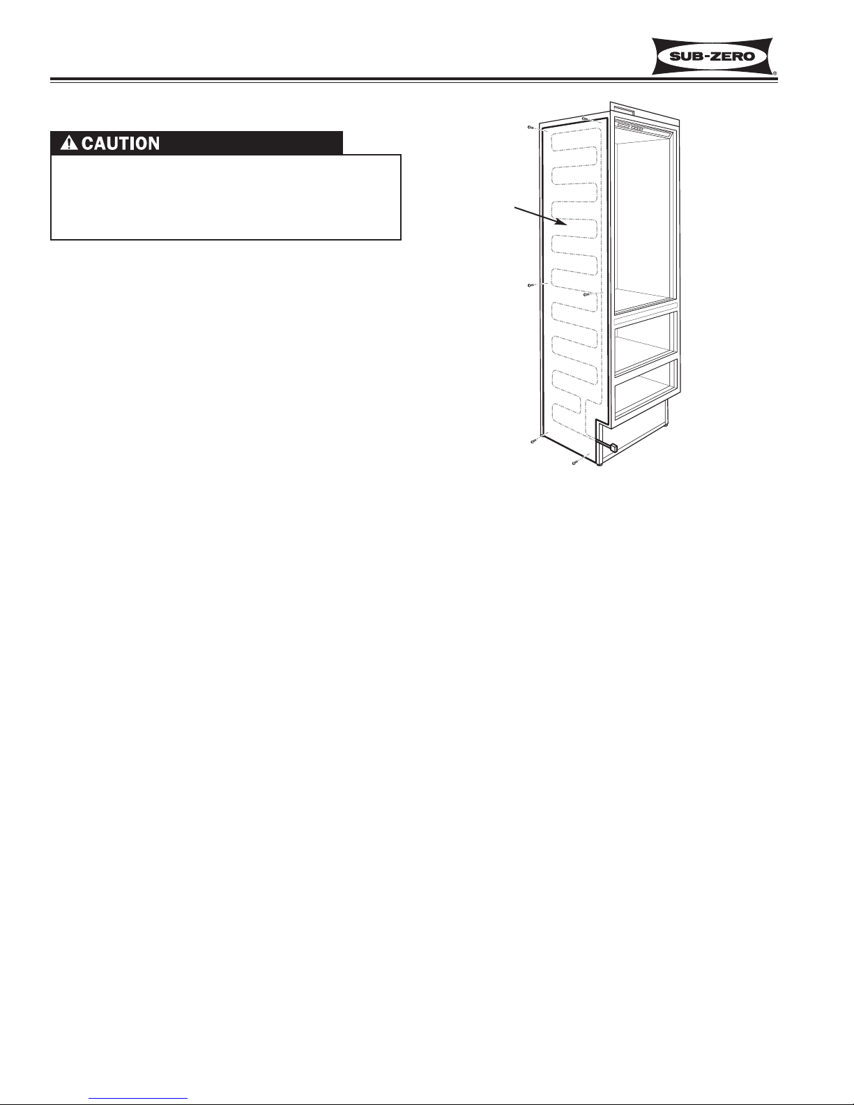
Dual Unit Installations
• If two Tall units are installed side by side and are 2”
or less apart, part #TTDUAL should be utilized.
(See Figure 2-6)
• If two Base units are installed side by side and are
2” or less apart, part #BBDUAL should be utilized
• If a Tall unit is installed next to a Base unit and they
are 2” or less apart, part #BBDUAL should be utilized.
Complete installation instructions are supplied with the
#BBDUAL and #TTDUAL packages.
Figure 2-6. Dual Unit Heater (#TTDUAL Shown)
Apply heater
to left side of
right hand
unit
If two or more units are placed side by side and are
2” or less apart, a dual unit heater package must be
applied to the left side of the right hand unit.
Failure to install the dual unit heater package could
result in exterior condensation between the units.
Page 15

Integrated
Integrated
(700-
(700-
3
3
TTALL)
ALL)
Series
Series
Electronic Control System
3-1
#3758412 - Revision B - December, 2006
SECTION 3
ELECTRONIC CONTROL
SYSTEM INFORMATION
Page 16
Electronic Control System
Integrated
Integrated
(700-
(700-
3
3
TTALL)
ALL)
Series
Series
3-2
#3758412 - Revision B - December, 2006
ELECTRONIC CONTROL TERMINOLOGY & COMPONENT DESCRIPTIONS
The electronic control system monitors, regulates and controls a variety of functions. It also displays temperature
readings, ice maker system operational status, possible problems with the unit and door ajar alarm status. The table
below defines some basic electronic control system terminology and describes some of the electronic control system
components. An understanding of the following information is needed in order to comprehend the input operations
and functions of the electronic control system.
T
erm/Component Definition / Description
Control Board ……………………..…….. The printed-circuit board (PC Board) contains the microprocessor, relays and
electrical connections which control and monitor all functions and operations of
the appliance.
Microprocessor ……………………..…... An electrical component on the control board which receives electrical signals
from other components, processes that information, then sends an electrical signal to the relays on the board to open or close, and other electronic components
in the unit to switch on or off.
Relay ………………………………..…… The electrical components on the control board which switch other components in
the unit ON and OFF when instructed to do so by the microprocessor.
LCD (Liquid Crystal Display) …..…...... That part of the control board seen at the control panel which displays zone tem-
peratures, service indicator, door ajar alarm bell & ice indicator.
Control Panel Assembly ……..………… The information input and read-out area of the electronic control system, located
at the top of the upper Compartment.
Membrane Switch …………..………….. An integral part of the control panel assembly, which consists of the function keys
used for all input operations to the electronic control system.
Keys (Function Keys) ………..………… The buttons on the Membrane switch used for input operations. (The keys are:
UNIT ON/OFF, ALARM ON/OFF, ICE ON/OFF, WARMER, COLDER)
Indicators .....…………………..………... The words and numbers that are displayed at the control panel assembly.
(Example: Temperature displays, alarm bell indicator, SERVICE indicator, and ICE
system indicator)
Error Codes .…………………..………... The code numbers accompanied by the letters “EC” that appear on the LCD dur-
ing diagnostic mode if the unit experienced specific problems related to electrical
signals supplied by electrical components.
Display Units of Measure…………..…... Temperatures displayed at the LCD may be in fahrenheit units of measure (°F) or
celsius units of measure (°C). A series of key strokes allows the temperature display units of measure to be switched to read as either °F or °C.
Set-Point …………………………..…….. The desired zone temperature, established by pressing the COLDER or
WARMER keys.
High Offset (Cut-in)……………..……..... As the zone air temperature cycles up and down, the high offset is the maximum
zone temperature that the electronic control system will allow before calling for
cooling.
Low Offset (Cut-out)……………..……... As the zone air temperature cycles up and down, the low offset is the minimum
zone air temperature that the electronic control system will allow before interrupting cooling.
Thermistor (Temperature Sensor) ..….. A resistor with which resistance changes as the temperature around it changes.
For electronic control system purposes, the microprocessor measures this resistance and displays it as a temperature reading at the LCD.
Variable Speed Compressor ….............. A compressor that runs at varying speeds depending on the load detected by the
compressor’s inverter.
Page 17
Integrated
Integrated
(700-
(700-
3
3
TTALL)
ALL)
Series
Series
Electronic Control System
3-3
#3758412 - Revision B - December, 2006
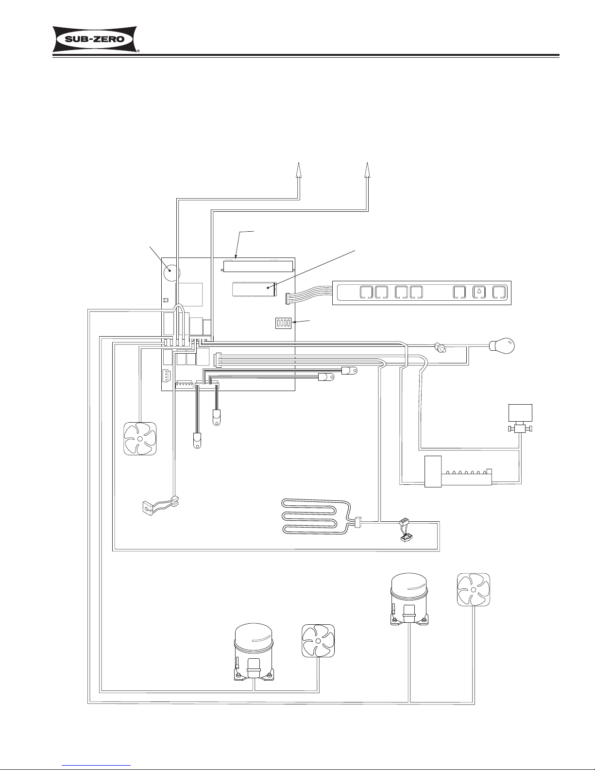
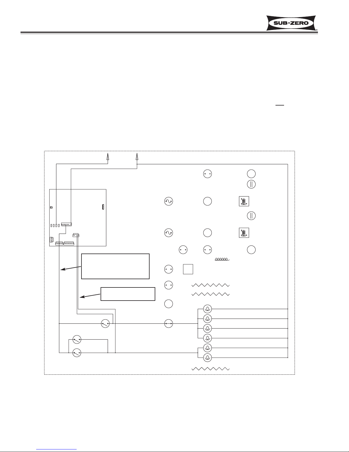
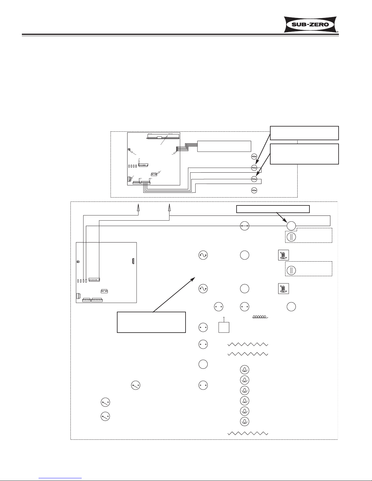
Figure 3-1. Basic 700TCI-3 Electronic Control System Diagram
BASIC ELECTRONIC CONTROL SYSTEM
Input operations for the electronic control system are performed at the control panel (located at the top of the upper
compartment), with monitoring, regulating and controlling functions taking place at the control board (located directly
behind the control panel). Temperatures and possible problems with the unit are illuminated in the control panel at
the LCD. This page illustrates a basic 700 Series electronic control system (Model 700TCI-3 used, See Figure 3-1).
The entire electronic control system is described in greater detail on the following pages.
ALARM BELL
COND
FAN
R RRR
FILL TUBE
HEATER
RRRR
FRE CMPRTMNT
THERMISTOR
CONTROL BOARD
LCD
FRE EVAP
THERMISTOR
DEFROST
HEATER
L1
115 VOLTS
60 CYCLES
MICROPROCESSOR
CONTROL PANEL / MEMBRANE SWITCH
FREEZER
BOARD CONFIGURING
RESISTORS
REF EVAP
THERMISTOR
REF CMPRTMNT
THERMISTOR
NEUT
WARMERCOLDER
DEFROST MONITOR LINE
WARMERCOLDER
REFRIGERATOR
LIGHT
SWITCH
SOL. MONITOR LINE
DEFROST TERMINA T OR
ICE
ON/OFF
ON/OFF
DOOR AJAR
MONITOR LINE
WATER
SOLENOID
ICEMAKER
LIGHTS
ON/OFF
UNIT
FREEZER
COMP
FREEZER
EVAP FAN
REFRIG
COMP
REFRIG
EVAP FAN
Page 18
Electronic Control System
Integrated
Integrated
(700-
(700-
3
3
TTALL)
ALL)
Series
Series
3-4
#3758412 - Revision B - December, 2006
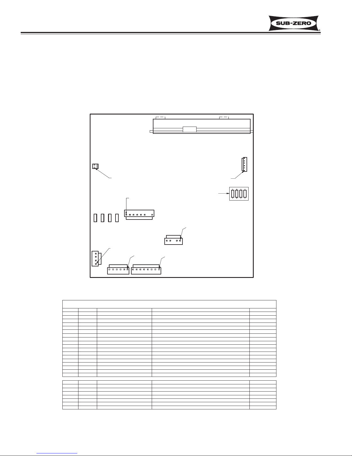
Figure 3-2. 700-3 Tall Unit Control Board Layout
Figure 3-3. 700-3 Tall Unit Control Board Summary Table (700TC/I-3 Summary Table Shown)
CONTROL BOARD LAYOUT AND SUMMARY TABLE
The electrical connection points on the control board are labeled alphanumerically. These labels correspond with
the alphanumeric control board summary table, located on the wiring diagrams. By referencing the summary table,
it is possible to identify which components are connected at which connection points on the control board. Below is
a layout diagram of the control board, and a copy of a summary table. (See Figures 3-2 and 3-3)
NOTE: All components on the control board are non-replaceable. If a problem with the control board is identified,
the complete control board must be replaced.
LCD (DISPLAY)
J5
PIN 1
PIN 1
BOARD CONFIGURING
RESISTORS
J6
PIN 1
J7
E7 E10 E6E2
PIN 1
J4
J3
CIRCUIT
DEF HTRE2
E7
FCOMP
E10
E6
J7-1 C FAN
J7-2
J7-3
J7-4
J7-5
J7-6
J7-7
J7-8
J4-1
J4-2
J4-3
J4-4
J4-5
LOW VOLTAGE THERMISTOR CIRCUITS
J1-1
J1-2
J1-3
J1-4
J1-5
J1-6
J1-7
J1-8
L1
RCOMP
E FAN
IACC
LITES
ICE
NEU
F DR
R DR
EVAP FRZ
EVAP FRZ
EVAP REF
EVAP REF
REF
REF
FRZ
FRZ
PIN 1
J2
PIN 1
J1
PIN 1
DESCRIPTION
120 VOLT CIRCUITS
DEFROST HEATER
FRZ COMPRESSOR
POWER IN
REF COMPRESSOR
CONDENSER FAN
NOT USED
ICE MAKER ACC (FILL TUBE)
LIGHTS
ICE MAKER POWERS ICE MAKER
NOT USED
NOT USED(NO PIN)
NEUTRAL
DRAWER LIGHTS SENSE
DOOR LIGHTS SENSE
NOT USED(NO PIN)
DEF SENSOR
ICE MAKER VALVE SENSOR
FRZ EVAP
FRZ EVAP
REF EVAP
REF EVAP
REF COMPARTMENT
REF COMPARTMENT
FRZ COMPARTMENT
FRZ COMPARTMENT
CONTROL BOARD SUMMARY
FUNCTION COLOR
POWERS DEFROST CIRCUIT
POWERS FRZ COMPRESSOR (DRAWERS)
POWER INTO BOARD
POWERS REF COMPRESSOR (DOOR)
POWERS CONDENSER FAN
POWERS FILL TUBE HEATER AND ACCESSORIES
POWERS LIGHTS
NEUTRAL INTO BOARD
SENSES IF EITHER DRAWER OPEN
SENSES IF DOOR OPEN
SENSES WHEN DEF HEATER SHUTS OFF
SENSES WATER VALVE ACTIVATION
SENSES FRZ EVAP TEMP (DRAWERS)
SENSES FRZ EVAP TEMP (DRAWERS)
SENSES REF EVAP TEMP
SENSES REF EVAP TEMP
SENSES REF CABINET TEMP
SENSES REF CABINET TEMP
SENSES FRZ CABINET TEMP (DRAWERS)
SENSES FRZ CABINET TEMP (DRAWERS)
BLUE
PURPLE
BLACK
GRAY
WHITE/RED
WHITE/BLUE
YELLOW
PINK
WHITE
ORANGE
ORANGE
GRAY/WHITE
TAN
ORANGE/RED
BLUE/RED
ORANGE/YEL
BLUE/YELLOW
BLUE/WHITE
BLUE/WHITE
BLUE/BLACK
BLUE/BLACK
Page 19
Integrated
Integrated
(700-
(700-
3
3
TTALL)
ALL)
Series
Series
Electronic Control System
3-5
#3758412 - Revision B - December, 2006
UNIT
ICE
WARMER
COLDER
REFRIGERATOR
ON/OFF
ON/OFF
ON/OFF
WARMER
COLDER
FREEZER
ICE
SERVICE
OFF
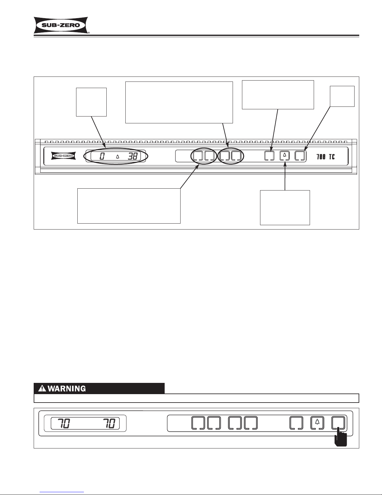
CONTROL PANEL LAYOUT
Please note that an illustration of the 700TC/I-3 control panel is used in most cases for this section. (See Fig. 3-4)
Figure 3-4. 700-3 Tall Unit Control Panel Layout (700TC/I-3 Control Panel Shown)
WHEN IN OFF MODE, 115 VOLTS AC IS STILL PRESENT AT CONTROL BOARD!
Figure 3-5. 700-3 Tall Unit ON/OFF, Press UNIT ON/OFF Key
BASIC ELECTRONIC CONTROL INPUT OPERATIONS
Following are illustrations which show the basic input operations performed at the control panel. Switching the unit
ON and OFF, adjusting the set-point (temperature adjustments), switching the ice maker system ON and OFF, and
enabling and disabling the door ajar alarm feature will be explained. Please note that an illustration of the 700TC/I-3
control panel is used for most articles in this section, and in most cases Fahrenheit readings are shown.
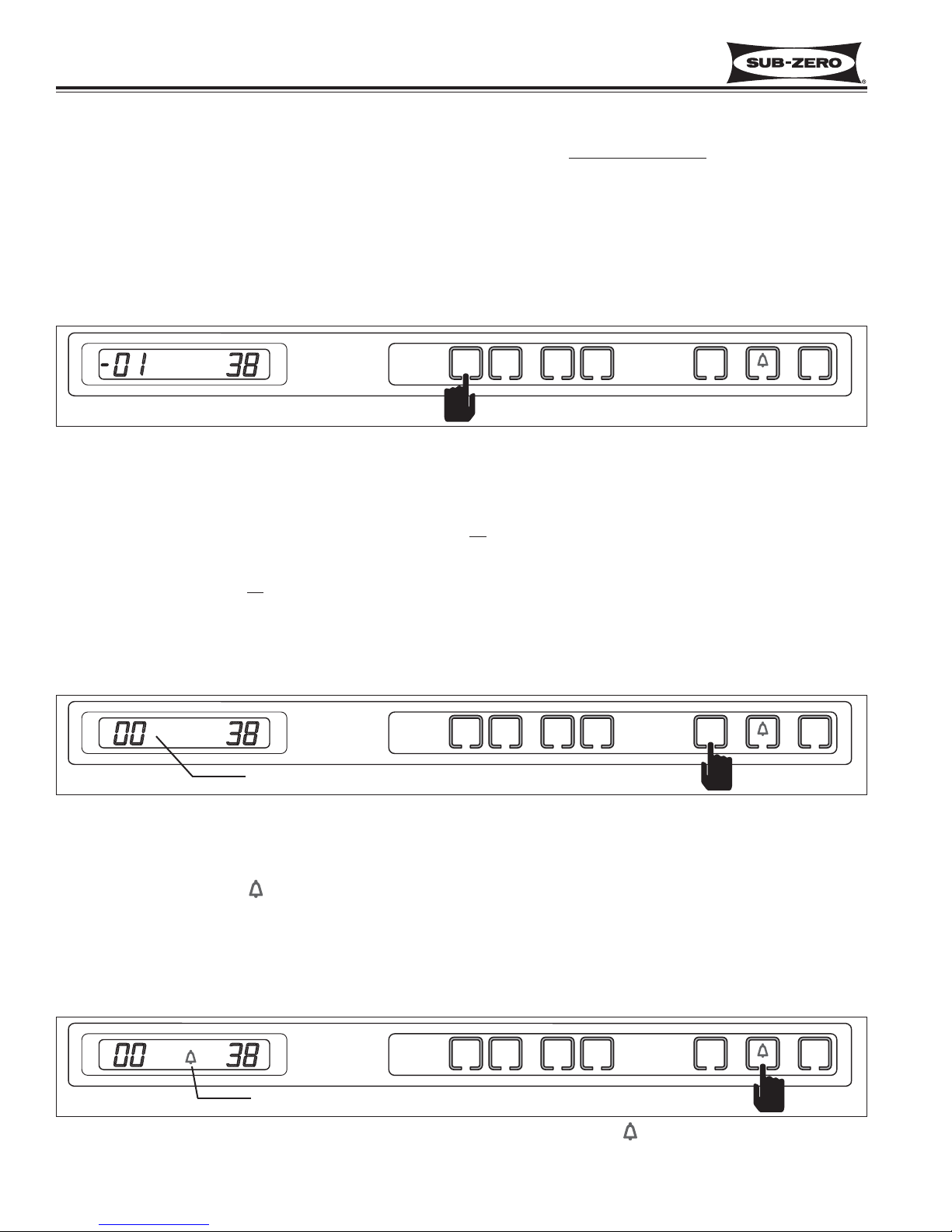
Unit ON/OFF
All units are shipped in OFF Mode. When power is supplied to the unit, a trace of the word “OFF” is visible on the
LCD. By pressing and releasing the UNIT ON/OFF key (See Figure 3-5), power is allowed past the control board to
the rest of the unit. This is indicated by the unit’s lights energizing and LCD at the control panel illuminating with
temperature readings.
NOTE: Whenever the unit is switched OFF using the UNIT ON/OFF key, a trace of the word “OFF” will be visible on
the LCD as long as there is power to the unit.
UNIT
ON/OFF
KEY
DOOR / DRAWER
AJAR
ALARM
ON/OFF
KEY
REFRIGERATOR
SET-POINT
ADJUSTMENT
KEYS
(Upper Section on 700TR-3 & 736TR-3)
(Not present on 700TF/I-3)
FREEZER
SET-POINT
ADJUSTMENT
KEYS
(Lower Section on 700TR-3 & 736TR-3)
LCD
Liquid
Crystal
Display
ICEMAKER SYSTEM
ON/OFF KEY
(Not present on
700TR-3 & 736TR-3)
SERVICE
ICE
Jake Dog was here
OFF
FREEZER
COLDER
WARMER
COLDER
WARMER
REFRIGERATOR
ON/OFF
ICE
ON/OFF
ON/OFF
UNIT
FREEZER
WARMERCOLDER
WARMERCOLDER
REFRIGERATOR
ICE
ON/OFF
ON/OFF
UNIT
ON/OFF
Page 20
Electronic Control System
Integrated
Integrated
(700-
(700-
3
3
TTALL)
ALL)
Series
Series
3-6
#3758412 - Revision B - December, 2006
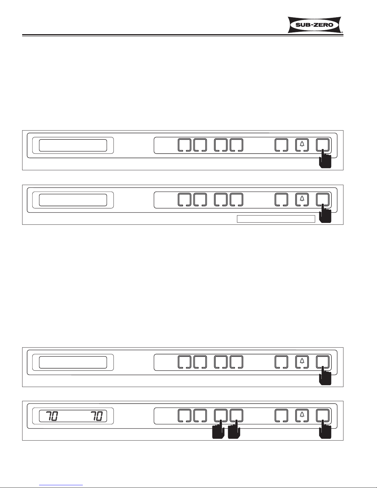
Adjusting Set-Point (Temperature Adjustment)
To adjust set-points, press WARMER or COLDER key on control panel in multiple key strokes
until desired set-point
is achieved (See Figure 3-6). One key stroke equals one degree change.
NOTE: The temperature range in a freezer zone is -5°F (-21°C) to +5°F (-15°C). The temperature range in a refrigerator zone is +34°F (+1°C) to +45°F (+7°C).
NOTE: The initial stroke of the WARMER or COLDER key will change the previous set-point by one degree.
NOTE: The set-point will be displayed on the LCD for 10 seconds after the last key stroke. After the 10 second
delay, the zone temperature will be displayed. As the zone temperature changes, the temperature displayed on the
LCD will change by no more than one degree per minute.
Figure 3-6. Adjusting Set-Point - Press WARMER or COLDER Key In Multiple Key Strokes
Icemaker System ON/OFF
When a unit first arrives in a home, the icemaker system is off. By pressing and releasing the ICE ON/OFF key,
power is allowed to the icemaker system and “ICE” appears on the LCD (See Figure 3-7). To switch the icemaker
system off, press and release the ICE ON/OFF key again and the “ICE” indicator disappears from the LCD, indicating the icemaker system is of
f.
NOTE: When in “Sabbath Mode,” the icemaker system is deactivated. Sabbath Mode will be explained later.
NOTE: To allow ice to freeze fully and reduce effects of low water pressure, power to the icemaker system is inter-
rupted for 45 minutes after each ice harvest. This can be bypassed for service purposes by switching the icemaker
system OFF, then back ON with the ICE ON/OFF key.
Figure 3-7. Icemaker System ON/OFF - Press ICE ON/OFF Key
Ice system active if “ICE” is displayed
Door Ajar Alarm Feature ( ) ON/OFF
All units are equipped with a door ajar alarm feature. To enable the door ajar alarm, press and release the Alarm
Bell ON/OFF key on the control panel (See Figure 3-8). The bell indicator appears on the LCD indicating the alarm
feature is active. With the alarm enabled, the bell indicator will flash and an audible alarm will beep whenever the
door is left open for more then thirty seconds. To disable the door ajar alarm, press the Alarm Bell ON/OFF key
again and the bell indicator disappears from the LCD, indicating the alarm feature is inactive.
Door Ajar Alarm active if Bell is displayed
Figure 3-8. Switching Door Ajar Alarm ON or OFF - Press ( )ON/OFF Key
FREEZER
WARMERCOLDER
WARMERCOLDER
REFRIGERATOR
ICE
ON/OFF
ON/OFF
UNIT
ON/OFF
ICE
FREEZER
WARMERCOLDER
WARMERCOLDER
REFRIGERATOR
ICE
ON/OFF
ON/OFF
UNIT
ON/OFF
FREEZER
WARMERCOLDER
WARMERCOLDER
REFRIGERATOR
ICE
ON/OFF
ON/OFF
UNIT
ON/OFF
Page 21
Integrated
Integrated
(700-
(700-
3
3
TTALL)
ALL)
Series
Series
Electronic Control System
3-7
#3758412 - Revision B - December, 2006
UNIQUE ELECTRONIC CONTROL INPUT OPERATIONS
The following pages illustrate unique input operations performed at the control panel that you would not expect a
customer to perform every day. The input operations described are: Temperature Unit Selection Mode, Sabbath
Mode, Showroom Mode, Manual Zone Disable Mode and Manual Freezer Evaporator Defrost.
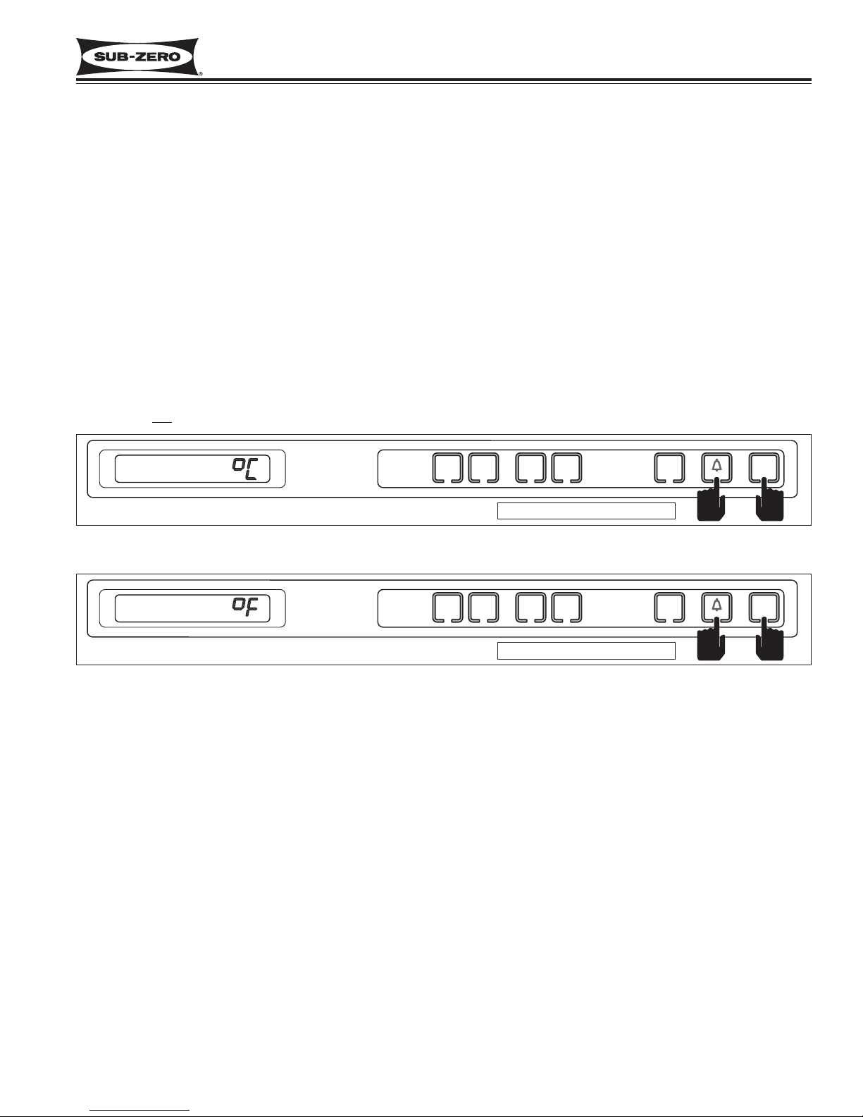
Temperature Units Selection Mode (Selecting Degrees Fahrenheit or Degrees Celsius Display)
The electronic control is initially set to display temperature in Fahrenheit (°F) units of measure. Units of measure
can be converted from °F to °C (Celsius), and/or back again. This operation is called Temperature Units Selection.
NOTE: Temperature Units Selection must be performed within the first minute after switching the unit ON.
To convert temperature units of measure from Fahrenheit (°F) to Celsius (°C) readings, press and hold the door ajar
alarm bell ON/OFF key and the UNIT ON/OFF key simultaneously for five (5) seconds, then release the keys (See
Figure 3-9). “ °C “ will appear on the LCD indicating that temperatures will now be displayed in Celsius units of
measure. To convert back to Fahrenheit units of measure, repeat the steps above (See Figure 3-10).
NOTE: Temperature Units Selection Mode will end ten (10) seconds after the last key stroke.
NOTE: Do not
press and hold the UNIT ON/OFF key first, that will simply switch the unit OFF.
Figure 3-10. Converting Back to Fahrenheit Units of Measure
(within ten (10) seconds of previous key stroke and/or within first minute after switching unit ON)
Press and Hold the Door Ajar Alarm Bell Key and The UNIT ON/OFF Keys
Figure 3-9. Converting to Celsius Units of Measure (within first minute after switching unit ON)
Press and Hold the Door Ajar Alarm Bell Key and The UNIT ON/OFF Keys for Five (5) Seconds
Press and hold for 5 seconds
Press and hold for 5 seconds
FREEZER
WARMERCOLDER
WARMERCOLDER
REFRIGERATOR
ICE
ON/OFF
ON/OFF
UNIT
ON/OFF
FREEZER
WARMERCOLDER
WARMERCOLDER
REFRIGERATOR
ICE
ON/OFF
ON/OFF
UNIT
ON/OFF
Page 22
Electronic Control System
Integrated
Integrated
(700-
(700-
3
3
TTALL)
ALL)
Series
Series
3-8
#3758412 - Revision B - December, 2006
Figure 3-12. Then Press and Hold UNIT ON/OFF Key for 10 Seconds
Showroom Mode
Showroom Mode was incorporated into the electronic control system so that units could be displayed in a showroom
setting. When in Showroom Mode, all cooling functions are disabled, but the lighting system remains active.
To initiate Showroom Mode, the unit must first be switched OFF using the UNIT ON/OFF key (See Figure 3-13),
then press and hold either pair of WARMER and COLDER keys, then the UNIT ON/OFF key, then release all three
keys (See Figure 3-14). To return the unit to normal operation, repeat the steps above.
NOTE: Always check set-points after returning unit to normal operation.
NOTE: It is possible to determine if a unit is in Showroom Mode by initiating Diagnostic Mode. If “Sr” is observed in
the left temperature display area during Diagnostic Mode, the unit is in Showroom mode. Initiating Diagnostic Mode
is covered later in this section.
Figure 3-14. Then Press and Hold WARMER and COLDER Keys, Then the UNIT ON/OFF Key
Figure 3-13. To Enter (or Exit) Showroom Mode, Switch Unit OFF First
Press and hold for 10 seconds
Sabbath Mode
Sabbath Mode was incorporated into the electronic control system for the observance of certain religious days.
Initiating Sabbath Mode disables the LCD, lighting system, ice making system and door ajar alarm feature.
To initiate Sabbath Mode, the unit must first be switched OFF using the UNIT ON/OFF key (See Figure 3-11), then
press and hold the UNIT ON/OFF key until the LCD and lights switch OFF, approximately ten (10) seconds (See
Figure 3-12). To return to normal operation, press and release the UNIT ON/OFF key.
NOTE: During Sabbath Mode, the LCD is disabled and set-points cannot be changed.
NOTE: During Sabbath Mode, the compartment thermistors still control compressor operation, except when high
offset is reached, there is a random fifteen (15) to twenty-five (25) second delay before compressors are energized.
Figure 3-11. To Enter Sabbath Mode, Switch Unit OFF First
OFF
FREEZER
WARMERCOLDER
WARMERCOLDER
REFRIGERATOR
ICE
ON/OFF
ON/OFF
UNIT
ON/OFF
FREEZER
WARMERCOLDER
WARMERCOLDER
REFRIGERATOR
ICE
ON/OFF
ON/OFF
UNIT
ON/OFF
OFF
FREEZER
FREEZER
WARMERCOLDER
WARMERCOLDER
WARMERCOLDER
WARMERCOLDER
REFRIGERATOR
REFRIGERATOR
ICE
ON/OFF
ICE
ON/OFF
ON/OFF
ON/OFF
UNIT
ON/OFF
UNIT
ON/OFF
Page 23
Integrated
Integrated
(700-
(700-
3
3
TTALL)
ALL)
Series
Series
Electronic Control System
3-9
#3758412 - Revision B - December, 2006
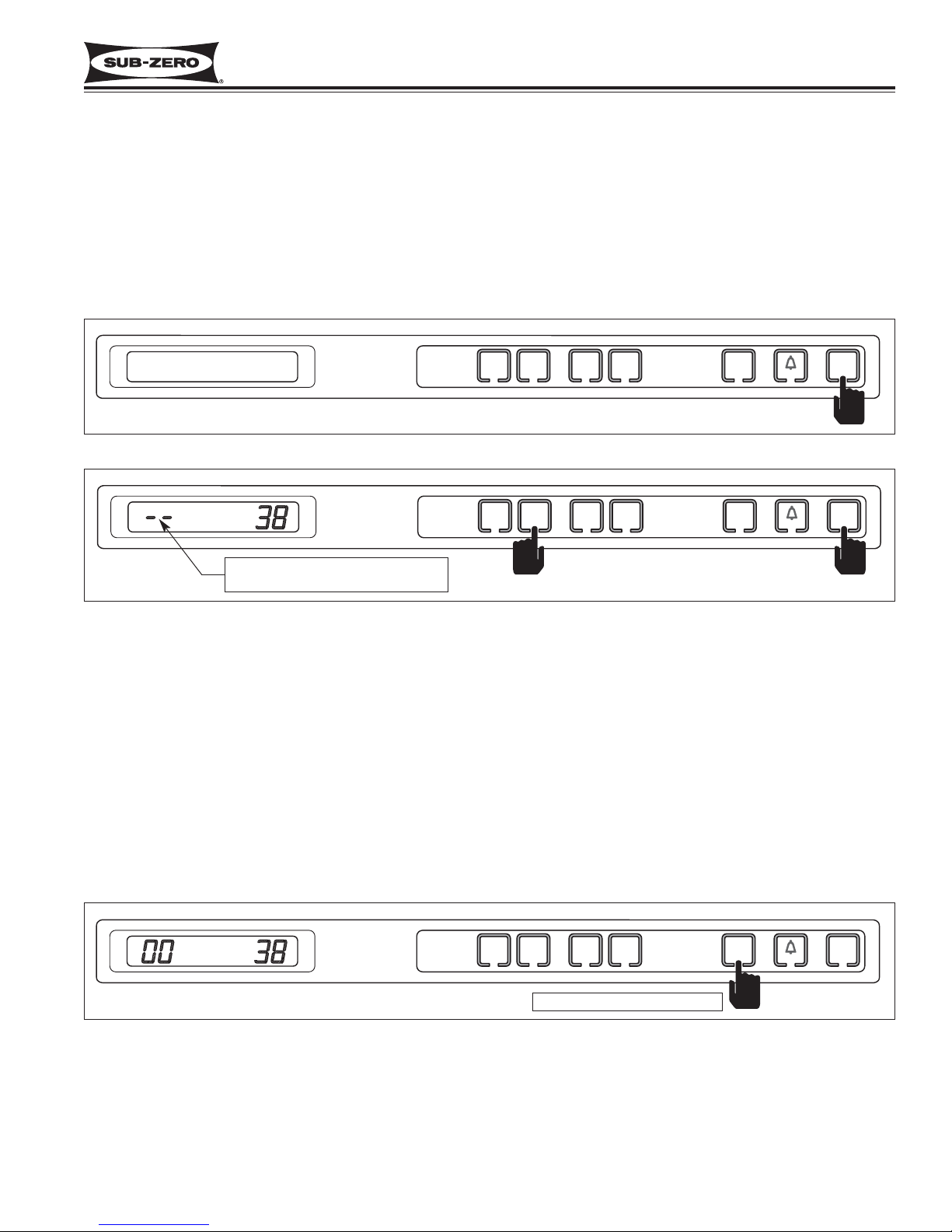
Manual Zone Disable Mode
Manual Zone Disable Mode allows a customer or Service Technician to switch one zone off for interior cleaning,
defrosting, or diagnostic purposes, while allowing the other zone to continue cooling.
To initiate Manual Zone Disable Mode, the unit must first be switched OFF using the UNIT ON/OFF key (See Figure
3-15), then press and hold the WARMER key for the zone being disabled, then the UNIT ON/OFF key, then release
both keys (See Figure 3-16). The LCD will display “- -” (double dashes) in place of temperature readings for the
zone chosen, indicating all cooling functions for that zone are disabled. To return the unit to normal operation,
repeat the steps above, or press UNIT ON/OFF key.
NOTE: Always check set-points after returning unit to normal operation.
Figure 3-16. Then Press and Hold WARMER Key for Zone Being Disabled,
Then the UNIT ON/OFF Key.
Figure 3-15. To Enter (or Exit) Manual Zone Disable Mode, Switch Unit OFF First
Indicating that all cooling functions
for that zone are disabled.
Manual Freezer Evaporator Defrost
Manual Freezer Evaporator Defrost was incorporated into the electronic control to assist in servicing and diagnostics.
To initiate manual freezer evaporator defrost, press and hold the ICE ON/OFF key for five (5) seconds, then release
the key. (See Figure 3-17).
NOTE: Manual Freezer Evaporator Defrost will not operate if unit is in Sabbath Mode.
Figure 3-17. Initiate Manual Freezer Evaporator Defrost - Press and Hold ICE ON/OFF key for 5 Seconds
Press and hold for 5 seconds
OFF
FREEZER
WARMERCOLDER
WARMERCOLDER
REFRIGERATOR
ICE
ON/OFF
ON/OFF
UNIT
ON/OFF
FREEZER
WARMERCOLDER
WARMERCOLDER
REFRIGERATOR
ICE
ON/OFF
ON/OFF
UNIT
ON/OFF
ICE
FREEZER
WARMERCOLDER
WARMERCOLDER
REFRIGERATOR
ICE
ON/OFF
ON/OFF
UNIT
ON/OFF
Page 24
Electronic Control System
Integrated
Integrated
(700-
(700-
3
3
TTALL)
ALL)
Series
Series
3-10
#3758412 - Revision B - December, 2006
FUNCTIONS OF THE ELECTRONIC CONTROL SYSTEM
The following pages explain monitoring, regulating and controlling functions of the electronic control system. In most
cases signal traces of a model 700TCI-3 wiring schematic are used to show current flow for functions being
explained.
Supply Power to the Lighting System
115 Volts AC are supplied to the lighting system through the control board when the unit is switched ON
by pressing
the UNIT ON/OFF key. With the doors open, the light switches allows power to the lights (See Figure 3-18).
NOTE: 115 Volt AC signal to the lights is monitored by the microprocessor to control the door ajar alarm feature.
NOTE: If in Sabbath Mode, th lighting system is disabled. Sabbath Mode will be covered later.
Figure 3-18. 700TC/I-3 Signal Trace Schematic of Lighting System
115 Volts are supplied
through J7 to lighting system
unless unit is switched OFF
or is in Sabbath Mode
NOTE:
Door Ajar Sense Lines
HIGH VOLTAGE
115 VOLTS
BLACK
WHITE
L1
60 CYCLES
NEUT
WHITE
M
J5
E2 E7 E10 E6
J3
J6
J7
J4
J1
J2
M
M
M
ORANGE
ORANGE
REFRIGERATOR
LIGHT SWITCH
ORANGE
ORANGE
FREEZER
LIGHT
SWITCHES
ORANGE
ORANGE
LIGHT
TERMINATOR
M
REFRIGERATOR
LIGHTS
FREEZER
LIGHTS
Page 25
Integrated
Integrated
(700-
(700-
3
3
TTALL)
ALL)
Series
Series
Electronic Control System
3-11
#3758412 - Revision B - December, 2006
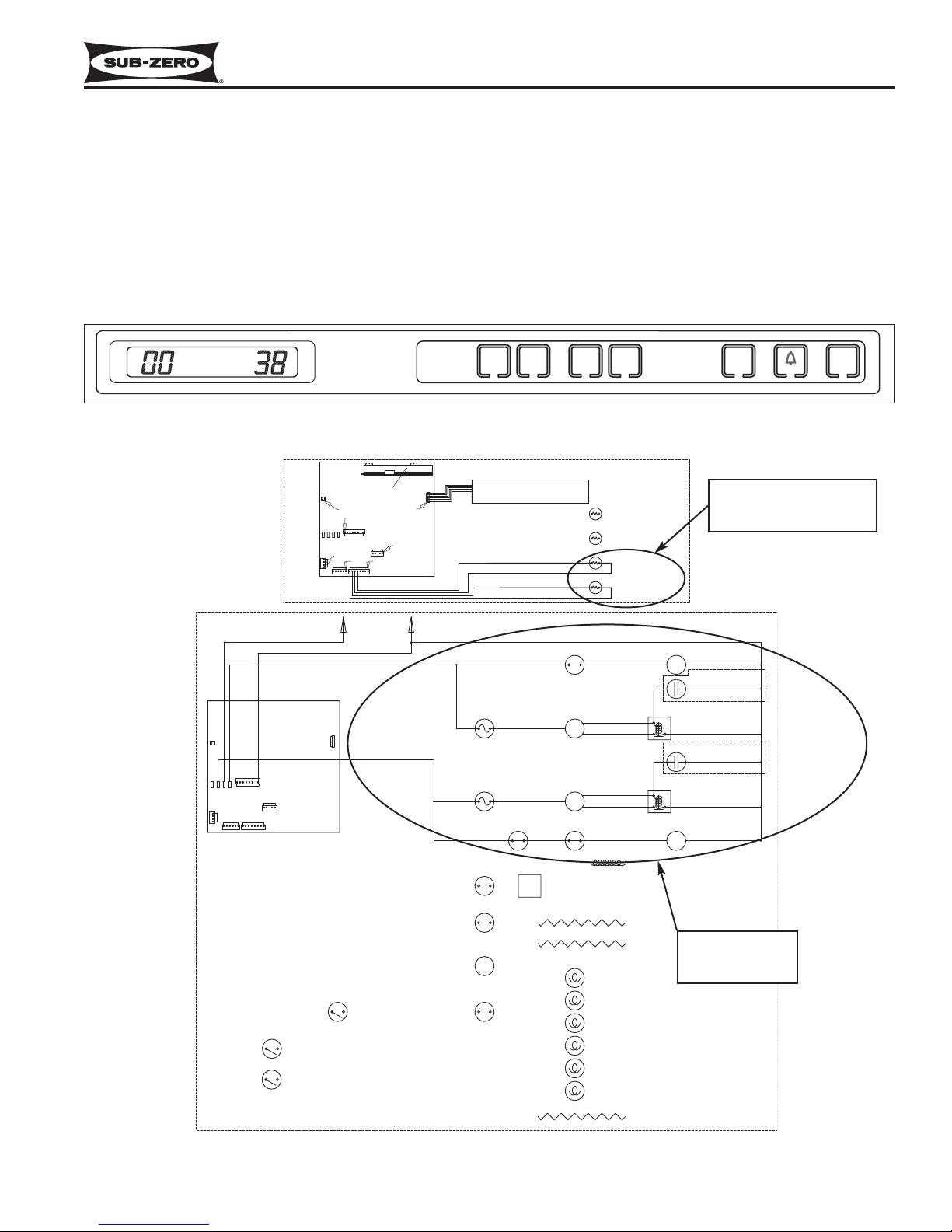
Monitor, Regulate and Display Compartment Temperatures
The temperature signal from the compartment thermistor is monitored by the microprocessor and then displayed on
the LCD. Though the compartment air temperature does fluctuate, the LCD displays the average temperature (See
Figure 3-19). When the compartment temperature reaches high offset, the microprocessor supplies power to the
compressor and evaporator fan (See Figure 3-20). As the compressor and evaporator fan run, the compartment
temperature drops. When the compartment temperature reaches low offset, the microprocessor interrupts power to
the compressor and evaporator fan, cycling them off.
NOTE: If the average compartment temperature changes, the temperature displayed on the LCD will change by one
degree per minute.
Figure 3-19. Average Compartment Temperature Displayed
Compartments
calling for cooling
(Temp. above high offset)
Compressors and
evaporator fans
energized
Figure 3-20. 700TC/I-3 Signal Trace Schematic (High & Low Voltage) of Regulating Temperatures
HIGH VOLTAGE
J5
E2 E7 E10 E6
J3
J2
FREEZER
WARMERCOLDER
WARMERCOLDER
LOW VOLTAGE
DISPLAY
J5
0
PIN 1
PIN 1
J7
0
E2 E6E10E7
J3
PIN 1
J2
0
L1
BLACK
WHITE
J7
J4
J1
J6
GRAY
0
115 VOLTS
60 CYCLES
J1
0
PURPLE
J6
0
PIN 1
PIN 1
0
J4
PIN 1PIN 1
NEUT
MEMBRANE SWITCH
BLUE W/WHITE STRIPE
BLUE W/WHITE STRIPE
BLUE W/BLACK STRIPE
BLUE W/BLACK STRIPE
WHITE
REFRIGERATOR
FAN SWITCH
REFRIGERATOR
COMPRESSOR
M
REFRIGERATOR
OVERLOAD
PROTECTOR
FREEZER
OVERLOAD
PROTECTOR
FREEZER
FAN
PURPLE RED
SWITCHES
FREEZER
COMPRESSOR
M
REF CAB
THERMISTOR
FZR CAB
THERMISTOR
RED
REFRIGERATOR
REFRIGERATOR
FAN MOTOR
M
RUNNING
CAPACITOR
(WHEN USED)
STARTING
RELAY
RUNNING
CAPACITOR
(WHEN USED)
STARTING
RELAY
FREEZER
FAN MOTOR
M
ICE
ON/OFF
ON/OFF
UNIT
ON/OFF
M
Page 26
Electronic Control System
Integrated
Integrated
(700-
(700-
3
3
TTALL)
ALL)
Series
Series
3-12
#3758412 - Revision B - December, 2006
Assist in Control of Variable Speed Compressors (700TF/I-3 Only)
As mentioned on the previous page, temperature signals from the thermistors in the compartment are monitored by
the microprocessor and then displayed on the LCD.
When the compartment reaches high-offset (calling for cooling), an “ON” signal is sent from the control board to the
compressor’s inverter. The inverter (which is supplied with AC power at all times) then provide high DC voltage (3phase, 50 - 150 Hz), outputs to the compressor. The inverter in turn senses the compressor load. If the compressor
load is high, the speed command from the inverter will be for high speed compressor operation; if medium compressor load, speed command from the inverter will be for medium speed; if low compressor load, speed command from
the inverter will be for low speed. If/when the compartment reaches low-offset, an “OFF” signal is sent to the inverter, which then cuts DC power to the compressor.
NOTE:
• The variable speed compressor, evaporator fan and the condenser fan will run a great majority of the time. This is
normal. These components will only cycle off during defrost and may also cycle off for short periods of time if the
ambient temperature is low enough.
• Initial speed command from an inverter to a compressor are always for High speed.
Figure 3-21. 700TF/I-3 Signal Trace Schematic of Variable Speed Compressor Operation
IN EXCESS OF 200 VOLTS MAY
BE PRESENT AT INVERTER
AND COMPRESSOR!
1. Compartment
temperature
monitored by
microprocessor
3. Inverter supplies
high DC voltage,
3-phase, 50 - 150
Hz signal, based
on compressor
load.
2. When cooling is called for,
115 Volts AC “ON” signal
supplied to compressor
inverter, evaporator fan
and condenser fan.
NOTE: Line voltage
supplied to inverter
at all times.
J5
E2 E7 E10 E6
J3
LOW VOLTAGE
J5
0
PIN 1
PIN 1
J7
0
E2 E6E10E7
J3
PIN 1
PIN 1
J2
0
0
HIGH VOLTAGE
J7
J1
J2
BLACK
WHITE
J4
115 VOLTS
L1
60 CYCLES
BLACK
J6
PURPLE
DISPLAY
PIN 1
J1
0
J4
0
NEUT
PIN 1
PIN 1
J6
0
CONDENSER
FAN MOTOR
MEMBRANE SWITCH
WHITE
M
FREEZER
PURPLE RED
FAN SWITCHES
BLUE W/BLACK STRIPE
BLUE W/BLACK STRIPE
VSPEED
CONTROL
BOX
FRZ CAB
THERMISTOR
M
LT. BLU E
FREEZER
FAN MOTOR
BROWN
BLACK
Page 27
Integrated
Integrated
(700-
(700-
3
3
TTALL)
ALL)
Series
Series
Electronic Control System
3-13
#3758412 - Revision B - December, 2006
Control Condenser Fan Run
In all models except the 700TF/I-3, the microprocessor senses the 115 volt output supplied to both compressors. If
either compressor is running, a signal is sent to the condenser fan relay on the control board to close, supplying
power to the condenser fan. If both compressors are off, the condenser fan is off. (See Figure 3-22)
NOTE: There is only one compressor on the model 700TF/I-3. The condenser fan cycles with this single compressor,
which along with the evaporator fan, will cycle off during defrost and may also cycle off for short periods of time if
the ambient temperature is low enough.
Figure 3-22. 700TC/I-3 Signal Trace Schematic (High Voltage) of Condenser Fan Operation
Power supplied to
condenser fan
motor if one or
both compressors
are running
HIGH VOLTAGE
115 VOLTS
J5
E2 E7 E10 E6
J3
60 CYCLES
BLACK
J7
J4
J1
J2
L1
WHITE
GRAY
J6
PURPLE
NEUT
WHITE
REFRIGERATOR
FAN SWITCH
REFRIGERATOR
COMPRESSOR
M
REFRIGERATOR
OVERLOAD
PROTECTOR
FREEZER
OVERLOAD
PROTECTOR
FREEZER
FAN
PURPLE RED
SWITCHES
FREEZER
COMPRESSOR
M
RED
REFRIGERATOR
FAN MOTOR
M
RUNNING
CAPACITOR
(WHEN USED)
STARTING
RELAY
RUNNING
CAPACITOR
(WHEN USED)
STARTING
RELAY
FREEZER
FAN MOTOR
M
WHITE/RED
CONDENSER
FAN MOTOR
M
Page 28
Electronic Control System
Integrated
Integrated
(700-
(700-
3
3
TTALL)
ALL)
Series
Series
3-14
#3758412 - Revision B - December, 2006
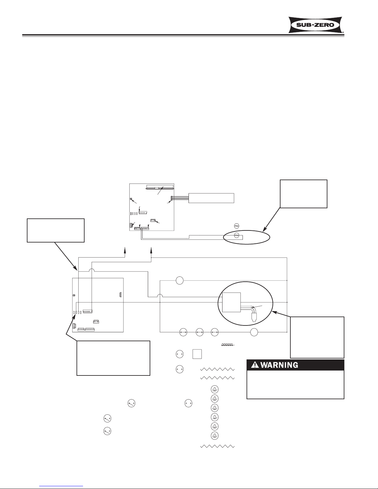
Monitor and Control Refrigerator “Fan-Assisted, Off-Cycle Defrost”
Temperature signals from refrigerator evaporator's thermistor’s are observed by the microprocessor. During off cycle
defrost, if a refrigerator zone temperature reaches high offset (calling for cooling) before evaporator temperature
rises to 38°F (3°C), no power will be supplied the the compressor. But, the the zone evaporator fan will switch ON.
Once the evaporator temperature reaches 38°F (3°C), normal cooling functions begin. (See Figure 3-23).
NOTE: If refrigerator compartment thermistor is faulty, compressor operation defaults to 20 minutes ON, 40 minutes
OFF cycling, EE appears in left of LCD, SERVICE will flash and Error Code 05 will be logged.
NOTE: If evaporator thermistor is faulty, the compressor will not energize until zone air temperature exceeds high
offset by 5°F (3°C). SERVICE flashes and Error Code 06 is logged.
NOTE: When in Sabbath
Mode, the refrigerator compartment thermistor still controls compressor operation,
except there is a random 15
to 25 second delay before
the compressor is energized.
Figure 3-23. 700TC/I-3 Signal Trace Schematic (High & Low Voltage) of Refrigerator Off-Cycle Defrost
J6
J5
J3
E2E7E10
E6
J2
J1
J7
J4
J5
J7
J3
J2
E2
E6
E10
E7
J1
J4
LOW VOLTAGE
J6
HIGH VOLTAGE
NEUT
115 VOLTS
60 CYCLES
L1
REFRIGERATOR
OVERLOAD
PROTECTOR
REFRIGERATOR
COMPRESSOR
BLACK
WHITE
STARTING
RELAY
MEMBRANE SWITCH
DISPLAY
REF EVAP
THERMISTOR
BLUE W/YELLOW STRIPE
BLUE W/WHITE STRIPE
BLUE W/WHITE STRIPE
ORANGE W/YELLOW STRIPE
REF CAB
THERMISTOR
(WHEN USED)
M
M
M
M
M
PIN 1
PIN 1
PIN 1
0
PIN 1
0
0
0
PIN 1
PIN 1
PIN 1
0
0
0
REFRIGERATOR
FAN SWITCH
REFRIGERATOR
FAN MOTOR
RED
1. High offset temperature
reached, calling for
cooling
2. Evaporator temperature
below 38°F (3°C)
4. No power supplied to
refrigerator compressor
circuit
3. Evaporator fan energized
Page 29
Integrated
Integrated
(700-
(700-
3
3
TTALL)
ALL)
Series
Series
Electronic Control System
3-15
#3758412 - Revision B - December, 2006
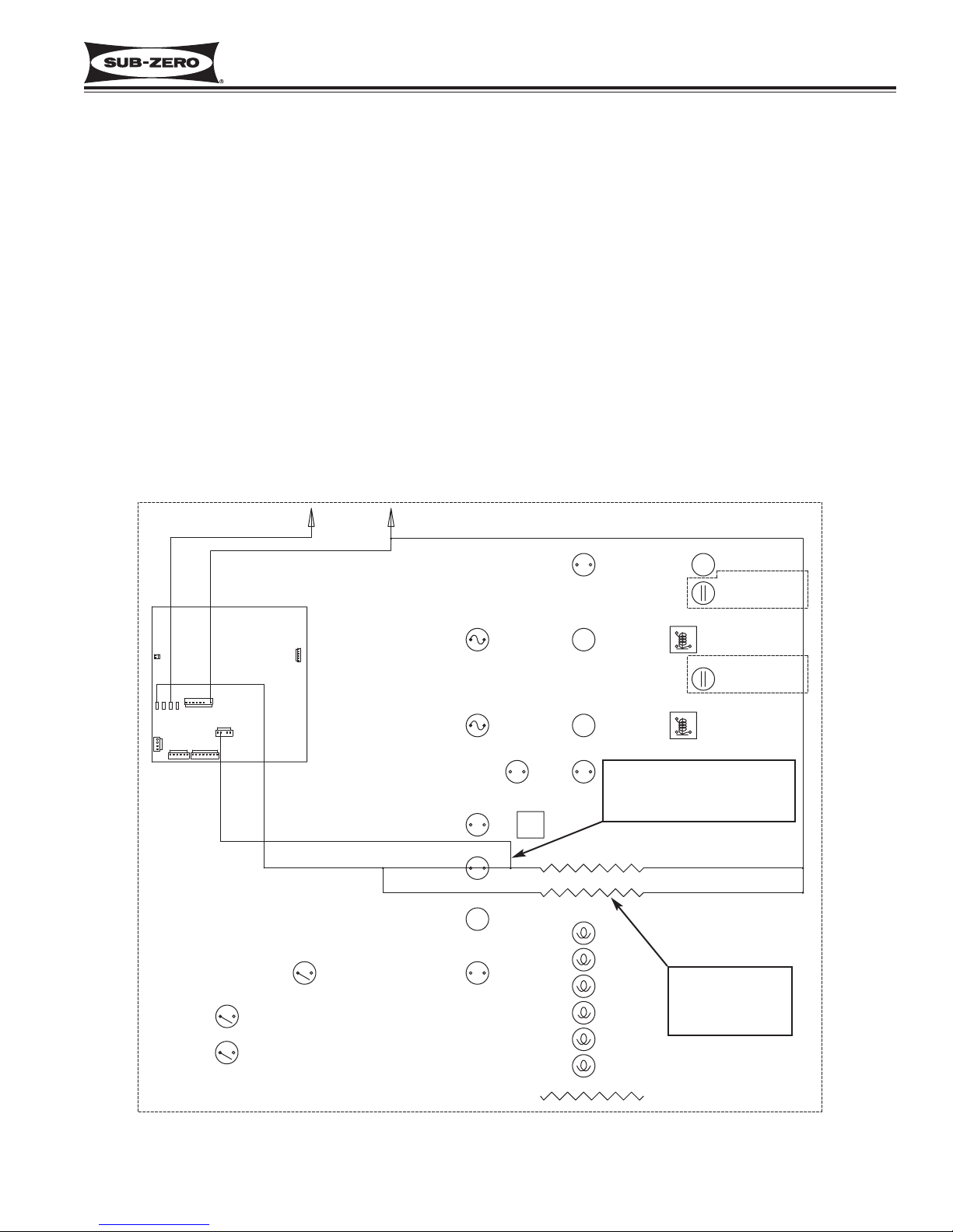
Monitor and Control Freezer “Adaptive Defrost”
Initially the freezer compressor will cycle-run for twelve hours (twenty-four hours in the model 700TF/I-3), after which
the microprocessor sends the signal to the defrost relay on the control board to close. This supplies power to the
defrost heater, and the compressor is switched off (See Figure 3-24). With the “Adaptive Defrost” technique, the
length of time that the heater actually stays on to defrost the evaporator and satisfy the defrost terminator is
observed by the microprocessor. The microprocessor then determines the number of hours before the next defrost.
If the heater stays on for a shorter time than specified, the microprocessor increases the next defrost interval. If the
heater stays on longer than specified, the electronic control decreases the next defrost interval. This is an ongoing
process whereby the defrost time and the defrost interval will vary by unit use.
NOTE: A five (5) minute time delay/dwell follows all defrosts, except in the model 700TF/I-3 where the delay/dwell is
ten (10) minutes. The drain trough heater is energized during defrost and the delay/dwell period.
NOTE: The minimum defrost interval is six (6) hours; The maximum defrost interval is eighty (80) hours; the maximum defrost duration is twenty-five (25) minutes.
NOTE: If the defrost sensing line is open, defrost operation defaults to 25 minute defrost time / 6 hour build time,
and Error Code 22 is logged. If the evaporator thermistor detects an under-heat or overheat situation at the same
time, Error Codes 20 or 23 is logged, respectively.
NOTE: During defrost, the displayed temperature is locked.
Figure 3-24. 700TC/I-3 Signal Trace Schematic (High Voltage) of Freezer Adaptive Defrost
Length of defrost time monitored by microprocessor via
defrost sense line
Drain trough
heater energized
during defrost and
delay/dwell period
HIGH VOLTAGE
115 VOLTS
BLACK
WHITE
L1
60 CYCLES
NEUT
WHITE
M
J5
E2 E7 E10 E6
J3
J6
J7
J4
J1
J2
M
M
M
GRAY/WHITE
BLUE
DEFROST
TERMINATOR
30-38 OHMS
155-175 OHMS
M
DEFROST
HEATER
DRAIN TROUGH
HEATER
Page 30
Electronic Control System
Integrated
Integrated
(700-
(700-
3
3
TTALL)
ALL)
Series
Series
3-16
#3758412 - Revision B - December, 2006
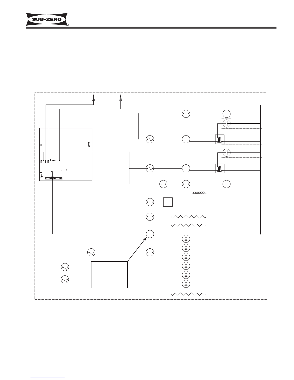
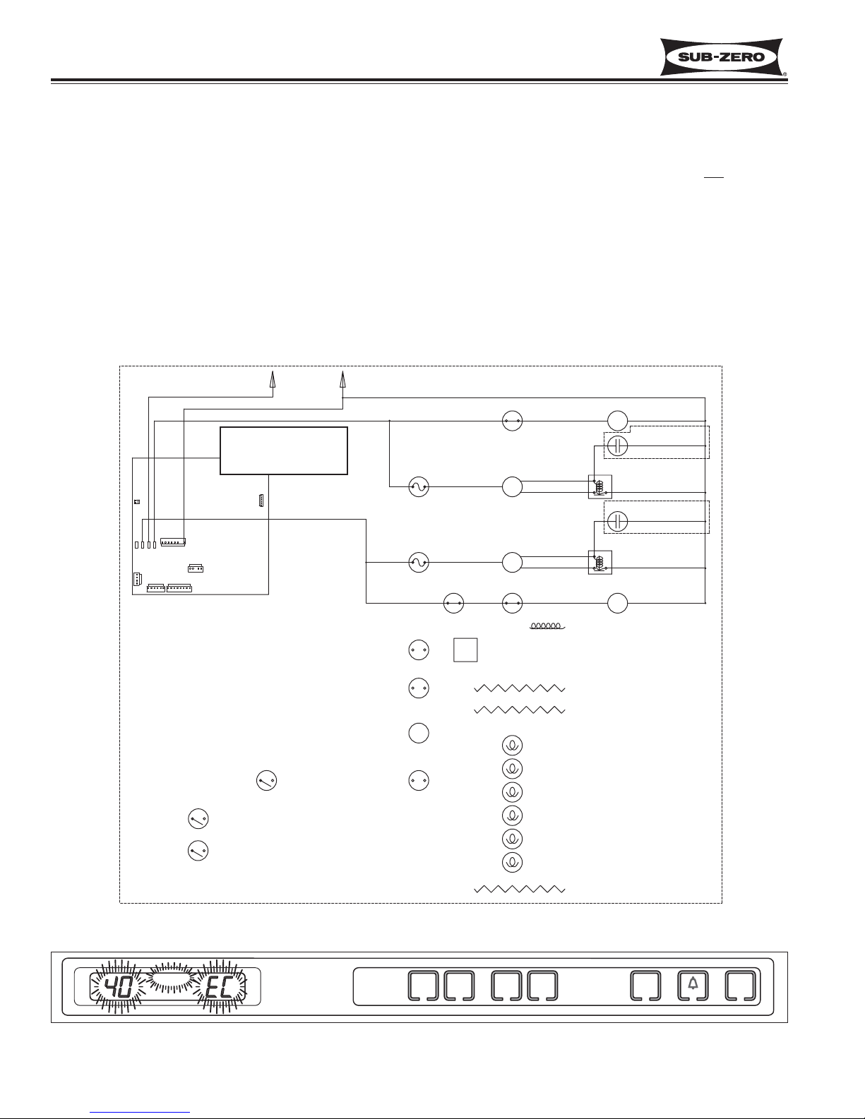
Figure 3-25. 700TC/I-3 Signal Trace Schematic (High Voltage) of Compressor Electrical System
Figure 3-26. “SERVICE”, “40” or “50” and “EC” Flashing = Several Excessive Compressor Run Periods
length of compressor
run time is monitored
by microprocessor.
Monitor Compressor Run Duration, Displays If Service is Needed
In all models except the 700TF/I-3, the microprocessor observes the changing state of the compressor relays to
determine the length of compressor run time (See Figure 3-25). If a compressor runs 100% (Fre = 6 hours / Ref = 4
hours), an error code is logged (EC 40 / EC 50, respectively), and defrost is initiated, but SERVICE will not flash.
If several 100% run periods occur, and the compartment temperature does not fall to at least the set point / low offset temperature average (and the door is not opened during the last run period), then SERVICE will flash along with
the error code (See Figure 3-26).
NOTE: To clear a flashing SERVICE and EC, the problem must be corrected, then switch the unit off then back on
and/or press the Bell ON/OFF key for 15 seconds. Failure to clear an error code will cause SERVICE to display
constant once Diagnostic Mode is initiated.
NOTE: If the unit is ever switched OFF then back ON, the compressor will not energize for at least 3 minutes. This
3 minute minimum OFF time is used to protect the compressor and its electricals.
HIGH VOLTAGE
115 VOLTS
J5
E2 E7 E10 E6
J3
60 CYCLES
L1
BLACK
WHITE
GRAY
J6
PURPLE
J7
J4
J1
J2
NEUT
WHITE
REFRIGERATOR
FAN SWITCH
REFRIGERATOR
COMPRESSOR
M
REFRIGERATOR
OVERLOAD
PROTECTOR
FREEZER
OVERLOAD
PROTECTOR
FREEZER
FAN
PURPLE RED
SWITCHES
FREEZER
COMPRESSOR
M
RED
REFRIGERATOR
FAN MOTOR
M
RUNNING
CAPACITOR
(WHEN USED)
STARTING
RELAY
RUNNING
CAPACITOR
(WHEN USED)
STARTING
RELAY
FREEZER
FAN MOTOR
M
SERVICE
FREEZER
M
WARMERCOLDER
WARMERCOLDER
REFRIGERATOR
ICE
ON/OFF
ON/OFF
UNIT
ON/OFF
Page 31

Integrated
Integrated
(700-
(700-
3
3
TTALL)
ALL)
Series
Series
Electronic Control System
3-17
#3758412 - Revision B - December, 2006
Figure 3-28. 700TC/I-3 Signal Trace Schematic (High Voltage) of Icemaker Electrical System
Figure 3-29. ICE & SERVICE Flashing = Solenoid Energized 15 sec., every 24 hrs., 5 consecutive times
115 Volts to water valve solenoid
is monitored by microprocessor.
If voltage supply lasts more than
15 seconds, power to icemaker
system is disabled.
Fill tube heater is energized
whenever icemaker system
is switched “ON” and ICE
appears on LCD
Monitor Icemaker System and Display If Service is Needed
The microprocessor observes the 115 Volts AC supplied to the icemaker water valve solenoid. If the solenoid is
energized for more than 15 seconds, power to the icemaker system is disabled for 24 hours (See Figure 3-28), and
an error code is logged (EC 30). If this happens five consecutive times, ICE and SERVICE on the LCD will flash
(See Figure 3-29), and the ICE ON/OFF key will be disabled.
NOTE: To clear the ICE and SERVICE error indicators, and reactivate the ICE ON/OFF key, the problem must be
corrected, then the unit must be switched OFF and back ON, and the Alarm key must be pressed for 15 seconds to
clear the Error Code.
NOTE: To allow ice to freeze fully and reduce effects of low water pressure, power to the icemaker system is interrupted for 45 minutes after each ice harvest. This can be bypassed for service purposes by switching the icemaker
system OFF, then back ON using the ICE ON/OFF key.
NOTE: When in Sabbath Mode, the icemaker system is disabled. Sabbath Mode will be covered later.
HIGH VOLTAGE
115 VOLTS
BLACK
WHITE
L1
60 CYCLES
NEUT
WHITE
M
J5
E2 E7 E10 E6
J3
J6
J7
J4
J1
J2
TAN
M
M
M
PINK
ICEMAKER
SWITCH
TAN
ICEMAKER
WATER
VALVE
M
WHITE/BLUE
2300-2900 OHMS
FILL TUBE
HEATER
ICE
SERVICE
FREEZER
WARMERCOLDER
WARMERCOLDER
REFRIGERATOR
ICE
ON/OFF
ON/OFF
UNIT
ON/OFF
Page 32

Electronic Control System
Integrated
Integrated
(700-
(700-
3
3
TTALL)
ALL)
Series
Series
3-18
#3758412 - Revision B - December, 2006
POSSIBLE ERROR INDICATORS
These pages contain diagrams illustrating what a customer may see on the LCD if there is a problem with the unit.
NOTE: To clear indicators and error codes, problem must be corrected then press Bell ON/OFF key for 15 seconds.
NOTE: For thermistor errors described below, thermistor can be tested by submersing it in a glass of ice water for 2
to 5 minutes, then check for 30,000 to 33,000 ohms.
• For Models 700TC/I-3 and 736TC/I-3, See Figures 3-30 through 3-36
• For Model 700TR-3 and 736TR-3, See Figures 3-37 through 3-42
• For Model 700TF/I-3, See Figures 3-43 through 3-47
Figure 3-34. 700TC/I-3 & 736TC/I-3
“ICE” & “SERVICE” Flashing = Valve Solenoid energized > fifteen (15) Seconds, Icemaker System Disabled
Figure 3-30. 700TC/I-3 & 736TC/I-3
“EE” at Left and “SERVICE” Flashing = Freezer Compartment Thermistor (or its Wiring) Fault
Figure 3-31. 700TC/I-3 & 736TC/I-3
“SERVICE” Flashing and “EE” at right = Refrig. Compartment Thermistor (or its wiring) Fault
Figure 3-32. 700TC/I-3 & 736TC/I-3
“SERVICE” Alone Flashing = Refrig. Evap. Thermistor (or its Wiring) Fault
Figure 3-33. 700TC/I-3 & 736TC/I-3
“40”, or “50” and “SERVICE” and “EC” Flashing = Excessive Compressor Run
Figure 3-35. 700TC/I-3 & 736TC/I-3
“SERVICE” Steady, not Flashing = Error Codes Observed in Diagnostic Mode, but not Cleared
Figure 3-36. 700TC/I-3 & 736TC/I-3
“ - - ” (Double Dashes) Displayed = Compartment Manually Disabled
SERVICE
FREEZER
WARMERCOLDER
WARMERCOLDER
REFRIGERATOR
ICE
ON/OFF
ON/OFF
SERVICE
FREEZER
WARMERCOLDER
WARMERCOLDER
REFRIGERATOR
ICE
ON/OFF
ON/OFF
SERVICE
FREEZER
WARMERCOLDER
WARMERCOLDER
REFRIGERATOR
ICE
ON/OFF
ON/OFF
SERVICE
FREEZER
WARMERCOLDER
WARMERCOLDER
REFRIGERATOR
ICE
ON/OFF
ON/OFF
UNIT
ON/OFF
UNIT
ON/OFF
UNIT
ON/OFF
UNIT
ON/OFF
SERVICE
ICE
SERVICE
FREEZER
WARMERCOLDER
FREEZER
WARMERCOLDER
FREEZER
WARMERCOLDER
WARMERCOLDER
WARMERCOLDER
WARMERCOLDER
REFRIGERATOR
REFRIGERATOR
REFRIGERATOR
ICE
ON/OFF
ICE
ON/OFF
ICE
ON/OFF
ON/OFF
ON/OFF
ON/OFF
UNIT
ON/OFF
UNIT
ON/OFF
UNIT
ON/OFF
Page 33

Integrated
Integrated
(700-
(700-
3
3
TTALL)
ALL)
Series
Series
Electronic Control System
3-19
#3758412 - Revision B - December, 2006
Figure 3-38. 700TR-3 & 736TR-3
“EE” at Right and “SERVICE” Flashing = Upper Compartment Thermistor (or its Wiring) Fault
Figure 3-39. 700TR-3 & 736TR-3
“SERVICE” Alone Flashing = Refrig. Evap. Thermistor (or its Wiring) Fault
Figure 3-37. 700TR-3 & 736TR-3
“EE” at Left and “SERVICE” Flashing = Lower Compartment Thermistor (or its Wiring) Fault
Figure 3-40. 700TR-3 & 736TR-3
“50”, “SERVICE” and “EC” Flashing = Excessive Compressor Run
Figure 3-41. 700TR-3 & 736TR-3
“SERVICE” Steady, not Flashing = Error Codes Observed in Diagnostic Mode, but not Cleared
Figure 3-42. 700TR & 736TR-3
“ - - ” (Double Dashes) Displayed = Compartment Manually Disabled
SERVICE
FREEZER
WARMERCOLDER
WARMERCOLDER
REFRIGERATOR
ICE
ON/OFF
ON/OFF
SERVICE
FREEZER
WARMERCOLDER
WARMERCOLDER
REFRIGERATOR
ICE
ON/OFF
ON/OFF
SERVICE
FREEZER
WARMERCOLDER
WARMERCOLDER
REFRIGERATOR
ICE
ON/OFF
ON/OFF
SERVICE
FREEZER
WARMERCOLDER
WARMERCOLDER
REFRIGERATOR
ICE
ON/OFF
ON/OFF
UNIT
ON/OFF
UNIT
ON/OFF
UNIT
ON/OFF
UNIT
ON/OFF
SERVICE
FREEZER
WARMERCOLDER
WARMERCOLDER
REFRIGERATOR
ICE
ON/OFF
ON/OFF
FREEZER
WARMERCOLDER
WARMERCOLDER
REFRIGERATOR
ICE
ON/OFF
ON/OFF
UNIT
ON/OFF
UNIT
ON/OFF
Page 34

Electronic Control System
Integrated
Integrated
(700-
(700-
3
3
TTALL)
ALL)
Series
Series
3-20
#3758412 - Revision B - December, 2006
Figure 3-44. 700TF/I-3
“ICE” & “SERVICE” Flashing = Valve Solenoid energized > fifteen (15) Seconds, Icemaker System Disabled
Figure 3-43. 700TF/I-3
“EE” at Left and “SERVICE” Flashing = Freezer Compartment Thermistor (or its Wiring) Fault
Figure 3-46. 700TF/I-3
“SERVICE” Steady, not Flashing = Error Codes Observed in Diagnostic Mode, but not Cleared
Figure 3-47. 700TF/I-3
“ - - ” (Double Dashes) Displayed = Compartment Manually Disabled
SERVICE
FREEZER
WARMERCOLDER
WARMERCOLDER
REFRIGERATOR
ICE
ON/OFF
ON/OFF
UNIT
ON/OFF
ICE
SERVICE
FREEZER
WARMERCOLDER
WARMERCOLDER
REFRIGERATOR
ICE
ON/OFF
ON/OFF
UNIT
ON/OFF
SERVICE
FREEZER
WARMERCOLDER
WARMERCOLDER
REFRIGERATOR
ICE
ON/OFF
ON/OFF
UNIT
ON/OFF
FREEZER
WARMERCOLDER
WARMERCOLDER
REFRIGERATOR
ICE
ON/OFF
ON/OFF
UNIT
ON/OFF
Page 35

Integrated
Integrated
(700-
(700-
3
3
TTALL)
ALL)
Series
Series
Electronic Control System
3-21
#3758412 - Revision B - December, 2006
TROUBLESHOOTING INPUT OPERATIONS
The following few pages explain troubleshooting input operations performed at the control panel. The input operations described are Diagnostic Mode, Manual Component Activation Mode and Temperature Log Recall.
Diagnostic Mode
Initiating Diagnostic Mode allows the Service Technician to observe real-time temperature readings from all thermistors without temperature averaging. If errors were detected, “Error Codes” will also display during diagnostic mode.
NOTE: The model 700TF/I-3 has only one compartment thermistor and one evaporator thermistor.
NOTE: Since Diagnostic Mode varies only slightly between the different models, a diagram of the 700TC/I-3 control
panel is used to illustrate Diagnostic Mode key strokes.
To initiate Diagnostic Mode, the unit must be ON, then press and hold either
COLDER key, and press the UNIT
ON/OFF key, then release both keys (See Figure 3-48). If no error codes are registered, the left display area will
show real-time temperature of the thermistor, the right display area will show the thermistor location code, and all
LCD indicators will illuminate. Pressing either
COLDER key or either WARMER key while in Diagnostic Mode will
toggle to the next or previous thermistor location, respectively. (See Figure 3-49, 3-50 and 3-51 and the Thermistor
Location Code Tables on the next page)
NOTE: If the COLDER and UNIT ON/OFF keys are pressed and held for 10 seconds, Manual Component
Activation Mode will be initiated (this is covered later in the section).
NOTE: Diagnostic Mode will end 20 seconds after the last key stroke.
Figure 3-48. Initiate Diagnostic Mode - Press and Hold Either
COLDER Key, Then the UNIT ON/OFF Key
(“F” Indicates Freezer Compartment)
Figure 3-49. Toggle Through Temperature Readings - Press Either COLDER Key
(“r” Indicates Refrigerator Compartment)
Figure 3-50. Toggle Through Temperature Readings - Press Either
COLDER Key
(“FE” Indicates Freezer Evaporator)
Figure 3-51. Toggle Through Temperature Readings - Press Either
COLDER Key
(“rE” Indicates Refrigerator Evaporator)
ICE
SERVICE
OFF
FREEZER
WARMERCOLDER
WARMERCOLDER
REFRIGERATOR
ICE
ON/OFF
ON/OFF
UNIT
ON/OFF
ICE
SERVICE
OFF
FREEZER
WARMERCOLDER
WARMERCOLDER
REFRIGERATOR
ICE
ON/OFF
ON/OFF
UNIT
ON/OFF
SERVICE
ICE
OFF
SERVICE
ICE
OFF
FREEZER
WARMERCOLDER
WARMERCOLDER
FREEZER
WARMERCOLDER
WARMERCOLDER
REFRIGERATOR
ICE
ON/OFF
ON/OFF
UNIT
ON/OFF
REFRIGERATOR
ICE
ON/OFF
ON/OFF
UNIT
ON/OFF
Page 36

Electronic Control System
Integrated
Integrated
(700-
(700-
3
3
TTALL)
ALL)
Series
Series
3-22
#3758412 - Revision B - December, 2006
Figure 3-52. “EE” Observed in Diagnostic Mode = Thermistor Fault in Location Indicated by Code
Figure 3-53. “Sr” Observed While in Diagnostic Mode = Unit is in Showroom Mode
Diagnostic Mode Indicators
If “EE” is observed in the left display area during Diagnostic Mode, the thermistor in that location is open or shorted,
or there is a break in that thermistor’s wiring (See Figure 3-52).
If “Sr” is observed in the left display area when Diagnostic Mode is initiated, the unit is in Showroom Mode, which
was explained earlier in this section (See Figure 3-53).
If “EC” is observed in the right display area during Diagnostic Mode, the numbers at left are “Error Codes” (See
Figure 3-55 and the Error Code Table on next page). Error Codes indicate problems registered by specific components. If error codes are registered, they will appear before temperature readings and can be toggled through with
the temperature readings as described on the previous page.
Figure 3-55. “EC” Observed While in Diagnostic Mode = Error Code (See Table on Following Page)
700TC/I-3 & 736TC/I-3
THERMISTOR LOCATION CODE
Freezer Compartment F
Refrigerator Compartment r
Freezer Evaporator FE
Refrigerator Evaporator rE
700TR-3 & 736TR-3
THERMISTOR LOCATION CODE
Lower Compartment L
Upper Compartment U
Lower Evaporator LE
Upper Evaporator UE
700TF/I-3
THERMISTOR LOCATION CODE
Freezer Compartment F
Freezer Evaporator FE
ICE
SERVICE
OFF
FREEZER
WARMERCOLDER
WARMERCOLDER
REFRIGERATOR
ICE
ON/OFF
ON/OFF
UNIT
ON/OFF
ICE
SERVICE
OFF
FREEZER
WARMERCOLDER
WARMERCOLDER
REFRIGERATOR
ICE
ON/OFF
ON/OFF
UNIT
ON/OFF
ICE
SERVICE
OFF
FREEZER
WARMERCOLDER
WARMERCOLDER
REFRIGERATOR
ICE
ON/OFF
ON/OFF
UNIT
ON/OFF
Page 37

Integrated
Integrated
(700-
(700-
3
3
TTALL)
ALL)
Series
Series
Electronic Control System
3-23
#3758412 - Revision B - December, 2006
Error Code Table
CODE INDICATION
05 Refrig. cabinet thermistor read open or shorted for 10+ seconds, or repeatedly read erratic temp’s
06 Refrig. evaporator thermistor read open or shorted for 10+ seconds, or repeatedly read erratic temp’s
07 Freezer cabinet thermistor read open or shorted for 10+ seconds, or repeatedly read erratic temp’s
08 Freezer evaporator thermistor read open or shorted for 10+ seconds, or repeatedly read erratic temp’s
20 Defrost under-heat with no voltage feedback through Gray/White wire at defrost start
21 Defrost overheat
22 No voltage feedback through Gray/White wire at defrost start
23 Defrost overheat with no voltage feedback through Gray/White wire at defrost start
24 Defrost Under-heat
30 Excessive Icemaker Water Valve Solenoid Activation (Exceeded 15 Seconds)
40 Excessive Freezer Compressor Run
50 Excessive Refrigerator Compressor Run
NOTE: The table above will be updated through addendums when subsequent software and electrical changes
occur and more error codes are added.
Clearing Error Codes
If error codes are observed during Diagnostic Mode, a non-flashing
SERVICE annunciator will appear on the LCD
when Diagnostic Mode ends, indicating error codes are still registered (See Figure 3-56). To clear a non-flashing
SERVICE annunciator and the error codes, the problem must be corrected and the unit must be ON. Then, the Bell
ON/OFF key must be pressed and held for fifteen (15) seconds. The control will emit a short “beep” when the SERVICE annunciator and error codes are cleared. (See Figure 3-57)
Figure 3-57. Clear Non-flashing SERVICE Annunciator - Press & Hold Bell ON/OFF Key for 15 Seconds
Figure 3-56. Non-flashing SERVICE Annunciator after Diagnostic Mode = Error Codes were Registered
Press and hold for 15 seconds
BBEEEEPP!!
SERVICE
FREEZER
WARMERCOLDER
WARMERCOLDER
REFRIGERATOR
ICE
ON/OFF
ON/OFF
UNIT
ON/OFF
FREEZER
WARMERCOLDER
WARMERCOLDER
REFRIGERATOR
ICE
ON/OFF
ON/OFF
UNIT
ON/OFF
Page 38

Electronic Control System
Integrated
Integrated
(700-
(700-
3
3
TTALL)
ALL)
Series
Series
3-24
#3758412 - Revision B - December, 2006
Figure 3-58. Initiate Manual Component Activation Mode -
Press and Hold Desired COLDER Key and UNIT ON/OFF Key for 10 Seconds
Manual Component Activation Mode
Manual Component Activation Mode allows a Service Technician to energize a cooling system for five minutes.
When activated, the chosen zone’s compressor and evaporator fan are energized along with the condenser fan.
While in Component Activation Mode, the evaporator temperatures for that zone are displayed on the LCD. This
also allows the Service Technician to check for proper voltage readings at the activated components without having
to wait for the compartment to call for cooling.
To initiate Manual Component Activation Mode, the unit must be ON. With the unit ON, press and hold the desired
zone COLDER key and the UNIT ON/OFF key for ten seconds (See Figure 3-58). The evaporator temperature for
that compartment will be displayed in the left display area of the LCD and the right display area will show the thermistor location.
NOTE: If the COLDER and UNIT ON/OFF keys are pressed and held for less then 10 seconds, Diagnostic Mode
will be initiated.
NOTE: It is possible to toggle through the the other temperature readings as in Diagnostic Mode, but in this case
the temperature readings will last for five minutes rather than twenty seconds.
NOTE: The compressor overload could prevent the compressor from energizing.
NOTE: Manual Component Activation Mode will end five minutes after it is initiated. It is possible to end this five
minute run time and return to normal operation by switching the unit OFF then back ON. If this is done, note that
the electronic control will observe a three minute minimum compressor OFF time when the unit is switched back
ON. This is to protect the compressor and its electricals.
Press and hold for 10 seconds
ICE
SERVICE
OFF
FREEZER
WARMERCOLDER
WARMERCOLDER
REFRIGERATOR
ICE
ON/OFF
ON/OFF
UNIT
ON/OFF
Page 39

Integrated
Integrated
(700-
(700-
3
3
TTALL)
ALL)
Series
Series
Electronic Control System
3-25
#3758412 - Revision B - December, 2006
Temperature Log Recall Mode
The electronic control system is equipped with a temperature history data storage system. This system logs/stores
the average temperature of each individual thermistor every two hours, along with any event indicators (explained
later in this section), that may have occurred. These two-hour periods are referred to as “indexes”. Up to 168
indexes can be stored for each compartment, making it possible to observe the preceding fourteen days of the unit’s
temperature history (each index equals 2 hour temperature average; 2 hours X 168 indexes = 14 days). After 168
indexes are stored, each new index will bump the oldest index. Index number “1” being the most recent two-hour
temperature average and index number “168” being the oldest. Accessing this temperature history data so it can be
viewed on the LCD is accomplished by initiating Temperature Log Recall Mode.
There are two ways to initiate Temperature Log Recall Mode. One allows viewing of compartment temperature history only (see below), the other allows viewing of compartment temperature history and evaporator temperature history (see following page).
Initiate Temperature Log Recall Mode To View Compartment Temperature History Only - Begin with the unit
ON. Now, press and hold the desired compartment WARMER key, then press the UNIT ON/OFF key, then release
both keys (See Figure 3-59). The left display area on the LCD will show average compartment thermistor temperature and in the right display area will be the index number. The first index number will be “1”, indicating the most
recent two-hour temperature average. The right display area will also flash the thermistor location code at 3 second
intervals (See Figure 3-60).
Figure 3-59. Initiate Temperature Log Recall Mode To View Compartment Temperature History Only -
Press and Hold Desired
WARMER Key, Then Press UNIT ON/OFF Key
Figure 3-60. Thermistor Location Code Flashes Every Three Seconds
Figure 3-61. Toggle Up Through Indexes - Press WARMER Key in Consecutive Key Strokes
Figure 3-62. Toggle Down Through Indexes - Press COLDER Key in Consecutive Key Strokes
To toggle up through the indexes (from 1 to 168), press the same WARMER key in multiple key strokes (See Figure
3-61). To toggle down through the indexes (from 168 to 1), press the corresponding COLDER key in multiple key
strokes (See Figure 3-62).
FREEZER
WARMERCOLDER
WARMERCOLDER
REFRIGERATOR
ICE
ON/OFF
ON/OFF
UNIT
ON/OFF
FREEZER
WARMERCOLDER
WARMERCOLDER
REFRIGERATOR
ICE
ON/OFF
ON/OFF
UNIT
ON/OFF
FREEZER
WARMERCOLDER
WARMERCOLDER
REFRIGERATOR
ICE
ON/OFF
ON/OFF
UNIT
ON/OFF
FREEZER
WARMERCOLDER
WARMERCOLDER
REFRIGERATOR
ICE
ON/OFF
ON/OFF
UNIT
ON/OFF
Page 40

Electronic Control System
Integrated
Integrated
(700-
(700-
3
3
TTALL)
ALL)
Series
Series
3-26
#3758412 - Revision B - December, 2006
Figure 3-65. Initiate Temperature Log Recall Mode To View Temperature History -
Press and Hold Desired
WARMER Key and UNIT ON/OFF Key
UNIT
ICE
REFRIGERATOR
ON/OFF
ON/OFF
ON/OFF
WARMERCOLDER
FREEZER
WARMERCOLDER
Figure 3-63. Initiate Diagnostic Mode - Press and Hold Either COLDER Key, then the UNIT ON/OFF Key
Figure 3-64. Toggle Through Temperature Readings - Press Either COLDER Key or Either WARMER Key
Until Desired Thermistor Temperature is Displayed
Initiate Temperature Log Recall Mode To View Compartment and Evaporator Temperature History - Begin
with the unit ON and in Diagnostic Mode (See Figure 3-63). While in Diagnostic Mode, toggle through the readings
until the desired thermistor temperature is displayed on the LCD (See Figure 3-64). Now, press the WARMER key
for that compartment and the UNIT ON/OFF key simultaneously (See Figure 3-65). The left display area on the LCD
will show average thermistor temperature and in the right display area will be the index number “1” indicating the
most recent 2-hour temperature average (See Figure 3-65). The right display area will also flash the thermistor
location code at three second intervals (See Figure 3-66).
To toggle up
through the indexes (from 1 to 168), press the same WARMER key in multiple key strokes (See Figure
3-67). To toggle down through the indexes (from 168 to 1), press the corresponding COLDER key in multiple key
strokes (See Figure 3-68).
Figure 3-66. Thermistor Location Code Flashes Every Three Seconds
Figure 3-67. Toggle Up Through Indexes - Press WARMER Key in Consecutive Key Strokes
Figure 3-68. Toggle Down Through Indexes - Press COLDER Key in Consecutive Key Strokes
ICE
SERVICE
OFF
FREEZER
WARMERCOLDER
WARMERCOLDER
REFRIGERATOR
ICE
ON/OFF
ON/OFF
UNIT
ON/OFF
ICE
SERVICE
OFF
FREEZER
WARMERCOLDER
WARMERCOLDER
REFRIGERATOR
ICE
ON/OFF
ON/OFF
UNIT
ON/OFF
FREEZER
WARMERCOLDER
WARMERCOLDER
REFRIGERATOR
ICE
ON/OFF
ON/OFF
UNIT
ON/OFF
FREEZER
FREEZER
ICE
ON/OFF
ICE
ON/OFF
ON/OFF
ON/OFF
WARMERCOLDER
WARMERCOLDER
WARMERCOLDER
WARMERCOLDER
REFRIGERATOR
REFRIGERATOR
UNIT
ON/OFF
UNIT
ON/OFF
Page 41

Integrated
Integrated
(700-
(700-
3
3
TTALL)
ALL)
Series
Series
Electronic Control System
3-27
#3758412 - Revision B - December, 2006
Figure 3-70. SERVICE Annunciator Illuminates - Indicates Unit was switched OFF During that Index Period
by Pressing UNIT ON/OFF Key
Figure 3-71. Bell Illuminates - Indicates Power Failure / Interruption During that Index Period
Figure 3-72. Double Dashes ( - - ) Displayed Instead of Temperature for Several Consecutive Index Periods -
Indicates Bad EEPROM on Control Board. Board Must be Replaced
NOTE: Double dashes will also be observed when in Manual Zone Disable Mode. Only when double dashes are
observed in Temperature Log Recall Mode for several consecutive indexes
should the control board be replaced.
NOTE: If Manual Zone Disable Mode has been activated during any of the 168 indexes, average temperatures will
continue to be logged. No event indicator will appear with these temperatures.
NOTE: If the unit was in Showroom Mode during any of the 168 indexes, average temperatures will continue to be
logged. No event indicator will appear with these temperatures.
NOTE: If the unit was switched OFF by pressing the UNIT ON/OFF key during any of the 168 indexes and there
was still 115V AC supplied to the control board, the average temperatures will continue to be logged. This means
temperatures would be expected to rise and the SERVICE annunciator would be present in all indexes in which the
unit was OFF.
NOTE: Temperature Log Recall Mode will end 20 seconds after the last key stroke.
Possible Temperature Log Recall Mode Event Indicators
The diagrams below illustrate possible event indicators that may be observed while in Temperature Log Recall
Mode. (See Figures 3-69 through 3-72)
Figure 3-69. “bl” Indicates Index is “blank
” - No Temperature has Been Logged Yet
(Only possible within first 14 days of unit operation, or after new control board is installed during service)
FREEZER
WARMERCOLDER
WARMERCOLDER
REFRIGERATOR
ICE
ON/OFF
ON/OFF
UNIT
ON/OFF
SERVICE
FREEZER
WARMERCOLDER
WARMERCOLDER
REFRIGERATOR
ICE
ON/OFF
ON/OFF
UNIT
ON/OFF
FREEZER
WARMERCOLDER
WARMERCOLDER
REFRIGERATOR
ICE
ON/OFF
ON/OFF
UNIT
ON/OFF
FREEZER
WARMERCOLDER
WARMERCOLDER
REFRIGERATOR
ICE
ON/OFF
ON/OFF
UNIT
ON/OFF
Page 42

Electronic Control System
Integrated
Integrated
(700-
(700-
3
3
TTALL)
ALL)
Series
Series
3-28
#3758412 - Revision B - December, 2006
Index= Hours Past
1 = 2 Hrs
2=4 Hrs
3=6 Hrs
4 = 8Hrs
5 = 10Hrs
6 = 12 Hrs
7 = 14 Hrs
8 = 16 Hrs
9 = 18 Hrs
10 = 20 Hrs
11 = 22 Hrs
12 = 24 Hrs (1 Day)
13 = 26 Hrs
14 = 28 Hrs
15 = 30 Hrs
16 = 32 Hrs
17 = 34 Hrs
18 = 36 Hrs
19 = 38 Hrs
20 = 40 Hrs
21 = 42 Hrs
22 = 44 Hrs
23 = 46 Hrs
24 = 48 Hrs (2 Days)
25 = 50 Hrs
26 = 52 Hrs
27 = 54 Hrs
28 = 56 Hrs
29 = 58 Hrs
30 = 60 Hrs
31 = 62 Hrs
32 = 64 Hrs
33 = 66 Hrs
34 = 68 Hrs
35 = 70 Hrs
36 = 72 Hrs (3 Days)
37 = 74 Hrs
38 = 76 Hrs
39 = 78 Hrs
40 = 80 Hrs
41 = 82 Hrs
42 = 84 Hrs
Index= Hours Past
43 = 86 Hrs
44 = 88 Hrs
45 = 90 Hrs
46 = 92 Hrs
47 = 94 Hrs
48 = 96 Hrs (4 Days)
49 = 98 Hrs
50 = 100 Hrs
51 = 102 Hrs
52 = 104 Hrs
53 = 106 Hrs
54 = 108 Hrs
55 = 110 Hrs
56 = 112 Hrs
57 = 114 Hrs
58 = 116 Hrs
59 = 118 Hrs
60 = 120 Hrs (5 Days)
61 = 122 Hrs
62 = 124 Hrs
63 = 126 Hrs
64 = 128 Hrs
65 = 130 Hrs
66 = 132 Hrs
67 = 134 Hrs
68 = 136 Hrs
69 = 138 Hrs
70 = 140 Hrs
71 = 142 Hrs
72 = 144 Hrs (6 Days)
73 = 146 Hrs
74 = 148 Hrs
75 = 150 Hrs
76 = 152 Hrs
77 = 154 Hrs
78 = 156 Hrs
79 = 158 Hrs
80 = 160 Hrs
81 = 162 Hrs
82 = 164 Hrs
83 = 166 Hrs
84 = 168 Hrs (7 Days)
Index= Hours Past
85 = 170 Hrs
86 = 172 Hrs
87 = 174 Hrs
88 = 176 Hrs
89 = 178 Hrs
90 = 180 Hrs
91 = 182 Hrs
92 = 184 Hrs
93 = 186 Hrs
94 = 188 Hrs
95 = 190 Hrs
96 = 192 Hrs (8 Days)
97 = 194 Hrs
98 = 196 Hrs
99 = 198 Hrs
100 = 200 Hrs
101 = 202 Hrs
102 = 204 Hrs
103 = 206 Hrs
104 = 208 Hrs
105 = 210 Hrs
106 = 202 Hrs
107 = 214 Hrs
108 = 216 Hrs (9 Days)
109 = 218 Hrs
110 = 220 Hrs
111 = 222 Hrs
112 = 224 Hrs
113 = 226 Hrs
114 = 228 Hrs
115 = 230 Hrs
116 = 232 Hrs
117 = 234 Hrs
118 = 236 Hrs
119 = 238 hrs
120 = 240 Hrs (10 Days)
121 = 242 Hrs
122 = 244 Hrs
123 = 246 Hrs
124 = 248 Hrs
125 = 250 Hrs
126 = 252 Hrs
Index= Hours Past
127 = 254 Hrs
128 = 256 Hrs
129 = 258 Hrs
130 = 260 Hrs
131 = 262 Hrs
132 = 264 Hrs (11 Days)
133 = 266 Hrs
134 = 268 Hrs
135 = 270 hrs
136 = 272 Hrs
137 = 274 Hrs
138 = 276 Hrs
139 = 278 Hrs
140 = 280 Hrs
141 = 282 Hrs
142 = 284 Hrs
143 = 286 Hrs
144 = 288 Hrs (12 Days)
145 = 290 Hrs
146 = 292 Hrs
147 = 294 Hrs
148 = 296 Hrs
149 = 298 Hrs
150 = 300 Hrs
151 = 302 Hrs
152 = 304 Hrs
153 = 306 Hrs
154 = 308 Hrs
155 = 310 Hrs
156 = 312 Hrs (13 Days)
157 = 314 Hrs
158 = 316 Hrs
159 = 318 Hrs
160 = 320 Hrs
161 = 322 Hrs
162 = 324 Hrs
163 = 326 hrs
164 = 328 Hrs
165 = 330 Hrs
166 = 332 Hrs
167 = 334 Hrs
168 = 336 Hrs (14 Days)
Temperature Log Index Chart
NOTE : The chart below applies to the hours in which the control has power. Temperature history data will only be
stored when the control has 115V AC supplied to it. If power to the unit is interrupted, the average temperatures for
that time period are stored with the event indicator. The temperature history data is stored in a non-volatile memory,
so the data is not erased by a power failure, but actual time passage during the power failure will not be shown.
TEMPERATURE LOG INDEX CHART
Page 43

Integrated
Integrated
(700-
(700-
3
3
TTALL)
ALL)
Series
Series
Sealed System Information
4-1
#3758412 - Revision B - December, 2006
SECTION 4
SEALED SYSTEM
INFORMATION
Page 44

Sealed System Information
Integrated
Integrated
(700-
(700-
3
3
TTALL)
ALL)
Series
Series
4-2
#3758412 - Revision B - December, 2006
HFC-134a REFRIGERANT SERVICE INFORMATION
The 700-3 Series sealed systems contain HFC-134a refrigerant. This section provides some general rules for working with 134a, and explains procedures to be followed while servicing the sealed system. This is followed by diagrams which illustrate sealed system operation, then model-specific refrigerant flow diagrams.
134a refrigerant requires Synthetic Ester oil in the compressor, and does not tolerate contamination from
other refrigerants, moisture, petroleum-based lubricants, silicone lubricants, cleaning compounds, rust
inhibitors, leak detection dyes, or any other type of additive.
General Rules for Working with 134a Refrigerant
• Use equipment dedicated to 134a sealed system service only.
• Use only 134a refrigerant for back-flushing and sweep charging.
• Always replace the filter-drier when servicing the sealed system.
• The filter-drier must be cut from the sealed system. Never un-braze the drier as the heat will drive moisture
back into the sealed system.
• Do not leave sealed system nor replacement compressor open to the atmosphere for more than 10 minutes.
• When the rubber plugs are pulled from the service compressor, a release of pressure should be heard. If no
release of pressure is heard, do not use the compressor.
• Use ONLY virgin 134a refrigerant when recharging the sealed system.
Page 45

Integrated
Integrated
(700-
(700-
3
3
TTALL)
ALL)
Series
Series
Sealed System Information
4-3
#3758412 - Revision B - December, 2006
SEALED SYSTEM REPAIR PROCEDURES
Service Procedures
a. Capture refrigerant
b. Replace Compressor
c. Replace filter-drier
d. Evacuate or sweep charge system
e. Recharge system with Virgin 134a refrigerant.
NOTE: To check for a non-operating compressor, a hard start kit can be used.
a. Capture refrigerant.
b. Repair leak.
c. Replace filter-drier.
d. Evacuate or sweep charge system.
e. Recharge system with Virgin 134a refrigerant.
a. Capture refrigerant.
b. Repair leak (if at solder joint) or replace part.
c. Back flush high side of sealed system.
d. If all refrigerant has escaped & system is in vacuum, replace compressor.
e. Replace filter-drier.
f. Evacuate or sweep charge system.
g. Recharge system with Virgin 134a refrigerant.
a. Capture refrigerant.
b. Repair leak (if at solder joint) or replace part.
c. Back flush high side of sealed system.
d. Replace compressor.
e. Replace filter-drier.
f. Replace heat exchanger if cap tube is clogged.
g. Install a low side drier on suction line.
h. Evacuate or sweep charge sealed system.
i. Recharge with Virgin 134a refrigerant.
a. Capture refrigerant.
b. Locate and remove restriction or locate and replace part.
c. Back flush high side of sealed system.
d. Replace filter-drier.
e. Evacuate or sweep charge system.
f Recharge system with Virgin 134a refrigerant.
a. Capture refrigerant.
b. Replace filter-drier.
c. Evacuate or sweep charge system.
d. Recharge system with Virgin 134a refrigerant.
.
Problem
Non-Operating, Inefficient,
Noisy Compressor
High Side leak
Low Side Leak
Contaminated Sealed System
Examples:
> Burned out compressor
> Excessive moisture from
leak in condensate loop or in
low side
> Plugged capillary tube
Restriction
NOTE: If restriction is due to
sealed system being contaminated, see Contaminated
Sealed System above.
Overcharge
Page 46

Sealed System Information
Integrated
Integrated
(700-
(700-
3
3
TTALL)
ALL)
Series
Series
4-4
#3758412 - Revision B - December, 2006
Figure 4-2. Condenser & Heater Loop
SEALED SYSTEM OPERATION
The six diagrams on these pages illustrate a basic sealed
system. The components are listed in order of refrigerant
flow, with an explanation of their fundamental role as part
of a sealed system. NOTE: These illustrations do not
represent any specific 700-2 sealed system.
Compressor (Figure 4-1)
The compressor creates a high side and low side pressure
difference in the sealed system by compressing the refrigerant gas, thus raising the pressure and temperature. The
compressor pushes this high-pressure/high-heat gas to the
condenser.
Condenser (Figure 4-2)
The high-pressure/high-heat gas travels through the condenser, where the heat is dissipated by cooler air being
drawn over the condenser tubing by the condenser fan.
This changes the gas into a high-pressure/warm liquid that
is then routed through the door gasket seat heater loop to
prevent sweating. After traveling through the heater loop,
the high-pressure/warm liquid enters the high-side filterdrier.
Filter-Drier (Figure 4-3)
The high-pressure/warm liquid travels through the highside filter-drier, which removes moisture from the refrigerant before it enters the capillary tube.
Figure 4-3. Filter-Drier
Figure 4-1. Compressor
1
3
2
COMPRESSOR
HEATER LOOP
CONDENSER
FILTER-DRIER
Page 47

Integrated
Integrated
(700-
(700-
3
3
TTALL)
ALL)
Series
Series
Sealed System Information
4-5
#3758412 - Revision B - December, 2006
Figure 4-5. Evaporator
Capillary Tube (& Heat Exchanger) (Figure 4-4)
The warm liquid refrigerant travels through the long skinny
capillary tube which is soldered to the suction line. (These
two tubes soldered together create the heat exchanger.)
As the warm liquid refrigerant travels through the capillary
tube it gives up heat to the cool refrigerant gas traveling
through the suction line and the pressure drops, so it is a
low-pressure/cool liquid before it enters the evaporator.
Evaporator (Figure 4-5)
As the low-pressure/cool liquid refrigerant enters the evaporator, it vaporizes. This is caused by a dramatic pressure
change which occurs when the refrigerant enters the larger diameter evaporator tubing from the smaller diameter
capillary tubing. This vapor travels through the evaporator
absorbing heat from the compartment, gradually converting it to a cool gas. This cool gas then enters the suction
line.
Suction Line (& Heat Exchanger) (Figure 4-6)
The cool gas travels through the suction line which is soldered to the capillary tube. (As mentioned earlier, these
two tubes soldered together create the heat exchanger.)
As this cool refrigerant gas travels through the suction line
it absorbs heat from the warm liquid refrigerant traveling
through the capillary tube, making it a luke warm gas. The
lukewarm refrigerant gas then returns to the compressor
where the process begins again.
Figure 4-6. Suction Line & Heat Exchanger
Figure 4-4. Capillary Tube (& Heat Exchanger)
5
HEAT EXCHANGER
4
6
CAPILLARY TUBE
EVAPORATOR
HEAT EXCHANGER
SUCTION LINE
Page 48

Sealed System Information
Integrated
Integrated
(700-
(700-
3
3
TTALL)
ALL)
Series
Series
4-6
#3758412 - Revision B - December, 2006
SEALED SYSTEM REFRIGERANT FLOW DIAGRAMS
Figure 4-7. Models 700TC/I-3 and 736TC/I-3 Refrigerant Flow
= REFRIGERATOR SEALED SYSTEM
= FREEZER SEALED SYSTEM
FRAME HEATER (HOT GAS)
REFRIGERATOR HEAT-EXCHANGER
FREEZER HEAT-EXCHANGER
REFRIGERATOR COMPRESSOR
FREEZER COMPRESSOR
REFRIGERATOR EVAPORATOR
FREEZER EVAPORATOR
FREEZER FILTER-DRIER
REFRIGERATOR FILTER-DRIER
CONDENSER
(FRONT - FREEZER)
(BACK - REFRIGERATOR)
Page 49

Integrated
Integrated
(700-
(700-
3
3
TTALL)
ALL)
Series
Series
Sealed System Information
4-7
#3758412 - Revision B - December, 2006
Figure 4-8. Model 700TR-3 and 736TR-3 Refrigerant Flow
Figure 4-9. Model 700TF/I-3 Refrigerant Flow
= UPPER REFRIGERATOR SEALED SYSTEM
= LOWER REFRIGERATOR SEALED SYSTEM
REFRIGERATOR HEAT-EXCHANGER
(UPPER)
FRAME HEATER (HOT GAS)
REFRIGERATOR EVAPORATOR
(UPPER)
REFRIGRATOR HEAT-EXCHANGER
(LOWER)
REFRIGERATOR COMPRESSOR
(UPPER)
REFRIGERATOR COMPRESSOR
(LOWER)
= FREEZER SEALED SYSTEM
REFRIGERATOR EVAPORATOR
(LOWER)
REFRIGERATOR FILTER-DRIER (UPR)
REFRIGERATOR FILTER-DRIER (LWR)
CONDENSER
(FRONT - REFRIGERATOR, LOWER)
(BACK - REFRIGERATOR, UPPER)
FRAME HEATER (HOT GAS)
HEAT-EXCHANGER
COMPRESSOR
EVAPORATOR
FILTER-DRIER
CONDENSER
Page 50

Sealed System Information
Integrated
Integrated
(700-
(700-
3
3
TTALL)
ALL)
Series
Series
4-8
#3758412 - Revision B - December, 2006
Page 51

Integrated
Integrated
(700-
(700-
3
3
TTALL)
ALL)
Series
Series
Airflow & Fan Blade Spacing
5-1
#3758412 - Revision B - December, 2006
SECTION 5
AIR FLOW &
FAN BLADE SPACING
Page 52

Airflow & Fan Blade Spacing
Integrated
Integrated
(700-
(700-
3
3
TTALL)
ALL)
Series
Series
5-2
#3758412 - Revision B - December, 2006
Figure 5-1. 700TC/I-3 and 736TC/I-3 Air Flow and Fan Blade Spacing
700TC/I-3:
736TC/I-3:
1” ± 3/32”
(25.4 mm ± 0.8 mm)
7/8” ± 1/16”
(22.2 mm ± 1.6 mm)
7/8” ± 1/16”
(22.2 mm ± 1.6 mm)
UPPER FAN MOTOR
Bracket
Blade
Clamp
Away From
Motor
LOWER FAN MOTOR
Bracket
Clamp
Away From
Motor
Blade
Page 53

Integrated
Integrated
(700-
(700-
3
3
TTALL)
ALL)
Series
Series
Airflow & Fan Blade Spacing
5-3
#3758412 - Revision B - December, 2006
Figure 5-2. 700TR-3 and 736TR-3 Air Flow and Fan Blade Spacing
1” ± 3/32”
(25.4 mm ± 0.8 mm)
Figure 5-3. 700TF/I-3 Air Flow and Fan Blade Spacing
1” ± 3/32”
(25.4 mm ± 0.8 mm)
700TR-3:
736TR-3:
1” ± 3/32”
(25.4 mm ± 0.8 mm)
7/8” ± 1/16”
(22.2 mm ± 1.6 mm)
UPPER FAN MOTOR
Bracket
Blade
Clamp
Away From
Motor
LOWER FAN MOTOR
FAN MOTOR
Blade
Bracket
Clamp
Away From
Motor
Blade
Bracket
Clamp
Away From
Motor
Page 54

Airflow & Fan Blade Spacing
Integrated
Integrated
(700-
(700-
3
3
TTALL)
ALL)
Series
Series
5-4
#3758412 - Revision B - December, 2006
Page 55

Integrated
Integrated
(700-
(700-
3
3
TTALL)
ALL)
Series
Series
Icemaker Information
6-1
#3758412 - Revision B - December, 2006
SECTION 6
ICEMAKER
INFORMATION
Page 56

Icemaker Information
Integrated
Integrated
(700-
(700-
3
3
TTALL)
ALL)
Series
Series
6-2
#3758412 - Revision B - December, 2006
ICEMAKER SYSTEM INFORMATION
The model 700TFI-3 utilizes a Modular ® icemaker, while the models 700TCI-3 and 736TCI-3 utilize either a
MidSouth ® Icemaker, or Japan-Servo ® Icemaker.
This section is divided in two parts
ICEMAKER MODEL
PAGES
Modular Icemaker Information (Model 700TFI-3 Only) ........................................................................ 6-3 through 6-5
MidSouth and Japan-Servo Icemaker information (Models 700TCI-3 and 736TCI Only) ................. 6-6 through 6-13
Additional Icemaker System Information
• The ICE ON/OFF key at the control panel activates the icemaker system. If “ICE” is not displayed on the LCD, the
icemaker system is OFF.
• To allow ice to freeze fully and reduce effects of low water pressure, the electronic control system disables the ice-
maker system for 45 minutes after each ice harvest. To bypass the 45 minute dwell, press the ICE key to switch
the ice making system OFF, then press the ICE key again to cycle the ice making system back ON.
• The ice bucket activates a switch when in place. If the ice bucket is not in proper position, ice production will stop.
• The icemaker shut-off arm must be in the “down / on” position for the icemaker to operate.
• The icemaker relay on the control board also controls the fill tube heater and water valve.
Page 57

Integrated
Integrated
(700-
(700-
3
3
TTALL)
ALL)
Series
Series
Icemaker Information
6-3
#3758412 - Revision B - December, 2006
Figure 6-1. Modular Icemaker Electrical Schematic
What Happens During Modular Icemaker Ejector Blade Rotation (700TFI-3 ONLY)
Figure 6-2 represents a view of the ejector blade from the front (or module side) of the icemaker. This diagram indicates what happens during the rotation of the ejector blade and will assist the Service Technician in diagnosing icemaker problems.
Figure 6-2. Ejector Blade Rotation Diagram
MODULAR ICEMAKER OPERATION (700TFI-3 ONLY)
When the icemaker thermostat has sensed temperatures of 17°F, the thermostat closes. At this time, the current
now has a path through the thermostat to the motor. The motor is linked with the drive gear. From the module,
there are copper contacts that ride on copper strips on the backside of the drive gear. (See Figure 6-1) As the drive
gear rotates, these contacts from the module will make or break a circuit (track) to the copper strips to generate the
icemaker cycle.
Power
(Pink)
Water Valve
Tan
Neutral
(White)
TP
Green
TP
Shut-Off
Switch
T
4400 Ω Timer
Mtr.
TP
NL
On (Dn)
Off (Up)
TP
Contact C
(Holding Switch)
Contact A
(Water Valve)
Contact B
(Heater / Thermostat)
Contact D
(Timer)
Contact A
Contact B
Contact C
Contact D
TP
V
72 Ω Htr.
TP
H
Thermostat
M
Water Valve Energized
7.5 Seconds
140cc. or 4-3/4oz. Fill
(about 11:00 o'clock)
Ejector Blade Stop Position
(about 1:30 o'clock)
Start Position
Thermostat Closes
Motor On, Heater On
Thermistor Opens
in This Range of Rotation
Heater Off
Ejector Blade Stalls on Ice
Motor On, Heater On
(1/2 Minute to 5 Minutes
6:00 o'clock (reference)
about 4:00 o'clock)
Page 58

Icemaker Information
Integrated
Integrated
(700-
(700-
3
3
TTALL)
ALL)
Series
Series
6-4
#3758412 - Revision B - December, 2006
MODULAR ICEMAKER TEST PROCEDURES (700TFI-3 ONLY)
Perform the following tests if the icemaker is thought to be defective. See Figure 6-3 for icemaker test port locations. Test 1 through 5 are performed with AC power supplied to the icemaker, so read the “WARNING” below and
the “additional Ice Production Notes” on the previous page before proceeding.
ELECTRIC SHOCK HAZARD! TESTS 1 THROUGH 5 BELOW ARE PERFORMED WITH POWER SUPPLIED TO
THE ICEMAKER. CARE MUST BE TAKEN WHEN PERFORMING THESE TESTS TO AVOID SEVERE PERSONAL INJURY OR DEATH.
Voltage Tests
1. Check for 115 Volts AC between ports “L” and “N”. Make sure test probes go into test ports 1/2”.
2. Strip 1/2” of insulation from each end of a 3” piece of insulated 14 gauge wire to create a jumper/test wire.
Insert the stripped ends of this jumper/test wire into ports “T” and “H” to bypass the thermostat.
NOTE: Do not place the jumper/test wire between any other ports as this will damage the icemaker.
If the motor doesn’t run, replace the module/motor assembly.
3. Leave the jumper/test wire in until the ejector
blades rotate to approximately 8:00 o’clock. The
mold heater should heat up. If not, see test 5
below.
4. Remove the jumper/test wire when the ejector
blades reach the 8:00 o’clock position. The
water valve should energize for 7.5 seconds
when the ejector blades rotate to approximately
11:00 o’clock. If not, repeat test 2 through 4 and
check for 115V AC to solenoid when ejector
blades rotate to approximately 11:00 o’clock. If
no voltage, check electrical connections.
Continuity Tests and Thermostat Inspection
5. With icemaker removed from the unit, check the
resistance of the mold heater between ports “L”
and “H.” Reading should be between 62 - 82
Ohms. Replace mold/heater assembly if outside
this range.
6. With the module/motor separated from the
mold/heater assembly, check the resistance of
the motor between ports “L” and “M.” Reading
should be between 3390 - 4410 Ohms. Replace
module/motor assembly if outside this range.
7. If icemaker passes tests 1 through 6, check for
adequate supply of Thermal-Mastic on icemaker
thermostat. If little or no Thermal-Mastic, apply
Thermal-Mastic to thermostat. If adequate supply is present, replace thermostat.
8. See General Troubleshooting Guide if icemaker
passes tests 1 through 7.
NOTE: Never attempt to turn the icemaker ejector blades by hand. Doing so will damage the icemaker
Figure 6-3. Icemaker Test Ports
TEST PORTS
H - T = Thermostat
L - H = Heater
L - M = Motor
L - N = AC Line Voltage
V - N = Valve
N
M
V
L
T
H
Page 59

Integrated
Integrated
(700-
(700-
3
3
TTALL)
ALL)
Series
Series
Icemaker Information
6-5
#3758412 - Revision B - December, 2006
MODULAR ICEMAKER WATER FILL
ADJUSTMENT (700TFI-3 ONLY)
The water valve should energize for approximately 7.5
seconds. This should supply 140cc. of water to the icemaker, or approximately 4.75oz. If this is not the case,
the fill amount can be adjusted with the water fill adjustment screw. (See Figure 6-4)
To increase the fill amount, turn the water fill adjustment
screw counterclockwise. To decrease the fill amount,
turn the water fill adjustment screw clockwise. A 360°
turn will affect the fill by 40cc. A 180° turn will effect the
fill by 20cc.
MODULAR ICEMAKER DISASSEMBLY
(700TFI-3 ONLY)
Module/Motor Assembly Removal
To remove the module/motor assembly, first remove the
cover and the shut-off arm. Then, extract the
module/motor assembly mounting screws and pull the
module from the support. (See Figure 6-5)
Mold/Heater Assembly Removal
To remove the mold/heater assembly, first remove the
cover and the shut-off arm. Insert a Phillips head
screwdriver into the access holes and extract the
screws. Then, pull the mold/heater assembly from the
support. (See Figure 6-5)
Ejector Blades and/or Ice Stripper Removal
To remove the ejector blades and/or ice stripper, first
remove the cover and the shut-off arm and disconnect
the mold/heater assembly from the support. (See
Figure 6-5) Then, pull the ejector blades and/or ice
stripper from the mold.
Icemaker Thermostat Removal
To remove the icemaker thermostat, first remove the
cover and the shut-off arm and disconnect the
mold/heater assembly from the support. (See Figure 6-
5) Then, use a needle-nose pliers to grasp one of the
retaining clips and pull out. (See Figure 6-6)
Figure 6-4. Water Fill Adjustment
Figure 6-5. Icemaker Component Removal
Figure 6-6. Thermostat Retaining Clips
Water Fill
Adjustment
Screw
Modular Assembly
Mounting Screws
Mold Attachment
Screw Access Holes
(2-Phillips Head)
Shut-Off
Arm
Retaining
Clips
Thermostat
Page 60

MIDSOUTH AND JAPAN-SERVO ICEMAKER COMPONENTS
(700TCI-3 AND 736TCI-3 ONLY)
Following are descriptions that explain the function of
each icemaker component. The components are diagramed in Figure 6-7, below.
Support - The support is the housing around the electrical components and wire connections. The support is
attached to the ice mold.
Mounting Plate - The drive motor, holding switch,
water valve solenoid switch, timing gear, timing cam
and water fill adjusting screw are attached to the metal
mounting plate. The mounting plate is then attached to
the support.
Drive Motor - 115 volts AC supplied to the drive motor
causes the motor to operate. The motor has a single
output shaft with a small gear. The motor gear
drives/spins the timing gear.
Timing Gear - The timing gear is driven/spun by the
drive motor gear and is attached to the timing cam.
Timing Cam - The timing cam is attached to the timing gear and the ice ejector is inserted into the center of
the timing cam. As the timing cam rotates, high and
low spots on the cam operate the water valve solenoid
switch and the holding switch. The timing cam also
moves the lever arm side to side and rotates the ice
ejector.
Ice Mold - The ice mold is where the eight crescent
shaped ice cubes are formed.
Mold Heater - The mold heater uses 165 watts to
thaw the ice free from the mold.
Ice Ejector - The drive end
of the ice ejector is “D”
shaped to fit into the “D”
shaped hole in the timing
cam. It has eight blades
which rotate and sweep the
ice from the mold cavities during the ejection phase of the
cycle.
Ice Stripper - The stripper is
attached to the dumping side
of the mold, serving as a decorative side cover and it also
prevents ice from falling back
into the mold.
Bearing / Inlet - The bearing / inlet is attached to the
ice mold, opposite the support. Water enters the bearing / inlet and is directed to the ice mold. The
bearing/inlet also supports the ice ejector at the end
opposite the timing cam.
Thermostat - The thermostat is a single-pole, singlethrow, bi-metal switch. At 15°F (-9°C) ± 3° it closes,
starting the ice ejection phase.
Thermal-Mastic - A substance similar in appearance
to grease that is applied between the thermostat and
the ice mold. Its purpose is to increase thermal conductivity between the mold and the thermostat.
Lever Arm and Shut-off Arm - The lever arm is
moved side to side by two revolutions of the timing
cam. As it moves, it raises and lowers the shut-off arm
and operates the shut-off switch to control the quantity
of ice production. If the shut-off arm comes to rest on
top of the ice in the storage bin during either revolution,
the shut-off switch will remain open, stopping ice production at the end of that revolution.
Water Valve Solenoid Switch - A single-pole, doublethrow type switch that allows electricity to the water
valve solenoid, opening the valve, during the fill cycle.
Holding Switch - A single-pole, double-throw type
switch that assures completion of a revolution once the
icemaker has been energized.
Shut-off Switch - A single-pole, double-throw type
switch that stops ice production when the ice bin is full.
TCO (Thermal Cut Out) - The TCO is thermal protection device in the wire harness that would open in the
event of mechanical failure, thus protecting against over
heating. (The TCO is not shown in diagram.)
Icemaker Information
Integrated
Integrated
(700-
(700-
3
3
TTALL)
ALL)
Series
Series
6-6
#3758412 - Revision B - December, 2006
Figure 6-7. Diagram of Icemaker Components
Holding Switch
Support Plate
Timing Gear
Thermostat
Drive Motor
Ice Ejector
(Location of Thermal-Mastic)
Shut-off Switch
Support
Ice Stripper
Ice Mold and Mold Heater
Ice Level Arm
Lever Arm
Bearing / Inlet
Timing Cam
Cover
Water Valve Solenoid Switch
Page 61

Integrated
Integrated
(700-
(700-
3
3
TTALL)
ALL)
Series
Series
Icemaker Information
6-7
#3758412 - Revision B - December, 2006
MIDSOUTH AND JAPAN-SERVO
ICEMAKER OPERATION
(700TCI-3 AND 736TCI-3 ONLY)
The following series of electrical schematics illustrate a
typical icemaker cycle of operation. Below each
schematic is a diagram indicating the approximate location of the ice ejector and ice level arm during the
phase the schematic indicates.
Freeze Phase of Ice Making Cycle (See Figure 6-8)
• The ice mold is filled with water.
• The thermostat is open.
• No icemaker components are energized.
Figure 6-8. The Freeze Phase
Start of the First Revolution (See Figure 6-9)
• The water in the ice mold has turned to ice.
• At 15°F (-9°C) ± 3° the thermostat closes.
• The mold heater is energized through the thermostat.
• The drive motor is started through the thermostat
and “normally closed” terminal of the holding
switch.
• The ice ejector begins to turn and the shut-off arm
begins to rise.
Figure 6-9. Start of First Revolution
115 VOLTS
60 CYCLES
TCO
SHUT-OFF SWITCH
NO
NC
SOLENOID SWITCH
NCNCNO
WATER
SOLENOID
APPROXIMATE POSITION
OF ICE EJECTOR AND
ICE LEVEL ARM
DURING OPERATION
C
THERMOSTAT
C
NO
HOLDING SWITCH
MOLD HEATER
MOTOR
C
WATER
ICE MOLD
ICE BUCKET
SHUT-OFF SWITCH
NO
NC
SOLENOID SWITCH
NCNCNO
WATER
SOLENOID
APPROXIMATE POSITION
OF ICE EJECTOR AND
ICE LEVEL ARM
DURING OPERATION
115 VOLTS
60 CYCLES
THERMOSTAT
C
C
NO
HOLDING SWITCH
ICE
ICE MOLD
TCO
MOLD HEATER
MOTOR
C
ICE BUCKET
Page 62

Icemaker Information
Integrated
Integrated
(700-
(700-
3
3
TTALL)
ALL)
Series
Series
6-8
#3758412 - Revision B - December, 2006
Figure 6-10. First Revolution Continued
First Revolution Continued (See Figure 6-10)
• The holding switch is tripped by the timing cam to
“normally open” thus holding power to the motor.
• The mold heater remains energized through the
thermostat.
• The shut-off arm begins to rise.
First Revolution Continued (See Figure 6-11)
• The ice ejector reach the ice in the mold.
• The ice releases from the mold as the ejector
blades begin to rotate the cubes out.
• The drive motor remains energized through the
holding switch.
• The mold heater remains energized through the
thermostat.
• As the shut-off arm rises, the shut off switch is
tripped to “normally closed”, and then the shut-off
arm begins to lower.
Figure 6-11. First Revolution Continued
115 VOLTS
60 CYCLES
TCO
SHUT-OFF SWITCH
NO
NC
SOLENOID SWITCH
NCNCNO
WATER
SOLENOID
APPROXIMATE POSITION
OF ICE EJECTOR AND
ICE LEVEL ARM
DURING OPERATION
C
THERMOSTAT
MOLD HEATER
MOTOR
C
NO
HOLDING SWITCH
C
ICE
ICE MOLD
ICE BUCKET
SHUT-OFF SWITCH
NO
NC
SOLENOID SWITCH
NCNCNO
WATER
SOLENOID
APPROXIMATE POSITION
OF ICE EJECTOR AND
ICE LEVEL ARM
DURING OPERATION
115 VOLTS
60 CYCLES
THERMOSTAT
C
C
NO
HOLDING SWITCH
ICE
ICE MOLD
TCO
MOLD HEATER
MOTOR
C
ICE BUCKET
Page 63

Integrated
Integrated
(700-
(700-
3
3
TTALL)
ALL)
Series
Series
Icemaker Information
6-9
#3758412 - Revision B - December, 2006
Figure 6-12. First Revolution Continued
First Revolution Continued (See Figure 6-12)
• The ice has released from the mold.
• The motor remains energized through the holding
switch.
• The shut-off arm is lowered and the shut off switch
is tripped to “normally open”.
• The water valve solenoid switch is tripped by the
timing cam, but the solenoid is not energized
because the thermostat is still closed and energizing the mold heater. (Electric current follows the
path of least resistance.)
End of First Revolution (See Figure 6-13)
• The water valve solenoid switch is tripped by the
timing cam back to “normally open.”
• The timing cam trips the holding switch to “normally
close,” which ends the first revolution, but the thermostat is still closed, so the motor is again started.
• The mold heater remains energized through the
thermostat.
Figure 6-13. End of First Revolution
115 VOLTS
60 CYCLES
TCO
SHUT-OFF SWITCH
NO
NC
SOLENOID SWITCH
NCNCNO
WATER
SOLENOID
APPROXIMATE POSITION
OF ICE EJECTOR AND
ICE LEVEL ARM
DURING OPERATION
C
THERMOSTAT
MOLD HEATER
MOTOR
C
NO
HOLDING SWITCH
C
ICE
ICE MOLD
ICE BUCKET
SHUT-OFF SWITCH
NO
NC
SOLENOID SWITCH
NCNCNO
WATER
SOLENOID
APPROXIMATE POSITION
OF ICE EJECTOR AND
ICE LEVEL ARM
DURING OPERATION
115 VOLTS
60 CYCLES
THERMOSTAT
C
C
NO
HOLDING SWITCH
ICE
ICE MOLD
TCO
MOLD HEATER
MOTOR
C
ICE BUCKET
Page 64

Icemaker Information
Integrated
Integrated
(700-
(700-
3
3
TTALL)
ALL)
Series
Series
6-10
#3758412 - Revision B - December, 2006
Figure 6-14. Start of Second Revolution
Start of Second Revolution (See Figure 6-14)
• The water valve solenoid switch is tripped by the
timing cam back to “normally open.”
• The timing cam trips the holding switch to “normally
close,” which ends the first revolution, but the thermostat is still closed, so the motor is again started.
• The mold heater remains energized through the
thermostat.
Second Revolution Continued (See Figure 6-15)
• The mold heater has warmed the thermostat, so the
thermostat opens, and the mold heater is de-energized.
• If the shut-off arm comes to rest on top of the ice in
the storage bin (as illustrated), so the shut-off
switch will remain in the “normally closed” position.
• The motor remains energized through the holding
switch.
Figure 6-15. Second Revolution Continued
115 VOLTS
60 CYCLES
TCO
SHUT-OFF SWITCH
NO
NC
SOLENOID SWITCH
NCNCNO
WATER
SOLENOID
APPROXIMATE POSITION
OF ICE EJECTOR AND
ICE LEVEL ARM
DURING OPERATION
C
THERMOSTAT
MOLD HEATER
MOTOR
C
NO
HOLDING SWITCH
C
ICE
ICE MOLD
ICE BUCKET
SHUT-OFF SWITCH
NO
NC
SOLENOID SWITCH
NCNCNO
WATER
SOLENOID
APPROXIMATE POSITION
OF ICE EJECTOR AND
ICE LEVEL ARM
DURING OPERATION
115 VOLTS
60 CYCLES
THERMOSTAT
C
C
NO
HOLDING SWITCH
ICE MOLD
MOLD HEATER
C
ICE BUCKET
ICE
TCO
MOTOR
ICE
Page 65

Integrated
Integrated
(700-
(700-
3
3
TTALL)
ALL)
Series
Series
Icemaker Information
6-11
#3758412 - Revision B - December, 2006
Figure 6-16. Second Revolution Continued
Second Revolution Continued (See Figure 6-16)
• The water valve solenoid switch is tripped by the
timing cam. This time the solenoid is energized
because the thermostat is open. The water solenoid is open for approximately seven seconds, filling the ice mold with water.
• the mold heater is energized through the solenoid
switch and holding switch.
Figure 6-17. End of Ice Making Cycle
End of Ice making Cycle (See Figure 6-17)
• The water valve solenoid switch is tripped by the
timing cam back to “normally open” ending the
water fill.
• The timing cam trips the holding switch to “normally
close,” which ends the second revolution.
• The thermostat is still open, so it does not start the
drive motor.
• If the shut-off arm has come to rest on top of the
ice in the storage bin (as illustrated), the shut-off
switch remains in the “normally closed” position.
This interrupts power from reaching the thermostat,
until sufficient ice has been removed from the storage bin allowing the shut-off arm to lower.
NOTE: To allow ice to freeze fully and reduce effects of
low water pressure, the electronic control system disables the icemaker system for 45 minutes after each ice
harvest.
115 VOLTS
60 CYCLES
TCO
SHUT-OFF SWITCH
NO
NC
SOLENOID SWITCH
NCNCNO
WATER
SOLENOID
APPROXIMATE POSITION
OF ICE EJECTOR AND
ICE LEVEL ARM
DURING OPERATION
C
THERMOSTAT
MOLD HEATER
MOTOR
C
NO
HOLDING SWITCH
ICE MOLD
C
ICE BUCKET
ICE
ICE
SHUT-OFF SWITCH
NO
NC
SOLENOID SWITCH
NCNCNO
WATER
SOLENOID
APPROXIMATE POSITION
OF ICE EJECTOR AND
ICE LEVEL ARM
DURING OPERATION
115 VOLTS
60 CYCLES
THERMOSTAT
C
C
NO
HOLDING SWITCH
WATER
ICE MOLD
MOLD HEATER
C
ICE BUCKET
TCO
MOTOR
ICE
ICE
Page 66

Icemaker Information
Integrated
Integrated
(700-
(700-
3
3
TTALL)
ALL)
Series
Series
6-12
#3758412 - Revision B - December, 2006
Figure 6-18. Stopping Icemaker
MANUALLY STOPPING ICE PRODUCTION
Ice production can be manually stopped three ways:
1. Press the ICE ON/OFF key on the control panel so
that “ICE” is not displayed on the LCD.
2. Remove ice bucket so that icemaker switch behind
the ice bucket is not being depressed. Also, make
sure no food product is coming in contact with icemaker switch.
3. Position the ice-level/shut-off arm in the up/OFF
position (See Figure 6-18).
MANUALLY STARTING THE ICEMAKER
NOTE: To allow ice to freeze fully and reduce effects of
low water pressure, the electronic control disables the
icemaker system for 45 minutes after each ice harvest.
To bypass this 45 minute dwell for service purposes,
press the the ICE ON/OFF key at the control panel.
Manual S
tart Procedure:
1. Pry the icemaker front cover from the support using
a flat-blade screwdriver or coin.
2. With a flat-blade screwdriver, turn the drive gear
counterclockwise until the holding switch is activated, completing the circuit to the drive motor (this
will be about a 1/8 turn). (See Figure 6-19) The
icemaker will then complete its cycle automatically.
NOTE: If after 1/4 turn the icemaker is not running
on its own, it may be in the 45 minute dwell period
or there is an electrical or mechanical problem.
ADJUSTING ICEMAKER WATER FILL LEVEL
Proper water fill level for a MidSouth icemaker is 100 110 cc’s (3.5 - 3.75 oz). If the fill level is checked and
needs to be adjusted, turn the water fill adjusting screw
clockwise to reduce fill level, or counterclockwise to
increase fill level. One full turn of the screw equals 15
cc’s. (See Figure 6-20)
NOTE: Always check fill level before making any
adjustments of the water fill adjusting screw.
Figure 6-19. Manually Start Icemaker
Figure 6-20. Adjust Water Fill Level
Turn Drive Gear
Counterclockwise
Arm DOWN,
Icemaker will Operate
Arm UP,
Icemaker will Stop
Water Fill Adjusting Screw
1 Full Turn Equals 15 CC's
Turn Clockwise to Reduce Fill
Page 67

Integrated
Integrated
(700-
(700-
3
3
TTALL)
ALL)
Series
Series
Icemaker Information
6-13
#3758412 - Revision B - December, 2006
ICEMAKER FAULT TESTING
Bypass 45-minute dwell by pressing ICE ON/OFF key to OFF
then ON. Then depress icemaker switch & manually start icemaker by turning driver gear counter-clockwise with screwdriver.
1 If icemaker starts & finishes cycle:
(NOTE: If >15°F (-9°C), icemaker will only complete 1
revolution.)
a. Visually inspect electrical connections at icemaker &
valve. Repair if necessary.
b. Check valve operation with test cord, if doesn't open,
replace.
c. Check thermostat. Open: 48° (9°C) ± 6°, Close: 15°
(-9°C) ± 3°. Replace icemaker if defective.
d. With icemaker in park position, check solenoid switch
terminals "C" & "NO" for continuity. With ejector
between 8:00 & 10:00 position, check solenoid switch
terminals "C" & "NC" for continuity. If no continuity for
either terminal check, replace icemaker.
2. If icemaker starts but does not finish cycle:
a. With icemaker in park position check holding switch ter-
minals "C" & "NC" for continuity. Then with icemaker
ejector between 10:00 & 12:00, check holding switch
terminals "C" & "NO" for continuity. If no continuity for
either terminal check, replace icemaker. (Refer to
enclosed wiring diagram)
b. With icemaker in park position check shut-off switch
terminals "C" & "NO" for continuity. With ejector
between 12:00 & 2:00 check shut-off switch terminals
"C" & "NC" for continuity. If no continuity for either terminal check, replace icemaker.
c. Check mold heater for 75-85Ω. If outside range,
replace icemaker.
3 If icemaker motor does NOT start:
a. Lower shutoff arm
b. Check motor operation with test cord. If motor doesn't
run, replace icemaker.
c. Check power to & from icemaker switch. Reconnect or
repair connection or replace icemaker as necessary.
d. Check for 115V AC from control board. If power is pres-
ent check & repair connection. If no power, replace
control board.
QUICK REFERENCE
• Water Fill Time - 6.3±.2 seconds
• Fill Tube Heater Ohm - 2850-3890Ω
• Mold Heater Ohm - 75-85Ω
• Water Valve Ohm - 160-165Ω
• Thermostat - Open: 48° (9°C) ± 6°, Close: 15° (-9°C) ± 3°.
• Water Pressure Needed - 20-100 psi constant
Possible Problems
No / Slow Ice Production
1 Ice maker system switched OFF. Switch ice system ON.
2 Shut off arm in up/OFF position. Move to ON position.
3 Freezer too warm. Check temp’s & see troubleshooting
guide in service manual.
4 Poor airflow over icemaker. Remove obstructions.
5 Ice cube jam. Remove ice & check water fill setting.
a. Water fill setting too low (< 6.5 sec’s). Adjust setting.
b. Water fill setting too high (> 7 sec’s). Adjust setting.
6 Water froze in inlet tube. Remove ice from tube. Check
for 115VAC from control board; Fill tube heater = 2850-
3890Ω.
7 Water supply not constant 20-100 psi. Instruct customer.
8 Water line to unit pinched/kinked. Repair water line.
9 Saddle valve not installed correctly to supply line.
Reposition.
10 Saddle valve not fully open. Open valve fully.
11 Icemaker wire/connections loose/broken. Repair wiring.
12 Water valve wire/connections loose/broken. Repair wiring.
13 Defective water valve. Check valve (160-165Ω), Replace
valve.
14 Thermostat wire/connections loose/broken. Repair wiring.
15 TCO overheat or short. Replace icemaker.
16 See Icemaker Fault Testing.
No W
ater Fill
1 Water supply switched OFF. Switch supply water line ON.
2 Water line to unit pinched/kinked. Repair water line.
3 Saddle valve not installed correctly to supply line.
Reposition.
4 Water froze in inlet tube. Remove ice from tube. Check
for 115VAC from control board; Fill tube heater = 2850-
3890Ω.
5 Water valve wire/connections loose/broken. Repair wiring.
6 Defective water valve. Check valve (160-165Ω), Replace
valve.
Overflows / Ice Block Forms in Bucket / Oversized Cubes
1 Icemaker not level. Level icemaker.
2 Unit not level. Level unit
3 Water supply not constant 20-100 psi. Instruct customer.
4 Water fill setting too high (> 7 sec’s). Adjust setting.
5 Water fill setting too low (< 6.5 sec’s). Adjust setting.
6 Defective water valve. Check valve (160-165Ω), Replace
valve.
Ice Cubes Hollow or Small
1 Icemaker not level. Level icemaker.
2 Unit not level. Level unit
3 Water supply not constant 20-100 psi. Instruct customer.
4 Water fill setting too low (< 6.5 sec’s). Adjust setting.
5 Too little thermalmastic on thermostat. Add thermalmastic.
6 Defective thermostat (Open: 48° (9°C) ± 6°, Close: 15°
(-9°C) ± 3°. Replace icemaker if defective.
T
oo much Ice
1 Shut off arm/linkage bent/broken. Repair or replace
arm/linkage.
2 If ejector blades rotate with arm in up/OFF position -
Icemaker faulty. Replace icemaker.
Page 68

Icemaker Information
Integrated
Integrated
(700-
(700-
3
3
TTALL)
ALL)
Series
Series
6-14
#3758412 - Revision B - December, 2006
Page 69

Integrated
Integrated
(700-
(700-
3
3
TTALL)
ALL)
Series
Series
Component Access/Removal
7-1
#3758412 - Revision B - December, 2006
SECTION 7
COMPONENT ACCESS
AND REMOVAL
Page 70

Component Access/Removal
Integrated
Integrated
(700-
(700-
3
3
TTALL)
ALL)
Series
Series
7-2
#3758412 - Revision B - December, 2006
COMPONENT ACCESS AND REMOVAL
This section explains how to adjust, access and remove components in and from 700-3 Tall Series units.
If different models have similar adjusting, accessing and/or removal procedures, they are grouped together under
the appropriate heading. The units covered in the procedures are listed between brackets after the heading. This
section is arranged as follows: Exterior cosmetic and mechanical components, followed by the internal cosmetic
and mechanical components, unit tray mechanical components, with the sealed system components at the end. An
attempt has been made to arrange these procedures in such a way as to simulate which components would need to
be removed first in order to gain access to other components. When following a component removal procedure, it
may be necessary to reference another component removal procedure listed earlier in this section.
NOTE: Before continuing, please take note of the WARNINGS and CAUTIONS below.
- IF IT IS NECESSARY TO REMOVE A UNIT FROM ITS INSTALLATION, REMEMBER THAT THE UNIT
COULD TIP FORWARD WHEN PULLED FORWARD BEYOND THE ANTI-TIP COMPONENTS, RESULTING
IN SERIOUS INJURY OR DEATH. PULLING A UNIT FROM ITS INSTALLATION SHOULD ONLY BE PERFORMED BY AN AUTHORIZED SERVICE TECHNICIAN OR INSTALLER.
- TO AVOID ELECTRIC SHOCK, POWER TO THE UNIT MUST BE DISCONNECTED WHENEVER ACCESSING AND/OR REMOVING COMPONENTS POWERED BY ELECTRICITY OR COMPONENTS NEAR OTHER
ELECTRICAL COMPONENTS. IF THE UNIT IS PLUGGED IN, BUT HAS NOT BEEN SWITCHED ON BY
PRESSING THE UNIT ON/OFF KEY, POWER IS STILL PRESENT AT THE CONTROL BOARD.
- IF REMOVING A DOOR OR DRAWER FROM A UNIT, REMEMBER THAT DOORS AND DRAWERS ARE
HEAVY. IF THEY WERE TO FALL, THEY COULD CAUSE SERIOUS PERSONAL INJURY.
- If removing or disconnecting door hinge assemblies, remember they are spring loaded and may recoil
quickly when released.
- If working in the compressor area, remember that compressor and tubing may be hot.
- If working on or around the evaporator or condenser, remember that evaporator and condenser fins are
sharp.
Page 71

Integrated
Integrated
(700-
(700-
3
3
TTALL)
ALL)
Series
Series
Component Access/Removal
7-3
#3758412 - Revision B - December, 2006
EXTERIOR COSMETIC AND MECHANICAL
COMPONENTS
Kickplate/Grille Removal (All Models)
The kickplate/grille is attached by four screws passing
through the kickplate into adjustable kickplate brackets.
NOTE: Because drawer panels may extend down in
front of the kickplate/grille, it may be necessary to
remove the bottom drawer to gain access.
To remove kickplate/grille, extract screws (two each
side) and pull kickplate/grille forward. (See Figure 7-1)
Side Molding Strip Removal (All Models)
Side molding strips are held in place by four unit-to-cabinet brackets attached to the sides of the cabinet.
NOTE: Remove drawers first to make this task easier.
To remove the side trim molding strips (See Figure 7-2):
1. Place a straight-blade screwdriver in channel at
bottom of molding. Gently pull molding forward
until face-frame edge of molding is accessible.
2. Place another straight-blade screwdriver under
face-frame edge and gently work molding away
from face-frame, and off of unit-to-cabinet brackets.
Upper Compartment Light Switch & Fan Switch
Removal (All Models)
The upper door compartment light switch and fan switch
protrude through the top trim molding, just above the
door. Tabs on the switches hold switches in the switch
bracket behind the top trim. The bracket is attached to
the switch enclosure with screws.
NOTE: The switch with white back is for the lights and
the switch with black back is for the evaporator fan.
To access and remove a light and/or fan switch (See
Figure 7-3):
1. Remove side molding strips.
2. Pull top of top molding forward, then lift up.
3. Extract screws from switch bracket and pull bracket
forward.
4. Disconnect electrical leads from switch being
removed.
5. Depress tabs on side of switch and push switch out
of bracket.
Figure 7-1. Kickplate/Grille Removal
3
1
2
Figure 7-3. Upper Light Switch & Fan Switch
Figure 7-2. Side Molding Strip Removal
Kickplate/Grille
Side
Molding
Strip
Gasket Seat
Unit to
Cabinet
Bracket
Switch Bracket
Switches
To p
Molding
Side
Molding
2
1
Page 72

Component Access/Removal
Integrated
Integrated
(700-
(700-
3
3
TTALL)
ALL)
Series
Series
7-4
#3758412 - Revision B - December, 2006
Drawer Assembly Removal (All Models)
There are inverted channels on both sides of the drawer tubs which rest on telescoping drawer slide assemblies. A pin at the front of each drawer slide fits into a
hole in the inverted channel of each drawer tub, holding
the drawer assembly in place.
To remove a drawer assembly (See Figure 7-4):
1. Pull drawer open. Lift front of drawer up and off of
pins at front end of drawer slides.
2. Pull drawer assembly forward and off of drawer
slides.
3. Push telescoping drawer slide assemblies back in.
Door & Drawer Gasket Removal (All Models)
The door and drawer gaskets are pressed into retaining
channels that are molded into door and drawer liners.
NOTE: Drawer assemblies must be removed from the
unit in order to remove and/or install their gaskets.
To remove a door or drawer gasket, simply pull the gasket from the retaining channel. (See Figure 7-5)
Figure 7-4. Drawer Assembly Removal
Hole in Channel
Pin
Drawer Slide
Drawer Assembly
Figure 7-5. Gasket Removal
Door Gasket
Channel
Page 73

Integrated
Integrated
(700-
(700-
3
3
TTALL)
ALL)
Series
Series
Component Access/Removal
7-5
#3758412 - Revision B - December, 2006
Figure 7-6. Door Assembly Removal
Hinge Cover
Remove two inner-most
screws at top and bottom
hinge with door open.
Remove two outer-most
screws at bottom hinge
first then at top, with door
closed.
Door
Assembly
Hinge Arm
1
2
Door Assembly Removal (All Models)
The door assembly is held in place with Allen-head
screws that pass down through the arm of the top hinge
assembly and up through the arm of the bottom hinge
assembly, then into the door. These mounting screws
are concealed by a hinge cover on each hinge arm.
The hinge covers are held in place by tabs that fit into
notches in the hinge arms.
NOTE: Removing the top drawer first will make this
task easier.
To remove a door assembly (See Figure 7-6):
1. Open door and removing both hinge covers.
2. With Allen-head wrench, extract the two inner-most
door mounting screws from top and bottom hinge
arms, leaving the two outer-most screws in place.
3. Close door and extract the outer-most door mount-
ing screws from bottom hinge arm.
4. Extract the two outer-most door mounting screws
from top hinge arm.
5. Lift door from unit.
Upper and Lower Hinge Assembly Removal
(All Models)
The hinge assemblies are attached to hinge mounting
brackets with Allen-head bolts.
To remove a hinge assembly, you will need to remove
the door assembly first. Then, extract the Allen-head
bolts from the appropriate hinge mounting bracket and
pull the hinge assembly from the unit. (See Figure 7-7)
Figure 7-7. Hinge Assembly Removal
Hinge Arm
Bolt
Bolt
Page 74

Component Access/Removal
Integrated
Integrated
(700-
(700-
3
3
TTALL)
ALL)
Series
Series
7-6
#3758412 - Revision B - December, 2006
INTERIOR COSMETIC, MECHANICAL AND ELECTRICAL COMPONENTS
Door Shelf and Dairy Compartment Adjustment /
Removal (All Models)
There are “L” shaped grooves in the end caps of the
door shelves and dairy compartment, and there are
knobs formed in the dikes of the door liner. (See Figure
7-8) The door shelves and dairy compartment are
hung on the door by lining up the “L” shaped grooves
with the knobs.
Push in and down to inst
all a door shelf. Pull up and
out to remove a door shelf.
Compartment Shelf Adjustment / Removal
(All Models)
Compartment shelf side rails have hooks at the back
that allow the shelves to be hung from shelf ladders.
To remove a compartment shelf, tilt the front of the shelf
up, then lift the back of the shelf up to disengage the
hooks from the shelf ladders and pull the shelf from the
unit. (See Figure 7-9)
To reinstall a compartment shelf, tilt the front of the
shelf up and align the hooks with the slots the in shelf
ladders, then insert the hooks into slots and lower the
front of the shelf.
Shelf Ladders
Figure 7-8. Door Shelf
Figure 7-9. Compartment Shelf Removal
“L” Shaped
Grooves
Door Shelf
Knobs
Door Liner
Compartment Shelves
Page 75

Integrated
Integrated
(700-
(700-
3
3
TTALL)
ALL)
Series
Series
Component Access/Removal
7-7
#3758412 - Revision B - December, 2006
Upper Light Diffuser Removal (All Models)
The side frames of the upper light diffuser have four
inverted “T” shaped slots (two each side) which fit over
pegs protruding from the side walls of the upper compartment. Retaining clips at the rear slots secure the
diffuser to the rear pegs.
To remove the light diffuser (See Figure 7-10):
1. Slide a finger over the top of each retainer clip
flange and rotate the retainer clip down and back.
2. With clips open, lift the diffuser up and slide it
towards the rear of unit until center of the “T” slots
line up with the pegs.
3. Lower diffuser down and pull forward from the unit.
(See Figure 7-11)
Light Bulb Removal (All Models)
To access the upper light bulbs, the light diffuser must
be removed first. With the diffuser removed, screw the
bulb counterclockwise to remove it and clockwise to
install it. (See Figure 7-12)
The light bulbs in the drawer area are not covered by
light diffusers. Screw the bulb counterclockwise to
remove and clockwise to install. (See Figure 7-12)
Figure 7-10. Upper Light Diffuser Removal
Figure 7-11. Upper Light Diffuser Removal
Retaining Clip
“T” Slots
Figure 7-12. Light Bulb Removal
counterclockwise to remove
Line-up Slots with Pegs
Page 76

Component Access/Removal
Integrated
Integrated
(700-
(700-
3
3
TTALL)
ALL)
Series
Series
7-8
#3758412 - Revision B - December, 2006
Figure 7-13. Control Board And Control Panel
Figure 7-14. Control Board Removal
Control Board
Control Panel
Ta b
Ta b
Forward Tabs
Control Board
Control Board Removal (All Models)
The control board is held in position by two sets of tabs
behind the left side of the control panel. The two forward tabs position the LCD in the control panel window,
while the other two tabs secure the middle of the control
board. The control board is then shielded by a control
enclosure and concealed by the light diffuser.
To access and remove control board, the light diffuser
must be removed first, then (See Figures 7-13 & 7-14):
1. Extract screws securing control enclosure to ceiling
of the compartment. Lower the back of enclosure
while pulling it toward rear of unit.
2. Disconnect all electrical leads from control board.
3. Expand the two tabs at middle of control board outward while pulling the back of board down slightly.
Then, expand the two forward tabs that hold the
LCD in position outward. Now, pull control board
down and toward rear of unit.
Control Panel Assembly Removal (All Models)
The control panel is held in place with two rows of
screws. The front row of screws go through spacers
that fit into key-hole slots at the front of the panel. The
rear screws secure the assembly to the ceiling.
To access and remove the control panel, the light diffuser and control enclosure must be removed first.
NOTE: It is recommended but not necessary to
remove the control board in order to remove the control
panel. If leaving the control board secured to the control panel, all electrical leads attached to the control
board must be disconnected.
1. Extract rear mounting screws from control panel.
2. Push panel toward rear of unit to release the front
screws from key-hole slots, then lower panel down
and pull out of unit. (See Figure 7-15)
Figure 7-15. Control Panel Removal
Mounting Screws
Key-Hole Slots
Control Panel
Evap Fan Shroud
Assembly
Page 77

Integrated
Integrated
(700-
(700-
3
3
TTALL)
ALL)
Series
Series
Component Access/Removal
7-9
#3758412 - Revision B - December, 2006
Upper Evaporator Cover / Air Duct Removal
(All Models)
The bottom of the upper evaporator cover sets into a
channel at the bottom of the upper compartment. At
the top, screws hold the evaporator cover to the evaporator fan shroud.
To access and remove the evaporator cover, the light
diffuser must first be removed, then (See Figure 7-16):
1. Extract screws at top of evaporator cover.
2. Tilt cover forward and lift out of unit.
Upper Evaporator Fan Shroud Assembly Removal
(All Models)
The evaporator fan shroud assembly, which holds the
upper compartment lighting components, is secured to
the ceiling with screws.
To access and remove the evaporator fan shroud
assembly, first remove the light diffuser and evaporator
cover, then (See Figure 7-17):
1. Extract the mounting screws which secure fan
shroud assembly to ceiling of compartment.
2. Lower the assembly and disconnect wire harness.
Figure 7-16. Upper Evaporator Cover Removal
Figure 7-17. Upper Evaporator Fan Shroud Assy
Disconnect Wiring
Screws
Page 78

Component Access/Removal
Integrated
Integrated
(700-
(700-
3
3
TTALL)
ALL)
Series
Series
7-10
#3758412 - Revision B - December, 2006
Upper Compartment Evaporator Fan Assembly
Removal (All Models)
The upper evaporator fan assembly sets in a pocket in
the ceiling of the upper compartment and is secured to
the ceiling with screws.
To access and remove the evaporator fan assembly,
first remove light diffuser, evaporator cover, and evaporator fan shroud assembly, then (See Figure 7-18):
1. Disconnect fan motor wire leads from wire harness.
2. Extract fan assembly mounting screws and remove
from unit.
3. The evaporator fan blade is pressed onto the shaft
of the fan motor and can be removed by simply
pulling it away from the motor.
Upper Compartment Thermistor Removal
(All Models)
The upper compartment thermistor is behind the evaporator cover, attached to the back wall with a screw.
To access and remove the upper compartment thermistor, first remove the light diffuser and evaporator cover,
then (See Figure 7-19):
1. Extract thermistor mounting screw.
2. Cut thermistor’s wire leads six (6) to twelve (12)
inches from the back wall, then pull thermistor from
compartment.
Upper Evaporator Thermistor Removal
(All Models except 700TF/I-3)
The upper evaporator thermistor is inserted into the
third opening in the evaporator fins from the top,
approximately to the center of the evaporator.
To access and remove the upper evaporator thermistor,
first remove light diffuser and evaporator cover, then
(See Figure 7-19):
1. Cut thermistor’s wire leads six (6) to twelve (12)
inches from the back wall.
2. Pull thermistor from evaporator fins.
Figure 7-18. Upper Evap Fan Assy
Mounting Screws
Wire Connector
Figure 7-19. Upper Compartment
and Evaporator Thermistors
Upper Compartment
Thermistor
Upper Evaporator
Thermistor
Page 79

Integrated
Integrated
(700-
(700-
3
3
TTALL)
ALL)
Series
Series
Component Access/Removal
7-11
#3758412 - Revision B - December, 2006
Drawer Closer Assembly Removal (All Models)
The drawer closer assemblies are located on the right
side wall, towards the front of the two drawer areas.
Screws secure each drawer closer to the wall.
To access and remove a drawer closer assembly, first
remove the appropriate drawer. Then, extract the
screws that secure the drawer closer to the wall. (See
Figure 7-20)
Drawer Slide Assembly Removal (All Models)
The four drawer slide assemblies are attached to the
side walls with Allen-head screws passing through the
drawer slide bracket into blind threaded inserts.
To access and remove a drawer slide assembly, first
remove the drawer. Then, extract the drawer slide
mounting screws with a 5/32" Allen-head wrench, and
pull the drawer slide assembly away from the wall.
(See Figure 7-21)
NOTE: The pins at front end of the drawer slides are
replaceable. Screw pins counterclockwise to remove
them. (See Figure 7-22)
Icemaker Assembly Removal
(All Models with Icemakers)
The icemaker is attached to a support plate with screws
that pass up through the plate into the bottom of the
icemaker. The ice level arm is also attached to the support plate using two P-clamps and two screws. The Pclamps fit around rods at the back of the ice level arm.
Screws passing through the P-clamps secure them to
the support plate at the rear. At the front, a connecting
rod is used to attach the ice level arm to the icemaker
shut-off arm. This whole assembly is attached to the
evaporator cover with three mounting screws, two at
the top and one at the bottom.
To access and remove the icemaker assembly, first
remove the bottom drawer, then (See Figure 7-23):
1. Extract mounting screw at bottom and two top
mounting screws.
2. Lower the icemaker assembly down and disconnect
wire harness from back left of icemaker.
3. The icemaker can now be removed from the sup-
port plate by sliding the connecting rod off of the
shut-off arm, then extracting the screws from bottom of icemaker.
Drawer Closer Assy
Figure 7-20. Drawer Closer Assembly Removal
Figure 7-21. Drawer Slide Assembly Removal
Drawer Slide Assy
Figure 7-22. Pin Replacement
Pin
Figure 7-23. Icemaker Assy
Icemaker
Mounting Screw
Shut-off Arm
Connecting Rod
Page 80

Component Access/Removal
Integrated
Integrated
(700-
(700-
3
3
TTALL)
ALL)
Series
Series
7-12
#3758412 - Revision B - December, 2006
Heat Exchanger Cover Removal (All Models)
The heat exchanger cover is held in the back left corner
of the lower compartment with screws that go through
the cover and into stand-offs. (See Figure 7-24)
To access and remove the heat exchanger cover, the
drawers and the left side drawer slides will need to be
removed first. Then, extract the mounting screws and
pull the cover from the unit.
Lower Evaporator Cover Assembly Removal
(Models 700TR-3 & 736TR-3)
NOTE: In these models, the evaporator fan assembly
is attached to the lower evaporator cover assembly.
The lower evaporator cover assembly is held in place
with screws. The left side mounting screws will be visible after the heat-exchanger cover is removed. Screws
on the right side secure the assembly to the switch
enclosure, and screws at top secure the assembly to
the ceiling of the lower compartment. (See Figure 7-25)
To access and remove lower evaporator cover assembly, first remove drawers, left drawer slides, and heat
exchanger cover, then (See Figure 7-25):
1. Extract left side mounting screws.
2. Extract screws from top and right side of assembly.
NOTE: Bottom screw on right side also secures the
compartment thermistor.
3. Pull right top front of assembly down slightly and
disconnect evaporator fan electrical leads, then pull
assembly out through upper drawer opening.
Lower Evaporator Fan Assembly Removal
(Models 700TR-3 & 736TR-3)
The lower evaporator fan assembly is held in place by
bolts passing through access holes in the evaporator
fan shroud, then through the top flange of the evaporator cover and into well-nuts in the fan bracket.
To access and remove the lower evaporator fan assembly, first remove drawers, left side drawer slides, heat
exchanger cover and evaporator cover assembly.
Then, extract the bolts from the well-nuts (See Figure 7-
26).
The evaporator fan blade is pressed onto the shaft of
the fan motor and can be removed by simply pulling it
away from the motor.
Heat Exchanger Cover
Figure 7-24. Heat Exchanger Cover Removal
Screw
Screw
Figure 7-25. Evaporator Cover Removal, 700TR-3
Evaporator Cover Assembly
Screw
Screws
Screws
Screw
Figure 7-26. Evaporator Fan Removal, 700TR-3
Evap Fan Assy
Bolts through
Access Holes
Page 81

Integrated
Integrated
(700-
(700-
3
3
TTALL)
ALL)
Series
Series
Component Access/Removal
7-13
#3758412 - Revision B - December, 2006
Lower Compartment Thermistor Removal
(Models 700TR-3 & 736TR-3)
The lower compartment thermistor in these models is
attached at front of the switch enclosure with a screw.
To access and remove the lower compartment thermistor, first remove drawers, left side drawer slides, heat
exchanger cover and lower evaporator cover, then (See
Figure 7-27):
1. The screw securing compartment thermistor to
switch enclosure will be removed when evaporator
cover is removed.
2. Extract switch enclosure mounting screws and pull
enclosure away from back wall.
3. Cut thermistor’s wire leads six (6) to twelve (12)
inches from back wall.
Lower Evaporator Thermistor Removal
(Models 700TR-3 & 736TR-3)
The lower evaporator thermistor in these models is
inserted into the third opening in the evaporator fins
from the top, approximately to the center of the evaporator.
To access and remove the lower evaporator thermistor,
first remove drawers, left side drawer slides, heat
exchanger cover and lower evaporator cover assembly,
then (See Figure 7-27):
1. Cut thermistor’s wire leads six (6) to twelve (12)
inches from the back wall.
2. Pull thermistor from evaporator fins.
Lower Evaporator Cover Assembly Removal
(Models 700TC/I-3, 700TF/I-3, 736TC/I-3)
The lower evaporator cover in these models is held in
place with screws and a locating peg. The left side
mounting screws are hidden by the heat-exchanger
cover; screws at top secure evaporator cover to ceiling
of lower compartment; a peg protruding from the bottom left side of switch enclosure fits into a hole at bottom right side of evaporator cover.
To access and remove the lower evaporator cover, first
remove drawers, left side drawer slides, and heat
exchanger cover, as well as icemaker, if applicable,
then (See Figure 7-28):
1. Extract left side and top mounting screws.
2. Pull evaporator cover toward left wall to disengage
peg from hole at bottom right, then pull assembly
out through upper drawer opening.
Figure 7-28. Evaporator Cover Removal,
Model 736TC/I-3 Shown
Evaporator Cover
Screw
Screws
Screw
Peg
(Not Shown)
Figure 7-27. Lower Thermistors, 700TR-3
Evaporator Thermistor
Compartment Thermistor
Switch Enclosure
Page 82

Component Access/Removal
Integrated
Integrated
(700-
(700-
3
3
TTALL)
ALL)
Series
Series
7-14
#3758412 - Revision B - December, 2006
Drain Trough Heater Removal
(Models 700TC/I-3, 700TF/I-3, 736TC/I-3)
The drain trough heater in the lower compartment is
positioned just above the drain trough and held in place
by three heater brackets.
To access and remove the drain trough heater, first
remove drawers, left side drawer slides, heat exchanger
cover and the evaporator cover, then (See Figure 7-29):
1. Pull heater up and out of notches in the side brackets, and down and out of notches in middle bracket.
2. Pull heater toward left until electrical connections
emerge from behind switch enclosure, then disconnect electrical leads.
Lower Evaporator Fan Shroud Removal
(700TC/I-3, 700TF/I-3 & 736TC/I-3)
The lower evaporator fan shroud is attached to the
evaporator fan bracket assembly with two screws.
To access and remove the lower evaporator fan shroud,
first remove drawers, left side drawer slides, heat
exchanger cover and the evaporator cover. Then,
extract the screws that pass through the fan shroud into
the evaporator fan bracket. (See Figure 7-30)
Lower Evaporator Fan Assembly Removal
(700TC/I-3, 700TF/I-3 & 736TC/I-3)
The lower evaporator fan assembly in these models is
attached to the upper back wall of the lower compartment with screws.
To access and remove the lower evaporator fan assembly, first remove drawers, left side drawer slides, heat
exchanger cover, evaporator cover and the evaporator
fan shroud, then (See Figure 7-31):
1. Disconnect fan wire leads from wire harness.
2. Extract fan assembly mounting screws from back
wall and pull fan assembly from unit.
NOTE: The evaporator fan blade is pressed onto
the shaft of the fan motor and can be removed by
simply pulling it away from the motor.
Figure 7-31. Fan Assy Removal, 700TC/I-3
Evaporator Fan Assembly
Figure 7-30. Evap Fan Shroud, 700TC/I-3
Screws
Evaporator
Fan Shroud
Figure 7-29. Drain Trough Heater
Heater Brackets
Electrical Connections
Electrical Connections
Drain Trough Heater
2 1
2 1
Page 83

Integrated
Integrated
(700-
(700-
3
3
TTALL)
ALL)
Series
Series
Component Access/Removal
7-15
#3758412 - Revision B - December, 2006
Figure 7-32. Defrost Terminator,
TC/I-3, TF/I-3
Figure 7-33. Defrost Heater, TC/I-3, TF/I-3
Defrost Terminator Removal
(700TC/I-3, 700TF/I-3 & 736TC/I-3)
The defrost terminator is attached to the second tubing
pass from the top of the evaporator.
To access and remove the defrost terminator, first
remove drawers, left side drawer slides, heat exchanger
cover, evaporator cover and the evaporator fan shroud,
then (See Figure 7-32):
1. Extract screws from top of evaporator, then pull top
of the evaporator forward slightly.
2. Disconnect defrost terminator electrical leads.
3. Pull terminator toward back of unit so that clip dis-
engages from evaporator tubing.
NOTE: When reinstalling the defrost terminator, it must
be attached to the second tubing pass of the evaporator.
Installing terminator on the first pass will place it too
close to the defrost heater, causing shortened defrost
times which will lead to incomplete defrost.
Defrost Heater Removal
(700TC/I-3, 700TF/I-3 & 736TC/I-3)
The defrost heater is pressed into the evaporator fins at
the front. Heater clips are then hooked from one evaporator tube to another, over the heater.
To access and remove the defrost heater, first remove
drawers, left side drawer slides, heat exchanger cover,
evaporator cover and the evaporator fan shroud, then
(See Figure 7-33):
1. Disconnect defrost heater electrical leads.
2. Grab the return bend of heater clips with a needle-
nose pliers and pull that end of clip away from
evaporator. Unhook other end of heater clip from
evaporator tubing.
3. Cut heater wire near electrical connector and pull
heater from evaporator.
NOTE: When installing replacement heater, do not place
heater clips over top heater pass. Doing so will interfere
with evaporator fan shroud.
Remove these screws
and pull evap forward
slightly
Defrost Terminator
Defrost Heater
Pull heater clips off with pliers
2 1
Page 84

Component Access/Removal
Integrated
Integrated
(700-
(700-
3
3
TTALL)
ALL)
Series
Series
7-16
#3758412 - Revision B - December, 2006
Figure 7-34. Switch Enclosure Removal
TC/I-3, TF/I-3
Extract Screws
Pull fill tube and heater from wall
Disconnect electrical leads
Switch Enclosure Assembly Removal
(All Models)
Lower switch enclosure assemblies are held at the back
right corner of the compartment with screws at the top
and bottom left corners, and depending on the model,
one or two along the right side.
To access and remove the switch enclosure assembly,
first remove drawers, left side drawer slides, heat
exchanger cover, evaporator cover, as well as the drain
trough heater on applicable models, then (See Figure
7-34):
1. Disconnect all electrical leads at the top left side of
enclosure.
2. On applicable models, the fill tube and fill tube
heater assembly will need to be pulled from the
right wall.
3. Extract the switch enclosure mounting screws and
pull the assembly from back wall.
Lower Evaporator Thermistor Removal
(700TC/I-3, 700TF/I-3 & 736TC/I-3)
A screw secures the lower evaporator thermistor to the
right side of the evaporator, just behind the top tubing
passes.
To access and remove the lower evaporator thermistor,
first remove drawers, left side drawer slides, heat
exchanger cover, lower evaporator cover and the switch
enclosure, then (See Figure 7-35):
1. Extract screw from clamp holding thermistor to the
right evaporator bracket.
2. Cut thermistor’s wire leads six (6) to twelve (12)
inches from the back wall, then pull thermistor from
compartment.
Figure 7-35. Evaporator Thermistor, TC/I-3, TF/I-3,
Evaporator Thermistor
Page 85

Integrated
Integrated
(700-
(700-
3
3
TTALL)
ALL)
Series
Series
Component Access/Removal
7-17
#3758412 - Revision B - December, 2006
Figure 7-38. Lower Compartment Switch Removal
Depress tabs
on switch and
push from the
enclosure
Lower Compartment Thermistor Removal
(700TC/I-3, 700TF/I-3 & 736TC/I-3)
The lower compartment thermistor in these models is
attached to the back wall with a screw.
To access and remove the lower compartment thermistor, first remove drawers, left side drawer slides, heat
exchanger cover, lower evaporator cover and the switch
enclosure, then (See Figure 7-36):
1. Extract screw from clamp holding thermistor to the
back wall.
2. Cut thermistor’s wire leads six (6) to twelve (12)
inches from the back wall, then pull thermistor from
compartment.
Fill Tube Heater Removal
(700TC/I-3, 700TF/I-3 & 736TC/I-3)
The fill tube heater wraps around the fill tube. The
heater electrical connections are behind the switch
enclosure.
To access and remove the fill tube heater, first remove
drawers, left side drawer slides, heat exchanger cover,
lower evaporator cover and the switch enclosure, then
(See Figure 7-37)
1. Disconnect the heater’s electrical leads.
2. Push the wire grommet from hole in switch enclo-
sure and pull heater wiring through slot in side of
switch enclosure.
3. Pull heater off of fill tube.
Lower Compartment Light / Fan / Icemaker Switch
Removal (All Models)
The light switches, fan switches and icemaker switch in
the lower compartment are mounted to the switch
enclosure. The switches are held in place by tabs on
the sides of the switches.
To access and remove a switch, first remove drawers,
left side drawer slides, heat exchanger cover, lower
evaporator cover and the switch enclosure, then (See
Figure 7-38):
1. Disconnect electrical leads from switch being
removed.
2. Depress tab on side of switch and push switch out
from enclosure.
Figure 7-36. Lower Compartment Thermistor
TC/I-3, TF/I-3
Figure 7-37. Fill Tube Heater, TC/I-3, TF/I-3
Thermistor
Push grommet from hole
Fill Tube
& Heater
Pull wires through slot
2 1
Page 86

Component Access/Removal
Integrated
Integrated
(700-
(700-
3
3
TTALL)
ALL)
Series
Series
7-18
#3758412 - Revision B - December, 2006
COMPRESSOR AREA ELECTRICAL AND MECHANICAL COMPONENTS
Icemaker Water Valve Removal
(700TC/I-3, 700TF/I-3 & 736TC/I-3)
The icemaker water valve assembly is located at the
right side of the compressor area next to the condenser,
and is attached to the valve bracket with screws.
NOTE: Before accessing the icemaker water valve,
turn off water supply to the unit.
To remove the water valve, the kickplate/grill will need
to be removed first and the unit tray slid out. To slide
the unit tray out, extract the two screws that secure the
tray to the unit, located at the front right and left corners. Grab the front flange of the tray and pull forward.
(See Figure 7-39), then (See Figure 7-40):
1. Disconnect inlet water tube from the valve inlet by
pushing collar around tube toward valve, while
pulling inlet water tube away from valve.
2. With a Phillips screwdriver, remove screws from
valve bracket.
3. Lower valve and pull forward.
4. Disconnect valve electrical leads.
5. Disconnect outlet tube from the valve outlet by
pushing collar around tube toward valve, while
pulling outlet water tube away from valve.
Figure 7-40. Water Valve Removal, TC/I-3,TF/I-3
Outlet Tube
Mounting Screws
Inlet Tube
Electrical Leads
Water Valve
Figure 7-39. Sliding Unit Tray Out
Screw
Screw
Page 87

Integrated
Integrated
(700-
(700-
3
3
TTALL)
ALL)
Series
Series
Component Access/Removal
7-19
#3758412 - Revision B - December, 2006
Condenser Fan Assembly Removal
The condenser fan shroud sets on top of two pegs protruding from the unit tray and two screws at the top of
the shroud secure it to the condenser. The condenser
fan is mounted to the condenser fan shroud. Three fan
mounting brackets are hooked into grommeted holes in
the fan shroud. Screws passing through these brackets
secure the fan motor to the brackets. The condenser
fan blade is held onto the fan motor shaft with a nut.
To access and remove the condenser fan assembly, the
kickplate/grille will need to be removed first and the unit
tray will need to be slid out. To slide the unit tray out,
extract the two screws that secure the tray to the unit,
located at the front right and left corners. Grab the front
flange of the tray and pull forward. (See Figure 7-41)
NOTE: It may be necessary to disconnect the compressor electrical leads in order to pull the tray out far
enough to access the condenser fan assembly.
1. Disconnect condenser fan motor electrical leads.
(See Figure 7-42)
2. Extract screws at the top of the fan shroud and lift
the shroud with motor, up off of the pegs located on
unit tray. (See Figure 7-42)
3. Remove condenser fan from shroud by extracting
the screws securing the motor to the brackets. The
brackets will unhook from the grommeted holes in
the condenser fan shroud after the screws are
removed. (See Figure 7-43)
4. To remove fan blade from the fan motor, grab the
blade and motor while turning the nut counterclockwise. Then pull the blade from motor shaft. (See
Figure 7-43)
Figure 7-42. Condenser Fan Shroud Removal
Figure 7-43. Condenser Fan Assembly
Figure 7-41. Sliding Unit Tray Out
Screw
Screw
Condenser Fan Shroud
Fan Electrical Leads
Screw
Screw
Condenser Fan Shroud
Motor
Neoprene Silencer
Blade
Flat Nut
Bracket
(1 of 3)
Screw
(1 of 3)
Page 88

Component Access/Removal
Integrated
Integrated
(700-
(700-
3
3
TTALL)
ALL)
Series
Series
7-20
#3758412 - Revision B - December, 2006
SEALED SYSTEM COMPONENTS
Upper Refrigerator Compartment Evaporator
Removal (All Models except 700TF/I-3)
The upper evaporator is attached to the back wall with
screws.
NOTE: Before attempting to remove the evaporator,
evacuate the refrigerant from the sealed system.
To access and remove the upper evaporator, first
remove the light diffuser and evaporator cover, then (See
Figure 7-44):
1. Extract screws securing evaporator to the back
wall.
2. With a tube cutter, cut inlet tube approximately one
inch from the end and cut the outlet tube approximately two inches from the end.
NOTE: Sweating the joints apart is not recommended
as this may induce moisture into the sealed system and
could cause a solder restriction in the capillary tube.
NOTE: When installing a new evaporator, be sure to
thoroughly clean the tubing before brazing. After brazing
and inspecting the joint for leaks, it is recommended to
apply an acrylic-based paint to the joints to protect the
exposed metals from oxidation.
Lower Compartment Evaporator Removal
The lower evaporator is attached to the back wall with
screws.
NOTE: Before attempting to remove the evaporator,
evacuate the refrigerant from the sealed system.
To access and remove the lower evaporator, first remove
the heat exchanger cover, evaporator cover and switch
enclosure. In the model 700TC/I-3 & 736TC/I-3, the
evaporator fan shroud will also need to be removed, then
(See Figure 7-45):
1. Extract screws securing evaporator to back wall.
2. With a tube cutter, cut the inlet tube approximately
one inch from the end and cut the outlet tube
approximately two inches from the end.
NOTE: Sweating the joints apart is not recommended
as this may induce moisture into the sealed system and
could cause a solder restriction in the capillary tube.
NOTE: If reusing the existing defrost heater, defrost terminator and evaporator thermistor, they can be removed
from the evaporator after it is removed from the unit.
Figure 7-45. Lower Evaporator Removal
Figure 7-44. Upper Evaporator Removal
Remove Screws
Cut here
Remove Screws
Cut here
1"
2"
1"
2"
Page 89

Integrated
Integrated
(700-
(700-
3
3
TTALL)
ALL)
Series
Series
Component Access/Removal
7-21
#3758412 - Revision B - December, 2006
High-Side Filter-Drier Removal
The high-side filter-driers are located in the center of
the unit tray, behind the condenser and are attached to
the drier bracket with a cable tie.
NOTE: Before attempting to remove a filter drier, evacuate the refrigerant from the sealed system.
To access and remove a high-side filter-drier, the kickplate/grille will need to be removed first and the unit
tray will need to be slid out. To slide the unit tray out,
extract the two screws that secure the tray to the unit,
located at the front right and left corners. Grab the front
flange of the tray and pull forward. (See Figure 7-46)
NOTE: It may be necessary to disconnect the compressor electrical leads in order to pull the tray out far
enough to access the filter-driers.
1. Remove a filter-drier by cutting the cable tie which
secures filter-driers to the bracket. (See Figure 7-
47)
2. With file edge, score a line around capillary tube
approximately one inch from filter-drier outlet, then
fatigue capillary tube at this line until it separates.
3. With a tube cutter, cut the inlet tube approximately
one inch from filter-drier.
NOTE: Sweating the joints apart is not recommended
as this may induce moisture into the sealed system and
could cause a solder restriction in the capillary tube.
NOTE: Check the end of the remaining capillary tube
for internal burrs. If burrs exist, re-score a line around
the capillary tube (approximately one inch from the end)
and fatigue the capillary tube at this new line until it
separates.
NOTE: When installing the replacement filter-drier,
insert the capillary tube until it touches the screen, then
pull the capillary tube approximately 3/8” away from the
screen before brazing. (See Figure 7-48) When
installing a new filter-drier, be sure to thoroughly clean
the tubing before brazing.
Figure 7-46. Sliding Unit Tray Out
Screw
Screw
Figure 7-47. Filter-Drier Removal
Figure 7-48. Filter-Drier Cut-Away View
Cut cable tie
Score a line 1” from drier
Cut 1” from drier
Capillary Tube
Screen inside
Filter-Drier
3/8"
Page 90

Component Access/Removal
Integrated
Integrated
(700-
(700-
3
3
TTALL)
ALL)
Series
Series
7-22
#3758412 - Revision B - December, 2006
Compressor Removal
The compressors have four rubber compressor grommets inserted into their base. Cylindrical metal spacers
are placed over threaded studs that are pressed into
the unit tray. The compressor grommets fit over the
spacers and a washer sets on top of the grommet and
spacer. A nut is then installed on the threaded stud and
tightened down on the washer and spacer.
NOTE: Before attempting to remove a compressor,
evacuate the refrigerant from the sealed system.
To access and remove a compressor, the kickplate/grille
will need to be removed first and the unit tray will need
to be slid out. To slide the unit tray out, extract the two
screws that secure tray to the unit, located at the front
right and left corners. Grab the front flange of tray and
pull forward.
1. Use a flat-blade screwdriver to remove compressor
electrical cover.
2. Disconnect electrical leads from compressor. (See
Figure 7-49)
3. Remove compressor by cutting the inlet and outlet
tubing with a tube cutter, approximately one inch
from the compressor ports. (See Figure 7-50)
4. Extract nuts and washers from the threaded studs,
then lift compressor off of studs. (See Figure 7-50)
NOTE: Sweating the joints apart is not recommended
as this may induce moisture into the sealed system.
NOTE: The high-side filter-drier must be replaced
whenever servicing the sealed system.
NOTE: When installing a compressor, be sure to thoroughly clean the tubing before brazing.
Figure 7-49. Removing Compressor Electrical Cap
Figure 7-50. Compressor Removal
Pry up with screwdriver
Cut here
Compressor
Compressor
Remove nuts and washers
Page 91

Integrated
Integrated
(700-
(700-
3
3
TTALL)
ALL)
Series
Series
Component Access/Removal
7-23
#3758412 - Revision B - December, 2006
Condenser Removal
The condenser is secured to the unit tray by four rivets
that pass up through the unit tray into the condenser
side brackets.
NOTE: Before attempting to remove the condenser,
evacuate the refrigerant from the sealed system(s).
To access the condenser, the kickplate/grille will need
to be removed first and the unit tray will need to be slid
out. To slide the unit tray out, extract the two screws
that secure tray to the unit, located at the front right and
left corners. Grab the front flange of tray and pull forward. (See Figure 7-51)
NOTE: It will be necessary to disconnect compressor
electrical leads in order to pull the tray out far enough to
remove the condenser.
1. Remove condenser by cutting the inlet and outlet
tubes to and from the condenser, approximately
one inch from the weld joints.
2. Prop front of the unit tray up and drill out the rivets
securing condenser to unit tray. (See Figure 7-52)
NOTE: Sweating the joints apart is not recommended
as this may induce moisture into the sealed system.
NOTE: The high-side filter-drier(s) must be replaced
whenever replacing the condenser.
NOTE: To reattach the condenser to the unit tray, use
#10-24 X 3/8” bolts (#6200020) passing up through the
unit tray and condenser brackets with #10-24 Hex nuts
(#6150030) tightened down on top.
NOTE: When installing the replacement condenser, be
sure to thoroughly clean the tubing before brazing.
Figure 7-51. Sliding Unit Tray Out
Screw
Screw
Figure 7-52. Condenser Removal
Tilt front of unit tray up
and drill out the four rivets.
(2 each side)
Condenser
Page 92

Component Access/Removal
Integrated
Integrated
(700-
(700-
3
3
TTALL)
ALL)
Series
Series
7-24
#3758412 - Revision B - December, 2006
Upper Compartment Heat Exchanger Removal
The upper compartment heat exchanger passes down
through a hole in the back left corner of the mullion.
The heat exchanger then passes down through the
lower compartment behind the heat exchanger cover,
and through a hole in the back left corner of lower compartment floor.
NOTE: Before attempting to remove a heat exchanger,
evacuate the refrigerant from the sealed system.
To access and remove the upper compartment heat
exchanger, the following components must first be
removed: the upper light diffuser, upper evaporator
cover, both drawer assemblies, left side drawer slides,
heat exchanger cover in the lower compartment and the
kickplate/grille. The unit tray will also need to be slid
out.
NOTE: It will be necessary to disconnect the compressor electrical leads in order to pull the tray out far
enough to access and remove the heat exchanger.
1. Begin removing heat exchanger by cutting the inlet
and outlet tubes at evaporator. (See Figure 7-53)
2. Cut suction line approximately two inches from
compressor. (See Figure 7-54)
3. Since the filter-drier will be replaced at the same
time, cut drier inlet tube approximately one inch
from drier, leaving capillary tube attached. (See
Figure 7-55)
4. The heat exchanger will be scrapped, so use a tin
snips or similar tool to cut heat exchanger near
hole in mullion and hole in floor of the lower compartment. (See Figure 7-53)
5. Pull the pieces of heat exchanger out and clear the
Hot-Melt away from holes.
NOTE: To avoid damaging the unit from the brazing
torch flame, remove the evaporator from the compartment and attach the new heat exchanger to the evaporator outside of the unit.
NOTE: Applying dish soap on the tubing insulation of
the heat exchanger and around the holes in the mullion
and lower compartment floor, will assist in working the
heat exchanger through the holes.
NOTE: When installing replacement heat exchanger,
be sure to thoroughly clean the tubing before brazing.
NOTE: Apply a bead of silicone around the heat
exchanger where it passes through the holes in the
mullion and lower compartment.
Figure 7-53. Cut Inlet and Outlet at Evaporator
Cut here
Figure 7-54. Cut Suction line at compressor
Cut here
Compressor
Figure 7-55. Cut Inlet to Filter-Drier
Cut cable tie
Leave capillary tube
attached to drier
Cut 1” from drier
Heat Exchanger
Hole through mullion
1"
2"
Page 93

Integrated
Integrated
(700-
(700-
3
3
TTALL)
ALL)
Series
Series
Component Access/Removal
7-25
#3758412 - Revision B - December, 2006
Figure 7-56. Cut Inlet and Outlet at Evaporator
Cut here
Hole through floor
Heat Exchanger
Figure 7-57. Cut Suction line at compressor
Cut here
Compressor
Figure 7-58. Cut Inlet at Filter-Drier
Cut cable tie
Leave capillary tube
attached to drier
Cut 1” from drier
Lower Compartment Heat Exchanger Removal
The lower compartment heat exchanger is behind the
switch enclosure and passes down through a hole in
the back right corner of the lower compartment floor.
NOTE: Before attempting to remove a heat exchanger,
evacuate the refrigerant from the sealed system.
To access and remove the lower compartment heat
exchanger, the following components must first be
removed: both drawer assemblies, left side drawer
slides, heat exchanger cover, lower evaporator cover,
switch enclosure and the kickplate/grille. The unit tray
will also need to be slid out.
NOTE: It will be necessary to disconnect the compressor electrical leads in order to pull the tray out far
enough to access and remove the heat exchanger.
1. Begin removing heat exchanger by cutting the inlet
and outlet tubes at evaporator. (See Figure 7-56)
2. Cut the suction line approximately two inches from
compressor. (See Figure 7-57)
3. Since the filter-drier will be replaced at the same
time, cut drier inlet tube approximately one inch
from drier, leaving capillary tube attached. (See
Figure 7-58)
4. The heat exchanger will be scrapped, so use a tin
snips or similar tool to cut heat exchanger near hole
in floor of the lower compartment.
5. Pull the pieces of heat exchanger out and clear the
Hot-Melt away from hole.
NOTE: To avoid damaging the unit from the brazing
torch flame, remove the evaporator from the compartment and attach the new heat exchanger to the evaporator outside of the unit.
NOTE: Applying dish soap on the tubing insulation of
the heat exchanger and around the holes in the lower
compartment floor will assist in working the heat
exchanger through the hole.
NOTE: When installing replacement heat exchanger,
be sure to thoroughly clean the tubing before brazing.
NOTE: Apply a bead of silicone around the heat
exchanger where it passes through the hole in the
lower compartment.
1"
2"
Page 94

Component Access/Removal
Integrated
Integrated
(700-
(700-
3
3
TTALL)
ALL)
Series
Series
7-26
#3758412 - Revision B - December, 2006
Page 95

Integrated
Integrated
(700-
(700-
3
3
TTALL)
ALL)
Series
Series
Troubleshooting Guides
8-1
#3758412 - Revision B - December, 2006
SECTION 8
TROUBLESHOOTING
GUIDES
Page 96

Troubleshooting Guides
Integrated
Integrated
(700-
(700-
3
3
TTALL)
ALL)
Series
Series
8-2
#3758412 - Revision B - December, 2006
TROUBLESHOOTING GUIDES
This section of the manual contains:
• The Error Code Table and Error Code Troubleshooting Guide.
• The General Troubleshooting Guide, which covers all problems that a 700-3 Series unit may experience.
• The Membrane Switch/Ribbon Cable Test Procedures, used to determine if a control panel assembly is defective.
• The Door Hinge Test Procedures and Corrections explain how to test and correct door closing problems.
HOW TO USE THE ERROR CODE TROUBLESHOOTING GUIDE
Error Codes are logged for thermistor errors, and/or defrost system errors. A model 700TF/I-3 may also log error
codes for variable speed compressor control system errors. If Error Codes are logged, they will appear when
Diagnostic Mode is initiated.
NOTE: If Error Codes appear with a flashing “SERVICE” indicator prior to initiating Diagnostic Mode, the unit experienced excessive compressor run condition that may or may not be associated with the Error Codes displayed.
To initiate Diagnostic Mode, press and hold either
COLDER key, then press the UNIT ON/OFF key, then release
both keys. Now, check to see if Error Codes are present, being sure to toggle through all error and temperature
readings by pressing either
COLDER key or either
WARMER key. (See Error Code Table Below)
If Error Codes appear, follow the Error Code Troubleshooting Guide on the following page. The left column of the
troubleshooting guide lists the error codes. The information in the right column explains what tests to perform and/or
what action to take to correct the error.
NOTE: If error codes are observed in diagnostic mode, a non-flashing SERVICE indicator will appear on the LCD
when Diagnostic Mode ends indicating error codes are still stored. Error Codes must be manually cleared from the
electronic control memory. To clear the non-flashing SERVICE indicator and the error codes, the problem must be
corrected and the unit must be ON. Then, press and hold the Door Ajar Alarm Bell ON/OFF key for fifteen (15) seconds. The control will emit a short “beep” when the SERVICE indicator and error codes are cleared.
Error Code Table
CODE INDICATION
05 Refrig. cabinet thermistor read open or shorted for 10+ seconds, or repeatedly read erratic temp’s
06 Refrig. evaporator thermistor read open or shorted for 10+ seconds, or repeatedly read erratic temp’s
07 Freezer cabinet thermistor read open or shorted for 10+ seconds, or repeatedly read erratic temp’s
08 Freezer evaporator thermistor read open or shorted for 10+ seconds, or repeatedly read erratic temp’s
20 Defrost under-heat with no voltage feedback through Gray/White wire at defrost start
21 Defrost overheat
22 No voltage feedback through Gray/White wire at defrost start
23 Defrost overheat with no voltage feedback through Gray/White wire at defrost start
24 Defrost Under-heat
30 Excessive Icemaker Water Valve Solenoid Activation (Exceeded 15 Seconds)
40 Excessive Freezer Compressor Run
50 Excessive Refrigerator Compressor Run
Page 97

Integrated
Integrated
(700-
(700-
3
3
TTALL)
ALL)
Series
Series
Troubleshooting Guides
8-3
#3758412 - Revision B - December, 2006
NOTE: After repairs, always clear Error Codes by pressing Bell ON/OFF key for 15 seconds.
ERROR CODE TEST / ACTION
05
06
07
08
20
21
22
23
24
a. Check refrigerator compartment thermistor electrical connections and continuity from thermistor to J1
on control board. Reconnect / repair connections.
b. Check resistance of refrigerator compartment thermistor for 30,000 to 33,000 ohms at 32°F (0°C).
Replace if defective.
a. Check refrigerator evaporator thermistor electrical connections and continuity from thermistor to J1 on
control board. Reconnect / repair connections.
b. Check resistance of refrigerator evaporator thermistor for 30,000 to 33,000 ohms at 32°F (0°C).
Replace if defective.
a. Check freezer compartment thermistor electrical connections and continuity from thermistor to J1 on
control board. Reconnect / repair connections.
b. Check resistance of freezer compartment thermistor for 30,000 to 33,000 ohms at 32°F (0°C).
Replace if defective.
a. Check freezer evaporator thermistor electrical connections and continuity from thermistor to J1 on
control board. Reconnect / repair connections.
b. Check resistance of freezer evaporator thermistor for 30,000 to 33,000 ohms at 32°F (0°C). Replace
if defective.
a. With a cold evaporator (< 10°F/ < -12°C), initiate Manual Defrost. If compressor starts 5 minutes after
defrost is initiated, check Grey/White wire connections and continuity from defrost heater to J4-4 on
control board. Reconnect / repair Grey/White wire &/or electrical connections.
b. Check for proper ohm readings of defrost heater. Replace heater if defective.
c. Check defrost terminator and its electrical connections, Reconnect / repair bad connections or replace
terminator if defective.
d. Initiate Manual Defrost, check for 115V AC at E2 on control board. If no voltage, replace board.
e. Initiate Manual Defrost, check for 115V AC from E2 (Blue Wire) on control board to defrost terminator.
Reconnect / repair blue wire &/or electrical connections.
f. Reference wiring diagram to identify components in same White wire circuit as defrost heater. Check
all White wire electrical connections and continuity from defrost heater to J7-8 on control board.
a. Check for proper mounting and location of freezer evaporator thermistor and defrost heater. Remount
correctly.
b. Check for correct wire connection at control board, Blue wire at E2 on control board. If connected to
wrong pin, reconnect correctly.
c Check for electrical short of Blue wire to another circuit. Repair Blue wire &/or electrical connections.
d. Check for proper operation of defrost terminator: Cut-in 30°F (-1°C) / Cut-out 70°F (21°C). Replace if
defective.
a. Initiate Manual Defrost. If compressor starts 5 minutes after defrost is initiated, check Grey/White wire
connections and continuity from defrost heater to J4-4 on control board. Reconnect / repair
Grey/White wire &/or electrical connections.
a. Check for proper mounting and location of freezer evaporator thermistor and defrost heater. Remount
correctly.
b. Check for correct wire connection at control board, Blue wire at E2 on control board. If connected to
wrong pin, reconnect correctly.
c Check for electrical short of Blue wire to another circuit. Repair Blue wire &/or electrical connections.
d. Initiate Manual Defrost. If compressor starts 5 minutes after defrost is initiated, check Grey/White wire
connections and continuity from defrost heater to J4-4 on control board. Reconnect / repair
Grey/White wire &/or electrical connections.
a. Check for proper ohm readings of defrost heater. Replace heater if defective.
b. Check for proper mounting and location of freezer evaporator thermistor and defrost heater. Remount
correctly.
ERROR CODE TROUBLESHOOTING GUIDE
Page 98

Troubleshooting Guides
Integrated
Integrated
(700-
(700-
3
3
TTALL)
ALL)
Series
Series
8-4
#3758412 - Revision B - December, 2006
ERROR CODE TEST / ACTION
30
40
50
A. Check for jammed cube in icemaker.
B. Reference wiring diagram to identify components in same White wire circuit as water valve solenoid.
Check all White wire electrical connections and continuity from water valve solenoid to J7-8 on control
board.
A. If Error Code 07, 20, 21, 22, 23, or 24 is also displayed during Diagnostic Mode, see Test/Actions
under that code.
B. Check for obstructions to freezer door/drawer closing. Remove obstruction.
C. Check cleanliness of condenser. Clean if needed.
D. Check for obstruction to condenser fan blade or loose fan blade. Remove obstruction/Tighten Blade.
E. Check evaporator fan blade position and for obstructions. Reposition if incorrect/Remove obstruction.
F. Check resistance of freezer compartment thermistor - 30,000 to 33,000 ohms at 32°F (0°C). Replace
if defective.
G. With unit on, check to see if lights shut off when light switch is depressed. Repair defective wiring or
replace defective switch.
H. With freezer compressor running:
1. (Model 700TF/I Only) Check for 115 V AC from compressor to condenser fan. Repair defective
wiring or replace defective motor.
2. (All Models Except 700TF/I) Check for 115 V AC from control board to condenser fan. Repair
defective wiring, or replace defective motor, or replace defective board.
I. With freezer compressor running and fan switches depressed, check for 115 V AC from compressor to
evaporator fan motor. Repair wiring, or replace defective switch, or replace defective fan motor.
J. Check sealed system for leaks, restrictions or inefficient compressor.
A. If Error Code 05, or 06 is also displayed during Diagnostic Mode, see Test/Actions under that code.
B. Check for obstructions to refrigerator door closing. Remove obstruction.
C. Check cleanliness of condenser. Clean if needed.
D. Check for obstruction to condenser fan blade or loose fan blade. Remove obstruction/Tighten Blade.
E. Check evaporator fan blade position and for obstructions. Reposition if incorrect/Remove obstruction.
F. Check resistance of refrigerator compartment thermistor - 30,000 to 33,000 ohms at 32°F (0°C).
Replace if defective.
G. With unit on, check to see if lights shut off when light switch is depressed. Repair defective wiring or
replace defective switch.
H. With refrigerator compressor running (All models except 700TF/I) check for 115 V AC from control
board to condenser fan. Repair defective wiring, or replace defective motor, or replace defective
board.
I. With refrigerator compressor running and fan switches depressed (All Models Except 700TF/I), check
for 115 V AC from compressor to evaporator fan motor. Repair wiring, or replace defective switch, or
replace defective fan motor.
J. Check sealed system for leaks, restrictions or inefficient compressor.
ERROR CODE TROUBLESHOOTING GUIDE
NOTE: After repairs, always clear Error Codes by pressing Bell ON/OFF key for 15 seconds.
Page 99

Integrated
Integrated
(700-
(700-
3
3
TTALL)
ALL)
Series
Series
Troubleshooting Guides
8-5
#3758412 - Revision B - December, 2006
HOW TO USE GENERAL TROUBLESHOOTING GUIDE
The General Troubleshooting Guide Table of Contents on the following page indicates how the General Trouble
Shooting Guide is arranged. Match the description of the problem the unit is experiencing with those in the table.
To the left of the problem description is a letter. Locate that letter in the left column of the Troubleshooting Guide.
The information in the center column of the Troubleshooting Guide identifies possible causes for the problem. The
information in the right column explains the tests to perform and/or what action to take to correct the problem.
For Problems “A” through “N”
:
1. Begin troubleshooting by observing the compartment set points.
2. If the set-points are normal, initiate Diagnostic Mode by pressing and holding either
COLDER key, then press
the UNIT ON/OFF key, then release both keys.
3. When Diagnostic Mode is initiated, check to see if “Error Codes” are present, being sure to toggle through all the
error and temperature readings by pressing either COLDER key or either WARMER key. (See Thermistor
Location Code Tables below.)
4. If Error Codes are present, refer to Error Code Troubleshooting Guide on previous pages.
5. If there are no Error Codes, initiate Manual Component Activation Mode (which lasts five (5) minutes), by pressing and holding the desired
compartment COLDER and UNIT ON/OFF keys for ten (10) seconds, then observe
the evaporator temperatures.
NOTE: Verify that the compressor is operating before observing evaporator temperatures. If the problem is in
the refrigerator section, the refrigerator door must be left open for five (5) minutes with the compressor running.
6. After observing the evaporator temperatures as instructed above, take note of the “Pointers” in the first column
of the troubleshooting guide under problems “A” through “D”. The “Pointers” list what possible causes to check
based on the evaporator temperatures observed.
For
All Problems:
If the unit’s temperature history is needed to help diagnose the problem, initiate Temperature Log Recall Mode as
described below. This allows the preceding fourteen days of the unit’s temperature history to be observed.
a. To View Compartment Temperature History Only: Begin with the unit ON. Now, press and hold the desired
compartment WARMER key, then press the UNIT ON/OFF key, then release both keys.
b. To View Compartment or Evaporator Temperature History: Begin with the unit on and in Diagnostic Mode.
While in Diagnostic Mode, toggle through the readings until the desired thermistor temperature is displayed on
the LCD. Now, press the WARMER key for that compartment and the UNIT ON/OFF key simultaneously.
700TC/I-3 & 736TC/I-3
THERMISTOR LOCATION CODE
Freezer Compartment F
Refrigerator Compartment r
Freezer Evaporator FE
Refrigerator Evaporator rE
700TR-3 & 736TR-3
THERMISTOR LOCATION CODE
Lower Compartment L
Upper Compartment U
Lower Evaporator LE
Upper Evaporator UE
700TF/I-3
THERMISTOR LOCATION CODE
Freezer Compartment F
Freezer Evaporator FE
Page 100

Troubleshooting Guides
Integrated
Integrated
(700-
(700-
3
3
TTALL)
ALL)
Series
Series
8-6
#3758412 - Revision B - December, 2006
GENERAL TROUBLESHOOTING GUIDE TABLE OF CONTENTS
Ltr Problem Description Page #
A. Error Codes and “SERVICE” Flashing .................................................................................................................................. 8-7
B. “EE” Displayed in Place of Freezer
Temperature with “SERVICE” Flashing ....................................................................... 8-7
C. “EE” Displayed in Place of Refrigerator
Temperature with “SERVICE” Flashing ................................................................ 8-7
D. Warm or Normal Temperatures Displayed with “SERVICE” Alone
Flashing ......................................................................... 8-7
E. Warm or Normal Temperatures Displayed with non-flashing “SERVICE” Displayed ........................................................... 8-7
F. Erratic Temperatures with or without
“SERVICE” Flashing ................................................................................................... 8-7
G. Warm Freezer Compartment Temp. with “SERVICE” Flashing on the LCD ......................................................................... 8-7
H. Warm Freezer Compartment Temp. without
“SERVICE” Flashing on the LCD ..................................................................... 8-9
I. Warm Refrigerator Compartment Temp. with “SERVICE” Flashing on the LCD ................................................................. 8-11
J. Warm Refrigerator Compartment Temp. without
“SERVICE” Flashing on the LCD ............................................................. 8-12
K. Warm or Normal Temp. in Both Compartment with “SERVICE” Flashing on the LCD ....................................................... 8-14
L. Warm Temp. in Both Compartments without “SERVICE” Flashing on the LCD .................................................................. 8-14
M. Product Temp. 10° or More Colder or Warmer than Displayed Temp. ................................................................................. 8-15
N. 1. “Extremely” Cold Temp. Displayed - (1° to 7° in Refrigerator and -21° to -15° in Freezer) .......................................... 8-15
2. If outside U.S. - “Extremely” Warm Temp. Displayed - (34° to 45° in Refrig. and -5° to 5° in Freezer) ........................ 8-15
O. No Ice with "ICE" and “SERVICE” Flashing on LCD ......................................................................................................... 8-15
P. No Ice, "ICE" Displayed on LCD, but not Flashing .............................................................................................................. 8-16
Q. No Ice, "ICE" not Displayed on LCD ................................................................................................................................... 8-17
R. Too Much Ice ....................................................................................................................................................................... 8-17
S. Icemaker Produces Hollow Cubes ...................................................................................................................................... 8-17
T. Icemaker Produces Small Cubes ........................................................................................................................................ 8-17
U. Water in Ice Bucket / Clump of Ice in Ice Bucket ............................................................................................................... 8-17
V. Membrane Switch on Control Board Malfunctioning ........................................................................................................... 8-18
W. No Lighting .......................................................................................................................................................................... 8-18
X. Lights Stay on When Door and/or Drawers Are Closed (May be Accompanied by Door/Drawer Ajar Alarm Bell) .............. 8-19
Y. Door or Drawers Not Able to Close Completely .................................................................................................................. 8-19
Z. Door or Drawers Uneven ..................................................................................................................................................... 8-19
Sealed System Troubleshooting /Diagnostic Tables ................................................................................................................... 8-20
Normal Operating Pressures ................................................................................................................................................ 8-20
Pressure Indications ............................................................................................................................................................. 8-20
Evaporator Temperature / Sealed system Low-side Pressure Correltion .................................................................... 8-21
Control Panel Membrane Switch / Ribbon Cable Test ........................................................................................................... 8-22
Door Hinge Operation Test Procedures and Corrections ..................................................................................................... 8-23
 Loading...