

Page 1
subzero.com 800.222.7820
700
Service Manual
General Information 2
Installation Information 7
Controls & Operation 10
Sealed System 54
Air Flow & Fan Blade Spacing 62
Icemaker Information 64
Component Access & Removal 68
Troubleshooting Guide 107
Technical Data 141
Wiring Diagrams 147
Page 2

General Information
Integrated (
Integrated (
700-
700-
2) Series
2) Series
1-2
#3756780 - Revision D - July, 2005
INTRODUCTION
This Sub-Zero Intigrated (700-2) Series Technical Service Manual (Job Aid Part #3756780) has been compiled to
provide the most recent information on safety, installation, set-up, design, operation, features, troubleshooting, wiring
diagrams, and repair procedures for the Intigrated (700-2) Series units. This information will enable the service technician to troubleshoot and diagnose malfunctions, perform necessary repairs, and return an Intigrated (700-2) Series
unit to proper operational status.
The service technician should read the complete instructions contained in thismanual before initiating any repairs.
IMPORTANT SAFETY INFORMATION
Below are Product Safety Labels used in this manual.
The "Signal Words" used are WARNING or CAUTION.
When reviewing this manual, please note these different Product Safety Labels placed at the beginning of
certain sections of this manual. You must follow the
instructions given in the boxes of the Product Safety
Labels in order to avoid personal injury and/or product
damage.
The sample Product Safety Labels below illustrate the
precautions that should be taken when the signal word
is observed.
INDICATES THAT HAZARDOUS OR UNSAFE
PRACTICES COULD RESULT IN SEVERE PERSONAL INJURY OR DEATH.
Indicates that hazardous or unsafe practices could
result in minor personal injury, and/or product
damage, and/or property damage.
In addition, please pay attention to the signal word
“NOTE”, which highlights information that is especially
important for the topic being covered.
This manual is designed to be used by Authorized Service Personnel only. Sub-Zero Freezer Co., Inc.
assumes no responsibility for any repairs made on Sub-Zero refrigeration units by anyone other than
Authorized Service Technicians.
Information and images contained in this manual are the copyright property of Sub-Zero Freezer Company, Inc.
Neither this manual nor any information or images contained herein may be copied or used in whole or in part
without the express written consent of Sub-Zero Freezer Company, Inc.
© Sub-Zero Freezer Company, Inc, all rights reserved.
TECHNICAL ASSISTANCE
If you should have any questions regarding the 700
Series and/or this manual, please contact:
Sub-Zero Freezer Company, Inc.
ATTN: Service Department
P.O. Box 44988
Madison, WI 53744 - 4988
Customer Service & Parts / Warranty Claims
Phone #: (800) 222 - 7820
Technical Assistance
Phone #: (800) 919 - 8324
Customer Service & Technical Assistance
Facsimile #: (608) 441 - 5887
Parts / Warranty Claims
Facsimile #: (608) 441 - 5886
Service Department E-Mail Address:
customerservice@subzero.com
Office Hours:
7:00 AM to 7:00 PM Central Time
Monday through Friday
Page 3
General Information
Integrated (
Integrated (
700-
700-
2) Series
2) Series
1-6
#3756780 - Revision D - July, 2005
WARRANTY INFORMATION
This page contains a summary of the 2, 5 & 12 Year
Warranty that is supplied with every 700-2 Series unit.
This is followed by a summary of the two special warranties: The Non-Residential Warranty which applies to
units installed in non-residential applications, and the
Display/Model Home Warranty which applies to distributor or dealer’s display units and units in model homes,
sold three years after date of manufacture. The last
entries on this page are details and notes about the
warranties.
TWO, FIVE & TWELVE YEAR Warranty Summary
• Two year TOTAL PRODUCT warranty, *parts and
labor.
• Five Year SEALED SYSTEM warranty, **parts and
labor.
• Sixth through Twelfth year LIMITED SEALED SYSTEM warranty, sealed system **parts only.
ONE & FIVE YEAR Non-Residential Warranty
Summary (Example: Office, Yacht, etc.)
• One Year TOTAL PRODUCT warranty, *parts and
labor.
• Five year LIMITED SEALED SYSTEM warranty,
sealed system **parts only.
ONE & FIVE YEAR Display/Model Home Warranty
Summary (Display units sold three years after date
of manufacture)
• One Year TOTAL PRODUCT warranty, *parts and
labor.
• Five year LIMITED SEALED SYSTEM warranty,
sealed system **parts only.
Warranty Details:
• * Total Product Parts includes, but is not limited to the
following:
Electronic Control System Components, Fan & Light
Switches, Fan Motors & Blades, Defrost & Drain
Heaters, Defrost Terminators, Drain Pans, Drain Tubes,
Wiring, Light sockets & bulbs, Icemakers, Water
Valves, Door hinges, Door closers & Cams,
Compressor Electricals, etc. . .
• ** Sealed System Parts include the following:
Compressors, Condensers, Evaporators, Filter-Driers,
Heat-exchangers, All Tubing That Carries the Freon.
NOTE: Condenser Fan Motors, Freon, Solder and
compressor electricals are NOT
considered sealed
system parts.
Warranty Notes:
• All warranties begin at the time of the unit's initial
installation.
• All Warranty and Service information collected by SubZero is arranged and stored under the unit serial number.
This information is now also stored under the customer's
last name.
NOTE: Sub-Zero still requests that you have the model
and serial number available whenever contacting the factory or parts distributor.
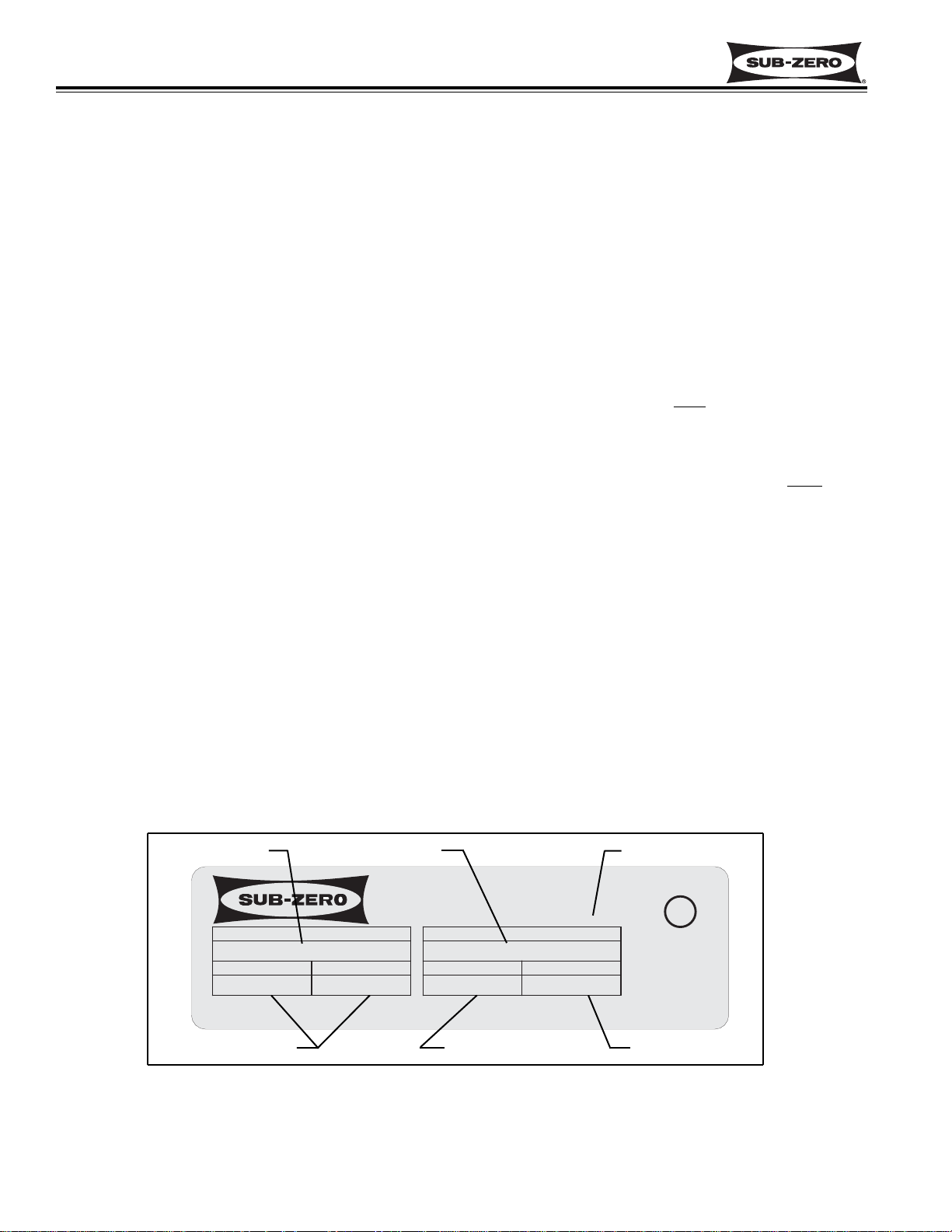
• The serial number tag is located on the left side wall of
the upper drawer compartment. (See Figures 1-1, for
serial tag layout)
700TCI 2 0000000
7.0
9.0 8.1 R134a
Figure 1-1. Serial Tag Layout
(The serial number tag is located on the left side wall of the upper drawer compartment.)
Jul 2000
Model Number
Serial Number
Manufacture Date
Refrigerant Charge
Total Amps Refrigerant Type
MODEL
FREEZER CO., INC.
REFRIGERATOR
PRODUCT SERVICE 1-800-222-7820
FREEZER
LISTED HOUSEHOLD
REFRIGERATOR OR FREEZER
MADISON, WI
SERIAL NUMBER
TOTAL AMPS
115Vac, 60Hz, 1 Phase
REFRIGERANT
U
R
O
CUS
LISTED
776N
Date Code
ALSO VERIFIED IN
ACCORDANCE WITH
ENERGY STANDARD
CAN/CSA-C300-91
L
Page 4
General Information
Integrated (
Integrated (
700-
700-
2) Series
2) Series
1-7
#3756780 - Revision D - July, 2005
MODEL DESCRIPTIONS
The following pages briefly describe the models covered in this manual. Though there are models with and without
icemaker, for the purposes of this manual, only the refrigerator models and the models with icemakers we will
addressed in the succeeding sections.
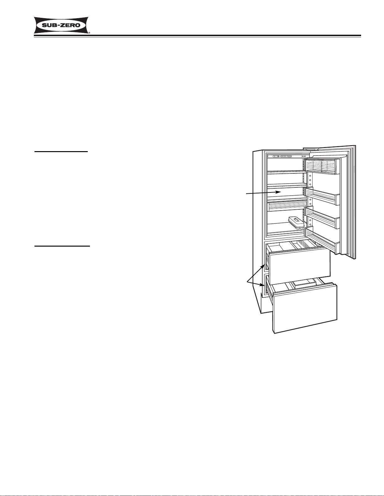
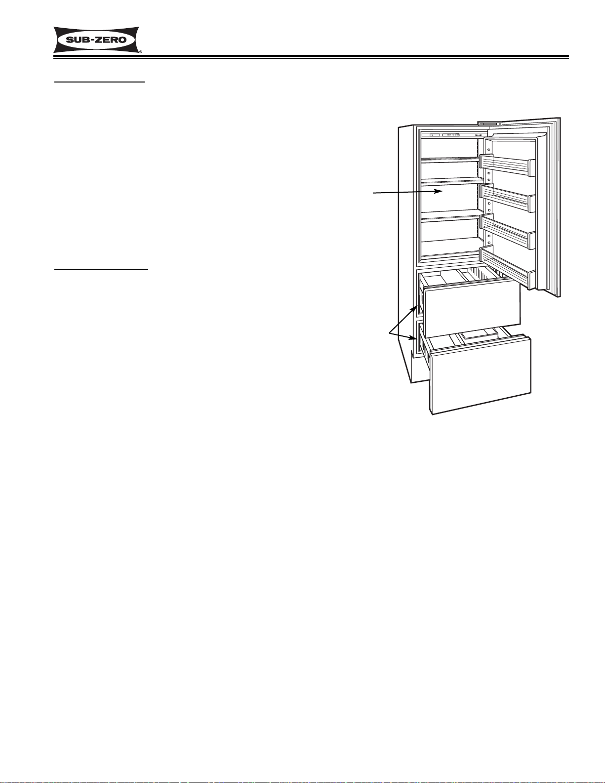
Model 700TC-2 (Figure 1-2)
700 Series
Tall Combo
(Combination Refrigerator / Freezer with Two
Temperature Zones - Upper Refrigerator over
Two Drawer Freezer)
2nd Design Build
(Unit is 80” H x 27” W x 24” D)
Model 700TCI-2 (Figure 1-2)
700 Series
Tall Combo
(Combination Refrigerator / Freezer with Two
Temperature Zones - Upper Refrigerator over
Two Drawer Freezer)
Ice maker Included
2nd Design Build
(Unit is 80” H x 27” W x 24” D)
Figure 1-2. Model 700TC-2 & 700TCI-2
Upper
Refrigerator
Two Drawer
Freezer
Page 5
General Information
Integrated (
Integrated (
700-
700-
2) Series
2) Series
1-8
#3756780 - Revision D - July, 2005
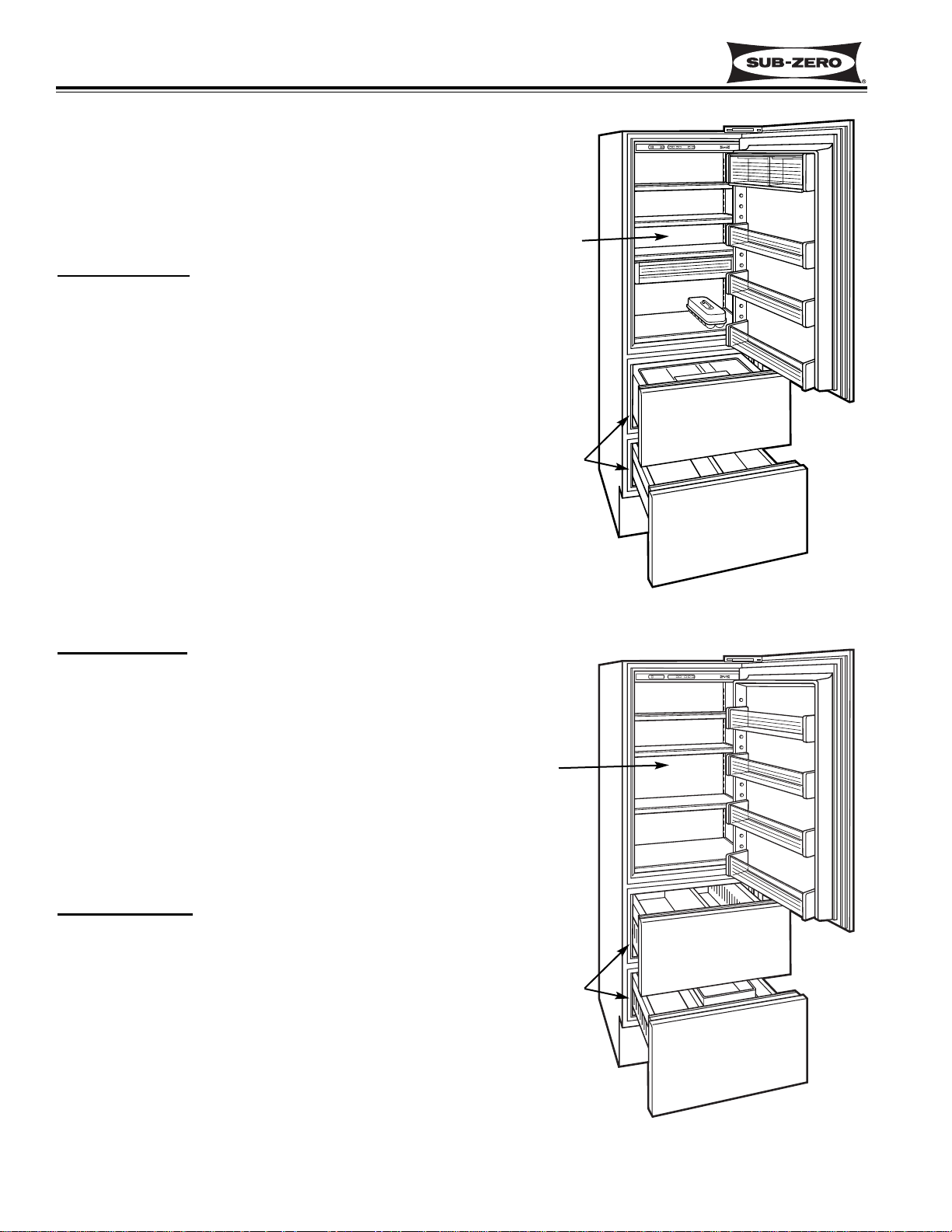
Model 700TR-2 (Figure 1-3)
700 Series
Tall Refrigerator
(All Refrigerator with Two Temperature Zones - Upper
Refrigerator over Two Drawer Refrigerator)
2nd Design Build
(Unit is 80” H x 27” W x 24” D)
Figure 1-3. Model 700TR-2
Upper
Refrigerator
Two Drawer
Refrigerator
Model 700TF-2 (Figure 1-4)
NOTE: This model is replaced by the 700TF-2V as of
serial #1898164 (see following page).
700 Series
Tall Freezer
(All Freezer with One Temperature Zone - Upper
Freezer Section over Two Drawer Freezer Section)
2nd Design Build
(Unit is 80” H x 27” W x 24” D)
Model 700TFI-2 (Figure 1-4)
NOTE: This model is replaced by the 700TFI-2V as of
serial #1898164 (see following page).
700 Series
Tall Freezer
(All Freezer with One Temperature Zone - Upper
Freezer Section over Two Drawer Freezer Section)
Ice maker Included
2nd Design Build
(Unit is 80” H x 27” W x 24” D)
Figure 1-4. Model 700TF-2 & 700TFI-2
Upper
Freezer
Section
Two Drawer
Freezer
Section
Page 6
General Information
Integrated (
Integrated (
700-
700-
2) Series
2) Series
1-9
#3756780 - Revision D - July, 2005
Model 700TF-2V (Figure 1-5)
NOTE: This model replaced the 700TF-2 as of serial
#1898164.
700 Series
Tall Freezer
(All Freezer with One Temperature Zone - Upper
Freezer Section over Two Drawer Freezer Section)
2nd Design Build
Variable Speed Compressor
(Unit is 80” H x 27” W x 24” D)
Model 700TFI-2V (Figure 1-5)
NOTE: This model replaced the 700TFI-2 as of serial
#1898164.
700 Series
Tall Freezer
(All Freezer with One Temperature Zone - Upper
Freezer Section over Two Drawer Freezer Section)
Ice maker Included
2nd Design Build
Variable Speed Compressor
(Unit is 80” H x 27” W x 24” D)
Figure 1-5. Model 700TF-2V & 700TFI-2V
Upper
Freezer
Section
Two Drawer
Freezer
Section
Page 7
General Information
Integrated (
Integrated (
700-
700-
2) Series
2) Series
1-10
#3756780 - Revision D - July, 2005
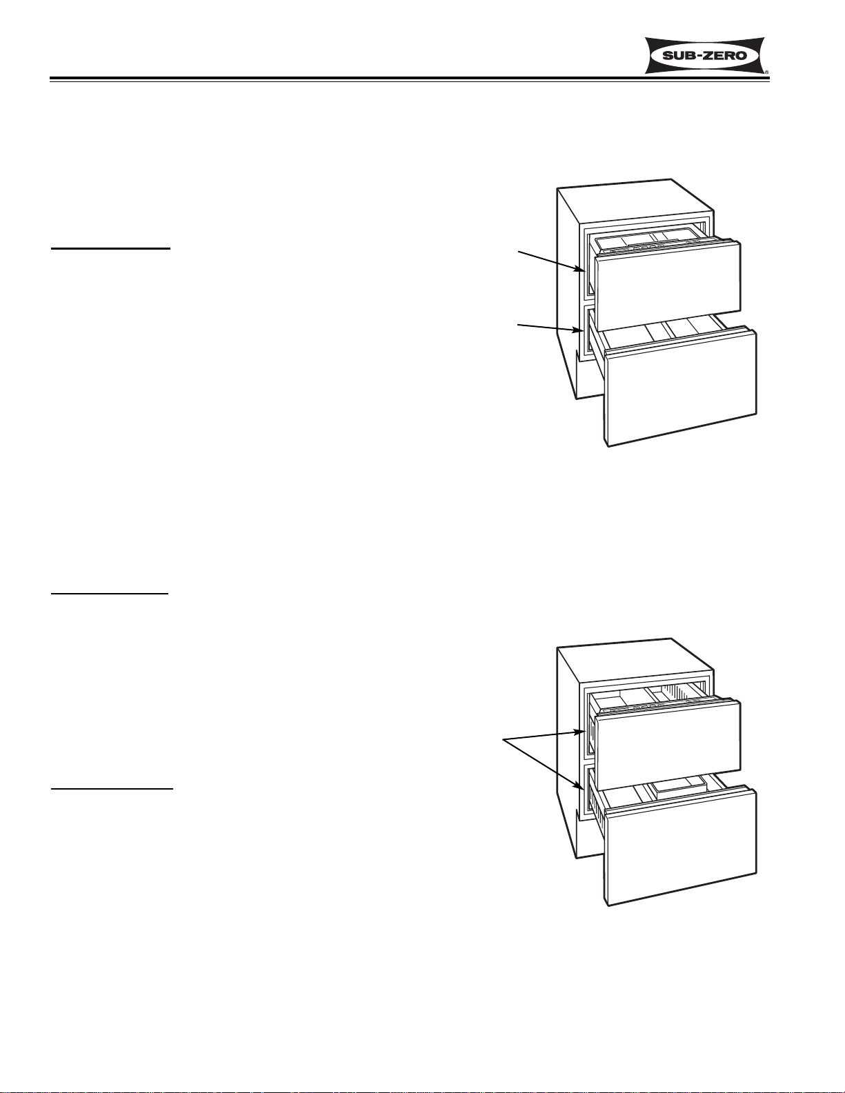
Model 700BR-2 (Figure 1-6)
700 Series
Base Refrigerator
(All Refrigerator with Two Temperature Zones - Upper
Drawer and Lower Drawer)
2nd Design Build
(Unit is 80” H x 27” W x 24” D)
Figure 1-6. Model 700BR-2
Upper
Refrigerator
Zone
Model 700BF-2 (Figure 1-7)
700 Series
Base Freezer
(All Freezer with One Temperature Zone for Both
Drawers)
2nd Build Design
(Unit is 34” H x 27” W x 24” D)
Model 700BFI-2 (Figure 1-7)
700 Series
Base Freezer
(All Freezer with One Temperature Zone for Both
Drawers)
Ice maker Included
2nd Build Design
(Unit is 34” H x 27” W x 24” D)
Lower
Refrigerator
Zone
Freezer
Drawers
Figure 1-7. Model 700BF-2 & 700BFI-2
Page 8
Installation Information
Integrated (
Integrated (
700-
700-
2) Series
2) Series
2-2
#3756780 - Revision D - July, 2005
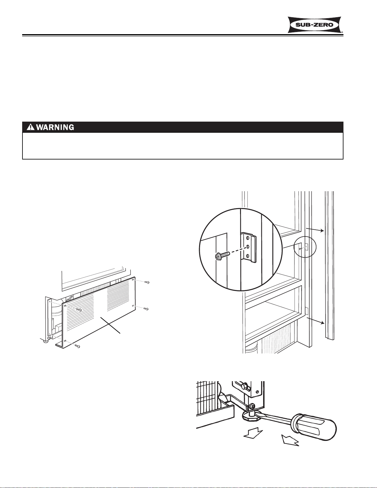
UNIT COULD TIP FORWARD UNDER CERTAIN LOAD CONDITIONS. FAILURE TO INSTALL ANTI-TIP COMPONENTS AND EXTEND LEVELERS TO THE FLOOR ACCORDING TO INSTALLATION MANUAL COULD
RESULT IN SERIOUS PERSONAL INJURY OR DEATH.
INSTALLATION CONSIDERATIONS
This section covers some of the more common installation issues seen by a service technician. An improper installation, though not a valid service issue, has the potential to lead to a customer placing a call for service. Installation
related customer complaints could include, but are not limited to: Unit leveling, unit movement, door misalignment,
doors and drawers not sealing, internal frost or condensation, warm compartment temperatures, exterior condensation, etc.. .
NOTE: If additional installation information is needed, refer to the complete Installation Manual and/or installation
video, or contact the Sub-Zero Technical Assistance Department.
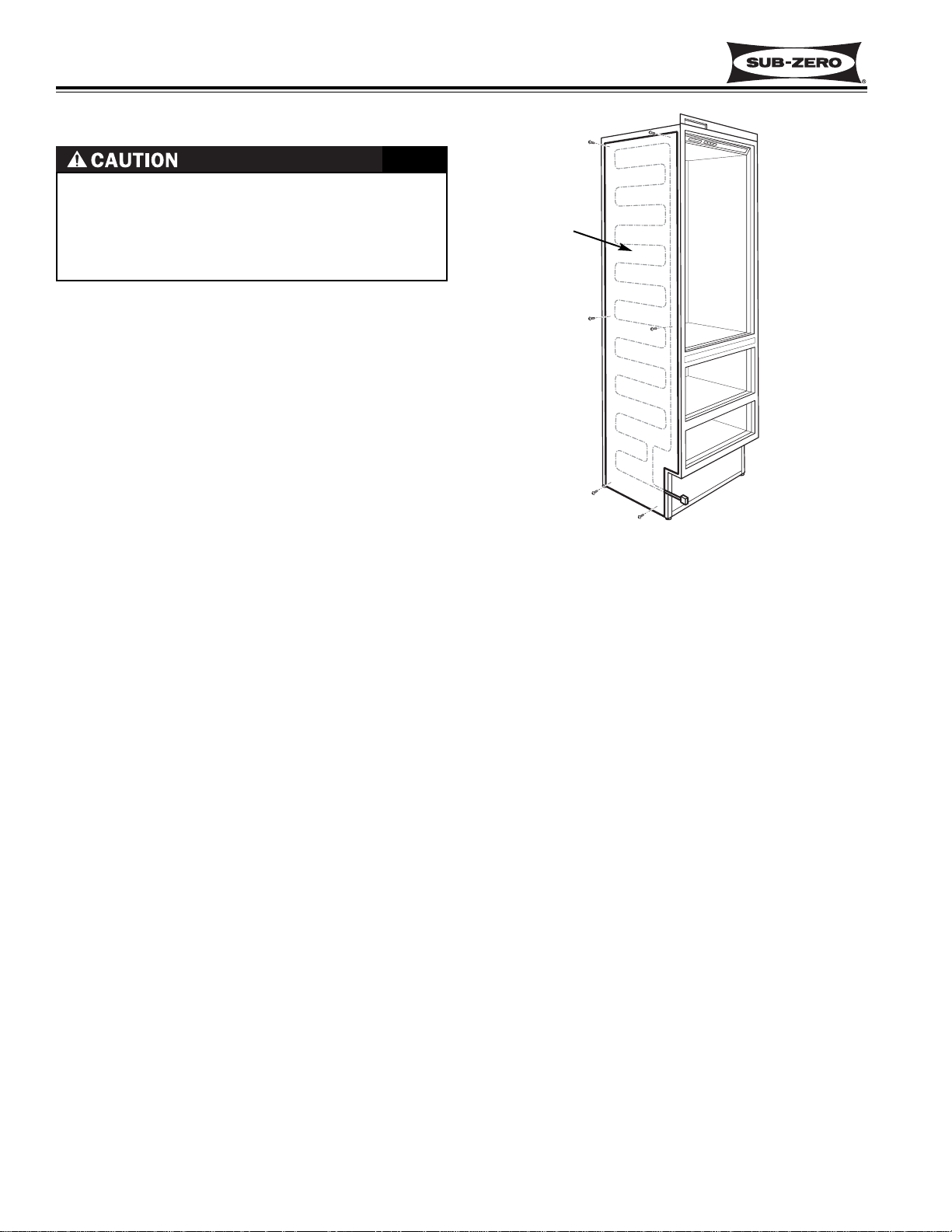
Unit Leveling
NOTE: The kickplate/grille must be removed before
leveling (See Figure 2-1). If the unit has already been
anchored to the cabinets, the side molding strips must
be removed and the anchor screws must be extracted
from the unit to cabinet brackets before leveling (See
Figure 2-2). These components must be reinstalled
after leveling.
Figure 2-2. Side Molding & Bracket
Figure 2-1. Kickplate/Grille Removal
Figure 2-3. Adjusting Front Levelers
To level the unit, turn the front leveling legs counterclockwise to raise the front or clockwise to lower it. To
assist in turning the front leveling legs up or down, use
a standard straight-blade screwdriver and place it in the
foot of the front leg, then rotate the leveler foot in the
desired direction (See Figure 2-3).
Kickplate / Grille
Page 9
Installation Information
Integrated (
Integrated (
700-
700-
2) Series
2) Series
2-3
#3756780 - Revision D - July, 2005
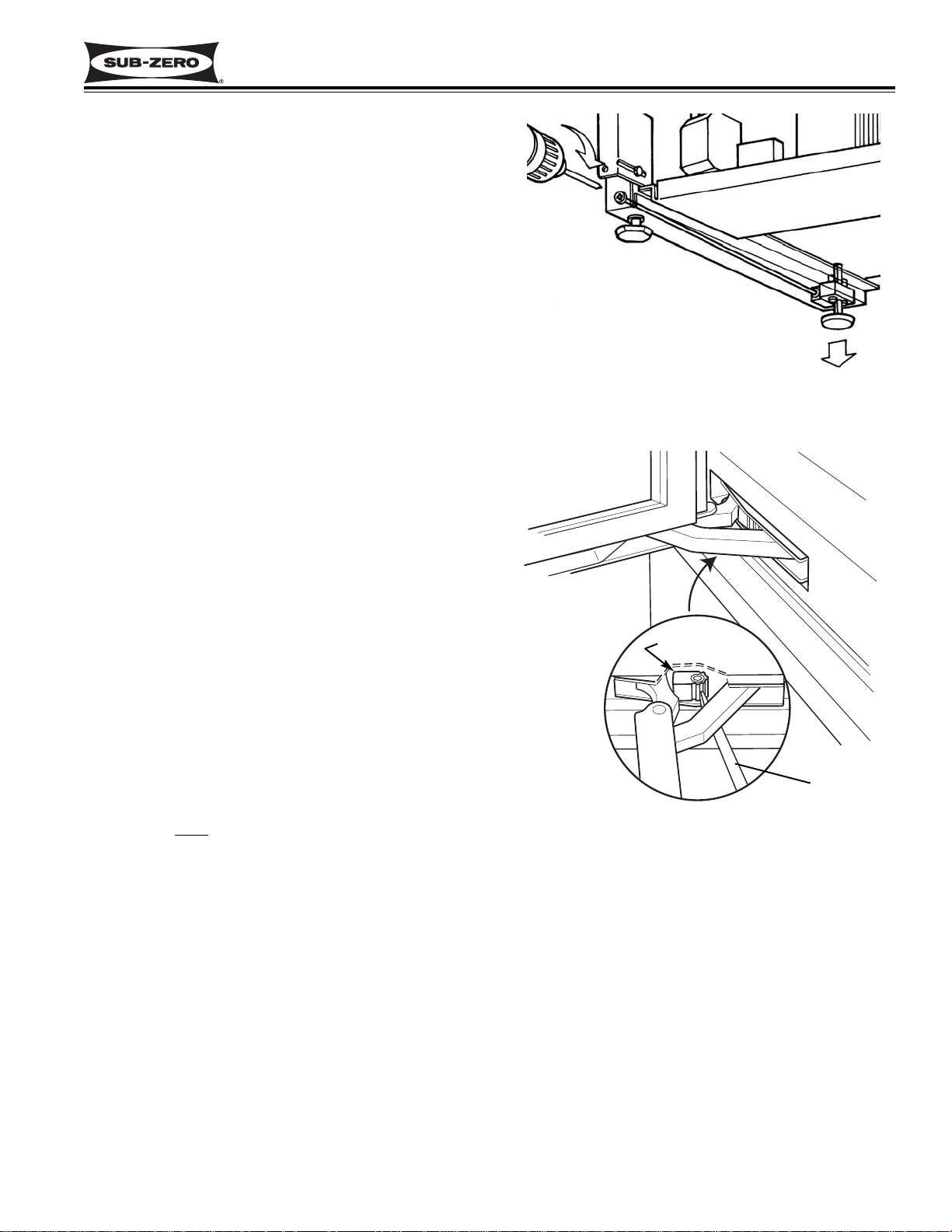
Figure 2-4. Adjusting Rear Levelers
Figure 2-5. 90° Door Stop Cam
Screwdriver
90° Stop Cam
The rear levelers are adjusted from the front of the
base by turning the Phillips head adjusting screw. The
long adjusting screw reaches all the way to the rear leveler assembly. Turn the screw clockwise to raise the
rear or counterclockwise to lower it (See Figure 2-4).
NOTE: The rear leveling legs will only move 1/16” for
every 18 revolutions of the Phillips head screw. Do not
over torque. Use the lowest torque setting on any
power screwdriver. Do not turn rear leveling legs by
hand, doing so will damage the assembly.
Door and Drawer Adjustment
The doors and drawers on 700-2 Series units are nonadjustable. Instead, the door and/or drawer panels
must be adjusted if there is an alignment problem.
Refer to the Installation Manual and/or installation video
for panel installation and adjustment.
NOTE: The unit must be level before attempting to
adjust the door and drawer panels.
NOTE: If the door has problems closing, see Tall Unit
Door Hinge Operation Test Procedures and Corrections
at the end of the Troubleshooting Guide.
Door Stop Adjustment
700-2 Series tall units have a 90° door stop cam built
into the hinge system. The 90° door stop cam is located in the center portion of each hinge. To adjust it, use
a standard straight-blade screwdriver to rotate the cam
until it reaches the stop point (See Figure 2-5).
NOTE: You must
make this adjustment at both bottom
and top hinge.
Page 10
Installation Information
Integrated (
Integrated (
700-
700-
2) Series
2) Series
2-4
#3756780 - Revision D - July, 2005
Dual Unit Installations
• If two Tall units are installed side by side and are 2”
or less apart, part #TTDUAL should be utilized.
(See Figure 2-6)
• If two Base units are installed side by side and are
2” or less apart, part #BBDUAL should be utilized
• If a Tall unit is installed next to a Base unit and they
are 2” or less apart, part #BBDUAL should be utilized.
Complete installation instructions are supplied with the
#BBDUAL and #TTDUAL packages.
If two or more units are placed side by side and are
2” or less apart, a dual unit heater package must be
applied to the left side of the right hand unit.
Failure to install the dual unit heater package could
result in exterior condensation between the units.
Figure 2-6. Dual Unit Heater (#TTDUAL Shown)
Apply heater
to left side of
right hand
unit
Page 11

Electronic Control
Integrated (
Integrated (
700-
700-
2) Series
2) Series
3-1
#3756780 - Revision D - July, 2005
SECTION 3
ELECTRONIC CONTROL
SYSTEM INFORMATION
NOTE: The Electronic Control System used in an
Integrated (700-2) Tall Unit differs from the Electronic
Control System used in a Integrated (700-2) Base
Unit. For
this reason, Section 3 is divided into two parts. The first
part pertains to the Control System in T
all Units. The sec-
ond part pertains to the Control System in Base Units.
Page 12
Electronic Control
Integrated (
Integrated (
700-
700-
2) Series
2) Series
3-2
#3756780 - Revision D - July, 2005
T
erm/Component Definition / Description
Control Board …………………………..The printed-circuit board (PC Board) contains the microprocessor, relays and
electrical connections which control and monitor all functions and operations
of the unit.
Microprocessor ………………………... An electrical component on the control board which receives electrical signals
from other components, processes that information, then sends an electrical
signal to the relays on the board to open or close, and other electronic components in the unit to switch on or off.
Relay …………………………………… The electrical components on the control board which switch other compo-
nents in the unit ON and OFF when instructed to do so by the microprocessor.
LCD (Liquid Crystal Display) ……...... That part of the control board seen at the control panel which displays com-
partment temperatures, service annunciators, etc. . .
Control Panel Assembly ………………The information input and read-out area of the electronic control system,
located at the top of the upper Compartment.
Membrane Switch …………………….. An integral part of the control panel assembly, which consists of the function
keys used for all input operations to the electronic control system.
Keys (Function Keys) ………………… The buttons on the Membrane switch used for input operations. (The keys
are: UNIT ON/OFF, ALARM ON/OFF, ICE ON/OFF, WARMER, COLDER)
Annunciators …………………………... The words and numbers that are displayed at the control panel assembly.
(Example: Temperature displays, alarm bell indicator, SERVICE indicator, and
ICE system indicator)
Display Units…………………………... The temperatures displayed may be in fahrenheit units of measure (°F) or in
celsius units of measure (°C). A series of key strokes allows this to be
changed back and forth.
Set-Point ……………………………….. The desired compartment temperature, established by pressing the COLDER
or WARMER keys.
High Offset (Cut-in)………………….....As the compartment air temperature cycles up and down, this is the maxi-
mum compartment temperature that the electronic control system will allow
before calling for cooling.
Low Offset (Cut-out)…………………... As the compartment air temperature cycles up and down, this is the minimum
compartment air temperature that the electronic control system will allow
before interrupting cooling.
Thermistor (Temperature Sensor) ….. A resistor with which resistance changes as the temperature around it
changes. For electronic control system purposes, the microprocessor measures this resistance and displays it as a temperature reading at the LCD.
ELECTRONIC CONTROL TERMINOLOGY & COMPONENT DESCRIPTIONS
All Integrated 700-2 Series units utilize an electronic control system. The electronic control system monitors, regulates and controls a variety of functions. The electronic control system also displays temperature readings, ice
maker system operation, possible problems with the unit and door ajar alarm status. The table below defines some
basic electronic control system terminology and describes some of the electronic control system components. An
understanding of the following information is needed in order to comprehend the input operations and functions of
the electronic control system.
Page 13
Electronic Control
Integrated (
Integrated (
700-
700-
2) Series
2) Series
3-3
#3756780 - Revision D - July, 2005
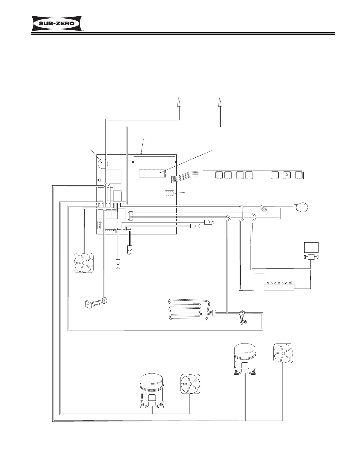
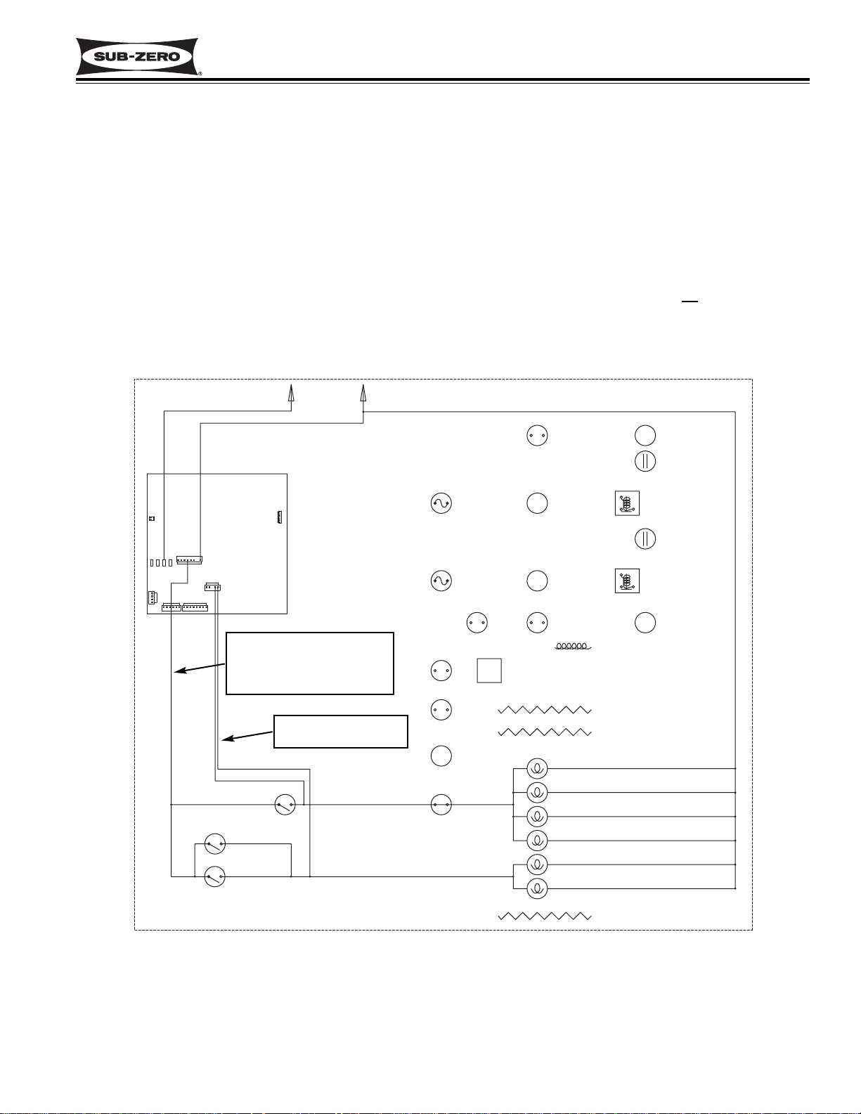
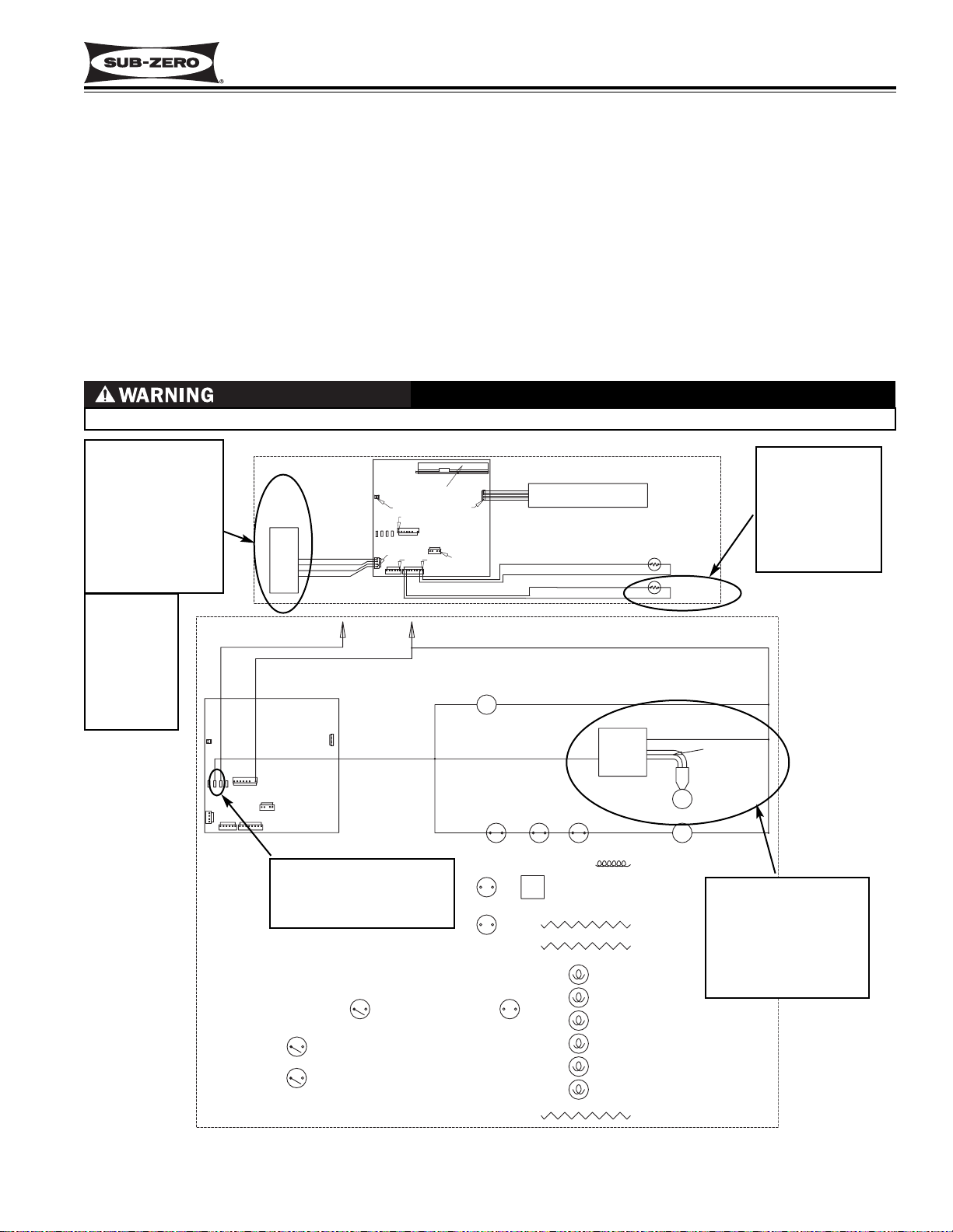
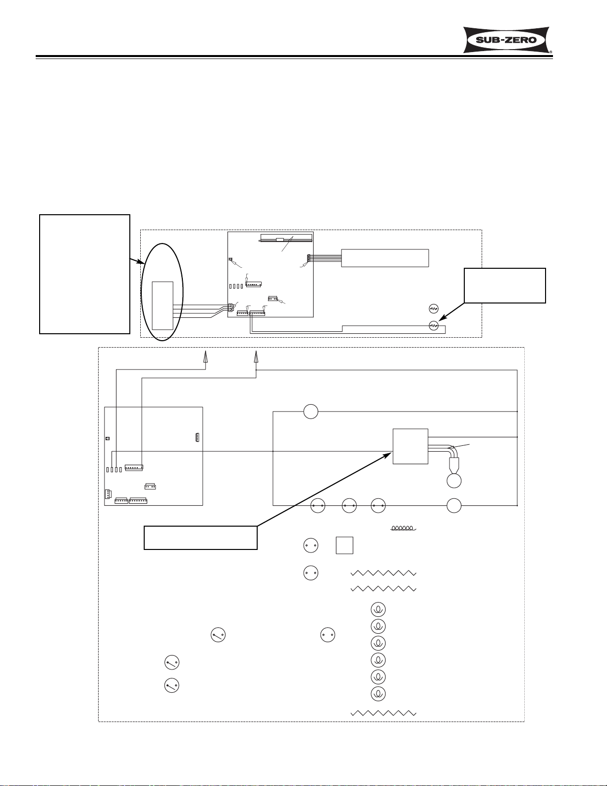
BASIC 700- 2 TALL UNIT ELECTRONIC CONTROL SYSTEM
Input operations for the electronic control system are performed at the control panel (located at the top of the upper
compartment), with monitoring, regulating and controlling functions taking place at the control board (located directly
behind the control panel). Temperatures and possible problems with the unit are illuminated in the control panel at
the LCD. This page illustrates a basic 700 Series electronic control system (Model 700TCI-2 used, See Figure 3-1).
The entire electronic control system is described in greater detail on the following pages.
Figure 3-1. Basic 700TCI-2 Electronic Control System Diagram
ALARM BELL
COND
FAN
R
FILL TUBE
HEATER
RRRR
RR R
FRE CMPRTMNT
THERMISTOR
CONTROL BOARD
LCD
FRE EVAP
THERMISTOR
DEFROST
HEATER
L1
115 VOLTS
60 CYCLES
MICROPROCESSOR
CONTROL PANEL / MEMBRANE SWITCH
FREEZER
BOARD CONFIGURING
RESISTORS
REF EVAP
THERMISTOR
REF CMPRTMNT
THERMISTOR
NEUT
WARMERCOLDER
DEFROST MONITOR LINE
WARMERCOLDER
REFRIGERATOR
LIGHT
SWITCH
SOL. MONITOR LINE
DEFROST TERMINA T OR
ICE
ON/OFF
ON/OFF
DOOR AJAR
MONITOR LINE
WATER
SOLENOID
ICEMAKER
LIGHTS
ON/OFF
UNIT
REFRIG
COMP
FREEZER
FREEZER
COMP
EVAP FAN
REFRIG
EVAP FAN
Page 14
Electronic Control
Integrated (
Integrated (
700-
700-
2) Series
2) Series
3-4
#3756780 - Revision D - July, 2005
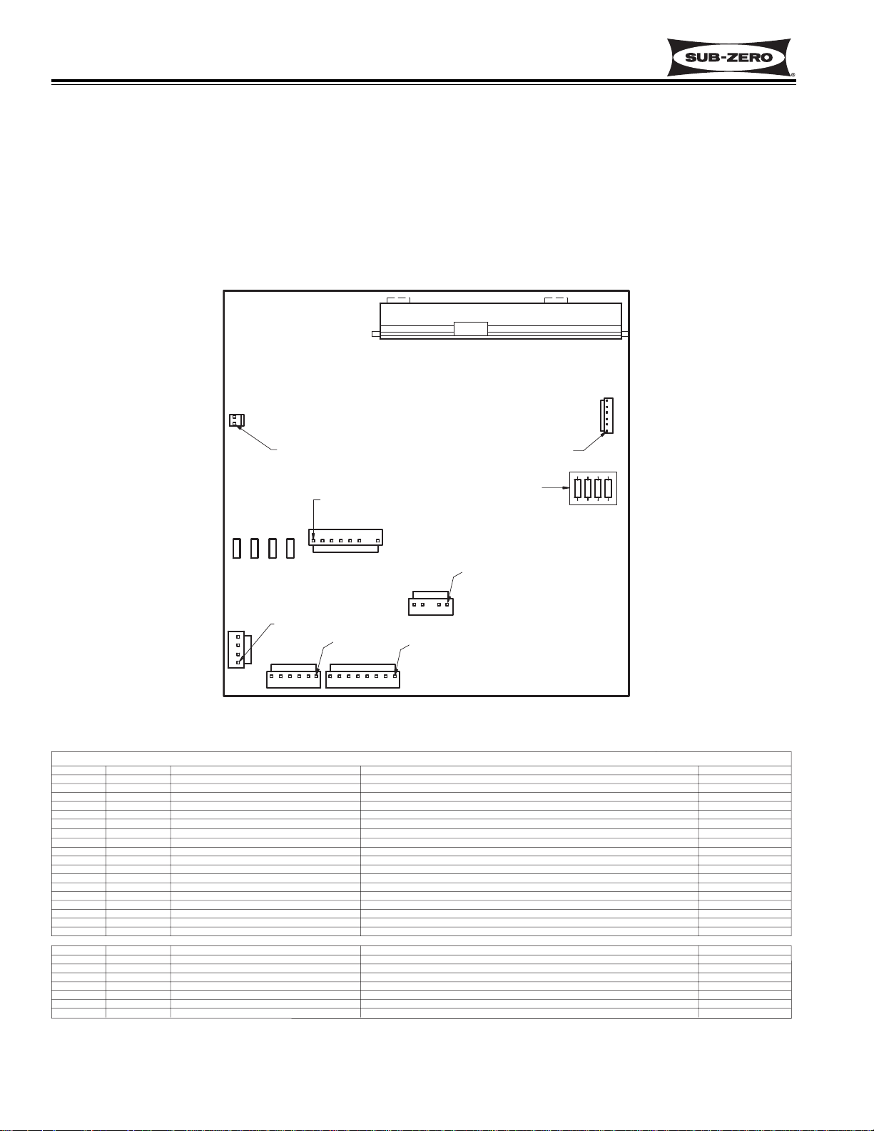
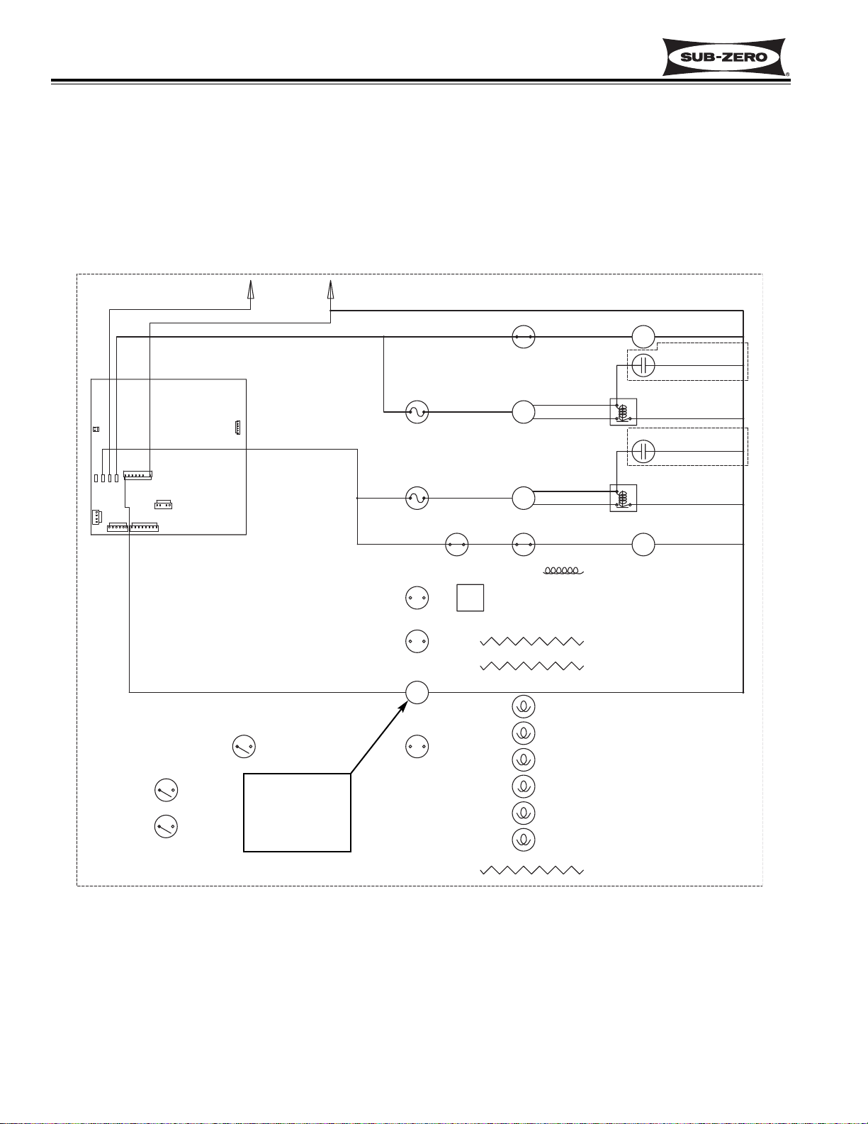
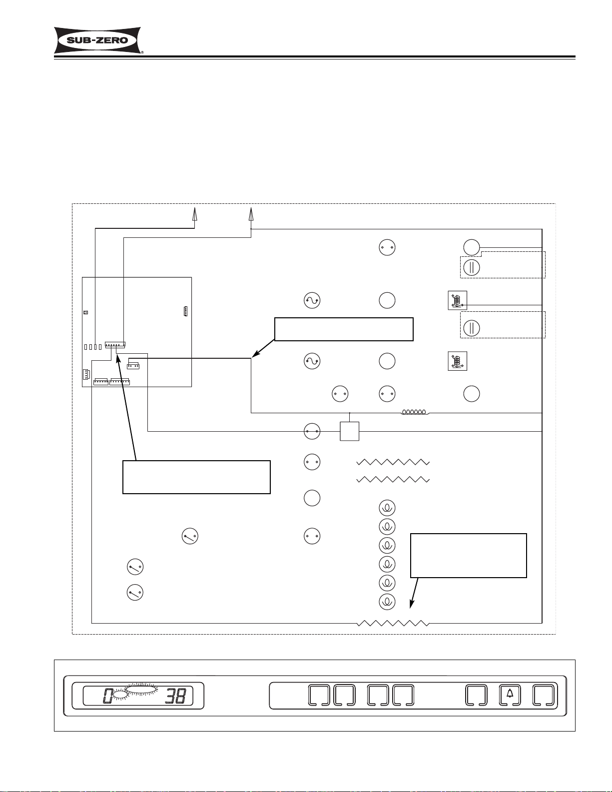
Figure 3-2. 700-2 Tall Unit Control Board Layout
Figure 3-3. 700-2 Tall Unit Control Board Summary Table (700TC/I-2 Summary Table Shown)
700-2 TALL UNIT CONTROL BOARD LAYOUT AND SUMMARY TABLE
The electrical connection points on the 700-2 tall unit control board are labeled alphanumerically. These labels correspond with the alphanumeric control board summary table, located on all 700 Series wiring diagrams. By referencing the summary table, it is possible to identify which components are connected at which connection points on
the control board. Below is a layout diagram of the control board, and a copy of a summary table. (See Figures 3-2
and 3-3)
NOTE: All components on the control board are non-replaceable. If a problem with the control board is identified,
the complete control board must be replaced.
LCD (DISPLAY)
CIRCUIT
E2
DEF HTR
E7
E10
E6
J7-1 C FAN
J7-2
J7-3
J7-4
J7-5
J7-6
J7-7
J7-8
J4-1
J4-2
J4-3
J4-4
J4-5
LOW VOLTAGE THERMISTOR CIRCUITS
J1-1
J1-2
J1-3
J1-4
J1-5
J1-6
J1-7
J1-8
FCOMP
L1
RCOMP
E FAN
IACC
LITES
ICE
NEU
F DR
R DR
EVAP FRZ
EVAP FRZ
EVAP REF
EVAP REF
REF
REF
FRZ
FRZ
DESCRIPTION
120 VOLT CIRCUITS
DEFROST HEATER
FRZ COMPRESSOR
POWER IN
REF COMPRESSOR
CONDENSER FAN
NOT USED
ICE MAKER ACC (FILL TUBE)
LIGHTS
ICE MAKER POWERS ICE MAKER
NOT USED
NOT USED(NO PIN)
NEUTRAL
DRAWER LIGHTS SENSE
DOOR LIGHTS SENSE
NOT USED(NO PIN)
DEF SENSOR
ICE MAKER VALVE SENSOR
FRZ EVAP
FRZ EVAP
REF EVAP
REF EVAP
REF COMPARTMENT
REF COMPARTMENT
FRZ COMPARTMENT
FRZ COMPARTMENT
J5
PIN 1
PIN 1
BOARD CONFIGURING
RESISTORS
J7
E7 E10 E6E2
PIN 1
J4
J3
PIN 1
J2
PIN 1
J1
PIN 1
CONTROL BOARD SUMMARY
FUNCTION COLOR
POWERS DEFROST CIRCUIT
POWERS FRZ COMPRESSOR (DRAWERS)
POWER INTO BOARD
POWERS REF COMPRESSOR (DOOR)
POWERS CONDENSER FAN
POWERS FILL TUBE HEATER AND ACCESSORIES
POWERS LIGHTS
NEUTRAL INTO BOARD
SENSES IF EITHER DRAWER OPEN
SENSES IF DOOR OPEN
SENSES WHEN DEF HEATER SHUTS OFF
SENSES WATER VALVE ACTIVATION
SENSES FRZ EVAP TEMP (DRAWERS)
SENSES FRZ EVAP TEMP (DRAWERS)
SENSES REF EVAP TEMP
SENSES REF EVAP TEMP
SENSES REF CABINET TEMP
SENSES REF CABINET TEMP
SENSES FRZ CABINET TEMP (DRAWERS)
SENSES FRZ CABINET TEMP (DRAWERS)
PIN 1
J6
BLUE
PURPLE
BLACK
GRAY
WHITE/RED
WHITE/BLUE
YELLOW
PINK
WHITE
ORANGE
ORANGE
GRAY/WHITE
TAN
ORANGE/RED
BLUE/RED
ORANGE/YEL
BLUE/YELLOW
BLUE/WHITE
BLUE/WHITE
BLUE/BLACK
BLUE/BLACK
Page 15
Electronic Control
Integrated (
Integrated (
700-
700-
2) Series
2) Series
3-5
#3756780 - Revision D - July, 2005
UNIT
ICE
WARMER
COLDER
REFRIGERATOR
ON/OFF
ON/OFF
ON/OFF
WARMER
COLDER
FREEZER
ICE
SERVICE
OFF
700-2 TALL UNIT CONTROL PANEL LAYOUT
Please note that in the first part of this section, an illustration of the 700TC/I-2 control panel is used most often.
(See Figure 3-4)
Figure 3-4. 700-2 Tall Unit Control Panel Layout (700TC/I-2 Control Panel Shown)
WHEN IN OFF MODE, 115 VOLTS AC IS STILL PRESENT AT CONTROL BOARD!
UNIT
ICE
WARMER
COLDER
REFRIGERATOR
ON/OFF
ON/OFF
ON/OFF
WARMER
COLDER
FREEZER
Figure 3-5. 700-2 Tall Unit ON/OFF, Press UNIT ON/OFF Key
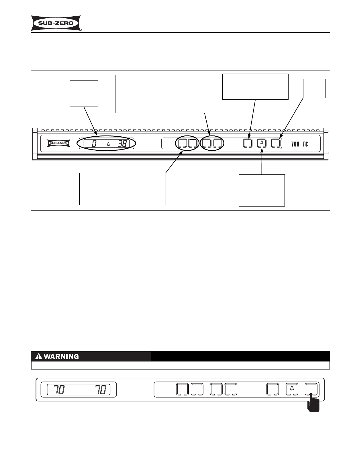
BASIC 700-2 TALL UNIT ELECTRONIC CONTROL INPUT OPERATIONS
Following are illustrations which show the basic input operations performed at the 700-2 tall unit control panel.
Switching the unit ON and OFF, adjusting the set-point (temperature adjustments), switching the ice maker system
ON and OFF, and enabling and disabling the door ajar alarm feature will be explained. Please note that the 700TC/I-
2 control panel is used for most illustrations of the control panel, and in most cases Fahrenheit readings are shown.
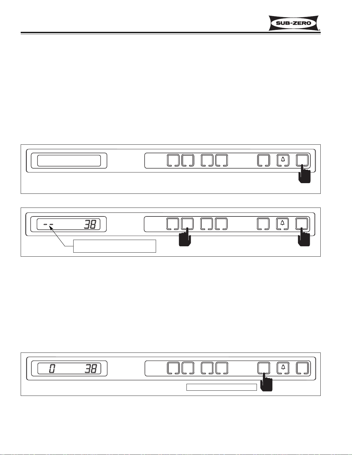
Unit ON/OFF
All Integrated 700-2 Series units are shipped in the OFF Mode and when power is supplied to the unit, a trace of the
word “OFF” is visible on the LCD. By pressing and releasing the UNIT ON/OFF key, (See Figure 3-5.) power is
allowed past the control board to the rest of the unit. This will be indicated by the unit lights and LCD at the control
panel illuminating.
NOTE: Whenever the unit is switched off using the the UNIT ON/OFF key, a trace of the word “OFF” will be visible
on the LCD as long as there is power to the unit.
UNIT
ON/OFF
KEY
DOOR / DRAWER
AJAR
ALARM
ON/OFF
KEY
ICEMAKER SYSTEM
ON/OFF
KEY
(Not present on 700TR-2)
REFRIGERATOR
SET-POINT
ADJUSTMENT
KEYS
(Upper door section on 700 TR-2)
(Not present on 700TF/I-2 or 700TF/I-2V)
FREEZER
SET-POINT
ADJUSTMENT
KEYS
(Lower Drawer section on 700TR-2)
LCD
Liquid
Crystal
Display
SERVICE
ICE
Jake Dog was here
OFF
FREEZER
COLDER
WARMER
COLDER
WARMER
REFRIGERATOR
ICE
ON/OFF
ON/OFF
ON/OFF
UNIT
FREEZER
COLDER
WARMER
COLDER
WARMER
REFRIGERATOR
ICE
ON/OFF
ON/OFF
UNIT
ON/OFF
Page 16
Electronic Control
Integrated (
Integrated (
700-
700-
2) Series
2) Series
3-6
#3756780 - Revision D - July, 2005
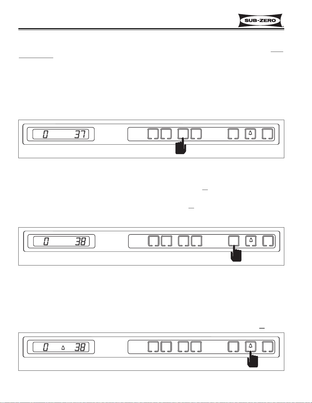
Adjusting Set-Point (Temperature Adjustment)
To adjust the set-points, press the appropriate compartment WARMER or COLDER key on the control panel in multi
-
ple key strokes
until the desired set-point is achieved. One key stroke equals a one degree (Fahrenheit or Celsius)
change. (See Figure 3-6)
NOTE: Temperature ranges are -5°F (-21°C) to +5°F (-15°C) in freezer compartment, with an initial set-point of
0°F (-18°C), and +34°F (+1°C) to +45°F (+7°C) in refrigerator compartment, with an initial set-point of +38°F (+3°C).
NOTE: When checking set-points, remember that the initial key stroke of the WARMER or COLDER key will change
the previous set-point by one degree (Fahrenheit or Celsius).
NOTE: The set-point will be displayed on the LCD for 10 seconds after the last WARMER or COLDER key stroke.
After the 10 second delay, the compartment temperature will be displayed. As the compartment temperature
changes, the temperature displayed on the LCD will change, by no more than one degree per minute.
UNIT
ICE
WARMER
COLDER
REFRIGERATOR
ON/OFF
ON/OFF
ON/OFF
WARMER
COLDER
FREEZER
Figure 3-6. Adjusting the Set-Point - Press WARMER or COLDER Key In Multiple Key Strokes
Icemaker System ON/OFF
All Integrated 700-2 Series units are shipped with the icemaker system switched of
f. By pressing and releasing the
ICE ON/OFF key on the control panel, power is allowed to the icemaker system, and “ICE” is displayed on the LCD.
(See Figure 3-7) To deactivate the icemaker system, press and release the ICE ON/OFF key again and the “ICE”
annunciator will disappear from the LCD indicating the icemaker system is of
f.
NOTE: When the unit is in “Sabbath Mode,” the icemaker system is de-energized. Sabbath Mode will be explained
in UNIQUE ELECTRONIC CONTROL SYSTEM INPUT OPERATIONS.
Figure 3-7. Icemaker System ON/OFF - Press ICE ON/OFF Key
ICE
UNIT
ICE
WARMER
COLDER
REFRIGERATOR
ON/OFF
ON/OFF
ON/OFF
WARMER
COLDER
FREEZER
Door Ajar Alarm Bell ON/OFF
All Integrated 700-2 Series units are equipped with a door ajar alarm feature. When activated the alarm will alert a
customer if a door or drawer is left or stuck open. To enable the door ajar alarm feature, press and release the door
ajar alarm bell ON/OFF key on the control panel. A bell annunciator will illuminate on the LCD indicating the alarm
feature is active (See Figure 3-8). Now, if a door or drawer is open for 30 seconds (See “NOTE” in Figure 3-8), the
bell annunciator will flash and the audible alarm will beep. To disable the door ajar alarm, simply press the door ajar
alarm bell ON/OFF key and the bell annunciator on the LCD will disappear, indicating the alarm feature is of
f.
Figure 3-8. Door Ajar Alarm ON/OFF, Press Alarm Bell ON/OFF Key
UNIT
ICE
WARMER
COLDER
REFRIGERATOR
ON/OFF
ON/OFF
ON/OFF
WARMER
COLDER
FREEZER
FREEZER
COLDER
WARMER
COLDER
WARMER
REFRIGERATOR
ICE
ON/OFF
ON/OFF
UNIT
ON/OFF
ICE
FREEZER
COLDER
WARMER
COLDER
WARMER
REFRIGERATOR
ICE
ON/OFF
ON/OFF
UNIT
ON/OFF
FREEZER
COLDER
WARMER
COLDER
WARMER
REFRIGERATOR
ICE
ON/OFF
ON/OFF
UNIT
ON/OFF
Page 17
Electronic Control
Integrated (
Integrated (
700-
700-
2) Series
2) Series
3-7
#3756780 - Revision D - July, 2005
FUNCTIONS OF 700 TALL UNIT ELECTRONIC CONTROL SYSTEM
The following few pages explain the monitoring, regulating and controlling functions of the electronic control system.
Signal trace schematic illustrations for the model 700TC/I-2 are used to demonstrate current flow for the function
being explained.
NOTE: Only normal operating electronic control functions are described along with problems which could cause
error annunciators. All possible malfunctions are addressed in the Troubleshooting Guide.
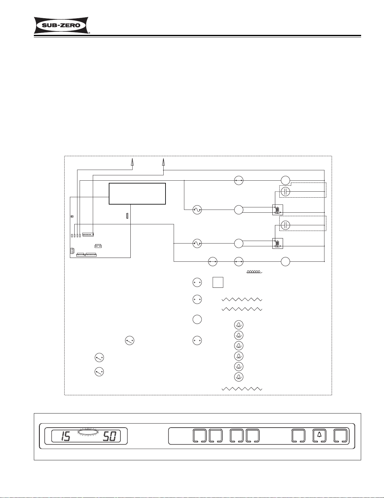
Supply Power to the Lighting System
115 Volts are supplied to the lighting system through the control board when the unit is switched on
by pressing the
UNIT ON/OFF key. (See Figure 3-9.)
NOTE: Disabling the lighting system (Sabbath Mode) is covered in Unique Electronic Control Input Operations.
Figure 3-9. 700TC/I-2 Signal Trace Schematic of Lighting System
115 Volts are supplied
through J7 to lighting system
unless unit is switched OFF
or is in Sabbath Mode
NOTE:
Door Ajar Sense Lines
HIGH VOLTAGE
115 VOLTS
BLACK
WHITE
L1
60 CYCLES
NEUT
WHITE
M
J5
E2 E7 E10 E6
J3
J6
J7
J4
J1
J2
M
M
M
ORANGE
ORANGE
REFRIGERATOR
LIGHT SWITCH
ORANGE
ORANGE
FREEZER
LIGHT
SWITCHES
ORANGE
ORANGE
LIGHT
TERMINATOR
M
REFRIGERATOR
LIGHTS
FREEZER
LIGHTS
Page 18
Electronic Control
Integrated (
Integrated (
700-
700-
2) Series
2) Series
3-8
#3756780 - Revision D - July, 2005
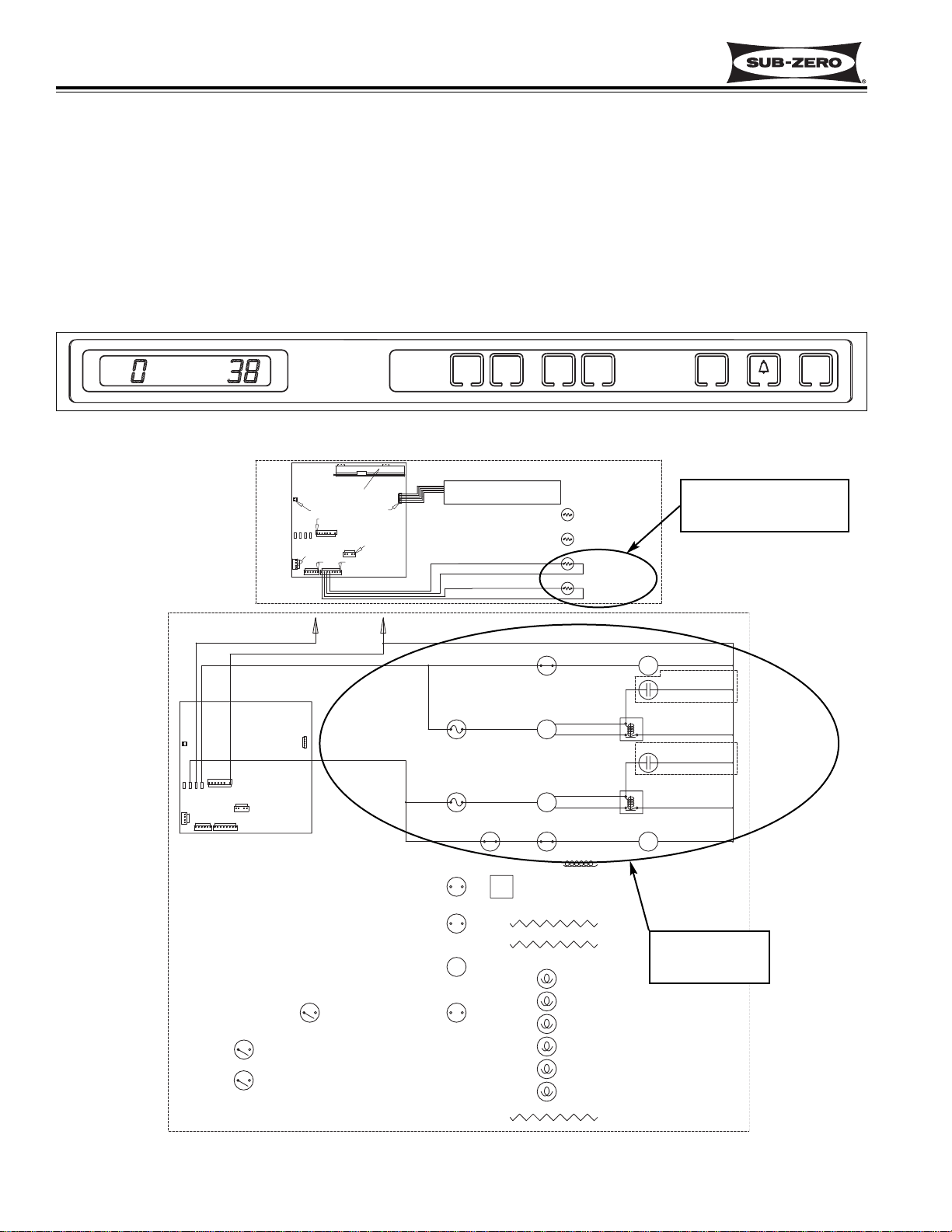
Monitor, Regulate and Display Compartment Temperatures (700TC/I-2, 700TR-2 and 700TF/I-2)
In the models 700TC/I-2, 700TR-2 and 700TF/I-2, the temperature signal from the thermistor in the refrigerator
and/or freezer compartment is monitored by the microprocessor and then displayed on the LCD. Though the compartment air temperature does fluctuate, the LCD displays the average temperature (See Figure 3-10). When the
compartment temperature reaches high offset, the microprocessor supplies power to the compressor and evaporator
fan (See Figure 3-11). As the compressor and evaporator fan run, the compartment temperature drops. When the
compartment temperature reaches low offset, the microprocessor interrupts power to the compressor and evaporator
fan, cycling them off.
NOTE: If the average compartment temperature changes, the temperature displayed on the LCD will change by one
degree per minute.
Figure 3-10. Average Compartment Temperature Displayed
UNIT
ICE
WARMER
COLDER
REFRIGERATOR
ON/OFF
ON/OFF
ON/OFF
WARMER
COLDER
FREEZER
Compartments
calling for cooling
(Temp. above high offset)
Compressors and
evaporator fans
energized
Figure 3-11. 700TC/I-2 Signal Trace Schematic (High & Low Voltage) of Regulating Temperatures
HIGH VOLTAGE
J5
E2 E7 E10 E6
J3
J2
WARMER
FREEZER
COLDER
WARMER
COLDER
LOW VOLTAGE
DISPLAY
J5
0
PIN 1
PIN 1
J7
0
E2 E6E10E7
J3
PIN 1
PIN 1PIN 1
J2
0
L1
BLACK
WHITE
J6
J7
J4
J1
GRAY
0
115 VOLTS
60 CYCLES
PURPLE
J1
0
J6
0
PIN 1
PIN 1
0
J4
NEUT
MEMBRANE SWITCH
BLUE W/WHITE STRIPE
BLUE W/WHITE STRIPE
BLUE W/BLACK STRIPE
BLUE W/BLACK STRIPE
WHITE
REFRIGERATOR
FAN SWITCH
REFRIGERATOR
COMPRESSOR
M
REFRIGERATOR
OVERLOAD
PROTECTOR
FREEZER
OVERLOAD
PROTECTOR
FREEZER
PURPLE RED
SWITCHES
COMPRESSOR
M
FAN
REF CAB
THERMISTOR
FZR CAB
THERMISTOR
RED
FREEZER
REFRIGERATOR
REFRIGERATOR
FAN MOTOR
M
RUNNING
CAPACITOR
(WHEN USED)
STARTING
RELAY
RUNNING
CAPACITOR
(WHEN USED)
STARTING
RELAY
FREEZER
FAN MOTOR
M
ICE
ON/OFF
ON/OFF
UNIT
ON/OFF
M
Page 19
Electronic Control
Integrated (
Integrated (
700-
700-
2) Series
2) Series
3-9
#3756780 - Revision D - July, 2005
Control Variable Speed Compressor (700TF/I-2V)
Like other tall units, the temperature signal from the thermistor in a 700TF/I-2V freezer compartment is monitored by
the microprocessor and then displayed on the LCD, and when cooling is called for, the evaporator fan and condenser fan are energized. But, in a model 700TF/I-2V an additional component, the compressor controller, is used to
control the variable speed compressor. How this works is, the temperature difference between the compartment
thermistor and the set-point is monitored by the microprocessor to determine the appropriate speed signal which is
then sent via a low voltage line to the compressor controller. The compressor controller supplies a 230 volt AC, 3phase, 50 - 150 Hz signal, based on the speed signal from the microprocessor, to the compressor. This signal causes the compressor to run at varying speeds. (See Figure 3-12) Speed commands will vary at 0, 1600, 1700, 1800,
2100, 2200, 2400, 2700, 3600 and 4000 RPM, depending on compartment temperature and set-point.
NOTE: In the model 700TF/I-2V, the compressor, evaporator fan and condenser fan will run a great majority of the
time. This is normal. These components will only cycle off during defrost and may also cycle off for short periods of
time if the ambient temperature is low enough.
Figure 3-12. 700TF/I-2V Signal Trace Schematic of Variable Speed Compressor Operation
VOLTAGE EXCEEDING 200 VOLTS MAY BE PRESENT AT COMPRESSOR & COMPRESSOR CONTROLLER!
1. Compartment
temperature
monitored by
microprocessor
3. Low voltage
speed signal sent
from microprocessor to controller, based on
difference
between compartment temperature
and set-point
4. Controller supplies
230 volt AC, 3-phase,
50 - 150 Hz signal
(based on the speed
signal from microprocessor), to compressor.
2. 115 Volts AC supplied to
controller, evaporator
fan, and condenser fan
when cooling is required.
NOTE: con-
troller also
sends signal
back to microprocessor
indicating
compressor
speed status.
HIGH VOLTAGE
J5
E2 E7 E10 E6
J3
J2
LOW VOLTAGE
V SPEED
CONTROL
BOX
PINK W/BLACK
PINK W/RED
YELLOW W/RED
YELLOW W/BLACK
115 VOLTS
60 CYCLES
L1
BLACK
WHITE
J6
PURPLE
J7
J4
J1
DISPLAY
J5
PIN 1
PIN 1
J7
E2 E6E10E7
J3
PIN 1
J2
PIN 1 PIN 1
J1
J4
NEUT
J6
PIN 1
PIN 1
CONDENSER
FAN MOTOR
WHITE
MEMBRANE SWITCH
ORANGE W/RED STRIPE
BLUE W/RED STRIPE
BLUE W/BLACK STRIPE
BLUE W/BLACK STRIPE
FRZ EVAP
THERMISTOR
FRZ CAB
THERMISTOR
M
VSPEED
CONTROL
FREEZER
FAN
PURPLE RED
SWITCHES
BOX
BROWN
BLACK
COMPRESSOR
M
FAN MOTOR
M
LT. BLUE
FREEZER
FREEZER
Page 20
Electronic Control
Integrated (
Integrated (
700-
700-
2) Series
2) Series
3-10
#3756780 - Revision D - July, 2005
Control Condenser Fan Run
The microprocessor senses the 115 volt output supplied to both compressors. If either compressor is running, a signal is sent to the condenser fan relay on the control board to close, supplying power to the condenser fan. If both
compressors are off, the condenser fan is off. (See Figure 3-13)
NOTE: There is only one compressor on the model 700TF/I-2 and 700TF/I-2V. The condenser fan cycles with this sin-
gle compressor. In the model 700TF/I-2V, the condenser fan along with the compressor and evaporator fan will only
cycle off during defrost and may also cycle off for short periods of time if the ambient temperature is low enough.
Figure 3-13. 700TC/I-2 Signal Trace Schematic (High Voltage) of Condenser Fan Operation
Power supplied to
condenser fan
motor if one or
both compressors
are running
HIGH VOLTAGE
115 VOLTS
J5
E2 E7 E10 E6
J3
60 CYCLES
BLACK
J7
J4
J1
J2
L1
WHITE
GRAY
J6
PURPLE
NEUT
WHITE
REFRIGERATOR
FAN SWITCH
REFRIGERATOR
COMPRESSOR
M
REFRIGERATOR
OVERLOAD
PROTECTOR
FREEZER
OVERLOAD
PROTECTOR
FREEZER
FAN
PURPLE RED
SWITCHES
FREEZER
COMPRESSOR
M
RED
REFRIGERATOR
FAN MOTOR
M
RUNNING
CAPACITOR
(WHEN USED)
STARTING
RELAY
RUNNING
CAPACITOR
(WHEN USED)
STARTING
RELAY
FREEZER
FAN MOTOR
M
WHITE/RED
CONDENSER
FAN MOTOR
M
Page 21
Electronic Control
Integrated (
Integrated (
700-
700-
2) Series
2) Series
3-11
#3756780 - Revision D - July, 2005
Figure 3-15. 700TC/I-2 Signal Trace Schematic (High Voltage) of Compressor Electrical System
Figure 3-16. SERVICE Flashing Possibly Because of Several Excessive Compressor Run Periods Occurring
UNIT
ICE
WARMER
COLDER
REFRIGERATOR
ON/OFF
ON/OFF
ON/OFF
WARMER
COLDER
FREEZER
SERVICE
length of compressor
run time is monitored
by microprocessor.
Monitor Compressor Run Duration, Displays If Service may be Needed (700TC/I-2, 700TR-2 and 700TF/I-2)
The microprocessor in the models 700TC/I-2, 700TR-2 and 700TF/I-2 senses the 115 volt output supplied to the
compressor(s), monitoring the length of compressor run time (See Figure 3-15). If several excessive compressor
run periods occur, a signal is sent to the SERVICE annunciator on the LCD to flash (See Figure 3-16).
NOTE: A flashing SERVICE annunciator can indicate excessive compressor run or a faulty refrigerator evaporator
thermistor. Diagnostic Mode (covered later in this section) should be initiated to narrow the search for possibilities.
This is also covered in the Troubleshooting Guide section of this manual.
NOTE: To clear a flashing SERVICE error annunciator, the problem must be corrected, then the unit must be
switched OFF and back ON.
NOTE: If the unit is ever switched OFF then back ON, the compressors will not energize for at least three minutes.
This three minute minimum OFF time is used to protect the compressor and its electricals.
HIGH VOLTAGE
115 VOLTS
J5
E2 E7 E10 E6
J3
60 CYCLES
L1
BLACK
WHITE
GRAY
J6
PURPLE
J7
J4
J1
J2
NEUT
WHITE
REFRIGERATOR
FAN SWITCH
REFRIGERATOR
COMPRESSOR
M
REFRIGERATOR
OVERLOAD
PROTECTOR
FREEZER
OVERLOAD
PROTECTOR
FREEZER
FAN
PURPLE RED
SWITCHES
FREEZER
COMPRESSOR
M
RED
REFRIGERATOR
FAN MOTOR
M
RUNNING
CAPACITOR
(WHEN USED)
STARTING
RELAY
RUNNING
CAPACITOR
(WHEN USED)
STARTING
RELAY
FREEZER
FAN MOTOR
M
M
SERVICE
FREEZER
COLDER
WARMER
COLDER
WARMER
REFRIGERATOR
ICE
ON/OFF
ON/OFF
UNIT
ON/OFF
Page 22
Electronic Control
Integrated (
Integrated (
700-
700-
2) Series
2) Series
3-12
#3756780 - Revision D - July, 2005
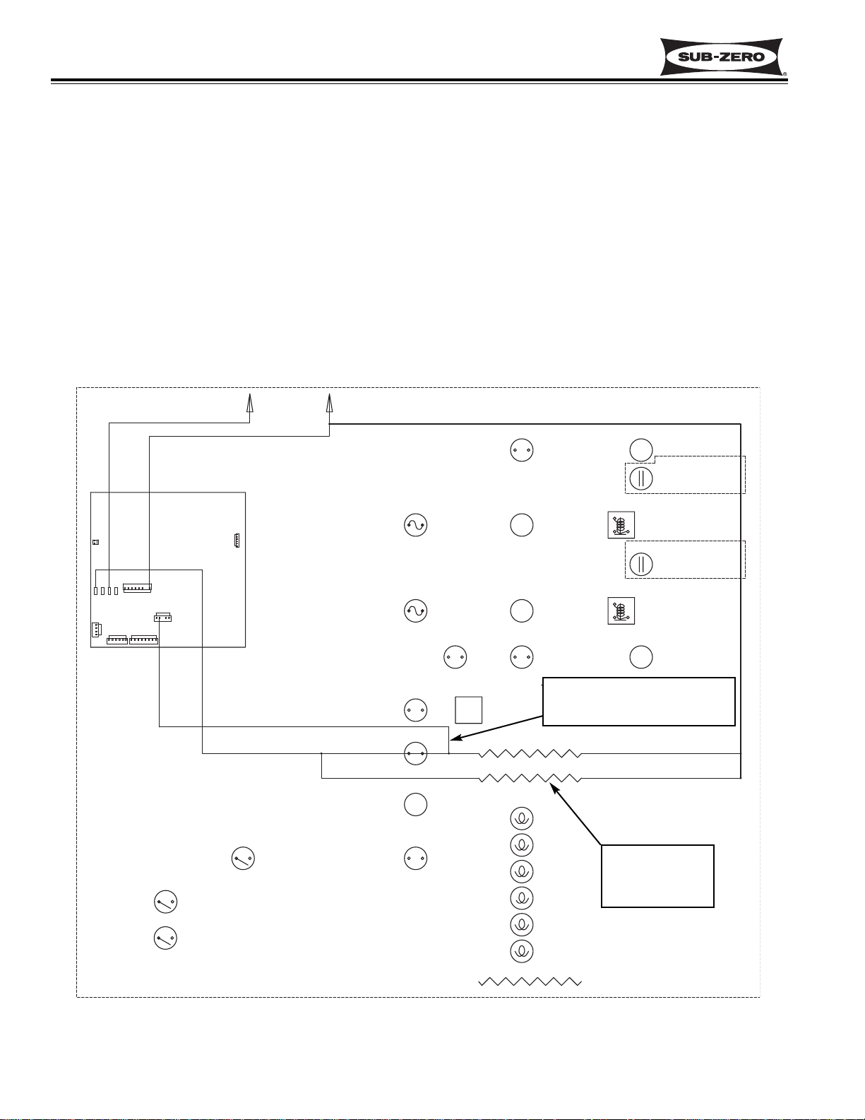
Monitor and Control “Adaptive Defrost” of Freezer Evaporator
Initially the freezer compressor will cycle-run for twelve hours (twenty-four hours in model 700TF/I-2V), after which
the microprocessor sends the signal to the defrost relay on the control board to close. This supplies power to the
defrost heater, and the compressor is switched off (See Figure 3-15). With the “Adaptive Defrost” technique, the
length of time that the heater actually stays on to defrost the evaporator and satisfy the defrost terminator is
observed by the microprocessor. The microprocessor then determines the number of hours before the next defrost.
If the heater stays on for a shorter time than specified, the microprocessor increases the next defrost interval. If the
heater stays on longer than specified, the electronic control decreases the next defrost interval. This is an ongoing
process whereby the defrost time and the defrost interval will vary by unit use.
NOTE: A five minute time delay/dwell follows all defrosts, except in the model 700TF/I-2V where the delay/dwell is
ten minutes. The drain trough heater is energized during defrost and the delay/dwell period.
NOTE: The minimum defrost interval is six hours; The maximum defrost interval is eighty hours; the maximum
defrost duration is twenty-five minutes.
Figure 3-15. 700TC/I-2 Signal Trace Schematic (High Voltage) of Freezer Adaptive Defrost
Length of defrost time monitored
by microprocessor via defrost
sense line
Drain trough
heater energized
during defrost and
delay/dwell period
HIGH VOLTAGE
115 VOLTS
BLACK
L1
WHITE
60 CYCLES
NEUT
WHITE
M
J5
E2 E7 E10 E6
J3
J6
J7
J4
J1
J2
M
M
M
GRAY/WHITE
BLUE
DEFROST
TERMINATOR
30-38 OHMS
155-175 OHMS
M
DEFROST
HEATER
DRAIN TROUGH
HEATER
Page 23

Electronic Control
Integrated (
Integrated (
700-
700-
2) Series
2) Series
3-13
#3756780 - Revision D - July, 2005
Figure 3-15. 700TC/I-2 Signal Trace Schematic (High Voltage) of Compressor Electrical System
Figure 3-16. SERVICE Flashing Possibly Because of Several Excessive Compressor Run Periods Occurring
UNIT
ICE
WARMER
COLDER
REFRIGERATOR
ON/OFF
ON/OFF
ON/OFF
WARMER
COLDER
FREEZER
SERVICE
length of compressor
run time is monitored
by microprocessor.
Monitor Compressor Run Duration, Displays If Service may be Needed (700TC/I-2, 700TR-2 and 700TF/I-2)
The microprocessor in the models 700TC/I-2, 700TR-2 and 700TF/I-2 senses the 115 volt output supplied to the
compressor(s), monitoring the length of compressor run time (See Figure 3-15). If several excessive compressor
run periods occur, a signal is sent to the SERVICE annunciator on the LCD to flash (See Figure 3-16).
NOTE: A flashing SERVICE annunciator can indicate excessive compressor run or a faulty refrigerator evaporator
thermistor. Diagnostic Mode (covered later in this section) should be initiated to narrow the search for possibilities.
This is also covered in the Troubleshooting Guide section of this manual.
NOTE: To clear a flashing SERVICE error annunciator, the problem must be corrected, then the unit must be
switched OFF and back ON.
NOTE: If the unit is ever switched OFF then back ON, the compressors will not energize for at least three minutes.
This three minute minimum OFF time is used to protect the compressor and its electricals.
HIGH VOLTAGE
115 VOLTS
J5
E2 E7 E10 E6
J3
60 CYCLES
L1
BLACK
WHITE
GRAY
J6
PURPLE
J7
J4
J1
J2
NEUT
WHITE
REFRIGERATOR
FAN SWITCH
REFRIGERATOR
COMPRESSOR
M
REFRIGERATOR
OVERLOAD
PROTECTOR
FREEZER
OVERLOAD
PROTECTOR
FREEZER
FAN
PURPLE RED
SWITCHES
FREEZER
COMPRESSOR
M
RED
REFRIGERATOR
FAN MOTOR
M
RUNNING
CAPACITOR
(WHEN USED)
STARTING
RELAY
RUNNING
CAPACITOR
(WHEN USED)
STARTING
RELAY
FREEZER
FAN MOTOR
M
M
SERVICE
FREEZER
COLDER
WARMER
COLDER
WARMER
REFRIGERATOR
ICE
ON/OFF
ON/OFF
UNIT
ON/OFF
Page 24
Electronic Control
Integrated (
Integrated (
700-
700-
2) Series
2) Series
3-14
#3756780 - Revision D - July, 2005
Figure 3-17. 700TF/I-2V Signal Trace Schematic of Compressor Electrical System
3. Microprocessor
monitors speed
commands sent to
compressor controller. If 4000
RPM speed command is observed
continuously and
for extended periods, SERVICE
flashes on LCD.
2. 115 volts AC supplied to
compressor controller
1. High offset temp
reached, calling
for cooling
Monitor Speed Signal of Variable Speed Compressor Controller, Displays If Service may be Needed
(700TF/I-2V)
The microprocessor in the model 700TF/I-2V monitors speed commands it sends to the compressor controller (See
Figure 3-17). If the microprocessor continually sends commands to operate the compressor at highest speed (4000
RPM) for extended periods, a signal is sent to the SERVICE annunciator on the LCD to flash (See Figure 3-16).
NOTE: Speed commands will normally vary at 0, 1600, 1700, 1800, 2100, 2200, 2400, 2700, 3600 and 4000 RPM.
NOTE: Disconnected wires between the controller and J3 on the control board could also cause the SERVICE
annunciator to flash. This will be covered in the Troubleshooting Guide section of this manual.
NOTE: Also see NOTES on preceding page.
HIGH VOLTAGE
J5
E2 E7 E10 E6
J3
J7
J2
LOW VOLTAGE
V SPEED
CONTROL
BOX
J4
J1
BLACK
PINK W/BLACK
PINK W/RED
YELLOW W/RED
YELLOW W/BLACK
L1
WHITE
J6
J5
E2 E6E10E7
J3
115 VOLTS
60 CYCLES
PURPLE
PIN 1
J2
PIN 1
PIN 1
DISPLAY
J7
J4
PIN 1 PIN 1
J1
NEUT
J6
PIN 1
PIN 1
CONDENSER
FAN MOTOR
WHITE
M
FREEZER
FAN
PURPLE RED
SWITCHES
MEMBRANE SWITCH
BLUE W/BLACK STRIPE
BLUE W/BLACK STRIPE
VSPEED
CONTROL
BOX
BROWN
BLACK
FRZ CAB
THERMISTOR
LT. BLUE
FREEZER
COMPRESSOR
M
FREEZER
FAN MOTOR
M
Page 25
Electronic Control
Integrated (
Integrated (
700-
700-
2) Series
2) Series
3-15
#3756780 - Revision D - July, 2005
Figure 3-18. 700TC/I-2 Signal Trace Schematic (High Voltage) of Icemaker Electrical System
Figure 3-19. ICE & SERVICE Flashing if Icemaker Water Valve Solenoid Energized More Than 15 Seconds
ICE
UNIT
ICE
WARMER
COLDER
REFRIGERATOR
ON/OFF
ON/OFF
ON/OFF
WARMER
COLDER
FREEZER
SERVICE
115 Volts to solenoid is monitored
by microprocessor
If signal to solenoid lasts more than
15 seconds, power to icemaker
system is disabled
Fill tube heater is energized
whenever icemaker system
is switched “ON” and ICE
appears on LCD
Monitor Icemaker System and Display If Service Is Needed
The microprocessor monitors the 115 volts supplied to the icemaker water valve solenoid. If the solenoid is energized for more than fifteen seconds, power to the icemaker system is disabled (this does not include the fill tube
heater). A signal is then sent to the SERVICE and ICE annunciators on the LCD to flash. (See Figure 3-18 & 3-19)
NOTE: To clear the SERVICE and ICE error annunciators, the problem must be corrected, then the unit must be
switched OFF and back ON.
NOTE: To allow ice to freeze fully and reduce effects of low water pressure, the electronic control system interrupts
power to the icemaker system for 45 minutes after each ice harvest. This feature is present in the tall units only.
HIGH VOLTAGE
115 VOLTS
BLACK
L1
WHITE
60 CYCLES
NEUT
WHITE
M
J5
E2 E7 E10 E6
J3
J6
J7
TAN
J4
J1
J2
PINK
M
M
TAN
ICEMAKER
SWITCH
ICEMAKER
M
M
WATER
VALVE
WHITE/BLUE
2300-2900 OHMS
FILL TUBE
HEATER
ICE
SERVICE
FREEZER
COLDER
WARMER
COLDER
WARMER
REFRIGERATOR
ICE
ON/OFF
ON/OFF
UNIT
ON/OFF
Page 26
Electronic Control
Integrated (
Integrated (
700-
700-
2) Series
2) Series
3-16
#3756780 - Revision D - July, 2005
UNIQUE 700- 2 TALL UNIT ELECTRONIC CONTROL INPUT OPERATIONS
The following few pages illustrate unique 700-2 tall unit electronic control input operations performed at the control
panel that you would not expect a customer to perform every day. The input operations described are:
Temperature Unit Selection Mode, Sabbath Mode, Showroom Mode, Manual Compartment Disable Mode, and
Manual Freezer Evaporator Defrost.
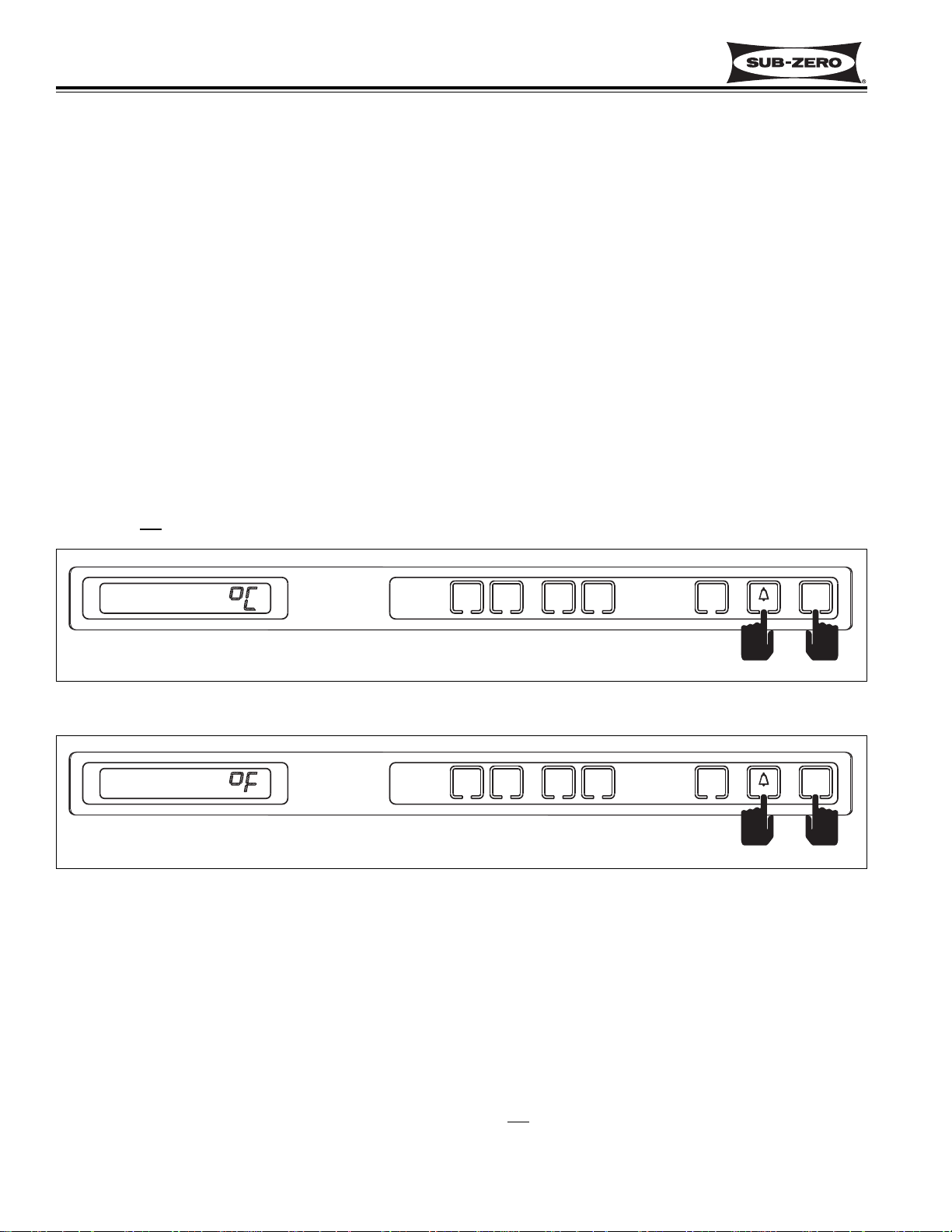
Temperature Units Selection Mode (Selecting Degrees Fahrenheit or Degrees Celsius Display)
700-2 electronic controls are initially set to display temperature in Fahrenheit (°F) units of measure. However, the
temperature units displayed can be converted from °F to °C (Celsius), and/or back again. This operation is called
Temperature Units Selection.
NOTE: Temperature Units Selection must be performed within the first minute after switching the unit ON.
To convert the temperature units of measure from Fahrenheit (°F) readings to Celsius (°C) readings, press and hold
the door ajar alarm bell key and the UNIT ON/OFF key simultaneously for five seconds, then release both keys (See
Figure 3-20). Then, “ °C “ will appear on the LCD indicating that temperatures will now be displayed in Celsius
units of measure. To convert back to Fahrenheit units of measure, repeat pressing the door ajar alarm bell key and
the UNIT ON/OFF key simultaneously (See Figure 3-21).
NOTE: Temperature Units Selection Mode will end ten seconds after the last key stroke.
NOTE: Do not
press and hold the UNIT ON/OFF key first, this will simply switch the unit OFF.
UNIT
ICE
WARMER
COLDER
REFRIGERATOR
ON/OFF
ON/OFF
ON/OFF
WARMER
COLDER
FREEZER
Figure 3-21. Converting Back to Fahrenheit Units of Measure
(within ten seconds of previous key stroke and/or within first minute after switching unit ON)
Press and Hold the Door Ajar Alarm Bell Key and The UNIT ON/OFF Keys
UNIT
ICE
WARMER
COLDER
REFRIGERATOR
ON/OFF
ON/OFF
ON/OFF
WARMER
COLDER
FREEZER
Figure 3-20. Converting to Celsius Units of Measure (within first minute after switching unit ON)
Press and Hold the Door Ajar Alarm Bell Key and The UNIT ON/OFF Keys for Five Seconds
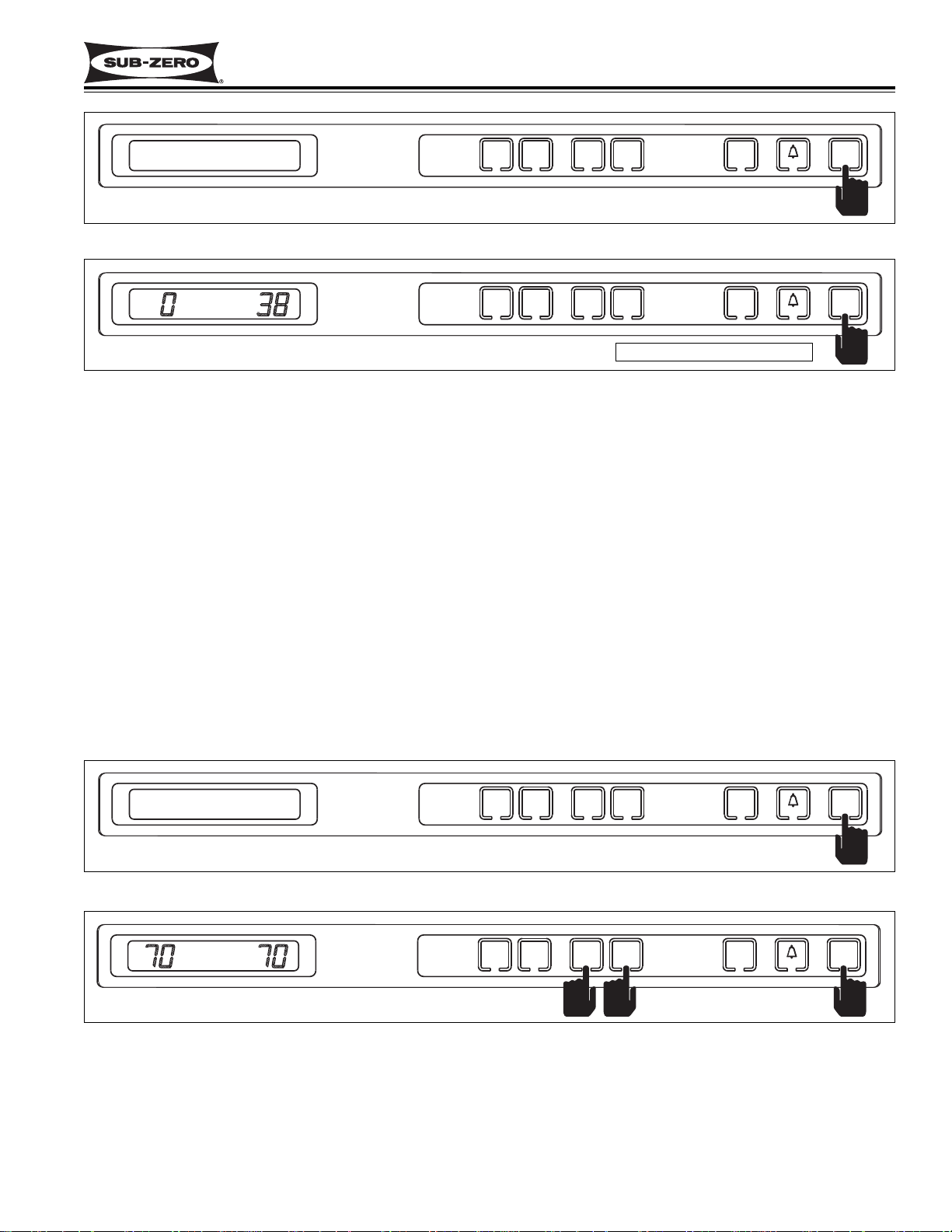
Sabbath Mode
Sabbath Mode was incorporated into the 700-2 electronic control system for the observance of certain religious
days. Initiating Sabbath Mode disables the light switches and the circuits to the ice making system. The door ajar
alarm is also disabled when the unit is in Sabbath Mode.
To initiate Sabbath Mode, the unit must first be switched OFF using the UNIT ON/OFF key (See Figure 3-22). With
the unit switched OFF, press and hold the UNIT ON/OFF key for ten
seconds, then release (See Figure 3-23).
To return to normal lighting operation, press and release the UNIT ON/OFF key.
WARMER
FREEZER
COLDER
WARMER
COLDER
REFRIGERATOR
ICE
ON/OFF
FREEZER
COLDER
WARMER
COLDER
WARMER
REFRIGERATOR
ICE
ON/OFF
ON/OFF
ON/OFF
UNIT
ON/OFF
UNIT
ON/OFF
Page 27
Electronic Control
Integrated (
Integrated (
700-
700-
2) Series
2) Series
3-17
#3756780 - Revision D - July, 2005
UNIT
ICE
WARMER
COLDER
REFRIGERATOR
ON/OFF
ON/OFF
ON/OFF
WARMER
COLDER
FREEZER
UNIT
ICE
WARMER
COLDER
REFRIGERATOR
ON/OFF
ON/OFF
ON/OFF
WARMER
COLDER
FREEZER
Figure 3-23. After Unit is Switched OFF, Press and Hold the UNIT ON/OFF Key for Ten Seconds
UNIT
ICE
WARMER
COLDER
REFRIGERATOR
ON/OFF
ON/OFF
ON/OFF
WARMER
COLDER
FREEZER
OFF
Figure 3-22. To Enter Sabbath Mode, Switch Unit OFF First
Showroom Mode
Showroom Mode was incorporated into the 700-2 electronic control system so that Integrated 700-2 Series units
could be displayed in a showroom setting. When in Showroom Mode, all cooling functions are disabled, but the
lighting system remains active.
To initiate Showroom Mode, the unit must first be switched OFF using the UNIT ON/OFF key. (See Figure 3-24)
With the unit switched OFF, press and hold either pair of WARMER and COLDER keys, then press the UNIT
ON/OFF key, then release all three keys. (See Figure 3-25)
To return unit to normal operating condition, repeat the steps of switching the unit OFF first. Then, press and hold
the WARMER and COLDER keys, then press the UNIT ON/OFF key.
NOTE: Always recheck set-points after returning unit to normal operating condition.
NOTE: It is possible to determine if a unit is in Showroom Mode by initiating Diagnostic Mode. If “Sr” is observed in
the left temperature display area during Diagnostic Mode, the unit is in Showroom mode. Initiating Diagnostic Mode
is covered later in this section.
Figure 3-25. After Unit is Switched OFF, Press and Hold the WARMER and COLDER Keys,
Then Press the UNIT ON/OFF Key
Figure 3-24. To Enter (or Exit) Showroom Mode, Switch Unit OFF First
UNIT
ICE
WARMER
COLDER
REFRIGERATOR
ON/OFF
ON/OFF
ON/OFF
WARMER
COLDER
FREEZER
OFF
Press and hold for 10 seconds
OFF
FREEZER
COLDER
WARMER
COLDER
WARMER
REFRIGERATOR
ICE
ON/OFF
ON/OFF
UNIT
ON/OFF
FREEZER
COLDER
WARMER
WARMER
COLDER
REFRIGERATOR
ICE
ON/OFF
ON/OFF
UNIT
ON/OFF
OFF
FREEZER
COLDER
WARMER
COLDER
WARMER
REFRIGERATOR
ICE
ON/OFF
ON/OFF
UNIT
ON/OFF
FREEZER
COLDER
WARMER
COLDER
WARMER
REFRIGERATOR
ICE
ON/OFF
ON/OFF
UNIT
ON/OFF
Page 28
Electronic Control
Integrated (
Integrated (
700-
700-
2) Series
2) Series
3-18
#3756780 - Revision D - July, 2005
Manual Compartment Disable Mode
The Manual Compartment Disable Mode allows a customer to switch one compartment off for interior cleaning purposes, while allowing the other compartment to continue cooling. A service technician may also find this feature
helpful for service purposes.
To initiate Manual Compartment Disable Mode, the unit must first be switched OFF using the UNIT ON/OFF key
(See Figure 3-26). With the unit switched OFF, press and hold the WARMER key for the compartment being dis-
abled, then press the UNIT ON/OFF key, then release both keys (See Figure 3-27). The LCD will display “- -” (double dashes) in place of temperature readings for the compartment chosen, indicating that all cooling functions for
that compartment are disabled.
To return unit to normal operating condition, repeat the steps of switching the unit OFF first. Then, press and hold
the WARMER key for the disabled compartment, then press the UNIT ON/OFF key.
NOTE: Always recheck set-points after returning unit to normal operating condition.
UNIT
ICE
WARMER
COLDER
REFRIGERATOR
ON/OFF
ON/OFF
ON/OFF
WARMER
COLDER
FREEZER
Figure 3-27. After Unit is Switched OFF, Press and Hold the WARMER Key for the Compartment Being
Disabled, Then Press the UNIT ON/OFF Key.
Figure 3-26. To Enter (or Exit) Manual Compartment Disable Mode, Switch Unit OFF First
Indicating that all cooling functions
for that compartment are disabled.
Manual Freezer Evaporator Defrost
Manual Freezer Evaporator Defrost was incorporated into the Integrated 700-2 Series electronic control to assist in
servicing and problem diagnostics.
To manually initiate freezer evaporator defrost, press and hold the ICE key at the control panel for five seconds, then
release the key. (See Figure 3-28).
NOTE: Manual Freezer Evaporator Defrost will not operate if unit is in Sabbath Mode.
Figure 3-28. Initiate Manual Freezer Evaporator Defrost - Press and Hold the ICE key for Five Seconds
UNIT
ICE
WARMER
COLDER
REFRIGERATOR
ON/OFF
ON/OFF
ON/OFF
WARMER
COLDER
FREEZER
OFF
ICE
UNIT
ICE
WARMER
COLDER
REFRIGERATOR
ON/OFF
ON/OFF
ON/OFF
WARMER
COLDER
FREEZER
Press and hold for 5 seconds
OFF
FREEZER
COLDER
WARMER
COLDER
WARMER
REFRIGERATOR
ICE
ON/OFF
ON/OFF
UNIT
ON/OFF
UNIT
ON/OFF
FREEZER
COLDER
WARMER
COLDER
WARMER
REFRIGERATOR
ICE
ON/OFF
ON/OFF
ICE
FREEZER
COLDER
WARMER
WARMER
COLDER
REFRIGERATOR
ICE
ON/OFF
ON/OFF
UNIT
ON/OFF
Page 29
Electronic Control
Integrated (
Integrated (
700-
700-
2) Series
2) Series
3-19
#3756780 - Revision D - July, 2005
Figure 3-31. Model 700TC/I-2
“ICE” & “SERVICE” Flashing = Water Valve Solenoid energized 15 Seconds, Icemaker System Disabled
NOTE: To clear this error indicator the problem must be corrected, then the unit switched OFF and back ON.
UNIT
ICE
WARMER
COLDER
REFRIGERATOR
ON/OFF
ON/OFF
ON/OFF
WARMER
COLDER
FREEZER
SERVICE
Figure 3-29. Model 700TC/I-2
“EE” Displayed at Left and “SERVICE” Flashing = Freezer Compartment Thermistor (or its Wiring) Fault
NOTE: To clear this error indicator the problem must be corrected
UNIT
ICE
WARMER
COLDER
REFRIGERATOR
ON/OFF
ON/OFF
ON/OFF
WARMER
COLDER
FREEZER
SERVICE
Figure 3-30. Model 700TC/I-2
“EE” Displayed at Right and “SERVICE” Flashing = Refrig. Compartment Thermistor (or its Wiring) Fault
NOTE: To clear this error indicator the problem must be corrected
ICE
UNIT
ICE
WARMER
COLDER
REFRIGERATOR
ON/OFF
ON/OFF
ON/OFF
WARMER
COLDER
FREEZER
SERVICE
UNIT
ICE
WARMER
COLDER
REFRIGERATOR
ON/OFF
ON/OFF
ON/OFF
WARMER
COLDER
FREEZER
SERVICE
Figure 3-32. Model 700TC/I-2
“SERVICE” Alone Flashing = Excessive Compressor Run (OR) Refrig. Evap. Thermistor (or its Wiring) Fault
NOTE: To help identify the problem, Diagnostic Mode (Covered later in this section) should be initiated.
NOTE: To clear this error indicator the problem must be corrected, then the unit switched OFF and back ON.
POSSIBLE 700-2 TALL UNIT ERROR INDICATORS
The next few pages contain diagrams illustrating what a customer may see on the LCD if there is a problem/error
with the unit. Please note the serial number breaks listed under some diagrams.
• For Model 700TC/I-2, See Figures 3-29 through 3-33
• For Model 700TR-2, See Figures 3-34 through 3-37
• For Model 700TF/I-2 and Model 700TF/I-2V, See Figures 3-38 through 3-41
Figure 3-33. Model 700TC/I-2 (AFTER SERIAL #1759493)
“EC” at Right and “SERVICE” Flashing = Excessive Compressor Run with Error Codes Registered
NOTE: To clear this error indicator and error code, the problem must be corrected, then the alarm bell ON/OFF
key must be pressed and held for 15 seconds.
SERVICE
FREEZER
COLDER
WARMER
COLDER
WARMER
REFRIGERATOR
ICE
ON/OFF
ON/OFF
UNIT
ON/OFF
SERVICE
FREEZER
COLDER
WARMER
COLDER
WARMER
REFRIGERATOR
ICE
ON/OFF
ON/OFF
UNIT
ON/OFF
ICE
SERVICE
FREEZER
COLDER
WARMER
COLDER
WARMER
REFRIGERATOR
ICE
ON/OFF
ON/OFF
UNIT
ON/OFF
SERVICE
FREEZER
COLDER
WARMER
COLDER
WARMER
REFRIGERATOR
ICE
ON/OFF
ON/OFF
UNIT
ON/OFF
SERVICE
FREEZER
WARMERCOLDER
WARMERCOLDER
REFRIGERATOR
ON/OFF
ON/OFF
UNITICE
ON/OFF
Page 30
Electronic Control
Integrated (
Integrated (
700-
700-
2) Series
2) Series
3-20
#3756780 - Revision D - July, 2005
UNIT
WARMER
COLDER
DOOR
ON/OFF
ON/OFF
WARMER
COLDER
DRAWERS
SERVICE
Figure 3-35. Model 700TR-2
“EE” Displayed at Right and “SERVICE” Flashing = Upper Compartment Thermistor (or its Wiring) Fault
NOTE: To clear this error indicator the problem must be corrected
UNIT
WARMER
COLDER
DOOR
ON/OFF
ON/OFF
WARMER
COLDER
DRAWERS
SERVICE
Figure 3-36. Model 700TR-2
“SERVICE” Alone Flashing = Excessive Compressor Run (OR)
Upper or Lower Evap. Thermistor (or its Wiring) Fault
NOTE: To help identify the problem, Diagnostic Mode (Covered later in this section) should be initiated.
NOTE: To clear this error indicator the problem must be corrected, then the unit switched OFF and back ON.
UNIT
WARMER
COLDER
DOOR
ON/OFF
ON/OFF
WARMER
COLDER
DRAWERS
SERVICE
Figure 3-34. Model 700TR-2
“EE” Displayed at Left and “SERVICE” Flashing = Lower Compartment Thermistor (or its Wiring) Fault
NOTE: To clear this error indicator the problem must be corrected
WARMER
COLDER
DOOR
WARMER
COLDER
DRAWERS
Figure 3-37. Model 700TR-2 (AFTER SERIAL #1759163)
“EC” at Right and “SERVICE” Flashing = Excessive Compressor Run with Error Codes Registered
NOTE: To clear this error indicator and error code, the problem must be corrected, then the alarm bell ON/OFF
key must be pressed and held for 15 seconds.
SERVICE
DRAWERS
COLDER
WARMER
COLDER
WARMER
DOOR
ON/OFF
UNIT
ON/OFF
SERVICE
DRAWERS
COLDER
WARMER
COLDER
WARMER
DOOR
ON/OFF
UNIT
ON/OFF
SERVICE
DRAWERS
COLDER
WARMER
COLDER
WARMER
DOOR
ON/OFF
UNIT
ON/OFF
SERVICE
DRAWERS
COLDER
WARMER
COLDER
WARMER
DOOR
ON/OFF
UNIT
ON/OFF
Page 31

Electronic Control
Integrated (
Integrated (
700-
700-
2) Series
2) Series
3-21
#3756780 - Revision D - July, 2005
ICE
UNIT
ICE
ON/OFF
ON/OFF
ON/OFF
WARMER
COLDER
FREEZER
SERVICE
Figure 3-39. Model 700TF/I-2 & 700TF/I-2V
“ICE” & “SERVICE” Flashing = Water Valve Solenoid energized 15 Seconds, Icemaker System Disabled
NOTE: To clear this error indicator the problem must be corrected, then the unit switched OFF and back ON.
UNIT
ICE
ON/OFF
ON/OFF
ON/OFF
WARMER
COLDER
FREEZER
SERVICE
Figure 3-38. Model 700TF/I-2 & 700TF/I-2V
“EE” Displayed and “SERVICE” Flashing = Compartment Thermistor (or its Wiring) Fault
NOTE: To clear this error indicator the problem must be corrected
UNIT
ICE
ON/OFF
ON/OFF
ON/OFF
WARMER
COLDER
FREEZER
SERVICE
Figure 3-40. Model 700TF/I-2 & 700TF/I-2V
(700TF/I-2) “SERVICE” Alone Flashing = Excessive Compressor Run
(700TF/I-2V) “SERVICE” Alone Flashing = Excessive High-Speed Commands to Variable Speed Compressor
NOTE: To clear this error indicator the problem must be corrected, then the unit switched OFF and back ON.
UNIT
ICE
ON/OFF
ON/OFF
ON/OFF
WARMER
COLDER
FREEZER
Figure 3-41. Model 700TF/I-2 & 700TF/I-2V (AFTER SERIAL #1757258)
(700TF/I-2) “EC” at Right & “SERVICE” Flashing = Excessive Compressor Run with Error Codes
(700TF/I-2V) “EC” at Right & “SERVICE” Flashing = Excessive High-Speed Commands to Variable Speed
Compressor with Error Codes
NOTE: To clear this error indicator and error code, the problem must be corrected, then the alarm bell ON/OFF
key must be pressed and held for 15 seconds.
SERVICE
FREEZER
COLDER
WARMER
ICE
ON/OFF
ON/OFF
UNIT
ON/OFF
ICE
SERVICE
FREEZER
COLDER
WARMER
ICE
ON/OFF
ON/OFF
UNIT
ON/OFF
SERVICE
FREEZER
COLDER
WARMER
ICE
ON/OFF
ON/OFF
UNIT
ON/OFF
SERVICE
FREEZER
COLDER
WARMER
ICE
ON/OFF
ON/OFF
UNIT
ON/OFF
Page 32

Electronic Control
Integrated (
Integrated (
700-
700-
2) Series
2) Series
3-22
#3756780 - Revision D - July, 2005
700-2 TALL UNIT ELECTRONIC CONTROL TROUBLESHOOTING INPUT OPERATIONS
The following few pages explain troubleshooting input operations performed at the 700-2 tall unit control panel. The
input operations described are Diagnostic Mode, Manual Component Activation Mode and Temperature Log Recall.
Diagnostic Mode
Initiating Diagnostic Mode allows the Service Technician to observe real-time temperature readings from all thermistors without temperature averaging.
NOTE: The models 700TF/I-2 & 700TF/I-2V have only one compartment thermistor and one evaporator thermistor.
NOTE: Since Diagnostic Mode varies only slightly between the different models, a diagram of the 700TC/I-2 control
panel is used to illustrate Diagnostic Mode key strokes.
To initiate Diagnostic Mode, the unit must be ON. With the unit ON, press and hold either
COLDER key, then press
the UNIT ON/OFF key, then release both keys (See Figure 3-42). The left display area will show the real-time temperature of the thermistor being read, the right display area will show the thermistor location code, and all annunciators will illuminate on the LCD indicating the unit is in Diagnostic Mode. Pressing either
COLDER key while in
Diagnostic Mode will toggle to the next thermistor location. (See Figure 3-43, 3-44, 3-45 below and thermistor loca-
tion code tables on next page)
NOTE: After serial #1759493 (700TC/I-2), #1759163 (700TR-2) and #1757258 (700TF/I-2 & 700TF/I-2V), it is also
possible to toggle through the thermistor locations using the WARMER keys.
NOTE: After serial #1759493 (700TC/I-2), #1759163 (700TR-2) and #1757258 (700TF/I-2 & 700TF/I-2V), If the
COLDER and UNIT ON/OFF keys are pressed and held for 10 seconds, Manual Component Activation Mode will be
initiated (this is covered later in the section).
NOTE: Diagnostic Mode will end 20 seconds after the last key stroke.
Figure 3-42. Initiate Diagnostic Mode - Press and Hold Either COLDER Key, Then the UNIT ON/OFF Key
(“F” Indicates Freezer Compartment)
Figure 3-43. Toggle Through Temperature Readings - Press Either COLDER Key
(“r” Indicates Refrigerator Compartment)
Figure 3-44. Toggle Through Temperature Readings - Press Either COLDER Key
(“FE” Indicates Freezer Evaporator)
Figure 3-45. Toggle Through Temperature Readings - Press Either
COLDER Key
(“rE” Indicates Refrigerator Evaporator)
ICE
SERVICE
OFF
FREEZER
WARMERCOLDER
WARMERCOLDER
REFRIGERATOR
ON/OFF
ON/OFF
UNITICE
ON/OFF
ICE
SERVICE
OFF
FREEZER
WARMERCOLDER
WARMERCOLDER
REFRIGERATOR
ON/OFF
ON/OFF
UNITICE
ON/OFF
SERVICE
ICE
OFF
SERVICE
ICE
OFF
FREEZER
WARMERCOLDER
WARMERCOLDER
FREEZER
WARMERCOLDER
WARMERCOLDER
REFRIGERATOR
REFRIGERATOR
ON/OFF
ON/OFF
ON/OFF
ON/OFF
UNITICE
ON/OFF
UNITICE
ON/OFF
Page 33

Electronic Control
Integrated (
Integrated (
700-
700-
2) Series
2) Series
3-23
#3756780 - Revision D - July, 2005
UNIT
ICE
WARMER
COLDER
REFRIGERATOR
ON/OFF
ON/OFF
ON/OFF
WARMER
COLDER
FREEZER
ICE
SERVICE
OFF
UNIT
ICE
WARMER
COLDER
REFRIGERATOR
ON/OFF
ON/OFF
ON/OFF
WARMER
COLDER
FREEZER
ICE
SERVICE
OFF
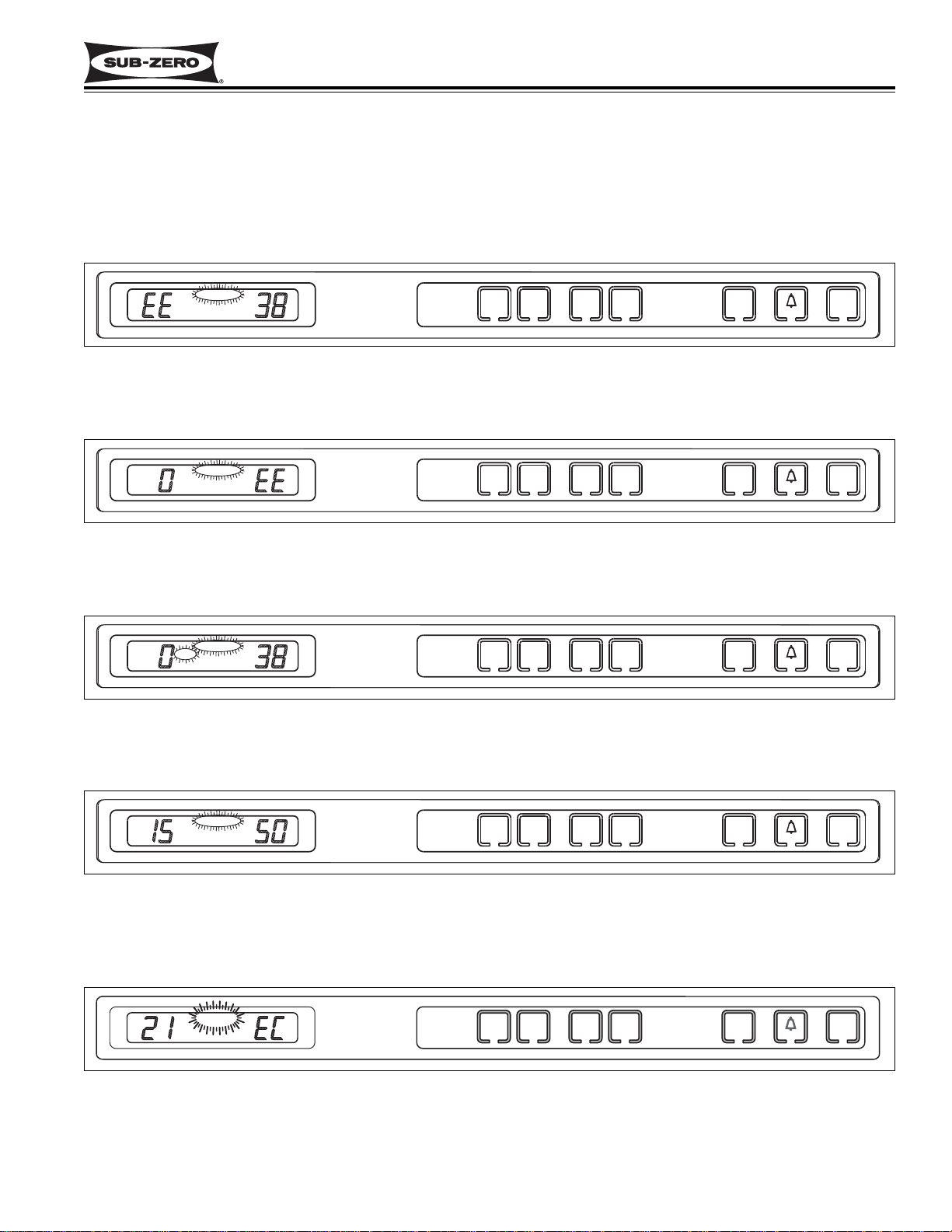
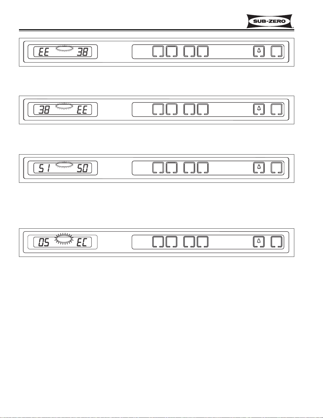
Figure 3-46. “EE” Observed in Diagnostic Mode = Thermistor Fault in Location Indicated by Code
Figure 3-47. “Sr” Observed While in Diagnostic Mode = Unit is in Showroom Mode
If “EE” is observed in left display area during Diagnostic Mode, the thermistor in that location is open or shorted, or
there is a break in that thermistor’s wiring (See Figure 3-46).
If “Sr” is observed at left display area during Diagnostic Mode, the unit is in Showroom Mode, which was explained
earlier in this section (See Figure 3-47).
ICE
UNIT
ICE
ON/OFF
ON/OFF
ON/OFF
WARMER
COLDER
FREEZER
SERVICE
OFF
Figure 3-48. (700TF/I-2V Only) “SP” Observed While in Diagnostic Mode = Compressor Speed Command
If “SP” is observed in right display area during Diagnostic Mode, this indicates the speed commands being sent from
the microprocessor to the compressor controller. This will only appear in the model 700TF/I-2V. (See Figure 3-48).
NOTE: Speed commands display as: “00” = 0 RPM, “16” = 1600 RPM, “17” = 1700 RPM, “18” = 1800 RPM, “21” =
2100 RPM, “22” = 2200 RPM, “24” = 2400 RPM and “27” = 2700 RPM, “36” = 3600 RPM and “40” = 4000 RPM
After serial #1759493 (700TC/I-2), #1759163 (700TR-2) and #1757258 (700TF/I-2 & 700TF/I-2V), If “EC” is
observed in the right display area during Diagnostic Mode, the numbers at left are “Error Codes” (See Figure 3-49
and the Error Code Table on next page). Error Codes indicate problems registered by specific components. If error
codes are registered, they will appear before temperature readings and can be toggled through with the temperature
readings as described on the previous page.
Figure 3-49. “EC” Observed While in Diagnostic Mode = Error Code (See Table on Following Page)
700TC/I-2
THERMISTOR LOCATION CODE
Freezer Compartment F
Refrigerator Compartment r
Freezer Evaporator FE
Refrigerator Evaporator rE
700TR-2
THERMISTOR LOCATION CODE
Lower Compartment L
Upper Compartment U
Lower Evaporator LE
Upper Evaporator UE
700TF/I-2
THERMISTOR LOCATION CODE
Freezer Compartment F
Freezer Evaporator FE
700TF/I-2V
THERMISTOR LOCATION CODE
Compressor Speed SP
Freezer Compartment F
Freezer Evaporator FE
ICE
SERVICE
OFF
FREEZER
COLDER
WARMER
COLDER
WARMER
REFRIGERATOR
ICE
ON/OFF
ON/OFF
UNIT
ON/OFF
ICE
SERVICE
OFF
FREEZER
COLDER
WARMER
COLDER
WARMER
REFRIGERATOR
ICE
ON/OFF
ON/OFF
UNIT
ON/OFF
ICE
SERVICE
OFF
FREEZER
COLDER
WARMER
ICE
ON/OFF
ON/OFF
UNIT
ON/OFF
ICE
SERVICE
OFF
FREEZER
WARMERCOLDER
WARMERCOLDER
REFRIGERATOR
ON/OFF
ON/OFF
UNITICE
ON/OFF
Page 34

Electronic Control
Integrated (
Integrated (
700-
700-
2) Series
2) Series
3-24
#3756780 - Revision D - July, 2005
Error Code Table
CODE INDICATION
05 Refrig. cabinet thermistor read open or shorted for 10+ seconds, or repeatedly read erratic temp’s
06 Refrig. evaporator thermistor read open or shorted for 10+ seconds, or repeatedly read erratic temp’s
07 Freezer cabinet thermistor read open or shorted for 10+ seconds, or repeatedly read erratic temp’s
08 Freezer evaporator thermistor read open or shorted for 10+ seconds, or repeatedly read erratic temp’s
20 Defrost under-heat with no voltage feedback through Gray/White wire at defrost start
21 Defrost overheat
22 No voltage feedback through Gray/White wire at defrost start
23 Defrost overheat with no voltage feedback through Gray/White wire at defrost start
24 Defrost under-heat
80 High VS compressor differential pressure or low voltage supplied to VS compressor
81 High amperage draw at VS compressor
82 VS compressor could not maintain lowest minimum speed at highest current draw
83 Locked VS compressor rotor
84 Short circuit at VS compressor controller output circuit
85 VS compressor converter overheated and shut down VS compressor
86 Serial communication failure between VS compressor controller and electronic control board
.
87 Speed information from electronic control board is out of specification
88 Electronic control board not receiving status data in response to speed commands
If error codes are observed during Diagnostic Mode, a non-flashing SERVICE annunciator will appear on the LCD
when Diagnostic Mode ends, indicating error codes are still registered (See Figure 3-50). To clear a non-flashing
SERVICE annunciator and the error codes, the problem must be corrected and the unit must be ON. Then, the Bell
ON/OFF key must be pressed and held for fifteen seconds. The control will emit a short “beep” when the SERVICE
annunciator and error codes are cleared. (See Figure 3-51)
Figure 3-51. Clear Non-flashing SERVICE Annunciator - Press & Hold Bell ON/OFF Key for 15 Seconds
Figure 3-50. Non-flashing SERVICE Annunciator after Diagnostic Mode = Error Codes were Registered
Press and hold for 15 seconds
NOTE: Error Codes were incorporated into the electronic control system after serial #1759493 (700TC/I-2),
#1759163 (700TR-2) and #1757258 (700TF/I-2 & 700TF/I-2V). The Error Code table below only applies to units
after these serial numbers.
NOTE: VS compressor = Variable Speed compressor
NOTE: Currently, Error Codes are registered because of thermistor errors, defrost system errors or 700TF/I-2V vari-
able speed compressor control system errors. The table above will be updated through addendums when subsequent software and electrical changes occur and more error codes are added. See paragraph below for instructions
on how to clear Error Codes.
SERVICE
FREEZER
WARMERCOLDER
WARMERCOLDER
REFRIGERATOR
ON/OFF
ON/OFF
UNITICE
ON/OFF
UNITICE
ON/OFF
BEEP!
FREEZER
WARMERCOLDER
WARMERCOLDER
REFRIGERATOR
ON/OFF
ON/OFF
Page 35

Electronic Control
Integrated (
Integrated (
700-
700-
2) Series
2) Series
3-25
#3756780 - Revision D - July, 2005
Figure 3-52. Initiate Manual Component Activation Mode -
Press and Hold Desired COLDER Key and UNIT ON/OFF Key for 10 Seconds
Manual Component Activation Mode
After serial #1759493 (700TC/I-2), #1759163 (700TR-2) and #1757258 (700TF/I-2 & 700TF/I-2V), a Manual
Component Activation Mode was added to the electronic control system. Manual Component Activation Mode
allows a Service Technician to energize a cooling system for five minutes. When activated, the chosen compartment’s compressor and evaporator fan are energized along with the condenser fan. While in Component Activation
Mode, the evaporator temperatures for that compartment are displayed on the LCD. This also allows the Service
Technician to check for proper voltage readings at the activated components without having to wait for the compartment to call for cooling.
To initiate Manual Component Activation Mode, the unit must be ON. With the unit ON, press and hold the desired
compartment COLDER key and the UNIT ON/OFF key for ten seconds (See Figure 3-52). The evaporator temperature for that compartment will be displayed in the left display area of the LCD and the right display area will show the
thermistor location.
NOTE: If the COLDER and UNIT ON/OFF keys are pressed and held for less then 10 seconds, Diagnostic Mode
will be initiated. This was covered earlier in the section.
NOTE: It is possible to toggle through the the other temperature readings as in Diagnostic Mode, but in this case
the temperature readings will last for five minutes rather than twenty seconds.
NOTE: The compressor overload could prevent the compressor from energizing.
NOTE: Manual Component Activation Mode will end five minutes after it is initiated. It is possible to end this five
minute run time and return to normal operation by switching the unit OFF then back ON. If this is done, note that
the electronic control will observe a three minute minimum compressor OFF time when the unit is switched back
ON. This is to protect the compressor and its electricals.
Press and hold for 10 seconds
ICE
SERVICE
OFF
FREEZER
WARMERCOLDER
WARMERCOLDER
REFRIGERATOR
ON/OFF
ON/OFF
UNITICE
ON/OFF
Page 36

Electronic Control
Integrated (
Integrated (
700-
700-
2) Series
2) Series
3-26
#3756780 - Revision D - July, 2005
Temperature Log Recall Mode
The electronic control system is equipped with a temperature history data storage system. This system logs/stores
the average temperature of each individual thermistor every two hours (rounded to the nearest two degrees), along
with any event indicators (explained later in this section), that may have occurred. These two-hour periods are
referred to as “indexes”. Up to 168 indexes can be stored for each compartment, making it possible to observe the
preceding fourteen days of the unit’s temperature history (each index equals 2 hour temperature average; 2 hours X
168 indexes = 14 days). After 168 indexes are stored, each new index will bump the oldest index. Index number “1”
being the most recent two-hour temperature average and index number “168” being the oldest. Accessing this temperature history data so it can be viewed on the LCD is accomplished by initiating Temperature Log Recall Mode.
There are two ways to initiate Temperature Log Recall Mode. One allows viewing of compartment temperature history only (see below), the other allows viewing of compartment temperature history and evaporator temperature history (see following page).
NOTE: Temperature Log Recall mode as described on the following page is only possible after serial #1759493
(700TC/I-2), #1759163 (700TR-2) and #1757258 (700TF/I-2 & 700TF/I-2V).
Initiate Temperature Log Recall Mode To View Compartment Temperature History Only - Begin with the unit
ON. Now, press and hold the desired compartment WARMER key, then press the UNIT ON/OFF key, then release
both keys (See Figure 3-53). The left display area on the LCD will show average compartment thermistor temperature and in the right display area will be the index number. The first index number will be “1”, indicating the most
recent two-hour temperature average. The right display area will also flash the thermistor location code at three
second intervals (See Figure 3-54).
Figure 3-53. Initiate Temperature Log Recall Mode To View Compartment Temperature History Only -
Press and Hold Desired WARMER Key, Then Press UNIT ON/OFF Key
Figure 3-54. Thermistor Location Code Flashes Every Three Seconds
Figure 3-55. Toggle Up Through Indexes - Press WARMER Key in Consecutive Key Strokes
Figure 3-56. Toggle Down Through Indexes - Press COLDER Key in Consecutive Key Strokes
To toggle up through the indexes (from 1 to 168), press the same WARMER key in multiple key strokes (See Figure
3-55). To toggle down through the indexes (from 168 to 1), press the corresponding COLDER key in multiple key
strokes (See Figure 3-56).
FREEZER
WARMERCOLDER
WARMERCOLDER
REFRIGERATOR
ON/OFF
ON/OFF
UNITICE
ON/OFF
FREEZER
WARMERCOLDER
WARMERCOLDER
REFRIGERATOR
ON/OFF
ON/OFF
UNITICE
ON/OFF
FREEZER
WARMERCOLDER
WARMERCOLDER
REFRIGERATOR
ON/OFF
ON/OFF
UNITICE
ON/OFF
FREEZER
WARMERCOLDER
WARMERCOLDER
REFRIGERATOR
ON/OFF
ON/OFF
UNITICE
ON/OFF
Page 37

Electronic Control
Integrated (
Integrated (
700-
700-
2) Series
2) Series
3-27
#3756780 - Revision D - July, 2005
Figure 3-59. Initiate Temperature Log Recall Mode To View Temperature History -
Press and Hold Desired
WARMER Key and UNIT ON/OFF Key
Figure 3-57. Initiate Diagnostic Mode - Press and Hold Either COLDER Key, then the UNIT ON/OFF Key
Figure 3-58. Toggle Through Temperature Readings - Press Either COLDER Key or Either WARMER Key
Until Desired Thermistor Temperature is Displayed
Initiate Temperature Log Recall Mode To View Compartment and Evaporator Temperature History - After
serial #1759493 (700TC/I-2), #1759163 (700TR-2) and #1757258 (700TF/I-2 & 700TF/I-2V) Temperature Log Recall
Mode was expanded to include the average evaporator temperatures. To view evaporator temperatures as well as
the compartment temperatures, begin with the unit ON and in Diagnostic Mode (See Figure 3-57). While in
Diagnostic Mode, toggle through the readings until the desired thermistor temperature is displayed on the LCD (See
Figure 3-58). Now, press the WARMER key for that compartment and the UNIT ON/OFF key simultaneously (See
Figure 3-59). The left display area on the LCD will show average thermistor temperature and in the right display area
will be the index number “1” indicating the most recent two-hour temperature average (See Figure 3-59). The right
display area will also flash the thermistor location code at three second intervals (See Figure 3-60).
To toggle up through the indexes (from 1 to 168), press the same WARMER key in multiple key strokes (See Figure
3-61). To toggle down through the indexes (from 168 to 1), press the corresponding COLDER key in multiple key
strokes (See Figure 3-62).
Figure 3-60. Thermistor Location Code Flashes Every Three Seconds
Figure 3-61. Toggle Up Through Indexes - Press WARMER Key in Consecutive Key Strokes
Figure 3-62. Toggle Down Through Indexes - Press COLDER Key in Consecutive Key Strokes
ICE
SERVICE
OFF
FREEZER
WARMERCOLDER
WARMERCOLDER
REFRIGERATOR
ON/OFF
ON/OFF
UNITICE
ON/OFF
ICE
SERVICE
OFF
FREEZER
WARMERCOLDER
WARMERCOLDER
REFRIGERATOR
ON/OFF
ON/OFF
UNITICE
ON/OFF
FREEZER
WARMERCOLDER
WARMERCOLDER
REFRIGERATOR
ON/OFF
ON/OFF
UNITICE
ON/OFF
FREEZER
WARMERCOLDER
WARMERCOLDER
REFRIGERATOR
ON/OFF
ON/OFF
UNITICE
ON/OFF
FREEZER
WARMERCOLDER
WARMERCOLDER
REFRIGERATOR
ON/OFF
ON/OFF
UNITICE
ON/OFF
FREEZER
WARMERCOLDER
WARMERCOLDER
REFRIGERATOR
ON/OFF
ON/OFF
UNITICE
ON/OFF
Page 38

Electronic Control
Integrated (
Integrated (
700-
700-
2) Series
2) Series
3-28
#3756780 - Revision D - July, 2005
Figure 3-64. SERVICE Annunciator Illuminates - Indicates Unit was switched OFF During that Index Period
by Pressing UNIT ON/OFF Key
Figure 3-65. Bell Illuminates - Indicates Power Failure / Interruption During that Index Period
Figure 3-66. Double Dashes ( - - ) Displayed Instead of Temperature for Several Consecutive Index Periods -
Indicates Bad EEPROM on Control Board. Board Must be Replaced
NOTE: Double dashes will also be observed when in Manual Compartment Disable Mode. Only when double
dashes are observed in Temperature Log Recall Mode for several consecutive indexes
should the control board be
replaced.
NOTE: If Manual Compartment Disable Mode has been activated during any of the 168 indexes, average tempera-
tures will continue to be logged. No event indicator will appear with these temperatures.
NOTE: If the unit was in Showroom Mode during any of the 168 indexes, average temperatures will continue to be
logged. No event indicator will appear with these temperatures.
NOTE: If the unit was switched OFF by pressing the UNIT ON/OFF key during any of the 168 indexes and there
was still 115V AC supplied to the control board, the average temperatures will continue to be logged. This means
temperatures would be expected to rise and the SERVICE annunciator would be present in all indexes in which the
unit was OFF.
NOTE: Temperature Log Recall Mode will end 20 seconds after the last key stroke.
Possible Event Indicators During Temperature Log Recall Mode(s)
The diagrams below illustrate possible event indicators that may be observed while in Temperature Log Recall
Mode. (See Figures 3-63 through 3-66)
Figure 3-63. “bl” Indicates Index is “blank” - No Temperature has Been Logged Yet
(Only possible within first 14 days of unit operation, or after new control board is installed during service)
FREEZER
WARMERCOLDER
WARMERCOLDER
REFRIGERATOR
ON/OFF
ON/OFF
UNITICE
ON/OFF
SERVICE
FREEZER
WARMERCOLDER
WARMERCOLDER
REFRIGERATOR
ON/OFF
ON/OFF
UNITICE
ON/OFF
FREEZER
WARMERCOLDER
WARMERCOLDER
REFRIGERATOR
ON/OFF
ON/OFF
UNITICE
ON/OFF
FREEZER
WARMERCOLDER
WARMERCOLDER
REFRIGERATOR
ON/OFF
ON/OFF
UNITICE
ON/OFF
Page 39

Electronic Control
Integrated (
Integrated (
700-
700-
2) Series
2) Series
3-29
#3756780 - Revision D - July, 2005
Index= Hours Past
1 = 2 Hrs
2=4 Hrs
3=6 Hrs
4 = 8Hrs
5 = 10Hrs
6 = 12 Hrs
7 = 14 Hrs
8 = 16 Hrs
9 = 18 Hrs
10 = 20 Hrs
11 = 22 Hrs
12 = 24 Hrs (1 Day)
13 = 26 Hrs
14 = 28 Hrs
15 = 30 Hrs
16 = 32 Hrs
17 = 34 Hrs
18 = 36 Hrs
19 = 38 Hrs
20 = 40 Hrs
21 = 42 Hrs
22 = 44 Hrs
23 = 46 Hrs
24 = 48 Hrs (2 Days)
25 = 50 Hrs
26 = 52 Hrs
27 = 54 Hrs
28 = 56 Hrs
29 = 58 Hrs
30 = 60 Hrs
31 = 62 Hrs
32 = 64 Hrs
33 = 66 Hrs
34 = 68 Hrs
35 = 70 Hrs
36 = 72 Hrs (3 Days)
37 = 74 Hrs
38 = 76 Hrs
39 = 78 Hrs
40 = 80 Hrs
41 = 82 Hrs
42 = 84 Hrs
Index= Hours Past
43 = 86 Hrs
44 = 88 Hrs
45 = 90 Hrs
46 = 92 Hrs
47 = 94 Hrs
48 = 96 Hrs (4 Days)
49 = 98 Hrs
50 = 100 Hrs
51 = 102 Hrs
52 = 104 Hrs
53 = 106 Hrs
54 = 108 Hrs
55 = 110 Hrs
56 = 112 Hrs
57 = 114 Hrs
58 = 116 Hrs
59 = 118 Hrs
60 = 120 Hrs (5 Days)
61 = 122 Hrs
62 = 124 Hrs
63 = 126 Hrs
64 = 128 Hrs
65 = 130 Hrs
66 = 132 Hrs
67 = 134 Hrs
68 = 136 Hrs
69 = 138 Hrs
70 = 140 Hrs
71 = 142 Hrs
72 = 144 Hrs (6 Days)
73 = 146 Hrs
74 = 148 Hrs
75 = 150 Hrs
76 = 152 Hrs
77 = 154 Hrs
78 = 156 Hrs
79 = 158 Hrs
80 = 160 Hrs
81 = 162 Hrs
82 = 164 Hrs
83 = 166 Hrs
84 = 168 Hrs (7 Days)
Index= Hours Past
85 = 170 Hrs
86 = 172 Hrs
87 = 174 Hrs
88 = 176 Hrs
89 = 178 Hrs
90 = 180 Hrs
91 = 182 Hrs
92 = 184 Hrs
93 = 186 Hrs
94 = 188 Hrs
95 = 190 Hrs
96 = 192 Hrs (8 Days)
97 = 194 Hrs
98 = 196 Hrs
99 = 198 Hrs
100 = 200 Hrs
101 = 202 Hrs
102 = 204 Hrs
103 = 206 Hrs
104 = 208 Hrs
105 = 210 Hrs
106 = 202 Hrs
107 = 214 Hrs
108 = 216 Hrs (9 Days)
109 = 218 Hrs
110 = 220 Hrs
111 = 222 Hrs
112 = 224 Hrs
113 = 226 Hrs
114 = 228 Hrs
115 = 230 Hrs
116 = 232 Hrs
117 = 234 Hrs
118 = 236 Hrs
119 = 238 hrs
120 = 240 Hrs (10 Days)
121 = 242 Hrs
122 = 244 Hrs
123 = 246 Hrs
124 = 248 Hrs
125 = 250 Hrs
126 = 252 Hrs
Index= Hours Past
127 = 254 Hrs
128 = 256 Hrs
129 = 258 Hrs
130 = 260 Hrs
131 = 262 Hrs
132 = 264 Hrs (11 Days)
133 = 266 Hrs
134 = 268 Hrs
135 = 270 hrs
136 = 272 Hrs
137 = 274 Hrs
138 = 276 Hrs
139 = 278 Hrs
140 = 280 Hrs
141 = 282 Hrs
142 = 284 Hrs
143 = 286 Hrs
144 = 288 Hrs (12 Days)
145 = 290 Hrs
146 = 292 Hrs
147 = 294 Hrs
148 = 296 Hrs
149 = 298 Hrs
150 = 300 Hrs
151 = 302 Hrs
152 = 304 Hrs
153 = 306 Hrs
154 = 308 Hrs
155 = 310 Hrs
156 = 312 Hrs (13 Days)
157 = 314 Hrs
158 = 316 Hrs
159 = 318 Hrs
160 = 320 Hrs
161 = 322 Hrs
162 = 324 Hrs
163 = 326 hrs
164 = 328 Hrs
165 = 330 Hrs
166 = 332 Hrs
167 = 334 Hrs
168 = 336 Hrs (14 Days)
Temperature Log Index Chart
NOTE : The chart below applies to the hours in which the control has power. Temperature history data will only be
stored when the control has 115V AC supplied to it. If power to the unit is interrupted, the average temperatures for
that time period are stored with the event indicator. The temperature history data is stored in a non-volatile memory,
so the data is not erased by a power failure, but actual time passage during the power failure will not be shown.
TEMPERATURE LOG INDEX CHART
Page 40

Electronic Control
Integrated (
Integrated (
700-
700-
2) Series
2) Series
3-30
#3756780 - Revision D - July, 2005
Figure 3-67. Basic 700-2 Base Unit Electronic Control System Diagram
BASIC 700- 2 BASE UNIT ELECTRONIC CONTROL SYSTEM
Input operations for the electronic control system are performed at the control panel (located inside the upper drawer), with monitoring, regulating and controlling functions taking place at the control board (located in the sump area).
Temperatures and possible problems with the unit are displayed in the control panel on the LCD. This page illustrates a basic 700-2 base unit electronic control system. (See Figure 3-67) The entire electronic control system is
described in greater detail on the following pages.
CONTROL PANEL ASSEMBLY
LCD
BAFFLE CONTROL
(BR-2 Only)
ICEMAKER SWITCH
ICEMAKER
(BF/I-2 Only)
FREEZER
WARMER
COLDER
CONTROL BOARD
(BF/I-2 Only)
LIGHTS
ICE
ON/OFF
UNIT
ON/OFF
ON/OFF
UPPER
COMPARTMENT
THERMISTOR
DRAWER SWITCH
(UPPER)
LOWER
COMPARTMENT
THERMISTOR
(BR-2 Only)
DRAWER SWITCH
(LOWER)
EVAP THERMISTOR
NEUT
115 VOLTS
60 CYCLES
EVAP FAN
DEFROST TERMINATOR
WATER
SOLENOID
(BF/I-2 Only)
DEFROST HEATER (BF/I-2 Only)
(BF/I-2 Only)
COMPRESSOR
L1
COND FAN
Page 41

Electronic Control
Integrated (
Integrated (
700-
700-
2) Series
2) Series
3-31
#3756780 - Revision D - July, 2005
Figure 3-68. 700-2 Base Unit Control Board Layout
Figure 3-69. 700-2 Base Unit Control Board Summary Table (700BF/I-2 Summary Table Shown)
700-2 BASE UNIT CONTROL BOARD LAYOUT AND SUMMARY TABLE
The electrical connection points on the 700-2 base unit control board are labeled alphanumerically. These labels
correspond with the alphanumeric control board summary table, located on all 700 Series wiring diagrams. By referencing the summary table, it is possible to identify which components are connected at which points on the control
board. Below is a layout diagram of the control board, and a copy of a summary table. (See Figures 3-68 & 3-69)
NOTE: All components on the control board are non-replaceable. If a problem with the control board is identified,
the complete control board must be replaced.
TERM.
P1
P2
P3
P4
P5
P6
P7
P8
P9
P10
P11
P12
P13
P14
P11
1
P10
P7
P9
P8
P14
P6
P5
TEST
DESCRIPTION
THERMISTORS
LIGHT SWITCH
REMOTE DISPLAY
BAFFLES
L2-NEUTRAL 115 WHITE
L1-HOT 115
LIGHTS-115V OUT
DEFROST HEATER
EVAPORATOR FAN
ICEMAKER SWITCH
JUMPER
------
-----COMPRESSOR
MANUFACTURING TEST
COLOR
SEE AUX. CHART ----WHITE/RED
SEE AUX. CHART
-----WHITE
BLACK
ORANGE
BLUE
RED
PINK
BLACK
------
-----PURPLE
------
ABBR.
WH/RD
-----
-----
BLACK
ORANG
BLUE
RED
PINK
BLACK
-----
----PURPLE
TESTP15
1
P4P2 P3
REMOTE
DISPLAY
ZONE
THERMISTORS
P15
P1
TERM.
P1
P3 1
No#
2
3
4
5
6
7
8
2
3
4
5
6
AUXILIARY CHART
1
11
COLOR
EMPTY
1
EMPTY
BLUE W/RED
BLUE W/RED
LT. BLUE W/YELLOW
LT. BLUE W/YELLOW
BLUE W/BLACK
BLUE W/BLACK
BLACK
WHITE
RED
YELLOW
ORANGE
BLUE
Page 42

Electronic Control
Integrated (
Integrated (
700-
700-
2) Series
2) Series
3-32
#3756780 - Revision D - July, 2005
SERVICE
OFF
700-2 BASE UNIT CONTROL PANEL LAYOUT
Please note that in the second part of this section the illustrations of the control panel will vary between the 700BR-2
and the 700BF/I-2, depending on the topic covered. (See Figure 3-70 & 3-71)
NOTE: The LCD on the Integrated 700-2 Series base units is not back lit by unit lighting. It will appear darker than
the LCD on Integrated 700-2 Series tall units.
Figure 3-70. 700BR-2 Control Panel Layout
UNIT
ON/OFF
KEY
DRAWER
AJAR
ALARM
ON/OFF
KEY
UPPER DRAWER
SET-POINT
ADJUSTMENT
KEYS
LOWER DRAWER
SET-POINT
ADJUSTMENT
KEYS
LCD
Liquid
Crystal
Display
Figure 3-71. 700BF/I-2 Control Panel Layout
ICE
SERVICE
OFF
UNIT
ON/OFF
KEY
DRAWER
AJAR
ALARM
ON/OFF
KEY
ICEMAKER SYSTEM
ON/OFF
KEY
SET-POINT
ADJUSTMENT
KEYS
LCD
Liquid
Crystal
Display
SERVICE
Jake Dog was here
OFF
LOWER
DRAWER
COLDER
WARMER
UPPER
DRAWER
COLDER
WARMER
ON/OFF
UNIT
ON/OFF
SERVICE
ICE
Jake Dog was here
OFF
FREEZER
WARMER
COLDER
ON/OFF
ICE
ON/OFF
UNIT
ON/OFF
Page 43

Electronic Control
Integrated (
Integrated (
700-
700-
2) Series
2) Series
3-33
#3756780 - Revision D - July, 2005
WHEN IN OFF MODE, 115 VOLTS AC IS STILL PRESENT AT CONTROL BOARD.
Figure 3-72. 700-2 Base Unit ON/OFF, Press UNIT ON/OFF Key
BASIC 700-2 BASE UNIT ELECTRONIC CONTROL INPUT OPERATIONS
The following illustrations show the basic input operations performed at the 700-2 base unit control panel. Switching
the unit ON and OFF, adjusting the set-point (temperature adjustments), switching the ice maker system ON and
OFF (700BFI-2 only), and enabling and disabling the door ajar alarm feature will be explained.
Unit ON/OFF
All units are shipped in the Off Mode and when power is supplied to the unit, a trace of the word “OFF” is visible on
the LCD. By pressing and releasing the UNIT ON/OFF key (See Figure 3-72), power is allowed past the control
board to the rest of the unit. This will be indicated by the unit lights illuminating and the LCD energizing.
NOTE: Whenever the unit is switched off
using the the UNIT ON/OFF key, a trace of the word “OFF” will be visible
on the LCD as long as there is power to the unit.
Adjusting Set-Point (Temperature Adjustments)
To adjust the set-points, press the appropriate compartment WARMER or COLDER key on the control panel in multi
ple key strokes until the desired set-point is achieved. One key stroke equals a one degree (Fahrenheit or Celsius)
change. (See Figure 3-73)
NOTE: Temperature ranges are -5°F (-21°C) to +5°F (-15°C) in freezer compartment, with an initial set-point of
0°F (-18°C), and +34°F (+1°C) to +45°F (+7°C) in refrigerator compartment, with an initial set-point of +38°F (+3°C).
NOTE: The initial key stroke of the WARMER or COLDER keys will change the previous set-point by one degree
(Fahrenheit or Celsius).
NOTE: The set-point will be displayed on the LCD for 10 seconds after the last WARMER or COLDER key stroke.
After the 10 second delay, the compartment temperature will be displayed. As the compartment temperature
changes, the temperature displayed on the LCD will change by no more than one degree per minute.
Figure 3-73. Adjusting the Set-Point - Press WARMER or COLDER Key In Multiple Key Strokes
LOWER
DRAWER
COLDER
WARMER
UPPER
DRAWER
COLDER
WARMER
ON/OFF
UNIT
ON/OFF
LOWER
DRAWER
COLDER
WARMER
UPPER
DRAWER
COLDER
WARMER
ON/OFF
UNIT
ON/OFF
Page 44

Electronic Control
Integrated (
Integrated (
700-
700-
2) Series
2) Series
3-34
#3756780 - Revision D - July, 2005
Icemaker System ON/OFF (700BFI-2 Only)
All 700BFI-2 units are shipped with the icemaker system switched of
f. By pressing and releasing the ICE ON/OFF
key on the control panel, power is allowed to the icemaker system, and “ICE” appears on the LCD (See Figure 3-
75). To disable the icemaker system, press and release the ICE ON/OFF key again and “ICE” will disappear from
the LCD indicating the icemaker system is off.
NOTE: When the unit is in “Sabbath Mode,” the icemaker system is de-energized. Sabbath Mode will be explained
in UNIQUE ELECTRONIC CONTROL SYSTEM INPUT OPERATIONS.
NOTE: Unlike the 700-2 tall units, there is not a 45 minute dwell after an ice harvest in a 700BF/I-2 unit. The ice-
maker water valve is also not monitored by the control board.
Figure 3-75. 700BFI-2 Icemaker System ON/OFF - Press ICE ON/OFF Key
ICE
Drawer Ajar Alarm ON/OFF
All Integrated 700-2 Series base units are equipped with a drawer ajar alarm feature. When activated the alarm will
alert a customer if a drawer is stuck open or accidentally left open. To enable the drawer ajar alarm feature, press
and release the drawer ajar alarm bell ON/OFF key on the control panel. A bell annunciator will appear on the LCD
indicating that the alarm feature is active. (See Figure 3-74) Now, if a drawer is open for 30 seconds, the bell
annunciator will blink and the audible alarm will beep. To disable the drawer ajar alarm, simply press the drawer ajar
alarm bell ON/OFF key and the bell annunciator on the LCD will disappear, indicating the alarm feature is of
f.
Figure 3-74. Drawer Ajar Alarm ON/OFF, Press Alarm Bell ON/OFF Key
LOWER
DRAWER
COLDER
WARMER
UPPER
DRAWER
COLDER
WARMER
ON/OFF
UNIT
ON/OFF
ICE
COLDER
WARMER
FREEZER
ICE
ON/OFF
ON/OFF
UNIT
ON/OFF
Page 45

Electronic Control
Integrated (
Integrated (
700-
700-
2) Series
2) Series
3-35
#3756780 - Revision D - July, 2005
FUNCTIONS OF 700 BASE UNIT ELECTRONIC CONTROL SYSTEM
The following few pages explain the monitoring, regulating and controlling functions of the electronic control system.
Signal trace schematics illustrations are used to demonstrate current flow for the function being explained.
NOTE: Only normal operating electronic control functions are described along with problems which could cause
error annunciators. All possible malfunctions are addressed in the Troubleshooting Guide.
Supply Power to the Lighting System
115 Volts are supplied to the lighting system through the control board when the unit is switched on
by pressing the
UNIT ON/OFF key and a drawer is opened (See Figure 3-76).
NOTE: Disabling the lighting system (Sabbath Mode) is covered in UNIQUE ELECTRONIC CONTROL SYSTEM
INPUT OPERATIONS.
Figure 3-76. Signal Trace Schematic (High Voltage) of Lighting System
When a drawer is opened, 115 Volts are
supplied to lighting system unless unit is
switched OFF or is in Sabbath Mode
HIGH VOLTAGE
115 VOLTS
60 CYCLES
BLACK
L1
NEUTRAL
WHITE
WHITE
M
MAIN BOARD
M
ORANGE
TOP DRAWER
LIGHT
LOWER DRAWER
LIGHT
M
Page 46

Electronic Control
Integrated (
Integrated (
700-
700-
2) Series
2) Series
3-36
#3756780 - Revision D - July, 2005
Monitor, Regulate and Display Two Separate Compartment Temperatures in the 700BR-2
Figure 3-77. Signal Trace Schematic (High & Low Voltage)
of Model 700BR-2 with Both Compartments Calling for Cooling
Figure 3-78. Average Refrigerator Compartment Temperatures Displayed
Upper and lower compartments calling for
cooling. Upper Thermistor controls compressor. Lower Thermistor controls air babble.
Evap fan, compressor and
condenser fan energized
Air baffle open
By using an electronically controlled air
baffle, it is possible to adjust the set-point
in the lower drawer of a 700BR-2 a maximum of three degrees colder than the
upper drawer.
Power to the compressor and condenser
fan in a 700BR-2 is controlled by the thermistor located inside the upper reed
switch. When the upper drawer compartment temperature reaches high offset, the
control board energizes the evaporator
fan, compressor and condenser fan. (See
Figure 3-77) When the low offset temper-
ature is achieved in the upper drawer, the
control board de-energizes the evaporator
fan, compressor and condenser fan.
If the lower drawer compartment temperature (sensed by the thermistor in the lower
reed switch) is at high offset when the
refrigeration system is running, the air baffle will be energized to open. (See Figure
3-77) When the temperature in the lower
drawer reaches low offset, the air baffle is
closed.
Though the compartment air temperatures
will fluctuate, the LCD displays the average compartment temperatures (See
Figure 3-78).
NOTE: If the temperature in the lower
compartment rises five degrees above its
high offset and the upper compartment is
not calling for cooling, the air baffle will
open and the evaporator fan will be energized, but the compressor and condenser
fan will remain off
. The air baffle will
remain open until both compartments are
equal in temperature.
NOTE: If the compartment temperature
should ever exceed either the high offset
or low offset (example: when a door is left
open), the temperature displayed on the
LCD will change by one degree per
minute.
LOW VOLTAGE
BAFFLE
LOWER DRAWER
HIGH VOLTAGE
BLACK
DISPLAY BOARD
THERMISTOR
LOWER DRAWER
THERMISTOR
TOP DRAWER
115 VOLTS
60 CYCLES
L1
NEUTRAL
MAIN BOARD
MAIN BOARD
YELLOW W/WHITE
YELLOW W/RED
YELLOW W/BLACK
BLUE W/RED
BLUE W/RED
BLUE W/YELLOW
BLUE W/YELLOW
WHITE
WHITE
RED
PURPLE
OVERLOAD
PROTECTOR
M
EVAPORATOR FAN MOTOR
COMPRESSOR
M
CONDENSER FAN
COMPRESSOR
STARTING
RELAY
M
LOWER
DRAWER
COLDER
WARMER
UPPER
DRAWER
COLDER
WARMER
ON/OFF
UNIT
ON/OFF
Page 47

Electronic Control
Integrated (
Integrated (
700-
700-
2) Series
2) Series
3-37
#3756780 - Revision D - July, 2005
Figure 3-80. Average Freezer Compartment Temperature Displayed
Figure 3-79. Signal Trace Schematic (High & Low Voltage) of
700BF/I-2 Calling for Cooling
The two drawers of the 700BF/I-2 are considered one compartment/zone. It is not
possible to set two different set-points for
the individual drawers.
The temperature signal from the thermistor in the upper reed switch is monitored
by the microprocessor, and displayed on
the LCD. Though the compartment air
temperature does fluctuate, the LCD displays the average temperature (See
Figure 3-80). When the compartment
temperature reaches high offset, the
microprocessor supplies power to the
evaporator fan, compressor and condenser fan. (See Figure 3-79). When the
compartment temperature reaches low offset, the microprocessor interrupts power
to the compressor and evaporator fan,
cycling them of
f.
NOTE: If the compartment temperature
should ever exceed either the high offset
or low offset (example: when a door is left
open), the temperature displayed on the
LCD will change by one degree per
minute.
High offset temperature
detected
Evap fan, compressor and
condenser fan energized
Monitor, Regulate and Display Temperatures in the 700BF/I-2
LOW VOLTAGE SCHEMATIC
DISPLAY BOARD
THERMISTOR
TOP DRAWER
HIGH VOLTAGE SCHEMATIC
BLACK
MAIN BOARD
115 VOLTS
60 CYCLES
L1
NEUTRAL
RED
PURPLE
LT. BLUE W/YELLOW
LT. BLUE W/YELLOW
M
EVAPORATOR FAN MOTOR
OVERLOAD
PROTECTOR
COMPRESSOR
M
RUNNING
CAPACITOR
COMPRESSOR
STARTING
RELAY
MAIN BOARD
WHITE
WHITE
M
CONDENSER FAN
COLDER
WARMER
FREEZER
ICE
ON/OFF
ON/OFF
UNIT
ON/OFF
Page 48

Electronic Control
Integrated (
Integrated (
700-
700-
2) Series
2) Series
3-38
#3756780 - Revision D - July, 2005
Monitor and Control Refrigerator Off-Cycle Defrost in the 700BR-2
If the the upper drawer compartment in a 700BR-2 calls for cooling (upper compartment at high offset temperature),
but the temperature sensed by the evaporator thermistor has not reached 38°F (3°C), the evaporator fan will be
energized, but power to the compressor and condenser fan will wait. This allows the refrigerator evaporator to fully
defrost before the compressor and condenser fan are energized. (See Figure 3-81)
Figure 3-81. Signal Trace Schematic (High & Low Voltage) of Model 700BR-2 Refrigerator Off-Cycle Defrost
1. High offset
temperature
detected
2. Evaporator temp
below 38°F (3°C)
3. Evap fan
energized
4. Compressor &
Condenser
fan wait until
evap rises to
38°F (3°C)
LOW VOLTAGE
MAIN BOARD
DISPLAY BOARD
BLUE W/RED
BLUE W/RED
BLUE W/YELLOW
BLUE W/YELLOW
BLUE W/BLACK
BLUE W/BLACK
THERMISTOR
LOWER DRAWER
HIGH VOLTAGE
BLACK
THERMISTOR
TOP DRAWER
THERMISTOR
EVAPORATOR
115 VOLTS
60 CYCLES
L1
MAIN BOARD
NEUTRAL
RED
EVAPORATOR FAN MOTOR
OVERLOAD
PROTECTOR
M
COMPRESSOR
M
CONDENSER FAN
COMPRESSOR
STARTING
RELAY
M
WHITE
WHITE
Page 49

Electronic Control
Integrated (
Integrated (
700-
700-
2) Series
2) Series
3-39
#3756780 - Revision D - July, 2005
Initially, the freezer compressor will cyclerun for twelve hours, after which the
microprocessor sends the signal to the
defrost relay on the control board to close.
This supplies power to the defrost heater,
and the compressor is switched off. With
the “Adaptive Defrost” technique, the
length of time that the heater stays on to
heat the evaporator to 52°F is observed
by the microprocessor via the evaporator
thermistor.
NOTE: The defrost terminator in a
700BF/I-2 is there only to prevent the
defrost heater from staying energized too
long, in the event of an evaporator thermistor failure.
The microprocessor then determines the
number of hours before the next defrost.
If the heater stays on for a shorter time
than specified, the microprocessor
increases the next defrost interval. If the
heater stays on longer than specified, the
electronic control decreases the next
defrost interval. (See Figure 3-82) This is
an ongoing process whereby the defrost
time and the defrost interval will vary by
unit use.
NOTE: A five minute time delay/dwell fol-
lows all defrosts. At the end of the five
minute dwell, the compressor is energized, but the evaporator fan will not be
energized until the evaporator temperature
falls below 35°F (2°C).
NOTE: The minimum defrost interval is six
hours; the maximum defrost interval is
forty-two hours; the maximum defrost
duration is twenty minutes.
Figure 3-82. Signal Trace Schematic (High & Low Voltage)
of Model 700BF/I-2 Freezer Adaptive Defrost
Defrost circuit energized
Timeframe for
evap to reach
52°F observed via
evap thermistor
Monitor and Control “Adaptive Defrost” in the 700BF/I-2
LOW VOLTAGE SCHEMATIC
DISPLAY BOARD
THERMISTOR
EVAPORATOR
HIGH VOLTAGE SCHEMATIC
BLACK
MAIN BOARD
115 VOLTS
60 CYCLES
L1
NEUTRAL
RED
BLUE W/BLACK
BLUE W/BLACK
M
MAIN BOARD
WHITE
WHITE
M
M
DEFROST
TERMINATOR
GRAY
DRAIN HEATER
FILL TUBE HEATER
DEFROST HEATER
25 - 29 OHMS
1700 - 2100 OHMS
2300 -2900 OHMS
Page 50

Electronic Control
Integrated (
Integrated (
700-
700-
2) Series
2) Series
3-40
#3756780 - Revision D - July, 2005
UNIQUE 700- 2 BASE UNIT ELECTRONIC CONTROL INPUT OPERATIONS
The following pages illustrate unique 700-2 base unit electronic control input operations performed at the control
panel that you would not expect a customer to perform every day. The following input operations described are
Temperature Unit Selection Mode, Sabbath Mode, Showroom Mode and Manual Freezer Evaporator Defrost.
Temperature Units Selection Mode (Selecting Degrees Fahrenheit or Degrees Celsius Display)
The electronic control is initially set to display temperature in Fahrenheit (°F) units of measure. Units of measure
can be converted from °F to °C (Celsius), and/or back again. This operation is called Temperature Units Selection.
NOTE: Temperature Units Selection must be performed within the first minute after switching the unit ON..
To convert the temperature units of measure from Fahrenheit (°F) readings to a Celsius (°C) readings, press and
hold the door ajar alarm bell key and the UNIT ON/OFF key simultaneously for five seconds, then release the keys.
(See Figure 3-83) “°C“ will appear on the LCD indicating that temperatures will now be displayed in Celsius units of
measure. To convert back to Fahrenheit units of measure, repeat the steps above.
NOTE: Temperature Units Selection Mode will end ten seconds after the last key stroke.
Figure 3-83. Converting Units of Measure (within first minute after switching unit ON)
Press and Hold the Door Ajar Alarm Bell Key and The UNIT ON/OFF Key for Five Seconds
Sabbath Mode
Sabbath Mode was incorporated into the 700-2 electronic control system for the observance of certain religious
days. Initiating Sabbath Mode disables the light switches and the circuits to the ice making system The door ajar
alarm is also disabled when the unit is in Sabbath Mode.
To initiate Sabbath Mode, the unit must first be switched OFF using the UNIT ON/OFF key (See Figure 3-84). With
the unit switched OFF, press and hold the UNIT ON/OFF key for ten
seconds, then release (See Figure 3-85).
To return to normal lighting operation, press and release the UNIT ON/OFF key.
Figure 3-85. After Unit is Switched OFF, Press and Hold the UNIT ON/OFF Key for Ten Seconds
OFF
Figure 3-84. To Enter Sabbath Mode, Switch Unit OFF First
Press and hold for 10 seconds
LOWER
DRAWER
COLDER
WARMER
UPPER
DRAWER
COLDER
WARMER
ON/OFF
UNIT
ON/OFF
OFF
LOWER
DRAWER
COLDER
WARMER
UPPER
DRAWER
COLDER
WARMER
ON/OFF
UNIT
ON/OFF
LOWER
DRAWER
COLDER
WARMER
UPPER
DRAWER
COLDER
WARMER
ON/OFF
UNIT
ON/OFF
Page 51

Electronic Control
Integrated (
Integrated (
700-
700-
2) Series
2) Series
3-41
#3756780 - Revision D - July, 2005
Showroom Mode
Showroom Mode was incorporated into the 700-2 electronic control system so that Integrated 700-2 Series units
could be displayed in a showroom setting. When in Showroom Mode, all cooling functions are disabled, but the
lighting system remains active.
To initiate Showroom Mode, the unit must first be switched OFF using the UNIT ON/OFF key (See Figure 3-86).
With the unit switched OFF, press and hold the WARMER and COLDER keys, then press the UNIT ON/OFF key,
then release all three keys (See Figure 3-87).
To return unit to normal operating condition, repeat the steps above.
NOTE: Always recheck set-points after returning unit to normal operating condition.
NOTE: Unlike the 700-2 tall units, it is not
possible to determine if a base unit is in Showroom Mode by initiating
Diagnostic Mode and looking for “Sr”.
- To determine if a 700BF/I-2 unit is in Showroom Mode, press the ICE key on the control panel and listen for the
relay on the control board to “click.” If a “click” is not heard, the unit is in Showroom Mode.
- To determine if a 700BR-2 unit is in Showroom Mode, open both drawers to warm the compartments, adjust setpoints to 34°F (1°C) and listen for the compressor and condenser fan to energize. Due to the three minute minimum-off time, and depending on how cold the compartments are, this may take several minutes to verify.
Figure 3-87. After Unit is Switched OFF, Press and Hold the WARMER and COLDER Keys,
Then Press the UNIT ON/OFF Key
Figure 3-86. To Enter (or Exit) Showroom Mode, Switch Unit OFF First
OFF
Manual Freezer Evaporator Defrost (700BF/I-2 Only)
Manual Freezer Evaporator Defrost was incorporated into the 700BF/I-2 electronic control to assist in servicing and
diagnosing.
To manually initiate freezer evaporator defrost, press and hold the ICE key at the control panel for five seconds, then
release the key (See Figure 3-88).
NOTE: Manual Freezer Evaporator Defrost will not operate if unit is in Sabbath Mode.
Figure 3-88. Initiate Manual Freezer Evaporator Defrost - Press and Hold the ICE key for Five Seconds
ICE
Press and hold for 5 seconds
OFF
LOWER
DRAWER
COLDER
WARMER
UPPER
DRAWER
COLDER
WARMER
ON/OFF
UNIT
ON/OFF
LOWER
DRAWER
COLDER
WARMER
UPPER
DRAWER
COLDER
WARMER
ON/OFF
UNIT
ON/OFF
ICE
FREEZER
WARMER
COLDER
ICE
ON/OFF
ON/OFF
UNIT
ON/OFF
Page 52

Electronic Control
Integrated (
Integrated (
700-
700-
2) Series
2) Series
3-42
#3756780 - Revision D - July, 2005
POSSIBLE 700-2 BASE UNIT ERROR INDICATORS
This page contains diagrams illustrating what customers may see on the LCD if a problem/error exists with the unit.
(For Model 700BR-2, see Figures 3-89 through 3-93. For Model 700BF/I-2, see Figures 3-92 through 3-94.)
NOTE: A blinking “SERVICE” annunciator in a base unit indicates thermistor faults only
. Unlike the tall units, the
blinking “SERVICE” annunciator cannot indicate excessive compressor run, because the length of compressor runtime is not monitored on base units.
NOTE: Unlike the 700-2 tall units, the “SERVICE” and “ICE” annunciators on the LCD of a 700BFI-2 will not blink,
and the ice making system will not be disabled, if the water valve is energized for more than 15 seconds.
NOTE: To clear thermistor error indicators, the problem must be corrected.
Figure 3-90. For Model 700BR-2
“EE” Displayed at Right and “SERVICE” Flashing = Upper Compartment Thermistor (or its Wiring) Fault
Figure 3-89. For Model 700BR-2
“EE” Displayed at Left and “SERVICE” Flashing = Lower Compartment Thermistor (or its Wiring) Fault
Figure 3-91. For Model 700BR-2
“SERVICE” Blinking = Evaporator Thermistor Fault or Break in Thermistor Wiring
SERVICE
SERVICE
SERVICE
SERVICE
Figure 3-94. For Model 700BF/I-2
“EE” Displayed at Left and “SERVICE” Flashing = Freezer Compartment Thermistor (or its Wiring) Fault
Figure 3-93. For Model 700BR-2 & 700BF/I-2
“E3” Displayed = Communication Error Between Control Board and Control Panel
Figure 3-92. For Model 700BR-2 & 700BF/I-2
“E0” Displayed = Communication Error Between Control Board and Control Panel
SERVICE
LOWER
DRAWER
COLDER
WARMER
UPPER
DRAWER
COLDER
WARMER
ON/OFF
UNIT
ON/OFF
SERVICE
LOWER
DRAWER
COLDER
WARMER
UPPER
DRAWER
COLDER
WARMER
ON/OFF
UNIT
ON/OFF
SERVICE
LOWER
DRAWER
COLDER
WARMER
UPPER
DRAWER
COLDER
WARMER
ON/OFF
UNIT
ON/OFF
LOWER
DRAWER
COLDER
WARMER
UPPER
DRAWER
COLDER
WARMER
ON/OFF
UNIT
ON/OFF
LOWER
DRAWER
COLDER
WARMER
UPPER
DRAWER
COLDER
WARMER
ON/OFF
UNIT
ON/OFF
SERVICE
COLDER
WARMER
FREEZER
ICE
ON/OFF
ON/OFF
UNIT
ON/OFF
Page 53

Electronic Control
Integrated (
Integrated (
700-
700-
2) Series
2) Series
3-43
#3756780 - Revision D - July, 2005
SERVICE
OFF
SERVICE
OFF
700-2 BASE UNIT ELECTRONIC CONTROL TROUBLESHOOTING INPUT OPERATIONS
This page illustrates 700-2 base unit troubleshooting input operations performed at the control panel, which at this
writing is only Diagnostic Mode.
Diagnostic Mode
Diagnostic Mode allows the service technician to observe real-time temperature readings from the thermistors in
both compartments and at both evaporators without off-set adjustments or temperature averaging.
NOTE: There is only one compartment thermistor and one evaporator thermistor in the model 700BF/I-2.
NOTE: Since the Diagnostic Mode varies only slightly between the 700BR-2 and 700BF/I-2, a diagram of the
700BR-2 control panel is used to illustrate Diagnostic Mode key strokes.
To initiate Diagnostic Mode, the unit must be ON. With the unit ON, press and hold either
COLDER key, then press
the UNIT ON/OFF key, then release both keys. The left temperature display area indicates the real-time temperature of the first thermistor being read. The left temperature display area shows a code which indicates the location
of the thermistor, and all annunciators illuminate on the LCD indicating the unit is in Diagnostic Mode (See Figure 3-
95 and Thermistor Location Code Tables at bottom of page). Pressing either COLDER key while in Diagnostic Mode
will toggle to the next thermistor location (See Figure 3-96 and Thermistor Location Code Tables at bottom of page).
NOTE: If “EE” is observed in the left temperature display area during Diagnostic Mode, the thermistor in that loca-
tion is defective or there is a break in that thermistor’s wiring.
NOTE: Diagnostic Mode will end twenty seconds after the last key stroke.
Figure 3-95. Initiating Diagnostic Mode
Press and Hold Either COLDER Key, Then Press the UNIT ON/OFF Key
Figure 3-96. Toggling Through Temperature Readings in Diagnostic Mode
Press Either COLDER Key
Base Unit Thermistor Location Code Tables
700BR-2
THERMISTOR LOCATION CODE
Lower Compartment L
Upper Compartment U
Evaporator E
700BF/I-2
THERMISTOR LOCATION CODE
Freezer Compartment F
Evaporator E
SERVICE
OFF
LOWER
DRAWER
COLDER
WARMER
UPPER
DRAWER
COLDER
WARMER
ON/OFF
UNIT
ON/OFF
SERVICE
OFF
LOWER
DRAWER
COLDER
WARMER
UPPER
DRAWER
COLDER
WARMER
ON/OFF
UNIT
ON/OFF
Page 54

Electronic Control
Integrated (
Integrated (
700-
700-
2) Series
2) Series
3-44
#3756780 - Revision D - July, 2005
ADDITIONAL 700-2 BASE UNIT ELECTRONIC CONTROL NOTES
- There is not
a 45 minutes dwell after each ice harvest in the BFI-2.
- The “SERVICE” and “ICE” annunciators on the LCD of a 700BFI-2 will not
blink, and the ice making system will
not be disabled, if the water valve is energized for more than 15 seconds.
- There is not a Manual Compartment Disable Mode in 700-2 base units, because there is only one compressor.
- There is not a Manual Component Activation Mode in 700-2 base units.
- The 700-2 Base unit’s electronic control system does not
have Error Codes.
- There is not
a Temperature Log recall Mode for the 700-2 base units.
Page 55

Sealed System Information
Integrated (
Integrated (
700-
700-
2) Series
2) Series
4-2
#3756780 - Revision D - July, 2005
HFC-134a REFRIGERANT SERVICE INFORMATION
The 700-2 Series sealed systems contain HFC-134a refrigerant. This section provides some general rules for working with 134a, and explains procedures to be followed while servicing the sealed system. This is followed by diagrams which illustrate sealed system operation, then model-specific refrigerant flow diagrams.
134a refrigerant requires Synthetic Ester oil in the compressor, and does not tolerate contamination from
other refrigerants, moisture, petroleum-based lubricants, silicone lubricants, cleaning compounds, rust
inhibitors, leak detection dyes, or any other type of additive.
General Rules for Working with 134a Refrigerant
• Use equipment dedicated to 134a sealed system service only.
• Use only 134a refrigerant for back-flushing and sweep charging.
• Always replace the filter-drier when servicing the sealed system.
• The filter-drier must be cut from the sealed system. Never un-braze the drier as the heat will drive moisture
back into the sealed system.
• Do not leave sealed system nor replacement compressor open to the atmosphere for more than 10 minutes.
• When the rubber plugs are pulled from the service compressor, a release of pressure should be heard. If no
release of pressure is heard, do not use the compressor.
• Use ONLY virgin 134a refrigerant when recharging the sealed system.
Page 56

Sealed System Information
Integrated (
Integrated (
700-
700-
2) Series
2) Series
4-3
#3756780 - Revision D - July, 2005
SEALED SYSTEM REP
SEALED SYSTEM REP
AIR PROCEDURES
AIR PROCEDURES
Service Procedures
a. Capture refrigerant
b. Replace compressor
c. Replace filter-drier
d. Evacuate or sweep charge system
e. Recharge system with Virgin 134a refrigerant
a. Capture refrigerant
b. Repair leak
c. Replace filter-drier
d. Evacuate or sweep charge system
e. Recharge system with Virgin 134a refrigerant
a. Capture refrigerant
b. Repair leak (if at solder joint) or replace part
c. Back flush high side of sealed system
d. If all refrigerant has escaped and system is in a vacuum, replace compressor
e. Replace filter-drier
f. Evacuate or sweep charge system
g. Recharge system with Virgin 134a refrigerant
a. Capture refrigerant
b. Repair leak (if at solder joint) or replace part
c. Back flush high side of sealed system
d. Replace compressor
e. Replace filter-drier
f. Replace heat exchanger if cap tube is clogged
g. Install a low side drier on suction line
h. Evacuate or sweep charge sealed system
i. Recharge with Virgin 134a refrigerant
a. Capture refrigerant
b. Locate and remove restriction or locate and replace part
c. Back flush high side of sealed system
d. Replace filter-drier
e. Evacuate or sweep charge system
f Recharge system with Virgin 134a refrigerant.
a. Capture refrigerant
b. Replace filter-drier
c. Evacuate or sweep charge system
d. Recharge system with Virgin 134a refrigerant
Problem
Non-Operating,
Inefficient, Noisy
Compressor
(NOTE: To check for a
non-operating compressor, a hard start kit can be
used)
High Side leak
Low Side Leak
Contaminated System
Examples:
> Compressor Burn out
> Excessive moisture
from leak in condensate loop or in low side
> Plugged capillary tube
Restriction
(NOTE: If restriction is
due to sealed system
being contaminated, see
Contaminated Sealed
System above.)
Overcharge
Page 57

Sealed System Information
Integrated (
Integrated (
700-
700-
2) Series
2) Series
4-4
#3756780 - Revision D - July, 2005
Figure 4-2. Condenser & Heater Loop
SEALED SYSTEM OPERATION
The six diagrams on these pages illustrate a basic sealed
system. The components are listed in order of refrigerant
flow, with an explanation of their fundamental role as part
of a sealed system. NOTE: These illustrations do not
represent any specific 700-2 sealed system.
Compressor (Figure 4-1)
The compressor creates a high side and low side pressure
difference in the sealed system by compressing the refrigerant gas, thus raising the pressure and temperature. The
compressor pushes this high-pressure/high-heat gas to the
condenser.
Condenser (Figure 4-2)
The high-pressure/high-heat gas travels through the condenser, where the heat is dissipated by cooler air being
drawn over the condenser tubing by the condenser fan.
This changes the gas into a high-pressure/warm liquid that
is then routed through the door gasket seat heater loop to
prevent sweating. After traveling through the heater loop,
the high-pressure/warm liquid enters the high-side filterdrier.
Filter-Drier (Figure 4-3)
The high-pressure/warm liquid travels through the highside filter-drier, which removes moisture from the refrigerant before it enters the capillary tube.
Figure 4-3. Filter-Drier
1
3
2
COMPRESSOR
HEATER LOOP
CONDENSER
FILTER-DRIER
Page 58

Sealed System Information
Integrated (
Integrated (
700-
700-
2) Series
2) Series
4-5
#3756780 - Revision D - July, 2005
Figure 4-5. Evaporator
Capillary Tube (& Heat Exchanger) (Figure 4-4)
The warm liquid refrigerant travels through the long skinny
capillary tube which is soldered to the suction line. (These
two tubes soldered together create the heat exchanger.)
As the warm liquid refrigerant travels through the capillary
tube it gives up heat to the cool refrigerant gas traveling
through the suction line and the pressure drops, so it is a
low-pressure/cool liquid before it enters the evaporator.
Evaporator (Figure 4-5)
As the low-pressure/cool liquid refrigerant enters the evaporator, it vaporizes. This is caused by a dramatic pressure
change which occurs when the refrigerant enters the larger diameter evaporator tubing from the smaller diameter
capillary tubing. This vapor travels through the evaporator
absorbing heat from the compartment, gradually converting it to a cool gas. This cool gas then enters the suction
line.
Suction Line (& Heat Exchanger) (Figure 4-6)
The cool gas travels through the suction line which is soldered to the capillary tube. (As mentioned earlier, these
two tubes soldered together create the heat exchanger.)
As this cool refrigerant gas travels through the suction line
it absorbs heat from the warm liquid refrigerant traveling
through the capillary tube, making it a luke warm gas. The
lukewarm refrigerant gas then returns to the compressor
where the process begins again.
Figure 4-6. Suction Line & Heat Exchanger
Figure 4-4. Capillary Tube (& Heat Exchanger)
5
HEAT EXCHANGER
4
6
CAPILLARY TUBE
EVAPORATOR
HEAT EXCHANGER
SUCTION LINE
Page 59

Sealed System Information
Integrated (
Integrated (
700-
700-
2) Series
2) Series
4-6
#3756780 - Revision D - July, 2005
SEALED SYSTEM REFRIGERANT FLOW DIAGRAMS
Figure 4-7. Model 700TC/I-2 Refrigerant Flow
= REFRIGERATOR SEALED SYSTEM
= FREEZER SEALED SYSTEM
FRAME HEATER (HOT GAS)
REFRIGERATOR HEAT-EXCHANGER
FREEZER HEAT-EXCHANGER
REFRIGERATOR COMPRESSOR
FREEZER COMPRESSOR
REFRIGERATOR EVAPORATOR
FREEZER EVAPORATOR
FREEZER FILTER-DRIER
REFRIGERATOR FILTER-DRIER
CONDENSER
(FRONT - FREEZER)
(BACK - REFRIGERATOR)
Page 60

Sealed System Information
Integrated (
Integrated (
700-
700-
2) Series
2) Series
4-7
#3756780 - Revision D - July, 2005
Figure 4-8. Model 700TR-2 Refrigerant Flow
Figure 4-9. Model 700TF/I-2 and 700TF/I-2V Refrigerant Flow
= UPPER REFRIGERATOR SEALED SYSTEM
= LOWER REFRIGERATOR SEALED SYSTEM
REFRIGERATOR HEAT-EXCHANGER
(UPPER)
FRAME HEATER (HOT GAS)
REFRIGERATOR EVAPORATOR
(UPPER)
REFRIGRATOR HEAT-EXCHANGER
(LOWER)
REFRIGERATOR COMPRESSOR
(UPPER)
REFRIGERATOR COMPRESSOR
(LOWER)
= FREEZER SEALED SYSTEM
REFRIGERATOR EVAPORATOR
(LOWER)
REFRIGERATOR FILTER-DRIER (UPR)
REFRIGERATOR FILTER-DRIER (LWR)
CONDENSER
(FRONT - REFRIGERATOR, LOWER)
(BACK - REFRIGERATOR, UPPER)
FRAME HEATER (HOT GAS)
HEAT-EXCHANGER
COMPRESSOR
EVAPORATOR
FILTER-DRIER
CONDENSER
Page 61

Sealed System Information
Integrated (
Integrated (
700-
700-
2) Series
2) Series
4-8
#3756780 - Revision D - July, 2005
Figure 4-11. Model 700BF/I-2 Refrigerant Flow
Figure 4-10. Model 700BR-2 Refrigerant Flow
= REFRIGERATOR SEALED SYSTEM
EVAPORATOR
(EVAPORATOR SUMP)
HEAT-EXCHANGER
FRAME HEATER (HOT GAS)
FILTER-DRIER
= FREEZER SEALED SYSTEM
(EVAPORATOR SUMP)
COMPRESSOR
EVAPORATOR
CONDENSER
FRAME HEATER (HOT GAS)
HEAT-EXCHANGER
COMPRESSOR
FILTER-DRIER
CONDENSER
Page 62

Airflow & Fan Blade Spacing
Integrated (
Integrated (
700-
700-
2) Series
2) Series
5-3
#3756780 - Revision D - July, 2005
Figure 5-2. 700TR-2 Air Flow and Fan Blade Spacing
Figure 5-3. 700TF/I-2 and 700TF/I-2V Air Flow and Fan Blade Spacing
UPPER FAN MOTOR
Bracket
7/8"
± 1/16"
(2.22 cm ± .16 cm)
3/4"
± 1/16"
(1.91 cm ± .16 cm)
Blade
LOWER FAN MOTOR
Blade
Clamp
Away From
Motor
Bracket
Clamp
Away From
Motor
FAN MOTOR
Bracket
Blade
Prior to Serial #1757258 = 1" ± 1/16"
Starting w/Serial #1757258 =
Clamp
Away From
Motor
(2.54 cm ± .16cm)
1" ± 1/16"
(2.54 cm ± .16cm)
Page 63

Airflow & Fan Blade Spacing
Integrated (
Integrated (
700-
700-
2) Series
2) Series
5-2
#3756780 - Revision D - July, 2005
Figure 5-1. 700TC/I-2 Air Flow and Fan Blade Spacing
UPPER FAN MOTOR
Bracket
7/8"
± 1/16"
(2.22 cm ± .16 cm)
Bracket
Blade
LOWER FAN MOTOR
Clamp
Away From
Motor
Clamp
Away From
Motor
Blade
7/8" ± 1/16"
(2.22 cm ± .16 cm)
Page 64

Airflow & Fan Blade Spacing
Integrated (
Integrated (
700-
700-
2) Series
2) Series
5-4
#3756780 - Revision D - July, 2005
Figure 5-4. 700BR-2 Air Flow and Fan Blade Spacing
Figure 5-5. 700BF/I-2 Air Flow and Fan Blade Spacing
11/16" ± 1/16"
(1.75 cm ± .16 cm)
Blade
Clamp
Towards
Motor
Bracket
11/16" ± 1/16"
(1.75 cm ± .16 cm)
Blade
Clamp
Towards
Motor
Bracket
Page 65

Icemaker Operation
Integrated (
Integrated (
700-
700-
2) Series
2) Series
6-2
#3756780 - Revision D - July, 2005
MODULAR ICEMAKER
All Integrated (700-2) Series units utilize a “modular icemaker”. The icemaker operation is not complex, however, an
understanding of its cycle of operation is necessary in order for a serviceman to make a proper diagnosis.
Modular Icemaker Operation
When the icemaker thermostat has sensed temperatures of 17°F, the thermostat closes. At this time, the current
now has a path through the thermostat to the motor. The motor is linked with the drive gear. From the module,
there are copper contacts that ride on copper strips on the backside of the drive gear. (See Figure 6-1) As the drive
gear rotates, these contacts from the module will make or break a circuit (track) to the copper strips to generate the
icemaker cycle.
Figure 6-1. Modular Icemaker Electrical Schematic
Pink
Tan
Page 66

Icemaker Operation
Integrated (
Integrated (
700-
700-
2) Series
2) Series
6-3
#3756780 - Revision D - July, 2005
Additional Icemaker Operation Notes
NOTE 1: The ICE ON/OFF key at the control panel activates the icemaker system. If “ICE” is not displayed on the
LCD, the icemaker system is OFF.
NOTE 2: To allow ice to freeze fully and reduce effects of low water pressure, the electronic control system disables
the icemaker system for 45 minutes after each ice harvest (this does not
apply to the 700BFI-2). To
bypass the 45 minute dwell, press the ICE key to switch the ice making system OFF, then press the ICE
key again to cycle the ice making system back ON.
NOTE 3: The ice bucket activates a switch when in place. If the ice bucket is not in proper position, ice production
will stop.
NOTE 4: The icemaker shut-off arm must be in the “down / on” position for the icemaker to operate.
NOTE 5: The icemaker relay on the control board also controls the fill tube heater and water valve.
What Happens During Ejector Blade Rotation
Figure 6-2 represents a view of the ejector blade from the front (or module side) of the icemaker. This diagram indicates what happens during the rotation of the ejector blade and will assist the Service Technician in diagnosing icemaker problems
Figure 6-2. Ejector Blade Rotation Diagram
Water Valve Energized
7.5 Seconds
140cc. or 4-3/4oz. Fill
(about 11:00 o'clock)
Thermistor Opens
in This Range of Rotation
Heater Off
6:00 o'clock (reference)
Ejector Blade Stop Position
(about 1:30 o'clock)
Start Position
Thermostat Closes
Motor On, Heater On
Ejector Blade Stalls on Ice
Motor On, Heater On
(1/2 Minute to 5 Minutes
about 4:00 o'clock)
Page 67

Icemaker Operation
Integrated (
Integrated (
700-
700-
2) Series
2) Series
6-4
#3756780 - Revision D - July, 2005
MODULAR ICEMAKER TEST PROCEDURES
Perform the following tests if the icemaker is thought to be defective. See Figure 6-3 for icemaker test port locations. Test 1 through 5 are performed with 115 Volts AC supplied to the icemaker, so read the “WARNING” below
and the “additional Ice Production Notes” on the previous page before proceeding.
ELECTRIC SHOCK HAZARD! TESTS 1 THROUGH 5 ARE PERFORMED WITH 115V AC SUPPLIED TO THE
ICEMAKER. CARE MUST BE TAKEN WHEN PERFORMING THESE TESTS TO AVOID SEVERE PERSONAL
INJURY OR DEATH.
Voltage Tests
1. Check for 115 Volts AC between ports “L” and “N”. Make sure test probes go into test ports 1/2”.
2. Strip 1/2” of insulation from each end of a 3” piece of insulated 14 gauge wire to create a jumper/test wire.
Insert the stripped ends of this jumper/test wire into ports “T” and “H” to bypass the thermostat.
NOTE: Do not place the jumper/test wire between any other ports as this will damage the icemaker.
If the motor doesn’t run, replace the module/motor assembly.
3. Leave the jumper/test wire in until the ejector
blades rotate to approximately 8:00 o’clock. The
mold heater should heat up. If not, see test 5
below.
4. Remove the jumper/test wire when the ejector
blades reach the 8:00 o’clock position. The
water valve should energize for 7.5 seconds
when the ejector blades rotate to approximately
11:00 o’clock. If not, repeat test 2 through 4 and
check for 115V AC to solenoid when ejector
blades rotate to approximately 11:00 o’clock. If
no voltage, check electrical connections.
Continuity Tests and Thermostat Inspection
5. With icemaker removed from the unit, check the
resistance of the mold heater between ports “L”
and “H.” Reading should be between 62 - 82
Ohms. Replace mold/heater assembly if outside
this range.
6. With the module/motor separated from the
mold/heater assembly, check the resistance of
the motor between ports “L” and “M.” Reading
should be between 3390 - 4410 Ohms. Replace
module/motor assembly if outside this range.
7. If icemaker passes tests 1 through 6, check for
adequate supply of Thermal-Mastic on icemaker
thermostat. If little or no Thermal-Mastic, apply
Thermal-Mastic to thermostat. If adequate supply is present, replace thermostat.
8. See General Troubleshooting Guide if icemaker
passes tests 1 through 7.
NOTE: Never attempt to turn the icemaker ejector blades by hand. Doing so will damage the icemaker
Figure 6-3. Icemaker Test Ports
N
V
L
T
TEST PORTS
H-T
L-H
L-M
L-N
V-N
Thermostat
Heater
Motor
115V AC
Valve
M
H
Page 68

Icemaker Operation
Integrated (
Integrated (
700-
700-
2) Series
2) Series
6-5
#3756780 - Revision D - July, 2005
WATER FILL ADJUSTMENT
The water valve should energize for approximately 7.5
seconds. This should supply 140cc. of water to the icemaker, or approximately 4.75oz. If this is not the case,
the fill amount can be adjusted with the water fill adjustment screw. (See Figure 6-4)
To increase the fill amount, turn the water fill adjustment
screw counterclockwise. To decrease the fill amount,
turn the water fill adjustment screw clockwise. A 360°
turn will affect the fill by 40cc. A 180° turn will effect the
fill by 20cc.
ICEMAKER DISASSEMBLY
Module/Motor Assembly Removal
To remove the module/motor assembly, first remove the
cover and the shut-off arm. Then, extract the
module/motor assembly mounting screws and pull the
module from the support. (See Figure 6-5)
Mold/Heater Assembly Removal
To remove the mold/heater assembly, first remove the
cover and the shut-off arm. Insert a Phillips head
screwdriver into the access holes and extract the
screws. Then, pull the mold/heater assembly from the
support. (See Figure 6-5)
Ejector Blades and/or Ice Stripper Removal
To remove the ejector blades and/or ice stripper, first
remove the cover and the shut-off arm and disconnect
the mold/heater assembly from the support. (See
Figure 6-5) Then, pull the ejector blades and/or ice
stripper from the mold.
Icemaker Thermostat Removal
To remove the icemaker thermostat, first remove the
cover and the shut-off arm and disconnect the
mold/heater assembly from the support. (See Figure 6-
5) Then, use a needle-nose pliers to grasp one of the
retaining clips and pull out. (See Figure 6-6)
Figure 6-4. Water Fill Adjustment
Figure 6-5. Icemaker Component Removal
Figure 6-6. Thermostat Retaining Clips
WATER FILL
ADJUSTMENT
SCREW
MODULE/MOTOR
ASSEMBLY
MOUNTING SCREWS
SHUT-OFF
ARM
MOLD ATTACHMENT
SCREW ACCESS HOLES
(2 - PHILLIPS HEAD)
Page 69

Component Access/Removal
Integrated (
Integrated (
700-
700-
2) Series
2) Series
7-2
#3756780 - Revision D - July, 2005
COMPONENT ACCESS AND REMOVAL
This section explains how to adjust, access and remove components from an Integrated (700-2) Series units.
There are two parts to this section. The first half pertains to the 700-2 tall units and the second half pertains to the
700-2 base units. If different models have similar adjusting, accessing and/or removal procedures, they are grouped
together under the appropriate heading. The units covered in the procedures are listed between brackets after the
heading. Both halves of this section are arranged as follows: Exterior cosmetic and mechanical components, followed by the internal cosmetic and mechanical components, unit tray mechanical components, with the sealed system components at the end of each half. An attempt has been made to arrange these procedures in such a way as
to simulate which components would need to be removed first in order to gain access to other components. When
following a component removal procedure, it may be necessary to reference another component removal procedure
listed earlier in this section.
NOTE: Before continuing, please take note of the WARNINGS and CAUTIONS below.
- IF IT IS NECESSARY TO REMOVE A UNIT FROM ITS INSTALLATION, REMEMBER THAT THE UNIT
COULD TIP FORWARD WHEN PULLED FORWARD BEYOND THE ANTI-TIP COMPONENTS, RESULTING
IN SERIOUS INJURY OR DEATH. PULLING A UNIT FROM ITS INSTALLATION SHOULD ONLY BE PERFORMED BY AN AUTHORIZED SERVICE TECHNICIAN OR INSTALLER.
- TO AVOID ELECTRIC SHOCK, POWER TO THE UNIT MUST BE DISCONNECTED WHENEVER ACCESSING AND/OR REMOVING COMPONENTS POWERED BY ELECTRICITY OR COMPONENTS NEAR OTHER
ELECTRICAL COMPONENTS. IF THE UNIT IS PLUGGED IN, BUT HAS NOT BEEN SWITCHED ON BY
PRESSING THE UNIT ON/OFF KEY, 115 VOLTS AC IS STILL PRESENT AT THE CONTROL BOARD.
- IF REMOVING A DOOR OR DRAWER FROM A UNIT, REMEMBER THAT DOORS AND DRAWERS ARE
HEAVY. IF THEY WERE TO FALL, THEY COULD CAUSE SERIOUS PERSONAL INJURY.
- If removing or disconnecting door hinge assemblies, remember they are spring loaded and may recoil
quickly when released.
- If working in the compressor area, remember that compressor and tubing may be hot.
- If working on or around the evaporator or condenser, remember that evaporator and condenser fins are
sharp.
Page 70

Component Access/Removal
Integrated (
Integrated (
700-
700-
2) Series
2) Series
7-3
#3756780 - Revision D - July, 2005
700-2 TALL UNIT EXTERIOR COSMETIC
AND MECHANICAL COMPONENTS
Kickplate/Grille Removal (All Tall Units)
The kickplate/grille is attached by four screws passing
through the kickplate into adjustable kickplate brackets.
NOTE: Because drawer panels may extend down in
front of the kickplate/grille, it may be necessary to
remove the bottom drawer to gain access.
To remove the kickplate/grille, extract the four screws
(two on each side) and pull the kickplate grille forward.
(See Figure 7-1)
Side Trim Molding Strip Removal (All Tall Units)
The side trim molding strips are held in place by four
unit-to-cabinet brackets that are attached to the sides of
the cabinet.
NOTE: Removing the drawers first will make this task
easier.
To remove the side trim molding strips, place a straightblade screwdriver in the channel at the bottom of the
molding. (See Figure 7-2) Gently pull the molding forward until the face-frame edge of the molding is accessible. Place another straight-blade screwdriver under
the face-frame edge and gently work the molding away
from the face-frame and out of the four unit-to-cabinet
brackets. (See Figure 7-2)
Upper Door Compartment Light Switch & Fan
Switch Removal (All Tall Units)
The upper door compartment light switch and fan switch
protrude through the top trim molding, just above the
door. Tabs on the switches hold the switches in the
switch bracket behind the top trim, and the bracket is
attached to the switch enclosure with two screws.
NOTE: The switch with the white back is for the lights
and the switch with the black back is for the evaporator
fan.
To access and remove a light and/or fan switch, First
remove the the side molding strips. Then, pull the top
of the top molding forward, then lift up. Remove the
two screws from the switch bracket and pull the bracket
forward. (See Figure 7-3) Disconnect the electrical
leads from the switch being removed. Depress the tabs
on the side of the switch and push the switch out of the
bracket.
Figure 7-1. Kickplate/Grille Removal
Figure 7-3. Upper Light Switch & Fan Switch
Figure 7-2. Side Molding Strip Removal
Kickplate/Grille
Side
Molding
Strip
Gasket Seat
Unit to
Cabinet
Bracket
Switch Bracket
Switches
Top Trim
Molding
Side
Molding
2
3
2
1
1
Page 71

Component Access/Removal
Integrated (
Integrated (
700-
700-
2) Series
2) Series
7-4
#3756780 - Revision D - July, 2005
Drawer Assembly Removal (All Tall Units)
There are inverted channels on both sides of the drawer tubs which rest on telescoping drawer slide assemblies. A pin at the front of each drawer slide fits into a
hole in the inverted channel of each drawer tub, holding
the drawer assembly in place. (See Figure 7-4)
To remove a drawer assembly, pull the drawer open
and lift the front of the drawer up and off of the pins at
the end of the drawer slides. Pull the drawer assembly
forward and out. Then, push the telescoping drawer
slide assemblies back in.
Door & Drawer Gasket Removal (All Tall Units)
The door and drawer gaskets are pressed into retaining
channels that are molded into the door and drawer liners.
NOTE: Drawer assemblies must be removed from the
unit in order to remove and/or install their gaskets.
To remove a door or drawer gasket, simply pull the gasket from the retaining channel. (See Figure 7-5)
Door Assembly Removal (All Tall Units)
The door assembly is held in place with Allen-head
screws that pass down through the arm of the top hinge
assembly and up through the arm of the bottom hinge
assembly into the door. These mounting screws are
concealed by a hinge cover on each hinge arm. The
hinge covers are held in place by tabs that fit into
notches in the hinge arms.
NOTE: Removing the top drawer first will make this
task easier.
To remove a door assembly, begin by opening the door
and removing both hinge covers. With an Allen-head
wrench, extract the two inner-most door mounting
screws from the top and bottom hinge arms, leaving the
two outer-most screws in place. Now, close the door
and remove the outer-most door mounting screws from
the bottom hinge arm, then remove the two outer-most
door mounting screws from the top hinge arm, and lift
the door from the unit. (See Figure 7-6)
Figure 7-4. Drawer Assembly Removal
Hole in Channel
Pin
Drawer Slide
Drawer Assembly
Figure 7-5. Gasket Removal
Figure 7-6. Door Assembly Removal
Hinge Cover
Remove two inner-most
screws at top and bottom
hinge with door open.
Remove two outer-most
screws at bottom hinge
first then at top, with door
closed.
Door
Assembly
Hinge Arm
1
2
Door Gasket
Channel
Page 72

Component Access/Removal
Integrated (
Integrated (
700-
700-
2) Series
2) Series
7-5
#3756780 - Revision D - July, 2005
Upper and Lower Hinge Assembly Removal
(All Tall Units)
The hinge assemblies are attached to hinge mounting
brackets with Allen-head bolts.
To remove a hinge assembly, you will need to remove
the door assembly first. Then, extract the Allen-head
bolts from the appropriate hinge mounting bracket and
pull the hinge assembly from the unit. (See Figure 7-7)
700-2 TALL UNIT INTERIOR COSMETIC,
MECHANICAL AND ELECTRICAL
COMPONENTS
Door Shelf and Dairy Compartment Adjustment /
Removal (All Tall Units)
There are “L” shaped grooves in the end caps of the
door shelves and dairy compartment, and there are
knobs formed in the dikes of the door liner. (See Figure
7-8) The door shelves and the dairy compartment are
hung on the door by lining up the “L” shaped grooves
with the knobs.
Push in and down to inst
all a door shelf. Pull up and
out to remove a door shelf.
Compartment Shelf Adjustment / Removal
(All Tall Units)
Compartment shelf side rails have hooks at the back
that allow the shelves to be hung from the shelf ladders.
To remove a compartment shelf, tilt the front of the shelf
up, then lift the back of the shelf up to disengage the
hooks from the shelf ladders and pull the shelf from the
unit. (See Figure 7-9.)
To reinstall a compartment shelf, tilt the front of the
shelf up and align the hooks with the slots the in shelf
ladders, then insert the hooks into slots and lower the
front of the shelf.
Figure 7-7. Hinge Assembly Removal
Hinge Arm
Bolt
Bolt
Shelf Ladders
Figure 7-8. Door Shelf
Figure 7-9. Compartment Shelf Removal
“L” Shaped
Grooves
Door Shelf
Knobs
Door Liner
Compartment Shelves
Page 73

Component Access/Removal
Integrated (
Integrated (
700-
700-
2) Series
2) Series
7-6
#3756780 - Revision D - July, 2005
Upper Light Diffuser Removal (All Tall Units)
The side frames of the upper light diffuser have four
inverted “T” shaped slots (two each side) which fit over
pegs protruding from the side walls of the upper compartment. Retaining clips at the rear slots secure the
diffuser to the rear pegs.
To remove the light diffuser, slide a finger over the top
of each retainer clip flange and rotate the retainer clip
down and back. (See Figure 7-8) With the clips open,
lift the diffuser up and slide it towards the rear of the
unit until the center of the “T” slots line up with the
pegs. Then lower the diffuser down and pull forward
from the unit. (See Figure 7-9)
Light Bulb Removal (All Tall Units)
To access the upper light bulbs, the light diffuser must
be removed first. With the diffuser removed, screw the
bulb counterclockwise to remove it and clockwise to
install it. (See Figure 7-10)
The light bulbs in the drawer area are not covered by
light diffusers. Screw the bulb counterclockwise to
remove and clockwise to install. (See Figure 7-10)
Control Board Removal (All Tall Units)
The control board is held in position by two sets of tabs
behind the left side of the control panel. The two forward tabs position the LCD in the control panel window,
while the other two tabs secure the middle of the control
board. The control board is then shielded by a control
enclosure and concealed by the light diffuser.
To access and remove the control board, first remove
the light diffuser. Then, extract the screws securing the
control enclosure to the ceiling of the compartment.
Lower the back of the enclosure while pulling it toward
the rear of the unit. Disconnect all electrical leads
attached to the control board. Expand the two tabs at
the middle of the control board outward while pulling the
back of the board down slightly. Then, expand the two
forward tabs outward that hold the LCD in position, and
pull the control board down and toward the rear of the
unit.(See Figures 7-11 & 7-12.)
Figure 7-8. Upper Light Diffuser Removal
Figure 7-9. Upper Light Diffuser Removal
Retaining Clip
“T” Slots
Figure 7-10. Light Bulb Removal
counterclockwise to remove
Figure 7-11. Control Board And Control Panel
Figure 7-12. Control Board Removal
Line-up Slots with Pegs
Ta b
Ta b
Forward Tabs
Control Board
Page 74

Component Access/Removal
Integrated (
Integrated (
700-
700-
2) Series
2) Series
7-7
#3756780 - Revision D - July, 2005
Control Panel Assembly Removal (All Tall Units)
The control panel is held in place with two rows of
screws. The front row of screws go through spacers
that fit into key-hole slots at the front of the panel. The
rear screws secure the assembly to the ceiling.
To access and remove the control panel, the light diffuser and control enclosure must be removed first.
NOTE: It is recommended but not necessary to remove
the control board in order to remove the control panel.
If leaving the control board secured to the control panel,
all electrical leads attached to the control board must be
disconnected.
Then, extract the back screws and push the panel
towards the rear of the unit to release the front screws
from the key-hole slots, then lower the panel down and
pull out. (See Figure 7-13)
Upper Evaporator Cover / Air Duct Removal
(All Tall Units)
The bottom of the upper evaporator cover sets into a
channel at the bottom of the upper compartment. At
the top, screws hold the evaporator cover to the evaporator fan shroud.
To access and remove the evaporator cover, the light
diffuser must first be removed. Then, extract the
screws at the top of the evaporator cover, tilt the cover
forward and lift out. (See Figure 7-14)
Upper Evaporator Fan Shroud Assembly Removal
(All Tall Units)
The evaporator fan shroud assembly, which holds the
upper compartment lighting components, is secured to
the ceiling with five screws, two at the rear and three at
the front. (See Figure 7-13)
To access and remove the evaporator fan shroud
assembly, first remove the light diffuser and evaporator
cover. Then, extract the five mounting screws which
secure the fan shroud assembly to the ceiling of the
compartment. Lower the assembly and disconnect the
wiring for the lights from the wire harness. (See Figure
7-15)
Figure 7-13. Control Panel Removal
Mounting Screws
Key-Hole Slots
Control Panel
Figure 7-14. Upper Evaporator Cover Removal
Figure 7-15. Upper Evaporator Fan Shroud Assy
Evap Fan Shroud
Assembly
Disconnect Wiring
Screws
Page 75

Component Access/Removal
Integrated (
Integrated (
700-
700-
2) Series
2) Series
7-8
#3756780 - Revision D - July, 2005
Upper Compartment Evaporator Fan Assembly
Removal (All Tall Units)
The upper evaporator fan assembly sets in a pocket in
the ceiling of the upper compartment and is secured to
the ceiling with screws.
To access and remove the evaporator fan assembly,
first remove the light diffuser, evaporator cover, and
evaporator fan shroud assembly. Then, disconnect the
fan motor wire leads from the wire harness, and extract
the mounting screws. (See Figure 7-16)
The evaporator fan blade is pressed onto the shaft of
the fan motor and can be removed by simply pulling it
away from the motor.
Upper Compartment Thermistor Removal
(All Tall Units)
The upper compartment thermistor is located behind
the evaporator cover, and is attached to the back wall
with a screw.
To access and remove the upper compartment thermistor, first remove the light diffuser and evaporator cover.
Then, disconnect the thermistor wire leads from the
wire harness, and extract the screw which secures the
thermistor to the rear wall. (See Figure 7-17)
Upper Evaporator Thermistor Removal
(700TC/I-2, 700TR-2)
NOTE: There is no evaporator or evaporator thermistor
in the upper compartment of the 700TF/I-2 and 700TFI2V.
The upper evaporator thermistor is attached to the right
side bracket of the evaporator with a screw.
To access and remove the upper evaporator thermistor,
first remove the light diffuser and evaporator cover.
Then, disconnect the thermistor wire leads from the
wire harness, and extract the screw which secures the
thermistor to the right evaporator bracket. (See Figure
7-17)
Figure 7-16. Upper Evap Fan Assy
Mounting Screws
Wire Connector
Figure 7-17. Upper Compartment
and Evaporator Thermistors
Upper Compartment
Thermistor
Upper Evaporator Thermistor
Page 76

Component Access/Removal
Integrated (
Integrated (
700-
700-
2) Series
2) Series
7-9
#3756780 - Revision D - July, 2005
Drawer Closer Assembly Removal (All Tall Units)
The drawer closer assemblies are located on the right
side wall, towards the front of the two drawer areas.
Two screws secure each drawer closer to the wall.
To access and remove a drawer closer assembly, first
remove the appropriate drawer. Then, extract the two
screws that secure the drawer closer to the wall. (See
Figure 7-18)
Drawer Slide Assembly Removal (All Units)
There are four drawer slide assemblies in 700-2 Series
units, two on each side wall. The drawer slide assemblies are attached to the side walls with Allen-head
screws passing through the drawer slide bracket into
blind threaded inserts.
To access and remove a drawer slide assembly, first
remove the drawer. Then, extract the drawer slide
mounting screws with a 5/32" Allen-head wrench, and
pull the drawer slide assembly away from the wall.
(See Figure 7-19)
NOTE: The pins at the end of the drawer slides are
replaceable. Screw the pins counterclockwise to
remove them. (See Figure 7-20)
Icemaker Assembly Removal
(700TCI-2, 700TFI-2, 700TFI-2V)
The icemaker is attached to a support plate with three
screws that pass up through the plate into the bottom of
the icemaker. The ice level arm is also attached to the
support plate using two P-clamps and two screws. The
P-clamps fit around rods at the back of the ice level
arm. Screws passing through the P-clamps secure
them to the support plate at the rear. At the front, a
connecting rod is used to attach the ice level arm to the
icemaker shut-off arm. This whole assembly is
attached to the evaporator cover with three mounting
screws, two at the top and one at the bottom. (See
Figure 7-21)
To access and remove the icemaker assembly, first
remove the bottom drawer. Then, extract the bottom
icemaker mounting screw and the two top mounting
screws. (See Figure 7-21) Lower the icemaker assembly down and disconnect the wire harness from the
back left of the icemaker.
The icemaker can now be removed from the support
plate by first sliding the connecting rod off of the shutoff arm, then extracting the three screws from the bottom of the icemaker.
Drawer Closer Assy
Figure 7-18. Drawer Closer Assembly Removal
Figure 7-19. Drawer Slide Assembly Removal
Drawer Slide Assy
Figure 7-20. Pin Replacement
Pin
Figure 7-21. Icemaker Assy, TCI-2, TFI-2, TFI-2V
Icemaker
Mounting Screw
Shut-off Arm
Connecting Rod
Page 77

Component Access/Removal
Integrated (
Integrated (
700-
700-
2) Series
2) Series
7-10
#3756780 - Revision D - July, 2005
Heat Exchanger Cover Removal (All Tall Units)
The heat exchanger cover is held in the back left corner
of the lower compartment with two screws that go
through the cover and into stand-offs. (See Figure 7-22)
To access and remove the heat exchanger cover, the
two drawers will need to be removed first. Then,
extract the two mounting screws and pull the cover from
the unit.
Lower Evaporator Cover Assembly Removal
(700TR-2 Only)
NOTE: The evaporator fan assembly is attached to the
lower evaporator cover assembly in the 700TR-2.
The lower evaporator cover assembly in the 700TR-2 is
held in place with eight screws. Two screws on the left
side are hidden by the heat-exchanger cover. Three
screws on the right side secure the evaporator cover
assembly to the switch enclosure and three screws at
the top secure it to the ceiling of the lower compartment. (See Figure 7-23)
To access and remove the lower evaporator cover
assembly, first remove the two drawers and the heat
exchanger cover. Then, remove the two screws that
were hidden by the heat exchanger cover. Extract the
three screws at the top and the three screws on the
right side. Pull the right top front of the evaporator
cover assembly down slightly and disconnect the evaporator fan electrical leads. Now, pull the assembly
through the upper drawer opening.
Lower Evaporator Fan Assembly Removal
(700TR-2 Only)
NOTE: The evaporator fan assembly is attached to the
lower evaporator cover assembly in the 700TR-2.
The lower evaporator fan assembly in the 700TR-2 is
held in place by two bolts passing through access holes
in the evaporator fan shroud, then through the top
flange of the evaporator cover and into well-nuts in the
evaporator fan bracket.
To access and remove the lower evaporator fan assembly, first remove the two drawers, the heat exchanger
cover and the lower evaporator cover assembly. Then,
extract the two bolts from the well-nuts, through the
access holes. (See Figure 7-24)
The evaporator fan blade is pressed onto the shaft of
the fan motor and can be removed by simply pulling it
away from the motor.
Heat Exchanger Cover
Figure 7-22. Heat Exchanger Cover Removal
Screw
Screw
Figure 7-23. Evaporator Cover Assy Removal, TR-2
Evaporator Cover Assembly
Screw
Screws
Screws
Screw
Figure 7-24. Evaporator Fan Assy Removal, TR-2
Evap Fan Assy
Bolts through
Access Holes
Page 78

Component Access/Removal
Integrated (
Integrated (
700-
700-
2) Series
2) Series
7-11
#3756780 - Revision D - July, 2005
Lower Compartment Thermistor Removal
(700TR-2 Only)
NOTE: The lower compartment thermistor in the
700TC/I-2 is attached inside the switch enclosure which
is explained later in this section.
The lower compartment thermistor in the model 700TR2 is located behind the evaporator cover, and is
attached to the back wall with a screw.
To access and remove the lower compartment thermistor, first remove the two drawers, the heat exchanger
cover and the lower evaporator cover assembly. Then,
disconnect the thermistor wire leads from the wire harness, and extract the screw which secures the thermistor to the rear wall. (See Figure 7-25)
Lower Evaporator Thermistor Removal
(700TR-2 Only)
NOTE: The lower evaporator thermistor in the 700TC/I-
2, 700TF/I-2 and 700TFI-2V is attached to the top right
side of the evaporator which is explained later in this
section.
The lower evaporator thermistor in the 700TR-2 is
attached to the right evaporator bracket with a screw.
To access and remove the lower evaporator thermistor,
first remove the two drawers, the heat exchanger cover
and the lower evaporator cover assembly. Then, disconnect the thermistor electrical leads and extract the
screw securing the thermistor to the right evaporator
bracket. (See Figure 7-25)
Lower Evaporator Cover Assembly Removal
(700TC/I-2, 700TF/I-2, 700TF/I-2V)
The lower evaporator cover in the 700TC/I-2, 700TF/I-2
and 700TF/I-2V is held in place with four screws and
one peg. Two screws on the left side are hidden by the
heat-exchanger cover; two screws at the top secure
the evaporator cover to the ceiling of the lower compartment; and a peg protruding from the bottom left side of
the switch enclosure fits into a hole in the bottom right
side of the evaporator cover. (See Figure 7-26)
To access and remove the lower evaporator cover, first
remove the two drawers and the heat exchanger cover,
as well as the icemaker in applicable models. Then,
remove the two screws that were hidden by the heat
exchanger cover. Extract the two screws at the top and
pull the evaporator cover to the left to disengage the
peg from the hole at the bottom right. Now, pull the
assembly through the upper drawer opening.
Figure 7-26.
Evap Cover Removal, TC/I-2, TF/I-2 & TF/I-2V
Evaporator Cover
Screw
Screws
Screw
Peg
(Not Shown)
Figure 7-25. Lower Thermistors, TR-2
Evaporator Thermistor
Compartment Thermistor
Page 79

Component Access/Removal
Integrated (
Integrated (
700-
700-
2) Series
2) Series
7-12
#3756780 - Revision D - July, 2005
Drain Trough Heater Removal
(700TC/I-2, 700TF/I-2, 700TF/I-2V)
The drain trough heater in the lower compartment of the
700TC/I-2, 700TF/I-2 and 700TFI-2V is positioned just
above the drain trough and held in place by three
heater brackets.
To access and remove the drain trough heater, first
remove the two drawers, the heat exchanger cover and
the the evaporator cover. Then, pull the heater up from
the notches in the two side brackets, and down from
the notches in the middle bracket. Pull the heater to
the left until the electrical connections come out from
behind the switch enclosure, then disconnect the electrical leads. (See Figure 7-27)
Lower Evaporator Fan Shroud Removal
(700TC/I-2)
The lower evaporator fan shroud in the 700TC/I-2 is
attached to the front flanges of the evaporator fan
bracket assembly with two screws.
To access and remove the lower evaporator fan shroud,
first remove the two drawers, the heat exchanger cover
and the evaporator cover. Then, extract the two screws
that pass through the fan shroud into the evaporator fan
bracket. (See Figure 7-28)
Lower Evaporator Fan Assembly Removal
(700TC/I-2)
The lower evaporator fan assembly in the 700TC/I-2 is
attached to the upper back wall of the lower compartment with two screws.
To access and remove the lower evaporator fan assembly, first remove the two drawers, the heat exchanger
cover, the evaporator cover and the evaporator fan
shroud. Then, reach through the access holes in the
fan bracket assembly and extract the two screws that
secure the assembly to the back wall. (See Figure 7-
29)
Figure 7-29. Fan Assy Removal, TC/I-2
Evaporator Fan Assembly
Figure 7-28. Evap Fan Shroud, TC/I-2
Screws
Evaporator
Fan Shroud
Figure 7-27. Drain Trough Htr, TC/I-2, TF/I-2, TC/I-2V
Heater Brackets
Electrical Connections
Drain Trough Heater
2 1
2 1
Page 80

Component Access/Removal
Integrated (
Integrated (
700-
700-
2) Series
2) Series
7-13
#3756780 - Revision D - July, 2005
Figure 7-30. Dfrst Terminator, TC/I-2, TF/I-2, TC/I-2V
Figure 7-31. Defrost Heater, TC/I-2, TF/I-2, TC/I-2V
Defrost Terminator Removal
(700TC/I-2, 700TF/I-2, 700TF/I-2V)
The defrost terminator in the 700TC/I-2, 700TF/I-2 and
700TFI-2V is attached to the second tubing pass from
the top of the evaporator.
To access and remove the defrost terminator, first
remove the two drawers, the heat exchanger cover, the
evaporator cover and the evaporator fan shroud. Then,
remove the screws at the top of the evaporator and pull
the top of the evaporator forward slightly. Disconnect
the defrost terminator electrical leads and pull the terminator towards the back of the unit so that the clip disengages from the evaporator tubing. (See Figure 7-30)
NOTE: When reinstalling the defrost terminator, it must
be attached to the second tubing pass of the evaporator.
Installing the terminator on the first pass will place it too
close to the defrost heater, causing shortened defrost
times which will lead to incomplete defrost.
Defrost Heater Removal
(700TC/I-2, 700TF/I-2, 700TF/I-2V)
The defrost heater in the 700TC/I-2, 700TF/I-2 and
700TFI-2V is pressed into the evaporator fins at the
front. Heater clips are then hooked from one evaporator tube to another, over the heater.
To access and remove the defrost heater, first remove
the two drawers, the heat exchanger cover, the evaporator cover and the evaporator fan shroud. Then, disconnect the heater electrical leads. Grab the return
bend of the heater clips with a needle-nose pliers and
pull that end of the clip away from the evaporator.
Unhook the other end of the heater clip from the evaporator tubing. Cut the heater wire near the electrical
connector and pull the heater from the evaporator.
(See Figure 7-31)
NOTE: When installing replacement heater, do not place
heater clips over top heater pass. Doing so will interfere
with evaporator fan shroud.
Switch Enclosure Assembly Removal (All Tall Units)
The switch enclosure assembly is held in the back right
corner of the lower compartment with screws, one at
the top and bottom left corners, and depending on the
model, one or two along the right side.
To access and remove the switch enclosure assembly,
first remove the two drawers, the heat exchanger cover,
the the evaporator cover, as well as the drain trough
heater on applicable models. Then, disconnect all electrical leads from at the top left side of the enclosure.
On applicable models, the fill tube and fill tube heater
assembly will also need to be pulled from the right wall.
Extract the switch enclosure mounting screws and pull
the assembly from the back wall. (See Figure 7-32)
Defrost Heater
Pull heater clips off with pliers
Figure 7-32. Switch Enclosure Removal
Extract Screws
Pull fill tube and heater from wall
Disconnect electrical leads
2 1
Page 81

Component Access/Removal
Integrated (
Integrated (
700-
700-
2) Series
2) Series
7-14
#3756780 - Revision D - July, 2005
Lower Evaporator Thermistor Removal
(700TC/I-2, 700TF/I-2, 700TF/I-2V)
In the 700TC/I-2, 700TF/I-2 and 700TFI-2V, a screw
secures the lower evaporator thermistor to the top right
side of the evaporator, just behind the the top tubing
passes.
To access and remove the lower evaporator thermistor,
first remove the two drawers, the heat exchanger cover,
the lower evaporator cover and the switch enclosure.
Then, disconnect the thermistor electrical leads and
extract the screw securing it to the right side of the
evaporator. (See Figure 7-33)
Lower Compartment Thermistor Removal
(700TC/I-2, 700TR-2)
The Lower compartment thermistor in the models
700TC/I-2 and 700TR-2 is attached to the inside of the
switch enclosure with a screw.
NOTE: There is no lower compartment thermistor in
the models 700TF/I-2 and 700TF/I-2V.
To access and remove the lower compartment thermistor, first remove the two drawers, the heat exchanger
cover, the lower evaporator cover and the switch enclosure. Then, extract the screw from inside the switch
enclosure and pull the thermistor out through the grommet. (See Figure 7-34)
Fill Tube Heater Removal
(700TC/I-2, 700TF/I-2, 700TF/I-2V)
The fill tube heater is attached to the fill tube with a
cable tie. The heater electrical connections are behind
the switch enclosure.
To access and remove the fill tube heater, first remove
the two drawers, the heat exchanger cover, the lower
evaporator cover and the switch enclosure. Then, disconnect the heater’s electrical leads. Push the wire
grommet from the hole in the switch enclosure and pull
the heater wiring through the slot in the side of the
switch enclosure. (See Figure 7-35) Cut the cable tie
to remove the heater from the fill tube.
Figure 7-33. Evaporator Thermistor, TC/I-2 & TF/I-2
Evaporator Thermistor
Figure 7-34. Lower Compartment Thermistor,
TC/I-2 & TR-2
Figure 7-35. Fill Tube Heater, TC/I-2, TF/I-2, TC/I-2V
Thermistor
Screw
Grommet
Push grommet from hole
Fill Tube
& Heater
Pull wires through slot
Page 82

Component Access/Removal
Integrated (
Integrated (
700-
700-
2) Series
2) Series
7-15
#3756780 - Revision D - July, 2005
Figure 7-36. Lower Compartment Switch Removal
Lower Compartment Light Switch / Fan Switch /
Icemaker Switch Removal (All Tall Units)
The light switch, fan switch and the icemaker switch in
the lower section of all tall units are mounted to the
switch enclosure. The switches are held in place by
tabs on the sides of the switches.
To access and remove a switch, first remove the two
drawers, the heat exchanger cover, the lower evaporator cover and the switch enclosure. Then, unplug the
electrical leads from the switch being removed.
Depress the tab on the side of the switch and push the
switch out from the enclosure. (See Figure 7-36)
700-2 TALL UNIT COMPRESSOR AREA
ELECTRICAL AND MECHANICAL
COMPONENTS
Icemaker Water Valve Removal
(700TCI-2, 700TFI-2, 700TFI-2V)
The icemaker water valve assembly is attached to the
valve bracket, located on the right side of the compressor area, behind a fiberglass air baffle. A screw passing
through a key-hole slot in the valve assembly secures
the valve to the valve bracket.
NOTE: It is not
necessary to remove the compressor
tray to access the water valve assembly.
To access and remove the icemaker water valve, first
turn off the water supply to the icemaker. Then, remove
the kickplate/grille. With a wrench, disconnect the
brass compression fitting which holds the water supply
line to the water inlet stub. Push the fiberglass air baffle out of the way. With a long Phillips screwdriver,
loosen the screw that secures the valve assembly to
the valve bracket. Grab the water inlet stub and lift up
so that the head of the screw lines up with the large
section of the key-hole slot. Pull the valve assembly
forward until the screw clears the key-hole slot, then
lower the assembly down until the valve body clears the
valve bracket and pull the assembly out from the compressor area. (See Figure 7-37) Now, unplug the electrical leads, and disconnect the outlet tube plastic compression fitting with a wrench. (See Figure 7-38)
Depress tabs
on switch and
push from the
enclosure
Figure 7-37. Water Valve Removal, TC/I-2, TF/I-2
Figure 7-38. Disconnect Water Valve, TC/I-2, TF/I-2
Key-Hole Slot
Water Valve
Inlet Stub
Compression
Fittings
Outlet Tube
Electrical Leads
Screw
Water Valve
Page 83

Component Access/Removal
Integrated (
Integrated (
700-
700-
2) Series
2) Series
7-16
#3756780 - Revision D - July, 2005
Condenser Fan Assembly Removal
(All Tall Units Except 700TF/I-2V)
The condenser fan shroud sets on top of two pegs protruding from the unit tray and two screws at the top of
the shroud secure it to the condenser. The condenser
fan is mounted to the condenser fan shroud. Three fan
mounting brackets are hooked into grommeted holes in
the fan shroud. Screws passing through these brackets
secure the fan motor to the brackets. The condenser
fan blade is held onto the fan motor shaft with a nut.
To access and remove the condenser fan assembly, the
kickplate/grille will need to be removed first and the unit
tray will need to be slid out. To slide the unit tray out,
extract the two screws that secure the tray to the unit,
located at the front right and left corners. Grab the front
flange of the tray and pull forward. (See Figure 7-39)
NOTE: It may be necessary to disconnect the com-
pressor electrical leads in order to pull the tray out far
enough to access the condenser fan assembly.
Begin removing the condenser fan assembly by disconnecting the condenser fan motor electrical leads.
Extract the two screws at the top of the fan shroud and
lift the shroud with motor up off of the pegs at the bottom. (See Figure 7-40)
To remove the condenser fan from the shroud, extract
the three screws securing the motor to the brackets.
The brackets will unhook from the grommeted holes in
the condenser fan shroud after the screws are
removed. (See Figure 7-41)
To remove the fan blade from the fan motor, grab the
blade and motor while turning the nut counterclockwise.
Then pull the blade from the motor shaft. (See Figure
7-41)
Figure 7-40. Condenser Fan Shroud Removal
Figure 7-41. Condenser Fan Assembly
Figure 7-39. Sliding Unit Tray Out
Screw
Screw
Condenser Fan Shroud
Fan Electrical Leads
Screw
Screw
Condenser Fan Shroud
Motor
Neoprene Silencer
Blade
Flat Nut
Bracket
(1 of 3)
Screw
(1 of 3)
Page 84

Component Access/Removal
Integrated (
Integrated (
700-
700-
2) Series
2) Series
7-17
#3756780 - Revision D - July, 2005
Condenser Fan Assembly Removal
(700TF/I-2V)
The condenser fan shroud sets on top of two pegs protruding from the unit tray and two screws at the top of
the shroud secure it to the condenser. The condenser
fan is mounted to the fan bracket, which is then
attached to the shroud with rivets. The condenser fan
blade is held onto the fan motor shaft with a nut.
To access and remove the condenser fan assembly, the
kickplate/grille will need to be removed first and the unit
tray will need to be slid out. To slide the unit tray out,
extract the two screws that secure the tray to the unit,
located at the front right and left corners. Grab the front
flange of the tray and pull forward. (See Figure 7-42)
NOTE: It may be necessary to disconnect the com-
pressor electrical leads in order to pull the tray out far
enough to access the condenser fan assembly.
Begin removing the condenser fan assembly by disconnecting the condenser fan motor electrical leads.
Extract the two screws at the top of the fan shroud and
lift the shroud with motor up off of the pegs at the bottom. (See Figure 7-43)
To remove the condenser fan motor from the fan bracket, first remove the fan blade by turning the nut counterclockwise, then pulling the blade from the motor shaft.
Now, extract the two bolts that pass through the fan
bracket and motor into nuts on the back side of the
motor. (See Figure 7-44)
Figure 7-43. Condenser Fan Shroud Removal
Figure 7-44. Condenser Fan Assembly
Figure 7-42. Sliding Unit Tray Out
Screw
Screw
Condenser Fan Shroud
Fan Electrical Leads
Screw
Screw
Condenser Fan Shroud
Motor
Neoprene Silencer
Blade
Flat Nut
Fan Bracket
Screws
Nuts
Page 85

Component Access/Removal
Integrated (
Integrated (
700-
700-
2) Series
2) Series
7-18
#3756780 - Revision D - July, 2005
Compressor Controller Removal
(700TF/I-2V)
Mounting holes in flanges on each side of the compressor controller fit over threaded studs that are press fit to
the unit tray. A grounding terminal is placed over the
right stud, then washers and nuts are tightened down
onto the studs to secure the compressor controller to
the unit tray.
To access and remove the compressor controller, the
kickplate/grille must be removed first and the unit tray
slid out. To slide the unit tray out, extract the two
screws that secure the tray to the unit, located at the
front right and left corners. Grab the front flange of the
tray and pull forward. (See Figure 7-45)
NOTE: It may be necessary to disconnect the com-
pressor electrical leads in order to pull the tray out far
enough to access the compressor controller.
Begin removing the compressor controller by disconnecting the electrical leads. Extract the two nuts and
washers from the threaded studs and lift the controller
off of the unit tray. (See Figure 7-46)
C
L
CN03
CN08
CN02
CN05
Figure 7-46. Compressor Controller Removal
Figure 7-45. Sliding Unit Tray Out
Screw
Screw
Compressor
Controller
Compressor
Controller
Nut
Serial
Communication
Electrical
Leads
Ground at
Controller
Washer
Power to
Controller
Ground at
Compressor
Power to
Compressor
CN03
CN08
CN02
CN05
Page 86

Component Access/Removal
Integrated (
Integrated (
700-
700-
2) Series
2) Series
7-19
#3756780 - Revision D - July, 2005
700-2 TALL UNIT SEALED SYSTEM
COMPONENTS
Upper Refrigerator Compartment Evaporator
Removal (700TCI-2, 700TR-2)
The upper refrigerator evaporator in the model 700TC/I-2
and 700TR-2 is concealed by the evaporator cover and
is attached to the back wall with screws.
NOTE: Before attempting to remove the evaporator,
evacuate the refrigerant from the sealed system.
To access and remove the upper evaporator, first
remove the light diffuser and evaporator cover. Then,
extract the screws securing the thermistor to the evaporator and the evaporator to the back wall. With a tube
cutter, cut the inlet tube approximately one inch from the
end and cut the outlet tube approximately two inches
from the end. (See Figure 7-47)
NOTE: Sweating the joints apart is not recommended
as this may induce moisture into the sealed system and
could cause a solder restriction in the capillary tube.
NOTE: When installing a new evaporator, be sure to
thoroughly clean the tubing before brazing. After brazing
and inspecting the joint for leaks, it is recommended to
apply an acrylic-based paint to the joints to protect the
exposed metals from oxidation.
Lower Compartment Evaporator Removal
(All Tall Units)
The lower evaporator in the tall units is concealed by the
evaporator cover and is attached to the back wall with
screws.
NOTE: Before attempting to remove the evaporator,
evacuate the refrigerant from the sealed system.
To access and remove the lower evaporator, first remove
the heat exchanger cover, evaporator cover and switch
enclosure. In the model 700TC/I-2, the evaporator fan
shroud will also need to be removed. (If reusing the
existing defrost heater, defrost terminator and evaporator
thermistor, they can be removed from the evaporator
after it is removed from the unit.) Then, extract the
screws securing the evaporator to the back wall. With a
tube cutter, cut the inlet tube approximately one inch
from the end and cut the outlet tube approximately two
inches from the end. (See Figure 7-48)
NOTE: Sweating the joints apart is not recommended
as this may induce moisture into the sealed system and
could cause a solder restriction in the capillary tube.
Figure 7-48. Lower Evaporator Removal
Figure 7-47. Upper Evap Removal, TC/I-2 & TR-2
Remove Screws
Cut here
Remove Screws
Cut here
1"
2"
1"
2"
Page 87

Component Access/Removal
Integrated (
Integrated (
700-
700-
2) Series
2) Series
7-20
#3756780 - Revision D - July, 2005
High-Side Filter-Drier Removal
(All Tall Units)
The high-side filter-driers are located in the center of
the unit tray, behind the condenser and are attached to
the drier bracket with a cable tie.
NOTE: Before attempting to remove a filter drier, evac-
uate the refrigerant from the sealed system.
To access and remove a high-side filter-drier, the kickplate/grille will need to be removed first and the unit
tray will need to be slid out. To slide the unit tray out,
extract the two screws that secure the tray to the unit,
located at the front right and left corners. Grab the front
flange of the tray and pull forward. (See Figure 7-49)
NOTE: It may be necessary to disconnect the com-
pressor electrical leads in order to pull the tray out far
enough to access the filter-driers.
Begin removing the filter-drier by cutting the cable tie
which secures the filter-driers to the drier bracket. With
the edge of a file, score a line around the capillary tube
approximately one inch from the filter-drier outlet, then
fatigue the capillary tube at this line until it separates.
With a tube cutter, cut the inlet tube approximately one
inch from the filter-drier. (See Figure 7-50)
NOTE: Sweating the joints apart is not recommended
as this may induce moisture into the sealed system and
could cause a solder restriction in the capillary tube.
NOTE: Check the end of the remaining capillary tube
for internal burrs. If burrs exist, re-score a line around
the capillary tube (approximately one inch from the end)
and fatigue the capillary tube at this new line until it
separates.
NOTE: When installing the replacement filter-drier,
insert the capillary tube until it touches the screen, then
pull the capillary tube approximately 3/8” away from the
screen before brazing. (See Figure 7-51) When
installing a new filter-drier, be sure to thoroughly clean
the tubing before brazing.
Figure 7-49. Sliding Unit Tray Out
Screw
Screw
Figure 7-50. Filter-Drier Removal
Figure 7-51. Filter-Drier Cut-Away View
Cut cable tie
Score a line 1” from drier
Cut 1” from drier
Capillary Tube
Screen inside
Filter-Drier
3/8"
Page 88

Component Access/Removal
Integrated (
Integrated (
700-
700-
2) Series
2) Series
7-21
#3756780 - Revision D - July, 2005
Compressor Removal (All Tall Units)
The compressors have four rubber compressor grommets inserted into their base. Cylindrical metal spacers
are placed over threaded studs that are press fit to the
unit tray. The compressor grommets fit over the spacers and a washer sets on top of the grommet and spacer. A nut is then installed on the threaded stud and
tightened down on the washer and spacer.
NOTE: Before attempting to remove a compressor,
evacuate the refrigerant from the sealed system.
To access and remove a compressor, the kickplate/grille
will need to be removed first and the unit tray will need
to be slid out. To slide the unit tray out, extract the two
screws that secure the tray to the unit, located at the
front right and left corners. Grab the front flange of the
tray and pull forward. (See Figure 7-49)
After the tray is slid out, use a flat-blade screwdriver to
remove the compressor electrical cover, then disconnect the the electrical leads from the compressor. (See
Figure 7-52)
Begin removing the compressor by cutting the inlet and
outlet tubing with a tube cutter, approximately one inch
from the compressor ports. Extract the nuts and washers from the threaded studs, then lift the compressor off
of the studs. (See Figure 7-53)
NOTE: Sweating the joints apart is not recommended
as this may induce moisture into the sealed system.
NOTE: The high-side filter-drier must be replaced
whenever servicing the sealed system.
NOTE: When installing a compressor, be sure to thor-
oughly clean the tubing before brazing.
Figure 7-52. Removing Compressor Electrical Cap
Figure 7-53. Compressor Removal
Pry up with screwdriver
Cut here
Compressor
Compressor
Remove nuts and washers
Page 89

Component Access/Removal
Integrated (
Integrated (
700-
700-
2) Series
2) Series
7-22
#3756780 - Revision D - July, 2005
Condenser Removal (All Tall Units)
The condenser is secured to the unit tray by four rivets
that pass up through the unit tray into the condenser
side brackets.
NOTE: Before attempting to remove the condenser,
evacuate the refrigerant from the sealed system(s).
To access the condenser, the kickplate/grille will need
to be removed first and the unit tray will need to be slid
out. To slide the unit tray out, extract the two screws
that secure the tray to the unit, located at the front right
and left corners. Grab the front flange of the tray and
pull forward. (See Figure 7-54)
NOTE: It will be necessary to disconnect the compres-
sor electrical leads in order to pull the tray out far
enough to remove the condenser.
Begin removing the condenser by cutting the inlet and
outlet tubes to and from the condenser, approximately
one inch from the weld joints. Then, prop the front of
the unit tray up and drill out the four rivets securing the
condenser to the tray. (See Figure 7-55)
NOTE: Sweating the joints apart is not recommended
as this may induce moisture into the sealed system.
NOTE: The high-side filter-drier(s) must be replaced
whenever replacing the condenser.
NOTE: To reattach the condenser to the unit tray, use
#10-24 X 3/8” bolts (#6200020) passing up through the
unit tray and condenser brackets with #10-24 Hex nuts
(#6150030) tightened down on top.
NOTE: When installing the replacement condenser, be
sure to thoroughly clean the tubing before brazing.
Figure 7-54. Sliding Unit Tray Out
Screw
Screw
Figure 7-55. Condenser Removal
Tilt front of unit tray up
and drill out the four rivets.
(2 each side)
Condenser
Page 90

Component Access/Removal
Integrated (
Integrated (
700-
700-
2) Series
2) Series
7-23
#3756780 - Revision D - July, 2005
Upper Compartment Heat Exchanger Removal
(700TC/I-2, 700TR-2)
The upper compartment heat exchanger in the models
700TC/I-2 and 700TR-2 passes down through a hole in
the back left corner of the mullion. The heat exchanger
then passes down through the lower compartment
behind the heat exchanger cover and through a hole in
the back left corner of the lower compartment floor.
NOTE: Before attempting to remove a heat exchanger,
evacuate the refrigerant from the sealed system.
To access and remove the upper compartment heat
exchanger, the following components must first be
removed: the upper light diffuser, upper evaporator
cover, both drawer assemblies, heat exchanger cover in
the lower compartment and the kickplate/grille. The unit
tray will also need to be slid out.
NOTE: It will be necessary to disconnect the compres-
sor electrical leads in order to pull the tray out far
enough to access and remove the heat exchanger.
Begin removing the heat exchanger by cutting the inlet
and outlet tubes at the evaporator. (See Figure 7-56)
Cut the suction line approximately two inches from the
compressor. (See Figure 7-57) Since the filter-drier will
be replaced at the same time, cut the drier inlet tube
approximately one inch from the drier, leaving the capillary tube attached. (See Figure 7-58) The heat
exchanger will be scrapped, so use a tin snips or similar
tool to cut the heat exchanger near the hole in the mullion and the hole in the floor of the lower compartment.
Pull the pieces of the heat exchanger out and clear the
Hot-Melt away from the holes.
NOTE: To avoid damaging the unit from the brazing
torch flame, remove the evaporator from the compartment and attach the new heat exchanger to the evaporator outside of the unit.
NOTE: Applying dish soap on the tubing insulation of
the heat exchanger and around the holes in the mullion
and lower compartment floor, will assist in working the
heat exchanger through the holes.
NOTE: When installing the replacement heat exchang-
er, be sure to thoroughly clean the tubing before brazing.
NOTE: Apply a bead of silicone around the heat
exchanger where it passes through the holes in the
mullion and lower compartment.
Figure 7-56. Cut Inlet and Outlet at Evaporator
Cut here
Figure 7-57. Cut Suction line at compressor
Cut here
Compressor
Figure 7-58. Cut Inlet to Filter-Drier
Cut cable tie
Leave capillary tube
attached to drier
Cut 1” from drier
Heat Exchanger
Hole through mullion
1"
2"
Page 91

Component Access/Removal
Integrated (
Integrated (
700-
700-
2) Series
2) Series
7-24
#3756780 - Revision D - July, 2005
Lower Compartment Heat Exchanger Removal
(All Tall Units)
The lower compartment heat exchanger is behind the
switch enclosure and passes down through a hole in
the back right corner of the lower compartment floor.
NOTE: Before attempting to remove a heat exchanger,
evacuate the refrigerant from the sealed system.
To access and remove the lower compartment heat
exchanger, the following components must first be
removed: both drawer assemblies, the heat exchanger
cover, lower evaporator cover, switch enclosure and
the kickplate/grille. The unit tray will also need to be
slid out.
NOTE: It will be necessary to disconnect the compres-
sor electrical leads in order to pull the tray out far
enough to access and remove the heat exchanger.
Begin removing the heat exchanger by cutting the inlet
and outlet tubes at the evaporator. (See Figure 7-59)
Cut the suction line approximately two inches from the
compressor. (See Figure 7-60) Since the filter-drier will
be replaced at the same time, cut the drier inlet tube
approximately one inch from the drier, leaving the capillary tube attached. (See Figure 7-61) The heat
exchanger will be scrapped, so use a tin snips or similar
tool to cut the heat exchanger near the hole in the floor
of the lower compartment. Pull the pieces of the heat
exchanger out and clear the Hot-Melt away from the
hole.
NOTE: To avoid damaging the unit from the brazing
torch flame, remove the evaporator from the compartment and attach the new heat exchanger to the evaporator outside of the unit.
NOTE: Applying dish soap on the tubing insulation of
the heat exchanger and around the holes in the lower
compartment floor will assist in working the heat
exchanger through the hole.
NOTE: When installing the replacement heat exchang-
er, be sure to thoroughly clean the tubing before brazing.
NOTE: Apply a bead of silicone around the heat
exchanger where it passes through the hole in the
lower compartment.
Figure 7-59. Cut Inlet and Outlet at Evaporator
Cut here
Hole through floor
Heat Exchanger
Figure 7-60. Cut Suction line at compressor
Cut here
Compressor
Figure 7-61. Cut Inlet at Filter-Drier
Cut cable tie
Leave capillary tube
attached to drier
Cut 1” from drier
1"
2"
Page 92

Component Access/Removal
Integrated (
Integrated (
700-
700-
2) Series
2) Series
7-25
#3756780 - Revision D - July, 2005
700-2 BASE UNIT EXTERIOR COSMETIC
AND MECHANICAL COMPONENTS
Kickplate/Grille Removal (All Base Units)
The kickplate/grille is attached by four screws passing
through the kickplate into adjustable kickplate brackets.
NOTE: Because drawer panels may extend down in
front of the kickplate/grille, it may be necessary to
remove the bottom drawer to gain access.
To remove the kickplate/grille, extract the four screws
(two on each side) and pull the kickplate grille forward.
(See Figure 7-62)
Drawer Assembly Removal (All Base Units)
There are inverted channels on both sides of the drawer tubs which rest on telescoping drawer slide assemblies. A pin at the front of each drawer slide fits into a
hole in the inverted channel of each drawer tub, holding
the drawer assembly in place. (See Figure 7-63)
The top drawer assembly has a control cable that must
be disconnected during drawer removal. To remove the
top drawer, pull the drawer open six inches to ten inches, then lift the front of the drawer up and off of the pins
at the end of the drawer slides, then push the slides
back in. (See Figure 7-63) Carefully place the drawer
assembly face down directly in front of the unit.
Disconnect the control cable at the interior left rear of
the unit by turning the the collar on the connector counterclockwise and unplugging the pins from the socket.
(See Figure 7-64)
To remove the bottom drawer assembly, pull the drawer
open and lift the front of the drawer up and off of the
pins at the end of the drawer slides. Pull the drawer
assembly forward and out. Then, push the telescoping
drawer slide assemblies back in. (See Figure 7-63)
Figure 7-62. Kickplate/Grille Removal
Kickplate/Grille
Figure 7-63. Drawer Assembly Removal
Hole in Channel
Pin
Drawer Slide
Drawer Assembly
Figure 7-64. Disconnecting Control Cable
Turn collar
counterclockwise
to disconnect
Page 93

Component Access/Removal
Integrated (
Integrated (
700-
700-
2) Series
2) Series
7-26
#3756780 - Revision D - July, 2005
Side Trim Molding Strip Removal (All Base Units)
The side trim molding strips are held in place by two
unit-to-cabinet brackets which are attached to the sides
of the cabinet.
NOTE: Removing the drawers first will make this task
easier.
To remove the side trim molding strips, place a straightblade screwdriver in the channel at the bottom of the
molding. (See Figure 7-65) Gently pull the molding forward until the face-frame edge of the molding is accessible. Place another straight-blade screwdriver under
the face-frame edge and gently work the molding away
from the face-frame and out of the two unit-to-cabinet
brackets. (See Figure 7-65)
Drawer Gasket Removal (All Base Units)
The drawer gaskets are pressed into retaining channels
that are molded into the drawer liners.
NOTE: Drawer assemblies must be removed from the
unit in order to remove and/or install gaskets.
To remove a drawer gasket, simply pull the gasket from
the retaining channel. (See Figure 7-66)
Figure 7-65. Side Molding Strip Removal
Side
Molding
Strip
Gasket Seat
Unit to
Cabinet
Bracket
Figure 7-66. Gasket Removal
Drawer Gasket
Channel
2
1
Page 94

Component Access/Removal
Integrated (
Integrated (
700-
700-
2) Series
2) Series
7-27
#3756780 - Revision D - July, 2005
700-2 BASE UNIT INTERIOR COSMETIC,
MECHANICAL AND ELECTRICAL
COMPONENTS
Control Panel Assembly Removal
(All Base Units)
The control panel assembly is attached to the inside of
the top drawer assembly with three screws.
To remove the control panel assembly, extract the three
screws and tilt the control panel back towards the drawer tub. (See Figure 7-67) Now, disconnect the control
cable from the control panel assembly and lift the control panel assembly up and out.
Control Cable Removal (All Base Units)
One end of the control cable is attached at the interior
left rear of the upper drawer compartment. The cable is
routed through a wire channel that is stuck to the bottom of the upper drawer tub, and then up through a
channel in the drawer liner. The other end of the control cable is attached to the control panel.
To remove the control cable, the upper drawer assembly must be extracted and the control panel must be
removed first. Then, extract the screw and P-clamp
from the top of the drawer assembly. Remove the wire
channel from the bottom of the drawer tub, which is
held in place with double-stick tape, and pull the cable
down through the channel in the drawer liner. (See
Figure 7-68)
Lighting Removal (All Base Units)
The base units have two light bulbs, one in the ceiling
of the top drawer area, and one at the bottom of the
divider between the two drawers. (See Figure 7-69)
The light socket is encased in rubber and a rubber
flange at the back of the socket holds it in the light
socket bracket. (See Figure 7-69)
To replace a light bulb, screw the bulb counterclockwise
to remove it and clockwise to install it.
To remove the light socket, pull it from the bracket and
disconnect the electrical leads.
Figure 7-67. Control Panel Assy Removal
Control Panel Assy
Screws
Figure 7-68. Control Cable Removal
1. Remove
channel from
bottom of
drawer tub
2. Pull control cable
out of channel in
door liner
Figure 7-69. Light Bulb and Socket
Light Socket
Light Bulb
Bracket
Page 95

Component Access/Removal
Integrated (
Integrated (
700-
700-
2) Series
2) Series
7-28
#3756780 - Revision D - July, 2005
Mullion Divider Assembly Removal (700BR-2 Only)
The mullion divider in the 700BR-2 sets on top of two
divider supports at the back and the mullion between
the two drawer areas at the front. A gasket around the
top edge of the divider keeps the divider in place by
pressing tight to the front, back and sides of the compartment.
To remove the mullion divider, reach into the lower compartment and push the divider upwards. (See Figure 7-
70)
Mullion Divider Supports Removal (700BR-2 Only)
The two mullion divider supports in the 700BR-2 are
attached to each side wall at the back of the compartment with two screws each.
To remove the two divider supports, the drawers and
the mullion divider assembly will need to be removed
first. Then, extract the screws from the supports and
pull the supports towards the front of the unit. (Not
shown)
Drawer Closer Assembly Removal (All Base Units)
The drawer closer assemblies are located on the right
side wall, towards the back of the compartment. Two
screws secure each drawer closer to the wall.
To access and remove a drawer closer assembly, first
remove the appropriate drawer. Then, extract the two
screws that secure the drawer closer to the wall and
pull the drawer closer assembly from the wall. (See
Figure 7-71)
Drawer Slide Assembly Removal (All Base Units)
There are four drawer slide assemblies in 700-2 Series
units, two on each side wall. The drawer slide assemblies are attached to the side walls with Allen-head
screws passing through the drawer slide bracket into
blind threaded inserts.
To remove a drawer slide assembly, first remove the
drawer. Then, extract the drawer slide mounting screws
with a 5/32" Allen-head wrench, and pull the drawer
slide assembly away from the wall. (See Figure 7-72)
NOTE: The pins at the end of the drawer slides are
replaceable. Screw the pins counterclockwise to
remove them. (See Figure 7-20 earlier in this section)
Figure 7-70. Mullion Divider Removal, BR-2
Push divider
upwards
Figure 7-71. Drawer Closer Assembly Removal
Figure 7-72. Drawer Slide Assembly Removal
Drawer Slide Assy
Drawer Closer Assy
Mullion Divider
Page 96

Component Access/Removal
Integrated (
Integrated (
700-
700-
2) Series
2) Series
7-29
#3756780 - Revision D - July, 2005
Reed Switch & Compartment Thermistor Removal
(All Base Units)
The Reed Switches control the compartment lighting
and evaporator fan. The upper Reed Switch in the
700BR-2 and 700BF-2, and the lower Reed Switch in
the 700BR-2 also contain the compartment thermistor.
(See Figure 7-73)
NOTE: If the compartment thermistor is defective, the
complete Reed switch assembly must be replaced.
The Reed switches are attached to the evaporator
cover with one screw each.
To remove a Reed switch, extract the screw. Lean the
top of the Reed switch forward and disconnect the electrical leads from the back side, then pull the Reed
switch out. (See Figure 7-74)
NOTE: When reinstalling a Reed switch, plug in the
electrical leads. Place the bottom flange of the switch
housing into the opening in the evaporator cover.
Then, rotate the top back and insert the screw.
Icemaker Assembly and Fill Tube Heater Removal
(700BFI-2 Only)
The icemaker in the 700BFI-2 is attached to a support
plate with three screws that pass up through the plate
into the bottom of the icemaker. The ice level arm is
also attached to the support plate using two P-clamps
and two screws. The P-clamps fit around rods at the
back of the ice level arm. Screws passing through the
P-clamps secure them to the support plate at the rear.
At the front, a connecting rod is used to attach the ice
level arm to the icemaker shut-off arm. Two screws at
the top of the icemaker assembly and one screw at the
bottom pass through the back air duct into screw grommet/stand-offs to hold the assembly in place. (See
Figure 7-75)
Remove the bottom drawer to gain access to the icemaker assembly. (Removing the top drawer is not nec-
essary, but will make this task easier.) Extract the bottom icemaker mounting screw and the two top mounting screws (See Figure 7-75). Lower the assembly
down and disconnect the wire harness from the right
side wall. Pull the icemaker with the fill tube heater/ice
maker harness out of the unit. (See Figure 7-75)
The icemaker can now be removed from the support
plate by first sliding the connecting rod off of the shutoff arm, then extracting the three screws from the bottom of the icemaker.
The fill tube heater can be removed from the fill tube by
cutting the cable tie which holds the heater to the tube.
Reed Switch
Assembly with
Compartment
Thermistor
Thermistor
Figure 7-73. Reed Switch with Thermistor
Figure 7-74. Reed Switch Assembly Removal
Reed Switch Assembly
Screw
Figure 7-75. Icemaker Assembly, BFI-2
Icemaker
Mounting Screw
Shut-off Arm
Connecting Rod
Fill Tube & Heater
Page 97

Component Access/Removal
Integrated (
Integrated (
700-
700-
2) Series
2) Series
7-30
#3756780 - Revision D - July, 2005
Sump Cover Assembly Removal (All Base Units)
The front of the sump cover is held in place with three
screws that pass through the cover and into the floor of
the unit. At the rear of the sump cover, three screws
pass through the cover into a flange at the bottom of
the back duct.
To access the sump cover, remove the bottom drawer
and the bottom drawer closer. On the 700BFI-2, the
icemaker will also need to be removed. (Removing the
top drawer is not necessary, but will make this task easier.)
Remove the sump cover by extracting the three screws
at the front of the sump cover and the three screws at
the back. (See Figure 7-76) Slide the sump cover forward and lift up.
Evaporator Thermistor Removal (All Base Units)
The evaporator thermistor is fastened by cable ties to a
return elbow of the evaporator, on the right side.
To access the evaporator thermistor, remove the bottom
drawer, bottom drawer closer and the sump cover.
(Removing the top drawer is not necessary, but will
make this task easier.) Then, disconnect the thermistor
electrical leads. Cut the cable ties which hold the thermistor to the evaporator and lift the thermistor out of the
sump area. (See Figure 7-77)
NOTE: You may see a Y-harness between the thermis-
tor electrical connections, with wires exiting through the
heat exchanger hole in the sump. This is for factory
test purposes and it can be removed or bypassed.
Defrost Terminator Removal (700BF/I-2 Only)
The defrost terminator in the 700BF/I-2 is attached to a
return elbow of the evaporator, on the right side.
To access the defrost terminator, remove the bottom
drawer, bottom drawer closer, icemaker and the sump
cover. (Removing the top drawer is not necessary, but
will make this task easier.) Then, disconnect the terminator electrical leads. Disengage the terminator clip
from the tubing and lift the terminator out of the sump
area. (See Figure 7-78)
NOTE: When reinstalling the defrost terminator, it must
be attached to the the same elbow it was removed
from. Failure to do so could cause shortened defrost
times which will lead to incomplete defrost.
Figure 7-76. Sump Cover Removal
Remove six screws
Sump Cover
Figure 7-77. Evaporator Thermistor Removal
Figure 7-78. Defrost Terminator Removal, BF/I-2
Evaporator Thermistor
Thermistor Electrical Leads
Defrost Terminator
Terminator Electrical Leads
Page 98

Component Access/Removal
Integrated (
Integrated (
700-
700-
2) Series
2) Series
7-31
#3756780 - Revision D - July, 2005
Defrost Heater Removal (700BF/I-2 Only)
The defrost heater in the 700BF/I-2 is pressed into the
evaporator fins at the front. Heater clips are then
hooked from one evaporator tube to another, over the
heater.
To access and remove the defrost heater, first remove
the bottom drawer, bottom drawer closer, icemaker and
the sump cover. (Removing the top drawer is not nec-
essary, but will make this task easier.) With a needlenose pliers, pull the heater clips off of the evaporator
and pull the defrost heater from the front of the evaporator. (See Figure 7-79)
NOTE: When installing a replacement heater, make
sure it is positioned as far left as possible. Installing the
heater too close to the terminator could cause shortened defrost times which will lead to incomplete defrost.
Control Board Assembly Removal
(All Base Units)
The control board assembly sets in the right side of the
sump area. A flange on the right side of the control
board assembly fits into a groove in the sump to help
locate it. There are also raised areas at the front and
back of the sump that hold the control board assembly
in place.
To access and remove the control board assembly, first
remove the bottom drawer, bottom drawer closer and
sump cover. On the 700BFI-2, the icemaker will also
need to be removed. (Removing the top drawer is not
necessary, but will make this task easier.) Then, unplug
all electrical leads running to and from the control board
assembly and lift the assembly from the sump area.
(See Figure 7-80)
Figure 7-79. Defrost Heater Removal, BF/I-2
Pull Heater Clips
off with needlenose pliers to
remove evaporator
defrost heater
Defrost
Heater
Control Board Assembly
Figure 7-80. Control Board Assembly Removal
Page 99

Component Access/Removal
Integrated (
Integrated (
700-
700-
2) Series
2) Series
7-32
#3756780 - Revision D - July, 2005
Figure 7-83. Baffle Control Removal, BR-2
Pry Baffle Control from back of duct
Back Air Duct Assembly Removal (All Base Units)
A back air duct assembly is held in place with screws
that pass through the duct into screw grommet/standoffs and one screw that passes through the duct into a
grounding bracket.
To access and remove a back air duct assembly, first
remove the drawers, drawer closers, drawer slides,
Reed switches and sump cover. On a 700TR-2, the
mullion divider assembly and mullion divider supports
will also need to be removed, and on a 700BFI-2, the
icemaker assembly will need to be removed.
Begin removing the back air duct by extracting the
mounting screws. Remove the plastic nut that holds
the Methode connector of the control wire harness to
the duct. (See Figure 7-81) Lean the top of the air
duct forward. On a model 700BR-2, reach behind the
duct and disconnect the electrical leads from the baffle
control. (See Figure 7-82) On a model 700BF/I-2,
reach behind the duct and disconnect the electrical
leads from the icemaker switch. Pull the air duct
assembly out through the top drawer opening.
Baffle Control Removal (700BR-2 Only)
The baffle control in the 700BR-2 is attached to the
back of the air duct with double stick tape.
To access and remove the baffle control, first remove
the drawers, drawer closers, drawer slides, Reed
switches, sump cover and back duct. Then, pry the
baffle control off the back of the air duct with a chisel or
similar tool. (See Figure 7-83)
NOTE: Before installing the replacement baffle control,
be sure to clean all tape residue from the area.
Figure 7-81. Remove Nut from Methode Connector
Turn nut counterclockwise to remove
Figure 7-82. Unplug Baffle Control, BR-2
Baffle Control on back of duct
Electrical Leads to Baffle Control
Page 100

Component Access/Removal
Integrated (
Integrated (
700-
700-
2) Series
2) Series
7-33
#3756780 - Revision D - July, 2005
Icemaker Switch Removal (700BFI-2 Only)
The icemaker switch in the 700BF/I-2 fits in a square
hole in the back air duct, just below the icemaker. Tabs
on the sides of the switch hold the switch in place.
To access and remove the icemaker switch, first
remove the drawers, drawer closers, drawer slides,
Reed switches, icemaker, sump cover and back duct.
Then, depress the tab on the side of the switch and
push the switch out from the hole. (See Figure 7-84)
Evaporator Fan Assembly Removal (All Base Units)
The side flanges of the evaporator fan assembly slide
down into grooves in the fan shroud. The bottom of the
evaporator fan assembly sits on a flange at the bottom
of the fan shroud. (See Figure 7-85)
To access and remove the evaporator fan assembly,
first remove the drawers, drawer closers, drawer slides,
Reed switches sump cover and back duct. On a
700TR-2, the mullion divider assembly and mullion
divider supports will also need to be removed, and on a
700BFI-2, the icemaker assembly will need to be
removed. Then, unplug the fan assembly electrical
leads and pull the assembly up out of the grooves in
the fan shroud. (See Figure 7-86)
NOTE: Do not attempt to remove the fan assembly
without removing the back duct. Doing so will deform
the back duct and cause air leaks around the air baffles.
Figure 7-84. Icemaker Switch Removal, BF/I-2
Depress tabs
on switch and
push from the
hole
Figure 7-86. Evaporator Fan Assembly Removal
Figure 7-85. Evaporator Fan Assembly in Sump
Fan Shroud
Evaporator Fan Assembly
 Loading...