

Page 1
W INE S TORAGE
INSTALLATION INSTRUCTIONS
Page 2
SUB-ZERO
WINE STORAGE
The importance of the installation of the
Sub-Zero Wine Storage unit cannot be
veremphasized. Installation should be done
o
by a qualified installer.
CONTENTS
Models 424 and 424FS Installation 3
Models 427 and 427R Installation 12
odel 430 Installation 24
M
Installation Checklist 34
Service Information 35
Features and specifications indicated herein and
on the website are subject to change at any time
without notice. Check our website, subzero.com,
for the most up-to-date specifications.
Before you begin the installation process, it
is recommended that you read this entire
nstallation Instructions book. There are key
I
details that you should take special care to
observe during the installation. By reading
these instructions carefully, you will make the
installation process easier, problem-free and,
most importantly, safe.
Any questions or problems about the
installation should be directed to your
Sub-Zero dealer or the Sub-Zero Customer
Service Department at 800-222-7820. You can
also visit our website at subzero.com.
As you follow these instructions, you will
notice WARNING and CAUTION symbols.
This blocked information is important for the
safe and efficient installation of Sub-Zero
equipment. Ther
hazards that may occur during installation.
e are two types of potential
SUB-ZERO®is a registered trademark of Sub-Zero, Inc.
signals a situation where minor injury or
oduct damage may occur if you do not
pr
follow instructions.
states a hazard that may cause serious
y or death if pr
injur
followed.
Another footnote we would like to identify is
ANT NOTE: This highlights infor
T
IMPOR
tion that is especially r
ee installation.
fr
ecautions ar
elevant to a pr
e not
ma
oblem-
-
Page 3
MODELS 424 AND 424FS INSTALLATION
341/2"
(
876)
R
OUGH
O
PENING
HEIGHT
341/4"
(870)
MINIMUM
HEIGHT
R
EQUIRED
ROUGH OPENING
W
IDTH
24"(
610) MODEL 424
243/8"(619) MODEL 424FS
151/2"
(394)
24"
(
610)
R
OUGH
OPENING
D
EPTH
L
OCATE ELECTRICAL
WITHIN SHADED AREA
E
4
1
/2"
(
114
)
21/2"
(64)
237/8"
(606)
M
ODEL 424
ANTI-TIP BRACKET
M
ODEL 424FS
ANTI-TIP BRACKET
90˚
145˚
MAXIMUM
DOOR SWING
44" (1118)
DOOR CLEARANCE
26" (660)
DOOR CLEARANCE
253/8"
(644)
253/8"
(645)
FRONT VIEW
TOP VIEW
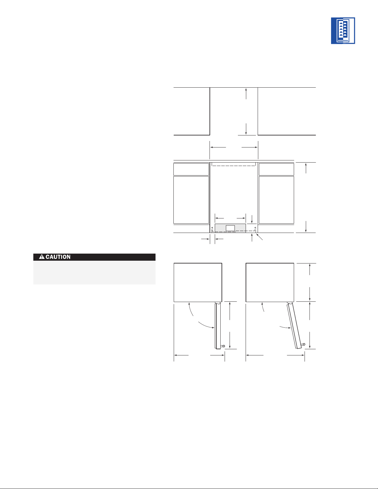
MODELS 424 AND 424FS
SITE PREPARATION
he Sub-Zero Model 424FS wine storage unit
T
is designed to be attractive in a stand alone
setting. It can also be slid into surrounding
abinetry with clearance dimensions slightly
c
different than the standard built-in Model 424.
Make sure that the finished rough opening
where the Wine Storage unit is to be installed
is properly prepared. Refer to the Installation
Specifications illustration for rough opening
dimensions, door swing clearance and electrical placement for Models 424 and 424FS.
IMPORTANT NOTE:
To operate properly, the
door must open a minimum of 90 degrees.
Use a minimum 3" (76) filler in corner installations to assure a 90-degree door opening.
Allow enough clearance in front of the unit for
full door swing.
IMPORTANT NOTE:
the unit is level with the surrounding finished
floor.
Make sure the floor under
MODELS
424 | 424FS
INSTALLATION SPECIFICATIONS
Do not load wine into the Wine Storage
unit until the installation is complete.
Dimensions in parentheses are in
millimeters unless otherwise specified.
NOTE: Door swing clearances are based on stainless
steel door and handle dimensions.
3
Page 4

MODELS 424 AND 424FS INSTALLATION
MODELS
424 | 424FS
ELECTRICAL REQUIREMENTS
A 115 V AC, 60 Hz, 15 amp circuit breaker and
electrical supply are required. A separate
ircuit, servicing only this appliance, is
c
required.
The power supply cord has a 3-prong grounding plug, which must be plugged into a mating
-prong grounding-type wall receptacle. Follow
3
the National Electrical Code and local codes
and ordinances when installing the receptacle.
For location of the electrical supply, refer to the
Installation Specifications illustration on page 3.
IMPORTANT NOTE:
For Models 424 and
424FS, the electrical outlet must be placed so
the grounding prong is to the right of the
thinner blades. The outlet must be flush with
the back wall.
IMPORTANT NOTE:
A ground fault circuit
interrupter (GFCI) is not recommended and
may cause interruption of operation.
Do not use an extension cord or twoprong adapter. Electrical ground is
required on this appliance.
UNPACKING AND MOVING
Uncrate the unit, remove its wood base and
discard the shipping bolts that hold the wood
ase to the bottom of the unit. Remove all
b
packing materials and tape.
IMPORTANT NOTE:
Do not discard the
kickplate, anti-tip bracket and hardware. These
tems will be needed for the installation.
i
All roller-assembly wine shelves should be
removed to reduce weight and prevent them
from rolling. To remove, pull the shelf out to
its full extension, gently and evenly lift up on
both sides of the front of the shelf and remove.
Reverse the procedure to reinstall the shelf.
Use an appliance dolly to move the Wine
Storage unit. Position the dolly at the back of
the unit to prevent damage to finished
surfaces.
Before moving the W
to position, protect any finished flooring
with appropriate materials and secure the
door closed.
ine Storage unit in
HOME ALARM SYSTEM
If a home alarm system is to be used, refer to
Home Alarm Connections on page 8. In addition
to operating power, the installer may also be
required to supply a home automation system
lead to the unit. This is for a low-voltage, lowcurrent signal similar to door and window
sensor signals. Common, normally open and
normally closed contact configurations ar
e
provided.
Three 1/4" (6) female spade connectors are
located in the compr
essor compar
tment and
are accessible behind the kickplate on Models
424 and 424FS. A minimum of 36" (914) of lead
wire should be pr
ovided for each contact,
exiting the back wall near the electrical outlet.
Dimensions in parentheses are in
millimeters unless otherwise specified.4
Page 5
MODELS 424 AND 424FS INSTALLATION
1
/4" (6)
Anti-Tip
Bracket
Countertop
Bracket
Anti-Tip Bracket
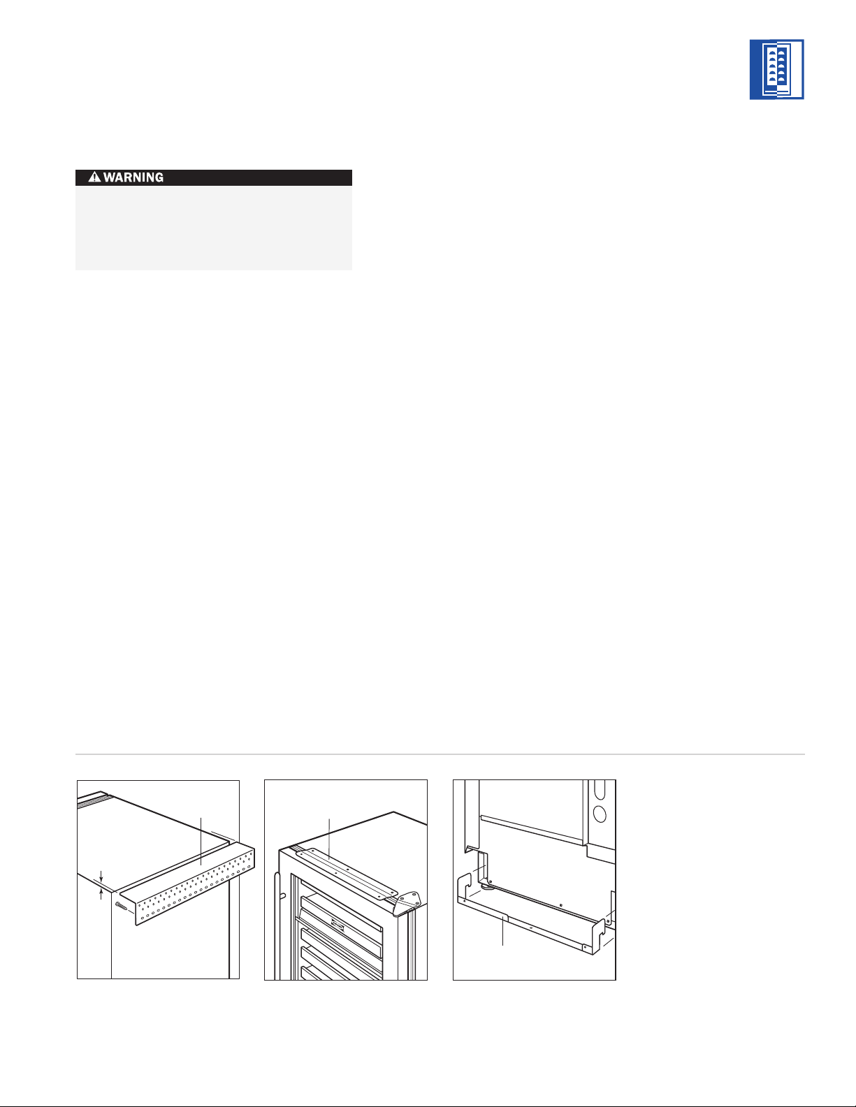
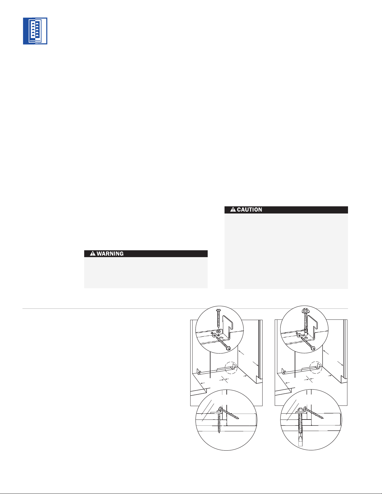
ANTI-TIP BRACKET
To prevent the unit from tipping forward
and provide a stable installation, the unit
must be secured in place with the anti-tip
bracket.
INSTALLATION
An anti-tip bracket and hardware is provided
with the Wine Storage unit. The anti-tip
bracket must be installed on a solid base to
prevent tipover in case several loaded wine
shelves are extended at the same time.
MODEL 424
The anti-tip bracket should be attached to the
wall behind the unit with the bracket flange
located immediately above the top of the unit.
Refer to illustration 1 below.
A smaller metal ‘countertop’ bracket is also
provided with the Model 424, for installations
that need to be modified to provide a secure
surface for attaching the bracket. This bracket
will secure the front of the unit to the underside of the countertop, above the unit. Refer to
illustration 2.
MODEL 424FS
f you are installing the Model 424FS in a
I
space deeper than 24
bracket must be installed no more than 24
625) deep, so it engages the unit properly. It is
(
5
/8" (625), the anti-tip
5
/8"
important that this measurement be made
from the front surface of the door, to the back
of the anti-tip bracket. Refer to illustration 3
below.
MODELS
424 | 424FS
Illus. 1
Illus. 2
Illus. 3
5
Page 6
MODELS 424 AND 424FS INSTALLATION
123/16"
(310)
123/16"
(310)
24"
(610)
C
L
WOOD FLOOR
Finished Flooring
Underlayment
Sub Flooring
Wall Plate
24"
(610)
C
L
CONCRETE
FLOOR
Finished Flooring
Underlayment
Sub Flooring
Wall Plate
11/2"
min
(38)
123/16"
(310)
123/16"
(310)
MODELS
424 | 424FS
ANTI-TIP BRACKET
INSTALLATION
WOOD FLOOR APPLICATIONS
se the four #12 x 2
U
1
four
/4" flat washers provided. Drill pilot holes
3
/16" (5) diameter maximum, and be sure that
he screws penetrate through the flooring
t
1
wood screws and the
/2"
material and into the wall plate a minimum of
3
/4" (19). Be sure that the screws hold tight.
Refer to illustration 4 below.
CONCRETE FLOOR APPLICATIONS
Use the two 3/8" x 33/4" concrete wedge
1
anchors, two #12 x 2
1
/4" flat washers provided. Be sure that the
/2" wood screws and two
anchors and screws hold tight. Refer to
illustration 5 below.
IMPORTANT NOTE:
In some installations the
subflooring or finished floor may require
angling the wood screws used to fasten the
anti-tip bracket to the back wall. Refer to
illustrations 4 and 5.
Make sure that there are no electrical
wires in the area which the scr
ews could
penetrate.
Installation for Concrete Wedge Anchors:
1)
Drill a 3/8" (10) diameter hole any depth
exceeding the minimum embedment. Clean
he hole or continue drilling additional
t
depth to accommodate drill fines. Use a
carbide drill bit manufactured within ANSI
94.12-77.
B
2)
Assemble the washer and nut flush with the
end of anchor to protect threads. Drive the
anchor through the material to be fastened
until the washer is flush with the surface
material.
3)
Expand the anchor by tightening the nut
3–5 turns past hand-tight position or to 25
foot-pounds of torque.
Always wear safety glasses and use other
necessary protective devices or apparel
when installing or working with anchors.
Anchors are not recommended for use in
lightweight masonry material such as
block or brick, or for use in new concrete
which has not had sufficient time to cure.
The use of core drills is not recommended
to drill holes for the anchors.
6
Illus. 4
Illus. 5
Page 7

MODELS 424 AND 424FS INSTALLATION
LOCK INSTALLATION
IMPORTANT NOTE:
ccessory lock kit to your Wine Storage unit, it
a
If you are adding an
should be installed before you position the
unit. Installation instructions are included with
the lock kit.
or Model 424, the lock is attached to the
F
bottom of the metal door frame. The decorative door panel is not involved in the installation or operation of the lock. The catch portion
of the lock is attached to the bottom of the
appliance cabinet in pre-punched holes. When
installing the lock kit, it may be helpful to tip
the unit on its back for easier access.
POSITION THE UNIT
IMPORTANT NOTE:
If for any reason the Wine
Storage unit has been laid on its back or side,
you must allow the unit to stand upright for a
minimum of 24 hours before connecting
power.
Plug the power supply cord into the 15 amp
grounded electrical outlet. With power applied
to the appliance, check for lighting and cooling
before going any further. Once you are satisfied that the unit is operating properly, shut off
power to the electrical outlet at the circuit
breaker and proceed.
Shut of
f the power to the electrical outlet.
If a home alarm system is to be used with the
ine Storage unit, the lead wires should be
W
threaded into the compressor compartment
before you position the unit. See Home Alarm
Connections on page 8, for the location of
these lead wires. After the unit is in position,
the alarm wiring can be completed from the
front.
Pre-level the Wine Storage unit before sliding
it into position. Leveling cannot be completed
with the unit pushed back in the installation
opening.
For Model 424FS, adust the leveling legs so
the top of the unit is no more than 34
5
/8" (879)
above the floor. This is to allow the unit to
engage the anti-tip bracket properly. Center the
Model 424FS in front of the anti-tip bracket.
Slide the unit into position, making sure the
anti-tip bracket is engaged properly.
IMPORTANT NOTE:
When the Wine Storage
unit is installed, the anti-tip bracket will be
positioned just below the engaging bracket on
the unit. It is not necessary to raise the unit up
so that it locks into the anti-tip bracket, but the
unit must be in alignment with the anti-tip
bracket.
The Wine Storage unit provides the best
access to its contents when the front surface of
the door panel extends out from surrounding
cabinets appr
424FS, if ther
oximately
e ar
1
e no surrounding cabinet
/4" (6).
For Model
surfaces to gauge depth, slide the unit back
until it engages the anti-tip bracket.
MODELS
424 | 424FS
Dimensions in parentheses are in
millimeters unless otherwise specified.
NOTE:
IMPORT
ANT
The floor under the Wine
Storage unit must be at the same level as the
ounding finished floor to allow for removal
r
sur
of the unit for servicing.
7
Page 8
MODELS 424 AND 424FS INSTALLATION
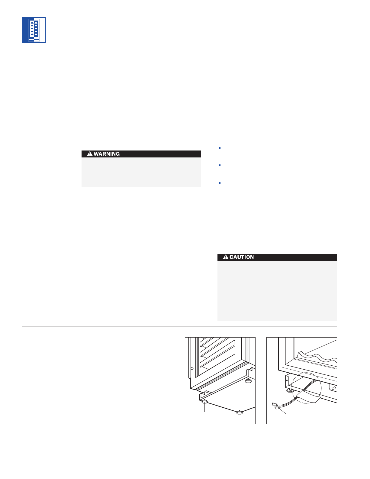
Leveling Legs
Home Alarm
Connections
MODELS
424 | 424FS
LEVEL THE UNIT
Using an adjustable wrench or pliers, turn
ach of the four leveling legs clockwise to raise
e
the unit and counterclockwise to lower the
unit. For the location of the leveling legs, see
illustration 6 below.
For Model 424, the countertop bracket should
e used to make a solid installation. Refer to
b
illustration 2 on page 5. If this is not possible,
wedge shims along the sides and top.
To reduce the possibility of the unit
tipping forward, the front leveling legs
must be in contact with the floor.
HOME ALARM CONNECTIONS
Before the kickplate is installed, all necessary
wiring connections in the compressor compart-
ent should be completed.
m
f a home alarm system is to be installed on
I
the Wine Storage unit, the connections should
be made using the logic supplied with the
larm specifications. See illustration 7 below
a
for the appliance lead locations, and refer to
the following for color codes:
Normally open contacts – white with red
stripe wire
Normally closed contacts – white with blue
stripe wire
Common – gray with white stripe wire
Use the
1
/4" (6) spade terminals or wire nuts
provided to make the proper wiring connections.
IMPORTANT NOTE:
If you are not responsible
for alarm system connection, this information
should be supplied to the home security
system contractor.
Illus. 6
The alarm circuit in the unit is intended as
a low-voltage, low-current device only. It
should not be used to switch line power.
Any unused terminals should be
completely insulated and all wires should
be secur
moving components.
ed away from conductive or
Illus. 7
8
Page 9
MODELS 424 AND 424FS INSTALLATION
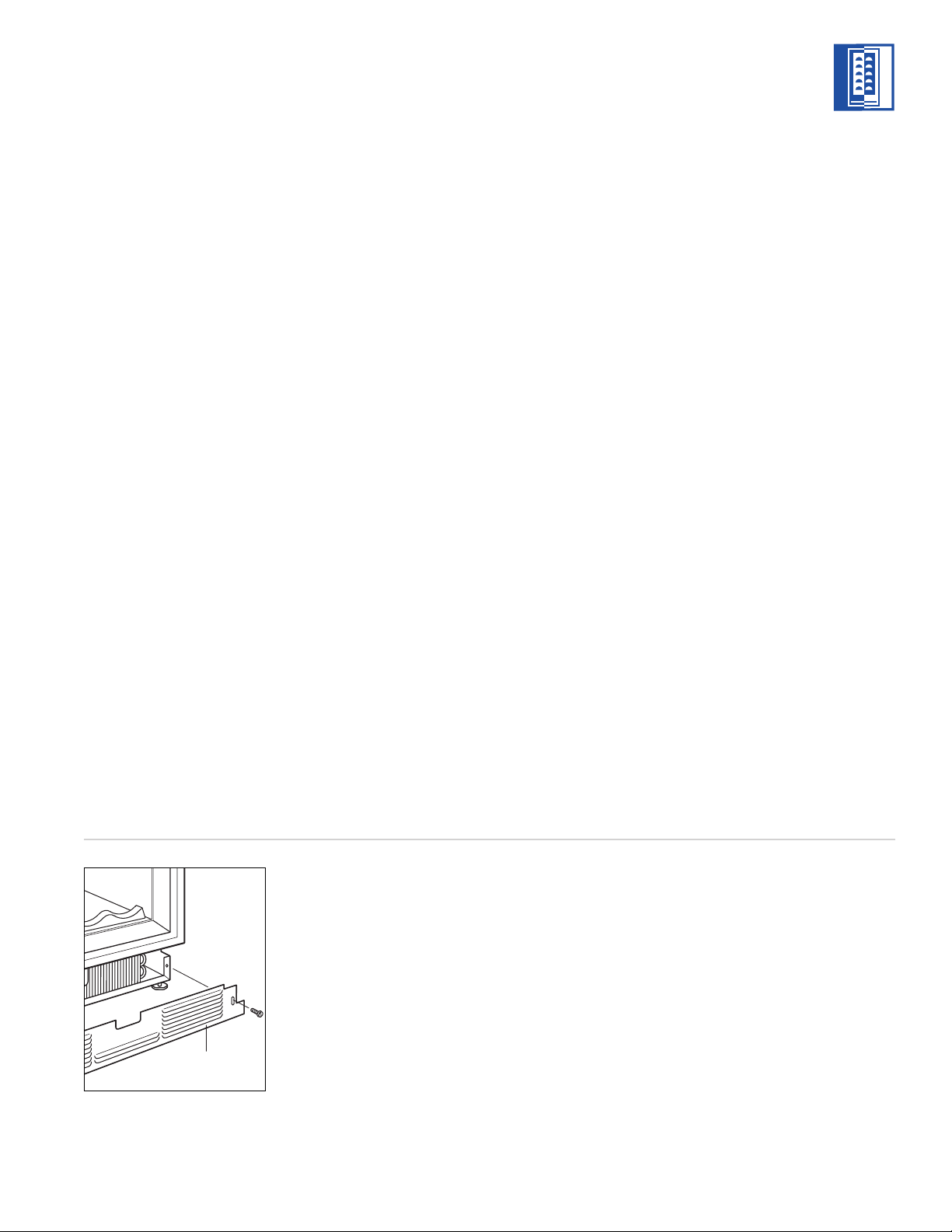
Kickplate
KICKPLATE INSTALLATION
Once the unit is leveled and wiring connections
ade, the kickplate can be installed. Use the
m
two #10 x
1
/2" stainless steel screws that are
provided with the kickplate. Refer to illustration
8 below.
IMPORTANT NOTE:
emoved for servicing. The floor cannot inter-
r
The kickplate must be
fere with removal. The louvered section of the
kickplate must not be covered so as to prevent
air circulation.
Turn power back on to the electrical outlet.
DOOR PANELS – MODEL 424
Model 424 is offered in two design applications; stainless steel (/S) and overlay (/O). Each
f these designs are available as a glass door
o
(G) model.
The stainless steel Model 424 is available in
the classic finish only and is shipped from the
actory with the decorative stainless steel door
f
panel and matching handle in place.
The overlay Model 424/O is designed to accept
a decorative door panel to match surrounding
cabinetry. The door panel and the handle will
be provided by the customer.
The solid door Model 424S—with no glass
window—requires a different door panel than
the glass door design.
Before beginning installation, check for the
correct components for the fit and finish
desired. All overlay doors require a decorative
panel 23
minimum
3
/4" (603) by 301/16" (764) and a
5
/8" (16) thick.
MODELS
424 | 424FS
PANEL
DESIGN
Additional panel
design information
can be found in
the Sub-Zero
Design Guide.
Check our website
at subzero.com.
IMPORTANT NOTE:
For installations at or
above 5,000' (1524 m) in altitude, a special
high altitude glass door unit (HA) must be
ordered.
If you have questions, contact your Sub-Zero
dealer or cabinet supplier. Additional panel
information can be found in the Sub-Zero
Design Guide.
Illus. 8
Dimensions in parentheses are in
millimeters unless otherwise specified.
9
Page 10

MODELS 424 AND 424FS INSTALLATION
MODELS
424 | 424FS
PANEL
DESIGN
Additional panel
design information
can be found in
the Sub-Zero
Design Guide.
Check our website
at subzero.com.
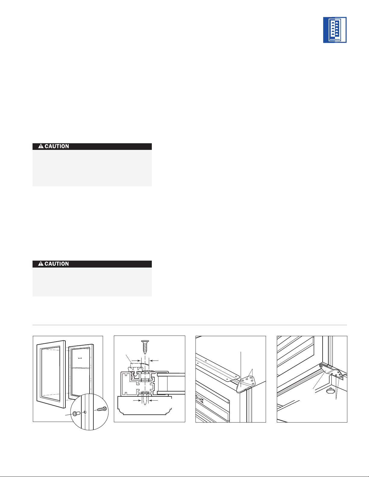
OVERLAY DOOR PANELS
OVERLAY GLASS DOOR – MODEL 424
nspect the door panel for the minimum
I
5
/8"
(16) thickness, the finished inside edge and the
10 lbs (5 kg) weight limit. See the Wine
torage section of the Sub-Zero Design Guide
S
for additional panel information.
Decide if the handle will be attached through
the glass door frame or just through the decorative door panel. If it is just through the door
panel, the handle must be attached first.
Decorative panels are attached to the Model
424 door using #8 x
5
/8" square drive screws
passing through the door frame from the rear,
behind the gasket into the panel. The door
panel is marked for screw locations by the use
of ‘tenon centers’, which are temporarily
1
inserted into the
/4" (6) diameter holes in the
front of the glass door frame. Refer to illustration 9 on page 11.
With the Wine Storage unit secured in position
and the door closed, the panel is held in the
desired position on the door and rapped by
hand from the front, putting center marks on
the rear surface of the panel. If the door panel
is made of such a material that pre-drilling is
needed, all of the mounting holes should be
marked. If not, only enough holes to hold the
panel in place temporarily, are necessary.
The door panel is then lowered from the door
frame, tenon centers removed, the door
opened and the screws driven into the panel
through the black tape on the door frame,
using the center marks to locate the screws.
The screw holes inside the door ar
e hidden
under a cover flap on the door gasket. It is
necessary to lift the flap to insert the screws.
Use as many scr
ews as necessar
y to hold the
door panel in place properly.
IMPORTANT NOTE:
After the first three or
four mounting screws are in place, but not
ompletely tightened, close the door and check
c
your panel fit. This is the time to make small
adjustments. Once you are satisfied with the
ppearance, open the door and apply the
a
remainder of the screws. Check all screws for
tightness.
The metal frame on the glass door has
numerous mounting holes on each side of the
door. This is to accommodate the Sub-Zero
accessory handles and provide for easy attachment of the handle through the door frame.
If you choose not to use the pre-drilled handle
mounting holes, it will be necessary to fasten
the handle from the rear of the door panel
only, or drill one or more additional holes
through the metal frame of the glass door.
Illustration 10 on page 11 shows how this hole
passes through the door frame. The hole
center is on the small locator groove in the
front of the frame. A
1
/4" (6) diameter hole is
made in the front wall of the extrusion and a
13
/32" (11) diameter hole through the rest of the
frame.
The wine storage unit door is made with
a sealed double wall tempered glass core.
The drill must not contact this core when
drilling. Be sur
the small groove in the front of the door
frame and the drill passes squarely
through the frame. If you are inexperienced with drilling, fasten the handle from
ear of the door panel only.
the r
e the hole is centered on
Dimensions in parentheses are in
millimeters unless otherwise specified.10
Page 11
Door
Frame
Overlay
Panel
Tenon Center
1
/4" (6)
Diameter
13
/32" (11)
Diameter
Glass
Gasket
MODELS 424 AND 424FS INSTALLATION
Top Door Hinge
Shipping
Screws
Shipping
Screws
Bottom
Door Hinge
IMPORTANT NOTE:
Install screws in all the
mounting holes in the door frame. The nature
f the door panel with a narrow outer rim and
o
no connecting center member requires the
support provided by the glass door.
After the door panel installation is complete,
pply the cover patches or plugs provided over
a
the holes on the inside surface of the door.
The cover patches or plugs are part of the
insulation system on the door of the Wine
Storage unit. Be sure to cover all the
holes in the door that were used.
OVERLAY SOLID DOOR – MODEL 424
IMPORTANT NOTE:
the Model 424 must be a minimum of
The solid door panel for
5
/8" (16)
thick and cannot exceed 20 lbs (9 kg).
Installation of the solid door panel is the same
as the door panel for a glass door model.
A solid panel must not be installed on a
glass door unit, as this may cause
moistur
e to form behind the panel.
HINGE ADJUSTMENT
IMPORTANT NOTE:
The Wine Storage unit
must be installed and leveled before door
inge adjustments can be made.
h
he top and bottom cabinet hinges on Models
T
424 and 424FS are held in place with three
permanent adjustment screws and two
hipping screws. Refer to illustrations 11 and
s
12 below. The shipping screws must be
removed and discarded to adjust the door
alignment and fit. If no adjustments are necessary, it is recommended that all five screws
remain in place.
On the Model 424FS, only the bottom door
hinge can be adjusted. Remove and discard
the two shipping screws and loosen the three
hinge screws to adjust the door. Refer to
illustration 12.
COMPLETING THE INSTALLATION
IMPORTANT NOTE:
When you have
completed the installation of the Model 424
or 424FS Wine Storage unit, refer to pages
34–35 for the Installation Checklist and Service
Information.
MODELS
424 | 424FS
Illus. 9
Illus. 10
Illus. 11
Illus. 12
11
Page 12

MODELS 427 AND 427R INSTALLATION
27"
(
686)
ROUGH OPENING WIDTH
25"
(635)
R
OUGH
O
PENING
DEPTH
237/8"
(606)
90˚
105˚
MAXIMUM
DOOR SWING
35" (889)
DOOR CLEARANCE
28" (711)
DOOR CLEARANCE
251/2"
(648)
251/2"
(648)
151/2"
(394)
LOCATE ELECTRICAL
WITHIN SHADED AREA
E
4
1
/2"
(
114
)
21/2"
(64)
ANTI-TIP BRACKET
FRONT VIEW
T
OP VIEW
80" (
2032)
R
OUGH OPENING
HEIGHT
T
O FINISHED
FLOORING
791/2" (2019)
MIN HEIGHT
R
EQUIRED
MODELS
427 | 427R
MODELS 427 AND 427R
INSTALLATION SPECIFICATIONS
SITE PREPARATION
Make sure that the finished rough opening
where the Wine Storage unit is to be installed
s properly prepared. Refer to the Installation
i
Specifications illustration for rough opening
dimensions, door swing clearance and electri-
al placement for Models 427 and 427R.
c
IMPORTANT NOTE:
To operate properly, the
door must open a minimum of 90 degrees.
Use a minimum 2" (51) filler in corner installations to assure a 90-degree door opening.
Allow enough clearance in front of the unit for
full door swing.
IMPORTANT NOTE:
Make sure the floor under
the unit is level with the surrounding finished
floor.
Do not load wine into the W
ine Storage
unit until the installation is complete.
12
NOTE: Door swing clearances are based on stainless
steel door and handle dimensions.
Page 13

MODELS 427 AND 427R INSTALLATION
ELECTRICAL REQUIREMENTS
A 115 V AC, 60 Hz, 15 amp circuit breaker and
lectrical supply are required. A separate
e
circuit, servicing only this appliance, is
required.
The power supply cord has a 3-prong grounding plug, which must be plugged into a mating
-prong grounding-type wall receptacle. Follow
3
the National Electrical Code and local codes
and ordinances when installing the receptacle.
For location of the electrical supply, refer to
the Installation Specifications illustration on
page 12.
IMPORTANT NOTE:
For Models 427 and 427R,
the electrical outlet must be placed so the
grounding prong is to the right of the thinner
blades. The outlet must be flush with the back
wall.
IMPORTANT NOTE:
A ground fault circuit
interrupter (GFCI) is not recommended and
may cause interruption of operation.
Do not use an extension cord or twoprong adapter
required on this appliance.
. Electrical ground is
UNPACKING AND MOVING
Uncrate the unit, remove its wood base and
discard the shipping bolts that hold the wood
ase to the bottom of the unit. Remove all
b
packing materials and tape.
IMPORTANT NOTE:
Do not discard the
kickplate/grille, anti-tip bracket and hardware.
hese items will be needed for the installation.
T
All roller-assembly wine shelves should be
removed to reduce weight and prevent them
from rolling. To remove, pull the shelf out to
its full extension, gently and evenly lift up on
both sides of the front of the shelf and remove.
Reverse the procedure to reinstall the shelf.
Retract the front leveling legs to allow you to
move the unit more easily during installation.
You will extend the leveling legs when the unit
is in its final position to reduce the possibility
of the unit tipping forward.
Use an appliance dolly to move the Wine
Storage unit. Position the dolly at the side of
the unit to prevent damage to finished
surfaces.
Before moving the Wine Storage unit into
position, protect any finished flooring
with appropriate materials.
MODELS
427 | 427R
HOME ALARM SYSTEM
If a home alarm system is to be used, refer to
Other Wiring Connections on page 18. In
addition to operating power, the installer may
also be required to supply a home automation
system lead to the unit. This is for a lowvoltage, low-current signal similar to door and
window sensor signals. Common, normally
open and nor
mally closed contact configura-
tions are provided.
1
Three
located in the compr
/4" (6) female spade connectors are
essor compartment and
are accessible behind the kickplate/grille on
Models 427 and 427R. A minimum of 36" (914)
of lead wir
e should be pr
ovided for each
contact, exiting the back wall near the
electrical outlet.
Dimensions in parentheses are in
millimeters unless otherwise specified.
13
Page 14

MODELS 427 AND 427R INSTALLATION
WOOD FLOOR
Finished Flooring
Underlayment
Subflooring
Wall Plate
Finished Flooring
Underlayment
Subflooring
Wall Plate
CONCRETE
FLOOR
1
1
/2"
min
(38)
MODELS
427 | 427R
ANTI-TIP BRACKET
INSTALLATION
To prevent the unit from tipping forward
and provide a stable installation, install
the anti-tip bracket and extend the front
leveling legs to the floor.
An anti-tip bracket and hardware is provided
with the Wine Storage unit. The anti-tip
bracket must be installed on a solid base to
prevent tipover in case several loaded wine
shelves are extended at the same time.
If you ar
e installing the Model 427 or 427R in a
space deeper than 24" (610), the anti-tip
bracket must be installed no more than 24"
(610) deep, so it engages the unit properly. It is
important that this measurement be made
from the front of the unit without panels, to
the back of the anti-tip bracket.
WOOD FLOOR APPLICATIONS
Use the six #12 x 21/2" wood screws and the
1
six
/4" flat washers provided. Drill pilot holes
3
(5) diameter maximum, and be sure that
/16"
the screws penetrate through the flooring
material and into the wall plate a minimum of
3
(19). Be sure that the screws hold tight.
/4"
Refer to illustration 1 below.
CONCRETE FLOOR APPLICATIONS
Use the two 3/8" x 33/4" concrete wedge
1
anchors, two #12 x 2
1
/4" flat washers provided. Be sure that the
/2" wood screws and two
anchors and screws hold tight. Refer to illustration 2 below.
IMPORTANT NOTE:
In some installations the
subflooring or finished floor may require
angling the wood screws used to fasten the
anti-tip bracket to the back wall. Refer to illustrations 1 and 2 below.
SPECIFICATIONS
Dimension A 131/2" (343)
Illus. 1
Make sure that there are no electrical
wires in the area which the screws could
penetrate.
Illus. 2
14
Page 15

MODELS 427 AND 427R INSTALLATION
Installation for Concrete Wedge Anchors:
1)
Drill a 3/8" (10) diameter hole any depth
exceeding the minimum embedment. Clean
he hole or continue drilling additional
t
depth to accommodate drill fines. Use a
carbide drill bit manufactured within ANSI
94.12-77.
B
2)
Assemble the washer and nut flush with the
end of anchor to protect threads. Drive the
anchor through the material to be fastened
until the washer is flush with the surface
material.
3)
Expand the anchor by tightening the nut
3–5 turns past hand-tight position or to 25
foot-pounds of torque.
Always wear safety glasses and use other
necessary protective devices or apparel
when installing or working with anchors.
Anchors are not recommended for use in
lightweight masonry material such as
block or brick, or for use in new concrete
which has not had sufficient time to cure.
The use of core drills is not recommended
to drill holes for the anchors.
POSITION THE UNIT
Before moving the Wine Storage unit into
position, secure the door closed. Remove
the drawers of the Model 427R.
MPORTANT NOTE: For Model 427R, the top
I
drawer has a control cable that needs to be
disconnected before removing this drawer.
Refer to illustration 3 below for placement and
how to disconnect this fitting.
For Model 427R, the drawers should be placed
aside until you are ready for installation of the
door and drawer panels.
IMPORTANT NOTE:
When two Model 427,
427R or Integrated units are installed closer
than 2" (51) to one another, it is necessary
to use the Sub-Zero dual installation heater
kit. Contact your Sub-Zero dealer or call
800-222-7820 for the proper components and
additional instructions. The heater plate from
this dual installation heater kit must be
attached to the left side exterior of the right
hand unit before the unit is slid into position.
MODELS
427 | 427R
OPTIONAL
COMPONENTS
Optional installation components
are available
through your
Sub-Zero dealer,
or call Sub-Zero at
800-222-7820.
You can also visit
our website at
subzero.com.
Illus. 3
Dimensions in parentheses are in
millimeters unless otherwise specified.
15
Page 16

MODELS 427 AND 427R INSTALLATION
MODELS
427 | 427R
POSITION THE UNIT
IMPORTANT NOTE:
ccessory lock kit to your Model 427 or 427R,
a
If you are adding an
the catch should be installed at the top of
appliance cabinet before you position the unit.
See Lock Installation on page 23. Installation
instructions are included with the lock kit.
Remove the decorative top and side moldings
and the kickplate/grille of the Wine Storage
unit.
IMPORTANT NOTE:
If for any reason the Wine
Storage unit has been laid on its back or side,
you must allow the unit to stand upright for a
minimum of 24 hours before connecting
power.
Plug the power supply cord into the 15 amp
grounded electrical outlet. With power applied
to the appliance, check for lighting and cooling
before going any further. Once you are satisfied that the unit is operating properly, shut off
power to the electrical outlet at the circuit
breaker and proceed.
If a home alarm system is to be used with the
ine Storage unit, the lead wires should be
W
threaded into the compressor compartment
before you position the unit. See Other Wiring
Connections on page 18 for the location of
these lead wires. After the unit is in position,
the alarm wiring can be completed from the
front.
Pre-level the Wine Storage unit before rolling
into position. This is to allow the unit to
engage the anti-tip bracket properly.
Roll the unit into position, making sure the
anti-tip bracket is engaged properly. Screw the
front leveling legs out approximately
3
/16" (5) to
make any future adjustments easier.
IMPORTANT NOTE:
When the Wine Storage
unit is installed, the anti-tip bracket will be
positioned just below the engaging bracket on
the unit. It is not necessary to raise the unit up
so that it locks into the anti-tip bracket, but the
unit must be in alignment with the anti-tip
bracket.
Shut off the power to the electrical outlet.
IMPORTANT NOTE:
The floor under the Wine
Storage unit must be at the same level as the
surrounding finished floor to allow for removal
of the unit for servicing.
16
Page 17

MODELS 427 AND 427R INSTALLATION
Top Molding
LEVEL THE UNIT
Level the unit by turning the front leveling legs
lockwise to raise the unit, or counterclockwise
c
to lower it. To assist you in adjusting the front
leveling legs up or down, use a standard
screwdriver blade and place it in the front
leveling leg as shown in illustration 4 below.
he rear leveling legs are adjusted from the
T
front of the base by turning the Phillips head
screw. Refer to illustration 5.
IMPORTANT NOTE:
only move
1
/16" (2) for every 18 revolutions on
The rear leveling legs will
the Phillips head screw. Do not over torque.
Use the lowest torque setting on any power
screwdriver. Do not turn the rear leveling legs
by hand. Damage will occur if you turn these
legs.
To reduce the possibility of the unit
tipping forward, the front leveling legs
must be in contact with the floor.
MOLDING INSTALLATION
The decorative white molding strips for the
ide and top of Models 427 and 427R can be
s
snapped into place. The top molding piece
must be installed before the side molding can
be attached. For installation of the top
molding, refer to illustration 6 below. Refer to
illustration 7 for side molding installation. For
installations where units are side by side, see
Finished Wood Side Panels on page 23.
MODELS
427 | 427R
Illus. 4
Dimensions in parentheses are in
millimeters unless otherwise specified.
Illus. 5
Illus. 6
Illus. 7
17
Page 18

MODELS 427 AND 427R INSTALLATION
Home Alarm
Connections
MODELS
427 | 427R
OPTIONAL
COMPONENTS
Optional installation components
are available
through your
Sub-Zero dealer,
or call Sub-Zero at
800-222-7820.
You can also visit
our website at
subzero.com.
OTHER WIRING CONNECTIONS
Before the kickplate/grille is installed, all
ecessary wiring connections in the compres-
n
sor compartment should be completed.
f the dual installation heater kit (#7007529) is
I
used with Model 427 or 427R, the power
supply leads should be connected according to
nstructions included with the kit.
i
If a home alarm system is to be installed on
the Wine Storage unit, the connections should
be made using the logic supplied with the
alarm specifications. See illustration 8 below
for the appliance lead locations, and refer to
the following for color codes:
Normally open contacts – white with red
stripe wire
Normally closed contacts – white with blue
stripe wire
Common – gray with white stripe wire
Use the
1
/4" (6) spade terminals or wire nuts
provided to make the proper wiring connections.
IMPORTANT NOTE:
or alarm system connection, this information
f
If you are not responsible
should be supplied to the home security
system contractor.
The alarm circuit in the unit is intended as
a
low-voltage, low-current device only. It
should not be used to switch line power.
Any unused terminals should be
completely insulated and all wires should
be secured away from conductive or
moving components.
18
Illus. 8
Page 19

MODELS 427 AND 427R INSTALLATION
KICKPLATE/ GRILLE INSTALLATION
Once the unit is leveled and wiring connec-
ions made, the kickplate/grille can be
t
installed.
MPORTANT NOTE: The kickplate/grille must
I
be removed for servicing. The floor cannot
interfere with removal. The louvered section of
he kickplate/grille must not be covered so as
t
to prevent air circulation.
For Models 427 and 427R, there is some
adjustment to the mounting assembly so that
the kickplate/grille can fit flush with the
surrounding area. Refer to illustration 9 below.
IMPORTANT NOTE:
The unit must be allowed
to have ventilation through the fins of the kickplate/grille. You may cover the solid area, but
do not block the fins. For Model 427R, the
lower drawer panel may hang in front of the
fins, but your baseboard molding must not
cover them.
Turn power back on to the electrical outlet.
DOOR PANELS
Models 427 and 427R are available as a glass
door (G) or solid door (S) model. Each of these
Wine Storage units are set up at the job site as
either the stainless steel or integrated design.
Stainless steel panels in three finishes in most
cases; classic (/S), platinum (/P) and carbon
/B)—available as sales accessories—may be
(
configured several ways and are shipped
separately. Stainless steel panels are shipped
ith matching handles in place.
w
he integrated design uses custom wood or
T
other decorative panels and handles provided
by the customer.
Model 427R requires solid panels on the
drawers that may match the door panel, or be
complementary. The Model 427R stainless
steel drawer panel set and stainless steel door
panel are ordered and shipped as two items.
The solid door Model 427S or 427RS—with no
glass window—requires a different door panel
than the glass door design.
Before beginning installation, check for the
correct components for the fit and finish
desired. The door and drawers (Model 427R)
require a decorative panel that is a minimum
5
/8" (16) thick.
IMPORTANT NOTE:
For installations at or
above 5,000' (1524 m) in altitude, a special
high altitude glass door unit (HA) must be
ordered.
If you have questions, contact your Sub-Zero
dealer or cabinet supplier. Additional panel
information can be found in the Sub-Zero
Design Guide.
MODELS
427 | 427R
PANEL
DESIGN
Additional panel
design information
can be found in
the Sub-Zero
Design Guide.
Check our website
at subzero.com.
Illus. 9
Dimensions in parentheses are in
millimeters unless otherwise specified.
19
Page 20

Door
Frame
Stainless
Steel
Panel
Back of
Stainless Steel
Panel
Door
Frame
Integrated
Panel
Tenon Center
1
/4" (6)
Diameter
13
/32" (11)
Diameter
Glass
Gasket
MODELS 427 AND 427R INSTALLATION
MODELS
427 | 427R
PANEL
DESIGN
Additional panel
design information
can be found in
the Sub-Zero
Design Guide.
Check our website
at subzero.com.
STAINLESS STEEL DOOR PANEL
Before installing the stainless steel door panel,
heck the panel carefully. Options are available
c
for kickplate/grille height, overall height, door
swing and door lock.
The stainless steel panel is mounted to the
door by passing the #8–32 x
rovided, through holes in the door frame
p
5
/8" screws
from the rear, and into the threaded holes in
the door panel. Refer to illustration 10 below.
The screw holes inside the door are hidden
under a cover flap on the door gasket. It is
necessary to lift the flap to insert the screws.
After the door panel installation is complete,
apply the cover patches or plugs provided over
the holes on the inside surface of the door.
For installation of stainless steel panels on
Model 427R drawers, see Model 427R Drawer
Panels on page 22.
The cover patches or plugs are part of the
insulation system on the door of the W
ine
Storage unit. Be sure to cover all the
holes in the door that were used.
OVERLAY GLASS DOOR PANEL
Inspect the door panel for the minimum 5/8"
16) thickness, the greater width requirements
(
for the stiles (to cover the door hinges), and
the finished inside edge. The door panel has a
weight limit of 20 lbs (9 kg). See the Wine
Storage section of the Sub-Zero Design Guide
for additional panel information.
Decide if the handle will be attached through
the glass door frame or just through the decorative door panel. If it is just through the door
panel, the handle must be attached first.
If a lock is to be used, the body of the lock
should be installed on the door panel after the
panel is mounted.
Decorative panels are attached to the Model
427 and 427R door using #8 x
5
/8" square drive
screws passing through the door frame from
the rear, behind the gasket into the panel. The
door panel is marked for screw locations by
the use of ‘tenon centers’, which are temporarily inserted into the
1
/4" (6) diameter holes in
the front of the glass door frame. Refer to
illustration 11 below.
20
Illus. 10
Illus. 12
Illus. 11
Page 21

MODELS 427 AND 427R INSTALLATION
MODELS
427 | 427R
With the Wine Storage unit secured in position
nd the door closed, the panel is held in the
a
desired position on the door and rapped by
hand from the front, putting center marks on
the rear surface of the panel. If the door panel
is made of such a material that pre-drilling is
needed, all of the mounting holes should be
marked. If not, only enough holes to hold the
panel in place temporarily, are necessary.
The door panel is then lowered from the door
frame, tenon centers removed, the door
opened and the screws driven into the panel
through the black tape on the door frame,
using the center marks to locate the screws.
The screw holes inside the door are hidden
under a cover flap on the door gasket. It is
necessary to lift the flap to insert the screws.
Use as many screws as necessary to hold the
door panel in place properly.
IMPORTANT NOTE:
After the first three or
four mounting screws are in place, but not
completely tightened, close the door and check
your panel fit. This is the time to make small
adjustments. Once you are satisfied with the
appearance, open the door and apply the
remainder of the screws. Check all screws for
tightness.
The metal frame on the glass door has
numerous mounting holes on each side of the
door. This is to accommodate the Sub-Zero
accessory handles and provide for easy attachment of the handle through the door frame.
If you choose not to use the pre-drilled handle
mounting holes, it will be necessar
y to fasten
the handle from the rear of the door panel
only, or drill one or more additional holes
ough the metal frame of the glass door
thr
.
Illustration 12 on page 20 shows how this hole
passes through the door frame. The hole
enter is on the small locator groove in the
c
front of the frame. A
1
/4" (6) diameter hole is
made in the front wall of the extrusion and a
13
(11) diameter hole through the rest of the
/32"
frame.
The wine storage unit door is made with
a sealed double wall tempered glass core.
The drill must not contact this core when
drilling. Be sure the hole is centered on
the small groove in the front of the door
frame and the drill passes squarely
through the frame. If you are inexperienced with drilling, fasten the handle from
ear of the door panel only.
the r
IMPORTANT NOTE:
Install screws in all the
mounting holes in the door frame. The nature
of the door panel with a narrow outer rim and
no connecting center member requires the
support provided by the glass door.
After the door panel installation is complete,
apply the cover patches or plugs provided over
the holes on the inside surface of the door.
The cover patches or plugs are part of the
insulation system on the door of the Wine
Storage unit. Be sure to cover all the
holes in the door that wer
e used.
Dimensions in parentheses are in
millimeters unless otherwise specified.
21
Page 22

MODELS 427 AND 427R INSTALLATION
Back Of
Drawer Panel
Gap On Side
Edges Will Var y
According To
Design
Top Of Template
Flush With Top Of
Drawer Panel
MODELS
427 | 427R
PANEL
DESIGN
Additional panel
design information
can be found in
the Sub-Zero
Design Guide.
Check our website
at subzero.com.
MODEL 427R DRAWER PANELS
IMPORTANT NOTE:
27R must be a minimum of
4
Drawer panels for Model
5
(16) thick and
/8"
cannot exceed 12 lbs (5 kg) for each panel.
emove the mounting hardware provided and
R
set aside. You should work on the back side of
each drawer panel and you should protect the
ronts of these panels.
f
Position the top edge of the drawer template
flush with the top edge of each drawer. For the
top drawer, there is only one place for the
lower mounting bracket to be placed. However,
depending on the depth of the lower drawer
panel, you have two options for placement of
the bracket. Refer to illustration 13 below.
Secure the template in place with tape or small
clamps and mark positions for your pilot holes.
Remove template. Drill pilot holes and place
the hardware in the proper place (dog-ear
bracket on top) and fasten securely with the
1
#8 x
/2" screws provided. See illustration 14.
To help with proper placement of drawer
panels, examine the lower panel mounting
bracket and determine which slotted holes to
use. Position screws into the lower portion of
the drawer that correspond with these slotted
holes. Leave these screws out a small distance
so they can help when you mount the drawer
panels to the drawer.
With the two brackets in place on the drawer
anel, engage the top dog-ear bracket first and
p
then the lower bracket onto the protruding
1
screws. You will have a
/4" (6) adjustment up
and down and side to side in each drawer
panel. Fasten all screws to the lower bracket to
secure the drawer panel.
IMPORTANT NOTE:
Once drawer panels have
been adjusted for proper spacing, be sure to
reconnect the control cable on the upper
drawer after you have installed the drawer.
Refer to illustration 3 on page 15.
SOLID DOOR PANELS
IMPORTANT NOTE:
The solid door panel for
Models 427 and 427R must be a minimum of
5
/8" (16) thick and cannot exceed 40 lbs (18 kg).
Installation of the solid door panel is the same
as the door panel for a glass door model.
A solid panel must not be installed on a
glass door unit, as this may cause
moisture to form behind the panel.
22
Illus. 13
Illus. 14
Page 23

MODELS 427 AND 427R INSTALLATION
FINISHED WOOD SIDE PANELS
Side panels for Models 427 and 427R are not
ttached to the unit. You must securely fasten
a
the panels to adjacent cabinets and floor.
anels should be fastened to the floor and
P
walls using ‘L’ brackets (hardware not
provided). To help you move the unit into
lace, rout out an area in the floor so the ‘L’
p
bracket will sit flush with the floor level.
Brackets and screws are provided for
mounting the unit to adjoining cabinets and
side panels. Each unit has four side-mounting
clips on each side.
IMPORTANT NOTE:
For installations where
you are not attaching to a side wall, or you are
installing two Model 427, 427R or Integrated
units together, you must remove the sidemounting clips before moving the unit into
position. After removing the clips, replace the
screws into the appliance.
A dual installation heater kit (#7007529) is
necessary for anchoring two Model 427, 427R
or Integrated units together. Contact your
Sub-Zero dealer or call 800-222-7820 for
details.
LOCK INSTALLATION
For Models 427 and 427R, the accessory lock is
ttached to the decorative door panel through
a
a field-drilled hole in the panel. The catch
should be installed on the top of appliance
cabinet before the unit was moved into
position. Installation instructions are included
with the lock kit.
IMPORTANT NOTE:
For accessory stainless
steel panels requiring a lock, panels must be
ordered with the lock mounting hole predrilled.
90-DEGREE DOOR STOP
Models 427 and 427R have a 90-degree door
stop built into the hinge system. Use the blade
edge of a standard screwdriver and rotate the
brass cam in the center portion of the hinge
until you reach the stop. You must make this
adjustment to both the bottom and top hinge.
Refer to illustration 15 below.
COMPLETING THE INSTALLATION
MODELS
427 | 427R
OPTIONAL
COMPONENTS
Optional installation components
are available
through your
Sub-Zero dealer,
or call Sub-Zero at
800-222-7820.
You can also visit
our website at
subzero.com.
Illus. 15
IMPORTANT NOTE:
When you have
completed the installation of the Model 427
or 427R Wine Storage unit, refer to pages
35 for the Installation Checklist and Ser
–
4
3
Information.
Dimensions in parentheses are in
millimeters unless otherwise specified.
vice
23
Page 24

MODEL 430 INSTALLATION INSTRUCTIONS
751/2"
(
1918)
7"
(
178)
6"
(
152)
291/2"
(749)
ROUGH OPENING WIDTH
24"
(
610)
ROUGH
O
PENING
D
EPTH
E
LOCATE ELECTRICAL
W
ITHIN SHADED AREA
ANTI-TIP BLOCK
90˚
130˚
MAXIMUM
DOOR SWING
50" (1270)
DOOR CLEARANCE
33" (838)
DOOR CLEARANCE
301/8"
(765)
301/8"
(765)
237/8"
(606)
BEHIND
FRAME
FRONT VIEW
T
OP VIEW
833/4" (
2127)
ROUGH OPENING
HEIGHT
T
O FINISHED
FLOORING WITH
S
TANDARD
1
1" (279) GRILLE
83" (2108)
M
IN HEIGHT
REQUIRED
(LEVELERS IN)
MODEL 430
MODEL 430 INSTALLATION
INSTALLATION SPECIFICATIONS
SITE PREPARATION
ake sure that the finished rough opening
M
where the Wine Storage unit is to be installed
is properly prepared. Refer to the Installation
pecifications illustration for rough opening
S
dimensions, door swing clearance and electrical placement for Model 430.
If you are installing two Model 430 units side
by side, or a Model 430 and a Built-In model, a
separating filler strip is recommended. Add the
filler strip width to the finished rough opening
dimension. Complete the installation with the
Anchoring Kit (part #4200900), see page 33.
IMPORTANT NOTE:
To operate properly,
the door must open a minimum of 90 degrees.
Use a minimum 3" (76) filler strip in corner
installations to assure a 90-degree door
opening. Allow enough clearance in front of
the unit for full door swing.
IMPORTANT NOTE:
Make sure the floor under
the unit is level with the surrounding finished
floor.
Do not load wine into the Wine Storage
unit until the installation is complete.
24
NOTE: Door swing clearances are based on stainless
steel door and handle dimensions.
Page 25

MODEL 430 INSTALLATION INSTRUCTIONS
ELECTRICAL REQUIREMENTS
A 115 V AC, 60 Hz, 15 amp circuit breaker and
lectrical supply are required. A separate
e
circuit, servicing only this appliance, is
required.
The power supply cord has a 3-prong grounding plug, which must be plugged into a mating
-prong grounding-type wall receptacle. Follow
3
the National Electrical Code and local codes
and ordinances when installing the receptacle.
For location of the electrical supply, refer to the
Installation Specifications illustration.
IMPORTANT NOTE:
A ground fault circuit
interrupter (GFCI) is not recommended and
may cause interruption of operation.
Do not use an extension cord or twoprong adapter. Electrical ground is
required on this appliance.
HOME ALARM SYSTEM
If a home alarm system is to be used, refer to
Home Alarm Connections on page 28. In
addition to operating power, the installer may
also be required to supply a home automation
system lead to the unit. This is for a lowvoltage, low-curr
window sensor signals. Common, nor
ent signal similar to door and
mally
open and normally closed contact configurations are provided.
1
Three
/4" (6) female spade connectors are
located in the compressor compartment and
are accessible behind the grille on Model 430.
A minimum of 36" (914) of lead wire should be
provided for each contact, exiting the back wall
near the electrical outlet.
UNPACKING AND MOVING
Uncrate the unit, remove its wood base and
discard the shipping bolts that hold the wood
ase to the bottom of the unit. Remove all
b
packing materials and tape.
IMPORTANT NOTE:
Do not discard the
kickplate, anti-tip blocking kit and hardware.
hese items will be needed for the installation.
T
All roller-assembly wine shelves should be
removed to reduce weight and prevent them
from rolling. To remove, pull the shelf out to
its full extension, gently and evenly lift up on
both sides of the front of the shelf and remove.
Reverse the procedure to reinstall the shelf.
Retract the front leveling legs to allow you to
move the unit more easily during installation.
You will extend the leveling legs when the unit
is in its final position to reduce the possibility
of the unit tipping forward.
Use an appliance dolly to move the unit.
Remove the drain pan from the base of the
unit to avoid damage to the drain pan, and
allow for proper placement of the appliance
dolly.
Before moving the Wine Storage unit in
to position, protect any finished flooring
with appropriate materials, secure the
door closed and remove the grille.
MODEL 430
Dimensions in parentheses are in
millimeters unless otherwise specified.
25
Page 26

MODEL 430 INSTALLATION INSTRUCTIONS
Grille Springs
Grille
Screws
(inside door)
Inner Grille
Panel Assembly
1
2
3
1
2
3
Panel Grille
Frame
Soffit
1"(25)
MODEL 430
GRILLE REMOVAL
In order to prevent damage to the grille and to
ccess the power cord, the top grille assembly
a
should be removed prior to moving the unit.
Framed grille:
Remove three counter-sunk
grille screws at the bottom of the grille and cut
he red nylon shipping strap. NOTE: Grille
t
screws are accessed with the door open. Then
tilt the grille forward and release the springs
from behind the grille. Refer to illustration 1
below.
Overlay panel grille:
First, remove the inner
grille panel assembly as shown in illustration 2
below. Lift up, then pull out at the bottom, pull
the top section down and out of the top key
slot. Remove the four mounting screws that
hold the outer grille panel assembly to the top
compartment. Refer to illustration 3.
ANTI-TIP
To prevent the unit from tipping forward
and provide a stable installation, the unit
must be secured in place with an anti-tip
blocking device.
BLOCKING KIT
An anti-tip blocking kit (wood block and
hardware) is provided with the Model 430.
If there is a solid soffit above the unit with
clearance between the unit and the soffit of 1"
(25) or less, you won't need to block the unit.
For installations with clearances of more than
1" (25), you must install the anti-tip blocking
kit, to prevent tipover in case several loaded
wine shelves are extended at the same time.
Locate and mark two wall studs against the
wall where the unit will be installed. Then
locate the proper height to clear the unit. The
space between the unit top and the bottom of
1
the wood block must not be more than
/4" (6).
Position the wood block over the unit and use
the screws and ‘L‘ brackets to lock it in place.
Make sure the screws extend a minimum of
7
/8" (22) into each of the two wall studs. The
wood block must be positioned securely and
must extend at least 3" (76) over the unit. Refer
to illustration 5 on page 27.
Using the fr
ont and r
ear leveling legs, raise the
unit until it makes contact with the wood block.
See Level the Unit on page 27.
Illus. 1
26
Illus. 2
Illus. 3
Illus. 4
Page 27

MODEL 430 INSTALLATION INSTRUCTIONS
3"
(76)
WOOD BLOCK
SHROUD
WALL STUD
SCREW
LOCK INSTALLATION
IMPORTANT NOTE:
ccessory lock kit to your Wine Storage unit,
a
If you are adding an
it should be installed before you position the
unit. Installation instructions are included with
the lock kit.
For Model 430, the lock is attached to the
ottom of the metal door frame. The decorative
b
door panel is not involved in the installation or
operation of the lock. The catch portion of the
lock is attached to the bottom of the appliance
cabinet in pre-punched holes. When installing
the lock kit, it may be helpful to tip the unit on
its back for easier access.
POSITION THE UNIT
IMPORTANT NOTE:
If for any reason the Wine
Storage unit has been laid on its back or side,
you must allow the unit to stand upright for a
minimum of 24 hours before connecting power.
Plug the power supply cord into the 15 amp
grounded electrical outlet. With power applied
to the appliance, check for lighting and cooling
before going any further. Once you are satisfied that the unit is operating properly, shut off
power to the electrical outlet at the circuit
breaker and proceed.
If a home alarm system is to be used with the
ine Storage unit, the lead wires should be
W
threaded into the compressor compartment
before you position the unit. See Home Alarm
Connections on page 28 for the location of these
lead wires. After the unit is in position, the
alarm wiring can be completed from the front.
Roll the unit into position under the wood block
or soffit. Model 430 is equipped with rollers so
you can easily move the unit into place. Using
the front and rear leveling legs, raise the unit
until it makes contact with the wood block.
LEVEL THE UNIT
Once the unit is in position, extend the front
leveling legs down to make contact with the
floor. Level the unit by turning the front leveling
legs clockwise to raise the unit, or counterclockwise to lower it. The rear height adjustment can
5
be made by turning the
/16" hex bolt at the front
of the base. Refer to illustration 6 below.
IMPORTANT NOTE:
Be sure to reference
leveling of the unit to the floor and not to
surrounding cabinetry.
MODEL 430
Shut of
Illus. 5
Dimensions in parentheses are in
millimeters unless otherwise specified.
f the power to the electrical outlet.
Rear
Adjustment
Le
Illus. 6
ront
F
veling Leg
To reduce the possibility of the unit
tipping forward, the front leveling legs
must be in contact with the floor.
27
Page 28

Home Alarm
Connections
MODEL 430 INSTALLATION INSTRUCTIONS
MODEL 430
HOME ALARM CONNECTIONS
Before the kickplate and grille are installed, all
necessary wiring connections in the compres-
or compartment should be completed.
s
f a home alarm system is to be installed on
I
the Wine Storage unit, the connections should
be made using the logic supplied with the
larm specifications. See illustration 7 below
a
for the appliance lead locations, and refer to
the following for color codes:
Normally open contacts – white with red
stripe wire
Normally closed contacts – white with blue
stripe wire
Common – gray with white stripe wire
Use the
1
/4" (6) spade terminals or wire nuts
provided to make the proper wiring connections.
IMPORTANT NOTE:
If you are not responsible
for alarm system connection, this information
should be supplied to the home security
system contractor.
KICKPLATE AND GRILLE
After the unit has been leveled, make sure the
drain pan is installed properly and install the
ickplate. Refer to illustration 8 below.
k
MPORTANT NOTE: The kickplate must be
I
removed for servicing. The floor cannot interfere with removal. Refer to label mounted on
he kickplate support for height clearance.
t
IMPORTANT NOTE:
The floor under the Wine
Storage unit must be at the same level as the
surrounding finished floor to allow for removal
of the unit for servicing.
Replace the grille by reversing the procedure
outlined on page 26. If you’re using a panel
grille, see Overlay Grille Panel on page 31.
Turn power back on to the electrical outlet.
The alarm circuit in the unit is intended as
a low-voltage, low-current device only. It
should not be used to switch line power.
Any unused terminals should be
completely insulated and all wires should
be secur
moving components.
ed away fr
om conductive or
Illus. 7
Illus. 8
Dimensions in parentheses are in
millimeters unless otherwise specified.28
Page 29

MODEL 430 INSTALLATION INSTRUCTIONS
Door
Frame
Trim
Panel
DOOR PANELS
Model 430 is offered in three design applications; stainless steel (/S), framed (/F) and
verlay (/O). Each of these designs is available
o
as a glass door (G) model.
The stainless steel Model 430 is available in
the classic finish only and is shipped from the
actory with the decorative stainless steel door
f
panel and matching handle in place.
The framed Model 430/F accepts a decorative
front panel which is inserted into the door
frame channel. This panel will be provided by
the customer. The handle is included as part of
the door frame system.
The overlay Model 430/O is designed to accept
a decorative door panel to match surrounding
cabinetry. This door panel and the handle will
be provided by the customer.
Before beginning installation, check for the
correct components for the fit and finish
desired. All models require a decorative panel
a minimum of
5
/8" (16) thick.
FRAMED DOOR PANEL
Inspect the door panel for the minimum5/8"
(16) thickness, the required
round the perimeter, as shown in illustration
a
1
/4" (6) routing
11 on page 30, and the finished inside edge.
The door panel has a weight limit of 25 lbs
11 kg). See the Wine Storage section of the
(
Sub-Zero Design Guide for additional panel
information.
Remove the door handle to install the panel.
The handle screws are hidden by a magnetbacked trim molding. Remove the molding
using a piece of tape to pull it away from the
handle and expose the handle screws. The
molding will bend at the center so you can
remove it. Refer to illustration 9 below.
With a Phillips screwdriver, remove the handle
from the door. Slide the panel into the
channels provided by the trim extrusions on
the door. With the door panel in position,
replace the handle. This is an extended version
of the standard Sub-Zero handle, so no routing
of the door panel should be required for proper
finger clearance. Be sure the panel is inserted
completely into the channels for proper fit and
alignment. Refer to illustration 10.
MODEL 430
PANEL
DESIGN
Additional panel
design information
can be found in
the Sub-Zero
Design Guide.
Check our website
at subzero.com.
Replace the trim moldings by inserting the top,
then the bottom into the handle channel.
Release the middle and set the magnets.
Illus. 9
Illus. 10
29
Page 30

MODEL 430 INSTALLATION INSTRUCTIONS
Glass
Gasket
Rail or Stile
Rout to
1
/4" (6) thickness
Glass
Gasket
13
/32" (11)
Diameter
1
/4" (6)
Diameter
MODEL 430
PANEL
DESIGN
Additional panel
design information
can be found in
the Sub-Zero
Design Guide.
Check our website
at subzero.com.
FRAMED DOOR PANEL
Install the #8 x 5/8" screws through the back of
he glass door frame into the door panel. Refer
t
to illustration 11 below.
MPORTANT NOTE:The door panel should
I
not be relied on to remain straight and flat by
itself. Secure it to the wine storage unit door
ith the screws provided.
w
After the door panel installation is complete,
apply the cover patches or plugs provided over
the holes on the inside surface of the door.
The cover patches or plugs are part of the
insulation system on the door of the Wine
Storage unit. Be sure to cover all the
holes in the door that wer
e used.
OVERLAY DOOR PANEL
If your customer has chosen an overlay design
oor and grille panel, the unit will be shipped
d
without handle and hardware. The cabinet
manufacturer or designer will provide handle
hardware at the job site to match the overall
decorating scheme. We recommend larger Dstyle pulls. The use of small, one-piece knobs
is not recommended.
The metal frame on the glass door has
numerous mounting holes on each side of the
door. This is to accommodate the Sub-Zero
accessory handles and provide for easy attachment of the handle through the door frame.
If you choose not to use these pre-drilled
mounting holes, you must either drill additional holes through the metal frame of the
door, or attach the handle through the door
panel only.
If you attach through the door panel only, the
handle must be attached before the door panel
is installed and the handle screws will need to
be set into the rear surface of the door panel.
If you choose to drill through the metal door
frame, this must be done before the handle
holes are located and drilled in the panel.
Illustration 12 shows how this hole passes
through the door frame. The hole center is on
the small locator groove in the front of the
frame. A
ont wall of the extrusion and a
fr
diameter hole thr
1
/4" (6) diameter hole is made in the
ough the r
13
/32" (11)
est of the frame.
30
Dimensions in parentheses are in
millimeters unless otherwise specified.
Illus. 11
Illus. 12
Page 31

MODEL 430 INSTALLATION INSTRUCTIONS
MODEL 430
The wine storage unit door is made with
a sealed double wall tempered glass core.
The drill must not contact this core when
drilling. Be sure the hole is centered on
the small groove in the front of the door
frame and the drill passes squarely
through the frame. If you are inexperienced with drilling, fasten the handle from
t
he rear of the door panel only.
Sub-Zero allows a 1/4" (6) space to slide the
backing material into place on the door frame.
Requirements for proper fit and appearance
5
/8" (16) minimum overall thickness, .10"
are;
(3) wide groove between backer portion and
overlay portion of panel, finished inside edge
and 25 lbs (11 kg) maximum weight. See the
Wine Storage section of the Sub-Zero Design
Guide for additional panel information.
IMPORTANT NOTE:
The size of the overlay
panel is critical. It must fit over the door frame.
To install overlay panels, first remove the
magnet backed trim molding using a piece of
tape to pull it away from the frame and expose
the frame screws. The molding will bend at the
center so that you can remove it.
The cover patches or plugs are part of the
insulation system on the door of the Wine
Storage unit. Be sure to cover all the
holes in the door that were used.
A solid panel must not be installed on a
glass door unit, as this may cause
moisture to form behind the panel.
OVERLAY GRILLE PANEL
If you have not already removed the inner and
outer grille frame for moving the unit, remove
the inner grille panel assembly, see Grille
Removal on page 26. Remove the top two
corner screws and pull away the top frame.
Slide the panel into position in the grille frame.
If you are using a grille panel 1/4" (6) or thinner,
you will need to install a filler.
Reattach the top frame by reinstalling the two
top corner screws. Install the inner grille panel
assembly onto the unit.
Remove the frame by removing the five screws
holding it in place. The door channel is now
eady to accept the overlay panel. Slide the
r
panel into the frame on the door. With the
panel in position, replace the frame end. Be
sure the panel is inserted completely into the
channel for proper fit and alignment. Next,
replace the trim molding by inserting the top,
then the bottom into the frame channel.
Release the middle and set the magnets.
5
Install the #8 x
/8" screws through the back of
the glass door frame into the door panel.
IMPORTANT NOTE:
Install screws in all the
mounting holes in the door frame. The nature
of the door panel with a narrow outer rim and
no connecting center member requires the
support provided by the glass door.
After the door panel installation is complete,
apply the cover patches or plugs pr
ovided over
the holes on the inside surface of the door.
31
Page 32

MODEL 430 INSTALLATION INSTRUCTIONS
24" (610)
24" (610)
241/4" (616)
FRAME
1/4" (6) THICK SIDE PANEL FITTED IN TO UNIT FRAME
1/8" (3) THICK BATTENS
DOOR PAN HEAD SCREW
SIDE OF SUB-ZERO UNIT
1/4" (6) SIDE PANEL MATERIAL
FRAME
3/8" (10) THICK SIDE PANEL FITTED UP TO UNIT FRAME
1/8" (3) THICK BATTENS
DOOR PAN HEAD SCREW
SIDE OF SUB-ZERO UNIT
3/8" (10) SIDE PANEL MATERIAL
24" (610)
FRAME
METAL SIDE PANEL FITTED UP TO UNIT FRAME
DOOR PAN HEAD SCREW
SIDE OF SUB-ZERO UNIT
METAL SIDE PANEL MATERIAL
24" (610)
FRAME
1/2" (13) THICK SIDE PANEL FITTED UP TO UNIT FRAME
1/8" (3) ROUT
DOOR PAN HEAD SCREW
SIDE OF SUB-ZERO UNIT
1/2" (13) SIDE PANEL MATERIAL
FRAME
1/4" (6)
THICK BATTENS
DOOR PAN HEAD SCREW
SIDE OF SUB-ZERO UNIT
1/4" (6) SIDE PANEL MATERIAL
1/4" (6) THICK SIDE PANEL FITTED UP TO UNIT FRAME
1/8" (3) THICK BACK-UP
M
1
/4" (6)
2
13
1
/4" (337)
1
/4" (6)
3" (76)
3" (76)
4" (102)
DOOR
FRAME
SIDE PANEL
PAN HEAD
SCREW
11/8"
(29)
MODEL 430
SIDE PANEL INSTALLATION
If you’re installing a Model 430 with side
anels, check with your installer or use one of
p
the following Side Panel Installation Options.
rill three holes equidistant in a vertical
D
section of the aluminum frame, and install pan
head screws. Do not drill through model and
erial number plate. Anchor the side panel
s
with decorative screws or finishing nails from
a local hardware store. Do not use adhesives.
Refer to illustration 13 below.
The dimensions given in the Side Panel
Installation Options are for typical wood side
panels. If a
and inserted into the return channel extrusion,
then a 24
this application, the panel must be notched for
the grille and other brackets or screws that are
in the return channel. Toe kick cut-outs will be
necessary for all side panel applications. Refer
to illustration 14 below.
IMPORTANT NOTE:
may change the width of your rough opening.
IMPORTANT NOTE:
side panel will vary with the height of the grille
being used. Make sure you know your finished
height before cutting any panels.
1
/4" (6) thick or less panel is used
1
/4" (616) wide panel is necessary. In
The use of side panels
The overall height on the
SIDE PANEL INSTALLATION OPTIONS
Illus. 13
Illus. 14
Top Views
Dimensions in parentheses are in
millimeters unless otherwise specified.32
Page 33

MODEL 430 INSTALLATION INSTRUCTIONS
ANCHOR THE UNIT
After door and side panels have been installed,
the unit has been leveled and door adjustment
ompleted, anchor the unit to the opening.
c
This will assure a proper fit and a secure
installation. The Sub-Zero Anchoring Kit (part
4200900), available from your Sub-Zero
#
dealer, includes the necessary hardware.
IMPORTANT NOTE:
Be sure to level and
square the unit before anchoring it.
TWO UNITS ANCHORED TOGETHER
Drill three 13/64" holes through the middle
trim of both units.
Using the Loctite on the screws, install the
three Chicago screw posts.
Recheck the units for level.
3
Drill three
/16" holes through both outer
trims. Refer to illustration 15 below.
1
Using a
/8" drill bit, drill into the cabinetry
for a pilot hole.
UNIT ANCHORED TO CABINETRY
First, make sure units have been leveled
and aligned, and doors adjusted.
Drill three
3
/16" holes through both outer
trims. Refer to illustration 16 below.
1
Drill a
/8" pilot hole into the cabinetry.
Install all six Sems.
Do not drill thr
number plate.
ough the model and serial
MODEL
430
OPTIONAL
COMPONENTS
Optional installation components
are available
through your
Sub-Zero dealer,
or call Sub-Zero at
800-222-7820.
You can also visit
our website at
subzero.com.
Install all six Sems to the cabinetry.
Illus. 15 Illus. 16
33
Page 34

MODEL 430 INSTALLATION INSTRUCTIONS
MODEL 430
OPTIONAL
COMPONENTS
Optional installation components
are available
through your
Sub-Zero dealer,
or call Sub-Zero at
800-222-7820.
You can also visit
our website at
subzero.com.
HINGE ADJUSTMENT
IMPORTANT NOTE:
The unit must be installed
and leveled before adjusting the door hinges.
Check to make sure the door is properly
djusted. If not, adjust the top or bottom door
a
hinge by first removing and discarding the two
small shipping screws. Refer to illustration 17
elow. Adjust the top hinge left to right and in
b
or out by loosening the three allen head
screws. Adjust the bottom hinge by loosening
the four allen head screws with a
1
/8" (3) allen
wrench. Refer to illustration 18. The door will
now be able to move left to right or in and out.
90-DEGREE DOOR STOP
An optional 90-degree door stop kit for Model
430 is available through your Sub-Zero dealer.
COMPLETING THE INSTALLATION
INSTALLATION CHECKLIST
The importance of the installation of the
Sub-Zero Wine Storage unit cannot be
veremphasized. Proper installation is the
o
responsibility of the selling dealer or installer.
IMPORTANT NOTE:
To ensure a safe and
proper installation, the following checklist
hould be completed by the installer to ensure
s
that no part of the installation has been overlooked.
Any questions or problems regarding the
installation should be directed to your
Sub-Zero dealer or the Sub-Zero Customer
Service Department at 800-222-7820. You may
also check the Contact & Support section of
our website, subzero.com.
IMPORTANT NOTE:
When you have
completed the installation of the Model 430
Wine Storage unit, refer to the following
Installation Checklist and Service Information.
Dimensions in parentheses are in
millimeters unless otherwise specified.34
Illus. 17
Illus. 18
Page 35

SERVICE INFORMATION
SERVICE INFORMATION
INSTALLATION CHECKLIST
Has the packing material been removed?
Turn the unit on first, is the unit operating
properly? If not, is it plugged in? Is the
control turned on?
Has the unit been secured in place with an
anti-tip bracket or by a secure overhead
cabinet or structure?
Are front leveling legs extended and
making contact with the floor? Is the unit
level?
Is power cord connected directly to a
properly grounded 3-prong outlet?
Has the drain pan been installed properly,
(Model 430)?
Is the kickplate screwed in place?
Are the grille screws back in position,
(Model 430)?
Are door panels attached securely and
properly aligned?
Are doors aligned for proper appearance
and operation?
If service is necessary, maintain the quality
built into your Sub-Zero unit by calling a
ub-Zero authorized service center.
S
o obtain the name and number of a
T
Sub-Zero authorized service center, check
the Contact & Support section of our website,
ubzero.com or call Sub-Zero Customer
s
Service at 800-222-7820.
When calling for service, you will need the
model and serial number of your unit. You’ll
find these numbers on the model and serial
number plate. For Models 424 and 424FS, the
plate is located on the underside of the top
wall. For Models 427 and 427R, it is attached to
the underside of the control panel. For Model
430, the plate is located inside the door near
the top hinge on the main frame extrusion.
If you are storing or disposing of your old
refrigerator or freezer, please do it safely.
Remove the doors or tightly secure the
doors closed. Child entrapment accidents
can be tragic.
CONTACT
INFORMATION
Sub-Zero
Customer Service:
800-222-7820
Website:
subzero.com
Have installation problems been noted on
Product Registration card?
Does the 90-degree door stop need to be
applied?
Have you given your customer the warranty
package?
The information and images in this book are
the copyright property of Sub-Zero, Inc.
Neither this book nor any information or
images contained herein may be copied or
used in whole or in part without the express
written permission of Sub-Zero, Inc.
Sub-Zer
©
o, Inc. all rights reserved.
35
Page 36

SUB-ZERO, INC. P. O. BOX
44130
MADISON, WI
53744-4130 800-222-7820
SUBZERO.COM
3758615 REV
-B 12/2007
 Loading...